EP4370086B1 - Lüftungsstruktur eines massagebeckens mit kompensationsfunktion und massagebecken - Google Patents
Lüftungsstruktur eines massagebeckens mit kompensationsfunktion und massagebecken Download PDFInfo
- Publication number
- EP4370086B1 EP4370086B1 EP22748462.3A EP22748462A EP4370086B1 EP 4370086 B1 EP4370086 B1 EP 4370086B1 EP 22748462 A EP22748462 A EP 22748462A EP 4370086 B1 EP4370086 B1 EP 4370086B1
- Authority
- EP
- European Patent Office
- Prior art keywords
- air connection
- air
- control plate
- airway structure
- connection sleeve
- Prior art date
- Legal status (The legal status is an assumption and is not a legal conclusion. Google has not performed a legal analysis and makes no representation as to the accuracy of the status listed.)
- Active
Links
Images





Classifications
-
- A—HUMAN NECESSITIES
- A61—MEDICAL OR VETERINARY SCIENCE; HYGIENE
- A61H—PHYSICAL THERAPY APPARATUS, e.g. DEVICES FOR LOCATING OR STIMULATING REFLEX POINTS IN THE BODY; ARTIFICIAL RESPIRATION; MASSAGE; BATHING DEVICES FOR SPECIAL THERAPEUTIC OR HYGIENIC PURPOSES OR SPECIFIC PARTS OF THE BODY
- A61H33/00—Bathing devices for special therapeutic or hygienic purposes
- A61H33/02—Bathing devices for use with gas-containing liquid, or liquid in which gas is led or generated, e.g. carbon dioxide baths
- A61H33/028—Means for producing a flow of gas, e.g. blowers, compressors
-
- A—HUMAN NECESSITIES
- A61—MEDICAL OR VETERINARY SCIENCE; HYGIENE
- A61H—PHYSICAL THERAPY APPARATUS, e.g. DEVICES FOR LOCATING OR STIMULATING REFLEX POINTS IN THE BODY; ARTIFICIAL RESPIRATION; MASSAGE; BATHING DEVICES FOR SPECIAL THERAPEUTIC OR HYGIENIC PURPOSES OR SPECIFIC PARTS OF THE BODY
- A61H33/00—Bathing devices for special therapeutic or hygienic purposes
- A61H33/60—Components specifically designed for the therapeutic baths of groups A61H33/00
- A61H33/6005—Special constructive structural details of the bathtub, e.g. of the walls or supporting structure
-
- E—FIXED CONSTRUCTIONS
- E04—BUILDING
- E04H—BUILDINGS OR LIKE STRUCTURES FOR PARTICULAR PURPOSES; SWIMMING OR SPLASH BATHS OR POOLS; MASTS; FENCING; TENTS OR CANOPIES, IN GENERAL
- E04H4/00—Swimming or splash baths or pools
- E04H4/14—Parts, details or accessories not otherwise provided for
-
- F—MECHANICAL ENGINEERING; LIGHTING; HEATING; WEAPONS; BLASTING
- F16—ENGINEERING ELEMENTS AND UNITS; GENERAL MEASURES FOR PRODUCING AND MAINTAINING EFFECTIVE FUNCTIONING OF MACHINES OR INSTALLATIONS; THERMAL INSULATION IN GENERAL
- F16K—VALVES; TAPS; COCKS; ACTUATING-FLOATS; DEVICES FOR VENTING OR AERATING
- F16K11/00—Multiple-way valves, e.g. mixing valves; Pipe fittings incorporating such valves
- F16K11/02—Multiple-way valves, e.g. mixing valves; Pipe fittings incorporating such valves with all movable sealing faces moving as one unit
- F16K11/06—Multiple-way valves, e.g. mixing valves; Pipe fittings incorporating such valves with all movable sealing faces moving as one unit comprising only sliding valves, i.e. sliding closure elements
- F16K11/072—Multiple-way valves, e.g. mixing valves; Pipe fittings incorporating such valves with all movable sealing faces moving as one unit comprising only sliding valves, i.e. sliding closure elements with pivoted closure members
- F16K11/074—Multiple-way valves, e.g. mixing valves; Pipe fittings incorporating such valves with all movable sealing faces moving as one unit comprising only sliding valves, i.e. sliding closure elements with pivoted closure members with flat sealing faces
-
- F—MECHANICAL ENGINEERING; LIGHTING; HEATING; WEAPONS; BLASTING
- F16—ENGINEERING ELEMENTS AND UNITS; GENERAL MEASURES FOR PRODUCING AND MAINTAINING EFFECTIVE FUNCTIONING OF MACHINES OR INSTALLATIONS; THERMAL INSULATION IN GENERAL
- F16K—VALVES; TAPS; COCKS; ACTUATING-FLOATS; DEVICES FOR VENTING OR AERATING
- F16K3/00—Gate valves or sliding valves, i.e. cut-off apparatus with closing members having a sliding movement along the seat for opening and closing
- F16K3/02—Gate valves or sliding valves, i.e. cut-off apparatus with closing members having a sliding movement along the seat for opening and closing with flat sealing faces; Packings therefor
- F16K3/04—Gate valves or sliding valves, i.e. cut-off apparatus with closing members having a sliding movement along the seat for opening and closing with flat sealing faces; Packings therefor with pivoted closure members
- F16K3/10—Gate valves or sliding valves, i.e. cut-off apparatus with closing members having a sliding movement along the seat for opening and closing with flat sealing faces; Packings therefor with pivoted closure members with special arrangements for separating the sealing faces or for pressing them together
-
- A—HUMAN NECESSITIES
- A61—MEDICAL OR VETERINARY SCIENCE; HYGIENE
- A61H—PHYSICAL THERAPY APPARATUS, e.g. DEVICES FOR LOCATING OR STIMULATING REFLEX POINTS IN THE BODY; ARTIFICIAL RESPIRATION; MASSAGE; BATHING DEVICES FOR SPECIAL THERAPEUTIC OR HYGIENIC PURPOSES OR SPECIFIC PARTS OF THE BODY
- A61H33/00—Bathing devices for special therapeutic or hygienic purposes
- A61H33/02—Bathing devices for use with gas-containing liquid, or liquid in which gas is led or generated, e.g. carbon dioxide baths
- A61H2033/022—Bathing devices for use with gas-containing liquid, or liquid in which gas is led or generated, e.g. carbon dioxide baths with control means for regulating the air volume aspirated by a water jet
-
- A—HUMAN NECESSITIES
- A61—MEDICAL OR VETERINARY SCIENCE; HYGIENE
- A61H—PHYSICAL THERAPY APPARATUS, e.g. DEVICES FOR LOCATING OR STIMULATING REFLEX POINTS IN THE BODY; ARTIFICIAL RESPIRATION; MASSAGE; BATHING DEVICES FOR SPECIAL THERAPEUTIC OR HYGIENIC PURPOSES OR SPECIFIC PARTS OF THE BODY
- A61H2201/00—Characteristics of apparatus not provided for in the preceding codes
- A61H2201/01—Constructive details
- A61H2201/0103—Constructive details inflatable
-
- A—HUMAN NECESSITIES
- A61—MEDICAL OR VETERINARY SCIENCE; HYGIENE
- A61H—PHYSICAL THERAPY APPARATUS, e.g. DEVICES FOR LOCATING OR STIMULATING REFLEX POINTS IN THE BODY; ARTIFICIAL RESPIRATION; MASSAGE; BATHING DEVICES FOR SPECIAL THERAPEUTIC OR HYGIENIC PURPOSES OR SPECIFIC PARTS OF THE BODY
- A61H2201/00—Characteristics of apparatus not provided for in the preceding codes
- A61H2201/50—Control means thereof
- A61H2201/5053—Control means thereof mechanically controlled
Definitions
- US 2018/231283 discloses an airway structure for a massage pool with compensation function, comprising: a pipeline, a control valve group, an air connection sleeve, a first elastic body, and a second elastic body, wherein the pipeline comprises a fixed air connection portion and a sealing plate; the control valve group comprises a control plate located under the sealing plate, wherein the fixed air connection portion is provided with an air connection port, the second elastic body is mounted between the air connection port and the air connection sleeve and abuts against the air connection sleeve to make the air connection sleeve abut under the control plate.
- the pipeline comprises a surrounding wall and a bottom wall sealed and fixed on the lower periphery of the surrounding wall.
- the sealing plate is fixed in the surrounding wall.
- the fixed air connection portion is fixedly connected with the surrounding wall.
- the fixed air connection portion has a connecting base that protrudes into the surrounding wall, the air connection portion is provided with an air connection passage, the upper end surface of the connecting base is concaved with an air connection portion of the air connection passage, the control plate is located on the connecting base and in the surrounding wall.
- a fixing column is fixed on the outside of the air connection sleeve through a spacer. A groove is concavely formed on the upper end surface of the connecting base.
- the air connection sleeve is adapted to be inserted into the air connection port.
- the fixing column is inserted into the groove.
- the second elastic body is inserted into the groove and abuts between a groove bottom of the groove and the fixing column.
- the upper edge of the air connection sleeve extends outward to form an outer flange.
- the outer flange is located outside the air connection port.
- the control valve group comprises an air baffle fixedly mounted under the control plate.
- the first elastic body abuts between the air baffle and the bottom wall.
- a convex column is protruded from the bottom of the air baffle.
- the first elastic body is sleeved on the convex column.
- a massage pool is provided with the airway structure of one of the exemplary embodiments above and optionally, one or more of the above examples and variations.
- Coupled means that two or more components are in direct physical contact and arrangements wherein the two or more components are not in direct contact with each other (e.g., the components are “coupled” via at least a third component, but yet still cooperates or interact with each other).
- PCT Patent Application No. PCT/IB2022/056545 filed July 15, 2022 , titled AN AIRWAY SYSTEM OF A MASSAGE POOL, COMPRISES AN AIR PUMP AND AN AIRWAY UNIT, docket IRC-0155-01-WO
- PCT Patent Application No. PCT/IB2022/056536 filed July 15, 2022 , titled AN AIRWAY STRUCTURE OF A MASSAGE POOL WITH A CONTROL VALVE, docket IRC-0159-01-WO
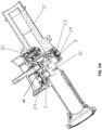
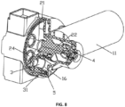
- the airway structure 100 comprises a pipeline 1, a control valve group 2, an air connection sleeve 3, a first elastic body 4 and a second elastic body 5.
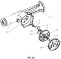
- the pipeline 1 comprises a relatively fixed air connection portion 11 and a sealing plate 40 (see FIG. 1A ).
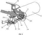
- the pipeline 1 further comprises a surrounding wall 13 and a bottom wall 14 (see FIG. 3 ) provided on the lower periphery of the surrounding wall 13.
- the air connection portion 11 and the surrounding wall 13 are fixedly connected.
- the air connection portion 11 has a connecting base 15 (see FIG. 3 ) protruding into the surrounding wall 13.
- the air connection portion 11 is provided with an air connection passage 42.
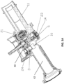
- the upper end surface of the connecting base 15 is concavely provided with the air connecting port 16 (see FIG. 3A ) of the air connection passage 42.
- the sealing plate 40 may be assembled and disassembled in the surrounding wall 13 and is located on the connecting base 15.
- the control valve group 2 comprises a control plate 21 and an air baffle 22 fixedly mounted under the control plate 21.
- the air baffle 22 is inserted into the surrounding wall 13.
- the control plate 21 is located under the sealing plate and above the connecting base 15 (see FIG. 3A ).
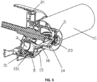
- the first elastic body 4 is located in the surrounding wall 13 and is attached between the bottom wall 14 and the control valve group 2 and abuts against the control valve group 2 to make the control plate 21 abut under the sealing plate.
- the air baffle 22 is protruded with a convex column 23 and the first elastic body 4 is a spring and is sleeved on the convex column 23, and abuts between the air baffle 22 and the bottom wall 14.
- the air connection sleeve 3 slides up and down on the air connection port 16.
- the second elastic body 5 is mounted between the air connection portion 11 and the air connection sleeve 3 and abuts against the air connection sleeve 3 so that the air connection sleeve 3 abuts under the control plate 21.
- the air connection sleeve 3 is always tightly fitted with the control plate 21, so as to realize compensation through the first and second elastic bodies 4 and 5.
- a fixing column 31 is fixed on the outside of the air connection sleeve 3 through a spacer.
- a groove 151 is recessed on the upper end surface of the connection base 15.
- the air connection sleeve 3 is adapted to be inserted into the air connection port 16.
- the fixing column 31 is inserted into the groove 151.
- the second elastic body 5 is a spring.
- the spring 5 is inserted into the groove 151 and abuts between the groove bottom of the groove 151 and the end surface of the fixing column 31.
- the structure is simple, the assembly is convenient, and the compensation is stable and reliable;
- the upper edge of the air connection sleeve 3 extends outward to form an outer flange 32.
- the outer flange 32 is located outside the air connection port to define the deepest insertion position of the air connection sleeve.
- the control valve group 2 may be rotatably connected in the surrounding wall of the pipeline 1 and can rotate relative to the pipeline between at least two switching positions, the switching position are one-to-one corresponding to ventilation, exhaust, or, a first ventilation, a second ventilation, exhaust.
- the control plate 21 is provided with a ventilation port 24 (see FIG. 1 ).
- the control valve group is rotated to control whether the ventilation port and the air connection sleeve are connected or not.
- the control valve group 2 is switched to the closed state to close the airway connection.
- the air connection sleeve and the air connection port are in the connected state, there are two positions.
- the control valve group 2 switches to the exhaust state for the air connection passage to exhaust.
- the air connection sleeve 3 and the ventilation port 24 are staggered, but the air connection sleeve and the ventilation port are connected through the concave C-shaped groove 151 on the upper end surface of the connecting base 15, and the control valve group 2 is switched to the air intake state for the air connection passage to intake air (see FIGS. 6 and 7 ).
- the control plate and the sealing plate can be separated by pressing the control valve group, so as to reduce the friction force between the control plate and the sealing plate, thereby reducing the switching force, and improving the switching convenience.
- the bottom surface of the control plate 31 is provided with an abutting area, and the abutting area is set between every two switching positions.
- the air connection sleeve can be driven to press down through the abutting area.
- the pressure change of the air connection sleeve can improve the user's switching feel, so that the user can perceive whether the switch is in place by switching the feeling.
- it can be kept in the switching position to realize the gear position function.
- a massage pool is provided with above mentioned airway structure of a massage pool with compensation function.
Landscapes
- Health & Medical Sciences (AREA)
- Public Health (AREA)
- Engineering & Computer Science (AREA)
- General Health & Medical Sciences (AREA)
- Epidemiology (AREA)
- Rehabilitation Therapy (AREA)
- Life Sciences & Earth Sciences (AREA)
- Animal Behavior & Ethology (AREA)
- Pain & Pain Management (AREA)
- Veterinary Medicine (AREA)
- Physical Education & Sports Medicine (AREA)
- General Engineering & Computer Science (AREA)
- Architecture (AREA)
- Mechanical Engineering (AREA)
- Civil Engineering (AREA)
- Structural Engineering (AREA)
- Massaging Devices (AREA)
- Valve Housings (AREA)
Claims (8)
- Lüftungsstruktur für ein Massagebecken mit Kompensationsfunktion, die Folgendes aufweist:eine Rohrleitung (1),eine Steuerventilgruppe (2),eine Luftanschlussmuffe (3),einen ersten elastischen Körper (4) undeinen zweiten elastischen Körper (5), wobei die Rohrleitung (1) einen festen Luftanschlussteil (11) und eine Verschlussplatte (40) aufweist; die Steuerventilgruppe (2) eine Steuerplatte (21) und eine Luftleitwand (22), die fest unter der Steuerplatte (21) montiert ist, aufweist, die Steuerplatte (21) sich unter der Verschlussplatte (40) befindet, der erste elastische Körper (4) zwischen der Rohrleitung (1) und der Steuerventilgruppe (2) angebracht ist und an der Luftleitwand (22) der Steuerventilgruppe (2) anliegt, damit die Steuerplatte (21) an der Verschlussplatte (40) anliegt, der feste Luftanschlussteil (11) mit einer Luftanschlussöffnung (16) versehen ist, die Luftanschlussmuffe (3) relativ zur Luftanschlussöffnung (16) verschiebbar ist, der zweite elastische Körper (5) zwischen der Luftanschlussöffnung (16) und der Luftanschlussmuffe (3) montiert ist und an der Luftanschlussmuffe (3) anliegt, damit die Luftanschlussmuffe (3) an der Steuerplatte (21) anliegt.
- Lüftungsstruktur nach Anspruch 1, wobei die Steuerventilgruppe (2) drehend in der Rohrleitung (1) angeschlossen ist und die Steuerplatte (21) mit einer Lüftungsöffnung (24) versehen ist, die Steuerventilgruppe (2) sich dreht und die Lüftungsöffnung (21) steuert, so dass sie mit der Luftanschlussmuffe (3) verbunden wird.
- Lüftungsstruktur nach Anspruch 1, wobei die Rohrleitung (1) eine Umgebungswand (13) und eine Bodenwand (14), die am unteren Umfang der Umgebungswand (13) abgedichtet und befestigt ist, aufweist und die Verschlussplatte (40) in der Umgebungswand (13) befestigt ist, der feste Luftanschlussteil (11) fest mit der Umgebungswand (13) verbunden ist und der feste Luftanschlussteil (11) eine Verbindungsbasis (15) hat, die in die Umgebungswand (13) ragt, der Luftanschlussteil (11) mit einem Luftanschlusskanal (42) versehen ist, die obere Endfläche der Verbindungsbasis (15) mit einem Luftanschlussteil des Luftanschlusskanals gewölbt ist, die Steuerplatte (21) sich an der Verbindungsbasis (15) und in der Umgebungswand (13) befindet.
- Lüftungsstruktur nach Anspruch 3, wobei eine Befestigungssäule (31) durch einen Abstandhalter an der Außenseite der Luftanschlussmuffe (3) befestigt ist, eine Nut (151) an der oberen Endfläche der Verbindungsbasis (15) konkav ausgebildet ist und die Lüftungsanschlussmuffe (3) dafür ausgelegt ist, in die Luftanschlussöffnung (16) eingefügt zu werden, die Befestigungssäule (31) in die Nut (151) eingefügt ist und der zweite elastische Körper (5) in die Nut (151) eingefügt ist und zwischen einem Nutenboden der Nut (151) und der Befestigungssäule (31) anliegt.
- Lüftungsstruktur nach Anspruch 4, wobei der obere Rand der Luftanschlussmuffe (3) sich nach außen erstreckt, um einen Außenflansch (32) zu bilden, und der Außenflansch (32) sich außerhalb der Luftanschlussöffnung (16) befindet.
- Lüftungsstruktur eines Massagebeckens mit Kompensationsfunktion nach Anspruch 1, wobei eine konvexe Säule (23) aus dem Boden der Luftleitwand (22) ragt und der erste elastische Körper (4) auf die konvexe Säule (23) aufgeschoben ist.
- Lüftungsstruktur nach Anspruch 1, wobei die Steuerplatte (21) drehbar mit der Rohrleitung (1) verbunden ist und die Steuerplatte (21) zwischen mindestens zwei Schaltstellungen relativ zur Rohrleitung (1) gedreht wird und die Unterseite der Steuerplatte (21) mit einem Widerlagebereich versehen ist, der Widerlagebereich zwischen jeweils zwei benachbarte Schaltstellungen gesetzt ist und die Luftanschlussmuffe (3) angetrieben wird, um durch den Widerlagebereich nach unten zu drücken.
- Massagebecken, dadurch gekennzeichnet, dass es mit der Lüftungsstruktur eines Massagebeckens mit Kompensationsfunktion nach Anspruch 1 versehen ist.
Priority Applications (1)
| Application Number | Priority Date | Filing Date | Title |
|---|---|---|---|
| EP25178546.5A EP4617533A3 (de) | 2021-07-15 | 2022-07-15 | Atemwegsstruktur eines massagepools mit kompensationsfunktion und massagepool |
Applications Claiming Priority (2)
| Application Number | Priority Date | Filing Date | Title |
|---|---|---|---|
| CN202121613882.0U CN216042922U (zh) | 2021-07-15 | 2021-07-15 | Spa水池带补偿功能的气路结构及spa水池 |
| PCT/IB2022/056556 WO2023286034A1 (en) | 2021-07-15 | 2022-07-15 | Airway structure of a massage pool with compensation function and massage pool |
Related Child Applications (2)
| Application Number | Title | Priority Date | Filing Date |
|---|---|---|---|
| EP25178546.5A Division EP4617533A3 (de) | 2021-07-15 | 2022-07-15 | Atemwegsstruktur eines massagepools mit kompensationsfunktion und massagepool |
| EP25178546.5A Division-Into EP4617533A3 (de) | 2021-07-15 | 2022-07-15 | Atemwegsstruktur eines massagepools mit kompensationsfunktion und massagepool |
Publications (3)
| Publication Number | Publication Date |
|---|---|
| EP4370086A1 EP4370086A1 (de) | 2024-05-22 |
| EP4370086B1 true EP4370086B1 (de) | 2025-07-02 |
| EP4370086C0 EP4370086C0 (de) | 2025-07-02 |
Family
ID=80617620
Family Applications (2)
| Application Number | Title | Priority Date | Filing Date |
|---|---|---|---|
| EP22748462.3A Active EP4370086B1 (de) | 2021-07-15 | 2022-07-15 | Lüftungsstruktur eines massagebeckens mit kompensationsfunktion und massagebecken |
| EP25178546.5A Pending EP4617533A3 (de) | 2021-07-15 | 2022-07-15 | Atemwegsstruktur eines massagepools mit kompensationsfunktion und massagepool |
Family Applications After (1)
| Application Number | Title | Priority Date | Filing Date |
|---|---|---|---|
| EP25178546.5A Pending EP4617533A3 (de) | 2021-07-15 | 2022-07-15 | Atemwegsstruktur eines massagepools mit kompensationsfunktion und massagepool |
Country Status (6)
| Country | Link |
|---|---|
| US (1) | US12128001B2 (de) |
| EP (2) | EP4370086B1 (de) |
| CN (1) | CN216042922U (de) |
| ES (1) | ES3037341T3 (de) |
| PL (1) | PL4370086T3 (de) |
| WO (1) | WO2023286034A1 (de) |
Family Cites Families (33)
| Publication number | Priority date | Publication date | Assignee | Title |
|---|---|---|---|---|
| US3810464A (en) * | 1972-07-17 | 1974-05-14 | Raymond Lee Organization Inc | Whirlpool bath unit |
| DE3311103C2 (de) | 1983-03-26 | 1985-12-12 | Metronic Electronic GmbH, 7210 Rottweil | Luftsprudelmassagegerät |
| IT8422592U1 (it) * | 1984-07-17 | 1986-01-17 | Jacuzzi Europe S P A | Bocchetta per idromassaggio. |
| US4981543A (en) | 1986-07-30 | 1991-01-01 | Softub, Inc. | Tub apparatus |
| US4773104A (en) | 1987-09-24 | 1988-09-27 | Cheng Chung Wang | Inflatable bath-pool with means producing massaging fluid jet |
| US5283915A (en) | 1992-08-10 | 1994-02-08 | Softub, Inc. | Power package for spa apparatus |
| US6199224B1 (en) | 1996-05-29 | 2001-03-13 | Vico Products Mfg., Co. | Cleaning system for hydromassage baths |
| US5809942A (en) | 1996-11-13 | 1998-09-22 | Kralovec; William M. | Pool and spa water heater |
| US6108829A (en) | 1997-03-10 | 2000-08-29 | Wadsworth; A Earl | Portable hot tub |
| US6003166A (en) | 1997-12-23 | 1999-12-21 | Icon Health And Fitness, Inc. | Portable spa |
| JP3172916B2 (ja) * | 1998-06-23 | 2001-06-04 | 富士インジェクタ株式会社 | 冷暖房装置における作動媒体の流路切換装置 |
| US7503082B2 (en) | 1999-04-16 | 2009-03-17 | C. G. Air Systèmes Inc. | Air massage system for bathtub |
| US6357059B1 (en) | 2000-03-28 | 2002-03-19 | Pleasure Time Products (Hk) Limited | Portable spa |
| US6412123B1 (en) | 2000-11-01 | 2002-07-02 | Pleasure Time Products (Hong Kong) Limited | Portable spa |
| US6973681B2 (en) | 2002-02-15 | 2005-12-13 | Pentair Pool Products | Spa jet mounting assembly and method of installation |
| CN2676897Y (zh) | 2003-09-17 | 2005-02-09 | 王正宗 | 按摩水池 |
| CN100382776C (zh) | 2003-09-17 | 2008-04-23 | 王正宗 | 按摩水池 |
| US7236692B2 (en) | 2004-12-01 | 2007-06-26 | Balboa Instruments, Inc. | Spa heater system and methods for controlling |
| CN2794505Y (zh) | 2004-12-02 | 2006-07-12 | 康芙特岚有限责任公司 | 水疗按摩机 |
| JP4041132B2 (ja) * | 2005-04-28 | 2008-01-30 | シーシーアイ株式会社 | エアシリンダ駆動装置 |
| US7797770B2 (en) | 2005-05-23 | 2010-09-21 | Ideal Time Consultants. Limited | Portable spa |
| US20060260038A1 (en) | 2005-05-23 | 2006-11-23 | Lau Vincent W | Portable spa |
| CN202732280U (zh) | 2012-08-09 | 2013-02-13 | 昆山联华印务有限公司 | 水池气泵系统防水结构 |
| US20220325546A1 (en) | 2013-07-18 | 2022-10-13 | Intex Marketing Ltd. | Inflatable spa |
| EP3225764B1 (de) | 2013-07-18 | 2020-09-09 | Intex Marketing Ltd. | Aufblasbares heilbad |
| DE102017102841A1 (de) | 2017-02-13 | 2018-08-16 | Otto Egelhof Gmbh & Co. Kg | Mehrwegventil zur Steuerung eines Kältemittelkreislaufs |
| CN109424221A (zh) | 2017-08-29 | 2019-03-05 | 东辉休闲运动用品(上海)有限公司 | 一种按摩水池空气供应系统及其控制方法 |
| CN112443180A (zh) | 2019-09-03 | 2021-03-05 | 东辉休闲运动用品(上海)有限公司 | 一种控制箱以及按摩水池 |
| CN111895140A (zh) | 2020-08-04 | 2020-11-06 | 厦门吉科卫浴有限公司 | 一种水路切换装置及淋浴设备 |
| US20220071730A1 (en) | 2020-09-09 | 2022-03-10 | Tychon Technologies, Inc. | Position-sensitive magnetically-sensitive tags for surgical procedures |
| WO2022056545A2 (en) | 2020-09-11 | 2022-03-17 | Regents Of The University Of Minnesota | Shape memory alloy microfilament yarns |
| CA3192451A1 (en) | 2020-09-14 | 2022-03-17 | Johannes Bette | Cardiovascular support pump having an impeller with a variable flow area |
| CN112502498B (zh) | 2020-09-29 | 2025-10-17 | 明达实业(厦门)有限公司 | 按摩水池及其气路单元、气路系统和池体 |
-
2021
- 2021-07-15 CN CN202121613882.0U patent/CN216042922U/zh active Active
-
2022
- 2022-07-15 EP EP22748462.3A patent/EP4370086B1/de active Active
- 2022-07-15 ES ES22748462T patent/ES3037341T3/es active Active
- 2022-07-15 US US18/579,211 patent/US12128001B2/en active Active
- 2022-07-15 WO PCT/IB2022/056556 patent/WO2023286034A1/en not_active Ceased
- 2022-07-15 PL PL22748462.3T patent/PL4370086T3/pl unknown
- 2022-07-15 EP EP25178546.5A patent/EP4617533A3/de active Pending
Also Published As
| Publication number | Publication date |
|---|---|
| US12128001B2 (en) | 2024-10-29 |
| CN216042922U (zh) | 2022-03-15 |
| US20240261184A1 (en) | 2024-08-08 |
| WO2023286034A1 (en) | 2023-01-19 |
| EP4617533A2 (de) | 2025-09-17 |
| EP4617533A3 (de) | 2025-12-17 |
| EP4370086A1 (de) | 2024-05-22 |
| PL4370086T3 (pl) | 2025-09-08 |
| ES3037341T3 (en) | 2025-10-01 |
| EP4370086C0 (de) | 2025-07-02 |
Similar Documents
| Publication | Publication Date | Title |
|---|---|---|
| US6698452B2 (en) | Cycle reversing valve for use in heat pumps | |
| US5462085A (en) | Four-way change-over valve for air-conditioner and service valve therewith | |
| US4793375A (en) | Faucet valve cartridge | |
| JP2018100682A (ja) | 流路切換弁 | |
| CN114382919B (zh) | 流路切换阀 | |
| CN107542948B (zh) | 电动阀 | |
| JP2701243B2 (ja) | ボール弁要素を有する混合弁 | |
| EP4370086B1 (de) | Lüftungsstruktur eines massagebeckens mit kompensationsfunktion und massagebecken | |
| CN113357811B (zh) | 进风结构、新风装置及空调 | |
| EP4370085B1 (de) | Ein luftwegsystem eines massagebeckens, bestehend aus einer luftpumpe und einer luftwegeinheit | |
| CN108397583B (zh) | 安全阀及使用该安全阀的壁挂炉供暖系统 | |
| CN217056493U (zh) | 减压阀装置和燃气设备 | |
| EP3828467B1 (de) | Regelventil für ein gaskochgerät und gaskochgerät mit besagtem regelventil | |
| JP2000320711A (ja) | 電動式コントロールバルブ | |
| EP4370083B1 (de) | Eine luftkanalstruktur eines massagebeckens mit einem steuerventil | |
| CN118030880A (zh) | 按键阀及其使用方法 | |
| CN217108322U (zh) | 一种电动切换阀 | |
| CN213685341U (zh) | 一种燃气灶具阀总成及具有其的燃气灶具 | |
| CN222102825U (zh) | 一种快开阀芯及龙头 | |
| CN218894991U (zh) | 一种流量调节阀及制氧机 | |
| CN223677053U (zh) | 净水器用流量调节阀 | |
| CN220556061U (zh) | 阀组件 | |
| CN115978244B (zh) | 一种手控和电控自动切换的烤炉阀 | |
| CN114060569B (zh) | 一种阀和龙头 | |
| CN223595073U (zh) | 一种碟片阀 |
Legal Events
| Date | Code | Title | Description |
|---|---|---|---|
| STAA | Information on the status of an ep patent application or granted ep patent |
Free format text: STATUS: UNKNOWN |
|
| STAA | Information on the status of an ep patent application or granted ep patent |
Free format text: STATUS: THE INTERNATIONAL PUBLICATION HAS BEEN MADE |
|
| PUAI | Public reference made under article 153(3) epc to a published international application that has entered the european phase |
Free format text: ORIGINAL CODE: 0009012 |
|
| STAA | Information on the status of an ep patent application or granted ep patent |
Free format text: STATUS: REQUEST FOR EXAMINATION WAS MADE |
|
| 17P | Request for examination filed |
Effective date: 20240215 |
|
| AK | Designated contracting states |
Kind code of ref document: A1 Designated state(s): AL AT BE BG CH CY CZ DE DK EE ES FI FR GB GR HR HU IE IS IT LI LT LU LV MC MK MT NL NO PL PT RO RS SE SI SK SM TR |
|
| DAV | Request for validation of the european patent (deleted) | ||
| DAX | Request for extension of the european patent (deleted) | ||
| GRAP | Despatch of communication of intention to grant a patent |
Free format text: ORIGINAL CODE: EPIDOSNIGR1 |
|
| STAA | Information on the status of an ep patent application or granted ep patent |
Free format text: STATUS: GRANT OF PATENT IS INTENDED |
|
| INTG | Intention to grant announced |
Effective date: 20250124 |
|
| GRAS | Grant fee paid |
Free format text: ORIGINAL CODE: EPIDOSNIGR3 |
|
| GRAA | (expected) grant |
Free format text: ORIGINAL CODE: 0009210 |
|
| STAA | Information on the status of an ep patent application or granted ep patent |
Free format text: STATUS: THE PATENT HAS BEEN GRANTED |
|
| AK | Designated contracting states |
Kind code of ref document: B1 Designated state(s): AL AT BE BG CH CY CZ DE DK EE ES FI FR GB GR HR HU IE IS IT LI LT LU LV MC MK MT NL NO PL PT RO RS SE SI SK SM TR |
|
| REG | Reference to a national code |
Ref country code: GB Ref legal event code: FG4D |
|
| REG | Reference to a national code |
Ref country code: CH Ref legal event code: EP |
|
| REG | Reference to a national code |
Ref country code: DE Ref legal event code: R096 Ref document number: 602022016986 Country of ref document: DE |
|
| REG | Reference to a national code |
Ref country code: IE Ref legal event code: FG4D |
|
| U01 | Request for unitary effect filed |
Effective date: 20250804 |
|
| U07 | Unitary effect registered |
Designated state(s): AT BE BG DE DK EE FI FR IT LT LU LV MT NL PT RO SE SI Effective date: 20250812 |
|
| REG | Reference to a national code |
Ref country code: ES Ref legal event code: FG2A Ref document number: 3037341 Country of ref document: ES Kind code of ref document: T3 Effective date: 20251001 |
|
| PGFP | Annual fee paid to national office [announced via postgrant information from national office to epo] |
Ref country code: ES Payment date: 20250804 Year of fee payment: 4 |
|
| PGFP | Annual fee paid to national office [announced via postgrant information from national office to epo] |
Ref country code: PL Payment date: 20250714 Year of fee payment: 4 |
|
| PGFP | Annual fee paid to national office [announced via postgrant information from national office to epo] |
Ref country code: CZ Payment date: 20250715 Year of fee payment: 4 |
|
| U20 | Renewal fee for the european patent with unitary effect paid |
Year of fee payment: 4 Effective date: 20250915 |
|
| PG25 | Lapsed in a contracting state [announced via postgrant information from national office to epo] |
Ref country code: IS Free format text: LAPSE BECAUSE OF FAILURE TO SUBMIT A TRANSLATION OF THE DESCRIPTION OR TO PAY THE FEE WITHIN THE PRESCRIBED TIME-LIMIT Effective date: 20251102 |
|
| PG25 | Lapsed in a contracting state [announced via postgrant information from national office to epo] |
Ref country code: NO Free format text: LAPSE BECAUSE OF FAILURE TO SUBMIT A TRANSLATION OF THE DESCRIPTION OR TO PAY THE FEE WITHIN THE PRESCRIBED TIME-LIMIT Effective date: 20251002 |
|
| PG25 | Lapsed in a contracting state [announced via postgrant information from national office to epo] |
Ref country code: HR Free format text: LAPSE BECAUSE OF FAILURE TO SUBMIT A TRANSLATION OF THE DESCRIPTION OR TO PAY THE FEE WITHIN THE PRESCRIBED TIME-LIMIT Effective date: 20250702 |
|
| PG25 | Lapsed in a contracting state [announced via postgrant information from national office to epo] |
Ref country code: GR Free format text: LAPSE BECAUSE OF FAILURE TO SUBMIT A TRANSLATION OF THE DESCRIPTION OR TO PAY THE FEE WITHIN THE PRESCRIBED TIME-LIMIT Effective date: 20251003 |
|
| PG25 | Lapsed in a contracting state [announced via postgrant information from national office to epo] |
Ref country code: RS Free format text: LAPSE BECAUSE OF FAILURE TO SUBMIT A TRANSLATION OF THE DESCRIPTION OR TO PAY THE FEE WITHIN THE PRESCRIBED TIME-LIMIT Effective date: 20251002 |
|
| REG | Reference to a national code |
Ref country code: CH Ref legal event code: H13 Free format text: ST27 STATUS EVENT CODE: U-0-0-H10-H13 (AS PROVIDED BY THE NATIONAL OFFICE) Effective date: 20260224 |
|
| PG25 | Lapsed in a contracting state [announced via postgrant information from national office to epo] |
Ref country code: SM Free format text: LAPSE BECAUSE OF FAILURE TO SUBMIT A TRANSLATION OF THE DESCRIPTION OR TO PAY THE FEE WITHIN THE PRESCRIBED TIME-LIMIT Effective date: 20250702 |
|
| PG25 | Lapsed in a contracting state [announced via postgrant information from national office to epo] |
Ref country code: CH Free format text: LAPSE BECAUSE OF NON-PAYMENT OF DUE FEES Effective date: 20250731 |
|
| PG25 | Lapsed in a contracting state [announced via postgrant information from national office to epo] |
Ref country code: SK Free format text: LAPSE BECAUSE OF FAILURE TO SUBMIT A TRANSLATION OF THE DESCRIPTION OR TO PAY THE FEE WITHIN THE PRESCRIBED TIME-LIMIT Effective date: 20250702 |