EP4369482A2 - Energiespeichervorrichtung und elektrische vorrichtung - Google Patents
Energiespeichervorrichtung und elektrische vorrichtung Download PDFInfo
- Publication number
- EP4369482A2 EP4369482A2 EP23208188.5A EP23208188A EP4369482A2 EP 4369482 A2 EP4369482 A2 EP 4369482A2 EP 23208188 A EP23208188 A EP 23208188A EP 4369482 A2 EP4369482 A2 EP 4369482A2
- Authority
- EP
- European Patent Office
- Prior art keywords
- arc segment
- connecting plate
- segment
- notch
- plastic member
- Prior art date
- Legal status (The legal status is an assumption and is not a legal conclusion. Google has not performed a legal analysis and makes no representation as to the accuracy of the status listed.)
- Granted
Links
Images
Classifications
-
- H—ELECTRICITY
- H01—ELECTRIC ELEMENTS
- H01M—PROCESSES OR MEANS, e.g. BATTERIES, FOR THE DIRECT CONVERSION OF CHEMICAL ENERGY INTO ELECTRICAL ENERGY
- H01M50/00—Constructional details or processes of manufacture of the non-active parts of electrochemical cells other than fuel cells, e.g. hybrid cells
- H01M50/60—Arrangements or processes for filling or topping-up with liquids; Arrangements or processes for draining liquids from casings
- H01M50/609—Arrangements or processes for filling with liquid, e.g. electrolytes
- H01M50/627—Filling ports
-
- H—ELECTRICITY
- H01—ELECTRIC ELEMENTS
- H01M—PROCESSES OR MEANS, e.g. BATTERIES, FOR THE DIRECT CONVERSION OF CHEMICAL ENERGY INTO ELECTRICAL ENERGY
- H01M50/00—Constructional details or processes of manufacture of the non-active parts of electrochemical cells other than fuel cells, e.g. hybrid cells
- H01M50/50—Current conducting connections for cells or batteries
- H01M50/531—Electrode connections inside a battery casing
- H01M50/533—Electrode connections inside a battery casing characterised by the shape of the leads or tabs
-
- H—ELECTRICITY
- H01—ELECTRIC ELEMENTS
- H01M—PROCESSES OR MEANS, e.g. BATTERIES, FOR THE DIRECT CONVERSION OF CHEMICAL ENERGY INTO ELECTRICAL ENERGY
- H01M50/00—Constructional details or processes of manufacture of the non-active parts of electrochemical cells other than fuel cells, e.g. hybrid cells
- H01M50/60—Arrangements or processes for filling or topping-up with liquids; Arrangements or processes for draining liquids from casings
- H01M50/609—Arrangements or processes for filling with liquid, e.g. electrolytes
-
- H—ELECTRICITY
- H01—ELECTRIC ELEMENTS
- H01M—PROCESSES OR MEANS, e.g. BATTERIES, FOR THE DIRECT CONVERSION OF CHEMICAL ENERGY INTO ELECTRICAL ENERGY
- H01M10/00—Secondary cells; Manufacture thereof
- H01M10/05—Accumulators with non-aqueous electrolyte
- H01M10/052—Li-accumulators
- H01M10/0525—Rocking-chair batteries, i.e. batteries with lithium insertion or intercalation in both electrodes; Lithium-ion batteries
-
- H—ELECTRICITY
- H01—ELECTRIC ELEMENTS
- H01M—PROCESSES OR MEANS, e.g. BATTERIES, FOR THE DIRECT CONVERSION OF CHEMICAL ENERGY INTO ELECTRICAL ENERGY
- H01M50/00—Constructional details or processes of manufacture of the non-active parts of electrochemical cells other than fuel cells, e.g. hybrid cells
- H01M50/10—Primary casings; Jackets or wrappings
- H01M50/102—Primary casings; Jackets or wrappings characterised by their shape or physical structure
- H01M50/103—Primary casings; Jackets or wrappings characterised by their shape or physical structure prismatic or rectangular
-
- H—ELECTRICITY
- H01—ELECTRIC ELEMENTS
- H01M—PROCESSES OR MEANS, e.g. BATTERIES, FOR THE DIRECT CONVERSION OF CHEMICAL ENERGY INTO ELECTRICAL ENERGY
- H01M50/00—Constructional details or processes of manufacture of the non-active parts of electrochemical cells other than fuel cells, e.g. hybrid cells
- H01M50/10—Primary casings; Jackets or wrappings
- H01M50/147—Lids or covers
-
- H—ELECTRICITY
- H01—ELECTRIC ELEMENTS
- H01M—PROCESSES OR MEANS, e.g. BATTERIES, FOR THE DIRECT CONVERSION OF CHEMICAL ENERGY INTO ELECTRICAL ENERGY
- H01M50/00—Constructional details or processes of manufacture of the non-active parts of electrochemical cells other than fuel cells, e.g. hybrid cells
- H01M50/10—Primary casings; Jackets or wrappings
- H01M50/183—Sealing members
- H01M50/186—Sealing members characterised by the disposition of the sealing members
-
- H—ELECTRICITY
- H01—ELECTRIC ELEMENTS
- H01M—PROCESSES OR MEANS, e.g. BATTERIES, FOR THE DIRECT CONVERSION OF CHEMICAL ENERGY INTO ELECTRICAL ENERGY
- H01M50/00—Constructional details or processes of manufacture of the non-active parts of electrochemical cells other than fuel cells, e.g. hybrid cells
- H01M50/50—Current conducting connections for cells or batteries
- H01M50/531—Electrode connections inside a battery casing
-
- H—ELECTRICITY
- H01—ELECTRIC ELEMENTS
- H01M—PROCESSES OR MEANS, e.g. BATTERIES, FOR THE DIRECT CONVERSION OF CHEMICAL ENERGY INTO ELECTRICAL ENERGY
- H01M50/00—Constructional details or processes of manufacture of the non-active parts of electrochemical cells other than fuel cells, e.g. hybrid cells
- H01M50/50—Current conducting connections for cells or batteries
- H01M50/572—Means for preventing undesired use or discharge
- H01M50/584—Means for preventing undesired use or discharge for preventing incorrect connections inside or outside the batteries
- H01M50/59—Means for preventing undesired use or discharge for preventing incorrect connections inside or outside the batteries characterised by the protection means
- H01M50/593—Spacers; Insulating plates
-
- H—ELECTRICITY
- H01—ELECTRIC ELEMENTS
- H01M—PROCESSES OR MEANS, e.g. BATTERIES, FOR THE DIRECT CONVERSION OF CHEMICAL ENERGY INTO ELECTRICAL ENERGY
- H01M2220/00—Batteries for particular applications
- H01M2220/20—Batteries in motive systems, e.g. vehicle, ship, plane
-
- Y—GENERAL TAGGING OF NEW TECHNOLOGICAL DEVELOPMENTS; GENERAL TAGGING OF CROSS-SECTIONAL TECHNOLOGIES SPANNING OVER SEVERAL SECTIONS OF THE IPC; TECHNICAL SUBJECTS COVERED BY FORMER USPC CROSS-REFERENCE ART COLLECTIONS [XRACs] AND DIGESTS
- Y02—TECHNOLOGIES OR APPLICATIONS FOR MITIGATION OR ADAPTATION AGAINST CLIMATE CHANGE
- Y02E—REDUCTION OF GREENHOUSE GAS [GHG] EMISSIONS, RELATED TO ENERGY GENERATION, TRANSMISSION OR DISTRIBUTION
- Y02E60/00—Enabling technologies; Technologies with a potential or indirect contribution to GHG emissions mitigation
- Y02E60/10—Energy storage using batteries
Definitions
- the present disclosure relates to the technical field of energy storage, and in particular to an energy storage device and an electrical apparatus.
- Rechargeable batteries such as lithium-ion batteries
- the common energy storage devices have advantages such as high energy density, high power density, repeated use and long storage time.
- the rechargeable batteries have been widely used in electric vehicles such as electric vehicles and electric bicycles as well as large-sized and medium-sized electric apparatuses such as energy storage facilities.
- a main object of the present disclosure is to provide an energy storage device, which has good fluidity when electrolyte is filled, and improves humidity uniformity of an electrode assembly.
- the present disclosure employs a following technical solution.
- an energy storage device comprises: a housing having an opening and accommodating electrolyte; an electrode assembly accommodated in the housing; a top cover covering the opening and provided with a liquid injection hole; a lower plastic member having a through hole, wherein the lower plastic member is arranged on a side, close to the electrode assembly, of the top cover and comprises a plurality of bosses arranged at intervals in a length direction of the lower plastic member, the plurality of bosses at least comprise a first boss and a second boss, the first boss and the second boss are respectively located on two ends of the lower plastic member in the length direction thereof, the plurality of bosses are located on a side, towards the electrode assembly, of the lower plastic member, and the through hole is in communication with the liquid injection hole; a connecting plate arranged on the side, towards the electrode assembly, of the lower plastic member, wherein a gap is formed between at least a part of the connecting plate and the lower plastic member in a thickness direction of the connecting plate
- an electrical appliance comprises the above-mentioned energy storage device.
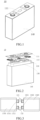
- the energy storage device 10 comprises a housing 140, an electrode assembly 130, a top cover 111, a lower plastic member 112 (which may be made of plastic, for example), a connecting plate 120 and an insulating adhesive sheet 150.
- the housing 140 has an opening for accommodating electrolyte.
- the electrode assembly 130 is accommodated in the housing 140.
- the top cover 111 covers the opening of the housing 140, and has a liquid injection hole 1170.
- the lower plastic member 112 has a through hole 1180.
- the lower plastic member 112 is arranged on a side of the top cover 111 close to the electrode assembly 130.
- the lower plastic member 112 is provided with a plurality of bosses 1120 at intervals along a length direction X of the lower plastic member 112.
- the bosses 1120 at least comprise a first boss 1121 and a second boss 1122, which are respectively located at both ends of the lower plastic member 112 in the length direction X.
- the bosses 1120 are located at a side of the lower plastic member 112 towards the electrode assembly 130.
- the through hole 1180 is in communication with the liquid injection hole 1170.
- the connecting plate 120 is arranged on the side of the lower plastic member 112 towards the electrode assembly 130; and in a thickness direction of the connecting plate 120, a gap is formed between at least a part of the lower connecting plate 120 and the lower plastic member 112.
- the insulating adhesive sheet 150 is attached to a side of the connecting plate 120 towards the electrode assembly 130, and covers the connecting plate 120 and the through hole 1180.
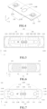
- a notch 113 is provided on a side of each of the first boss 1121 and the second boss 1122 close to the connecting plate 120.
- the notch 113 comprises a first arc segment 1141, a second arc segment 1142, a third arc segment 1143 and a fourth arc segment 1144, which are sequentially arranged along a width direction of the lower plastic member 112.
- the first arc segment 1141 is connected with the second arc segment 1142, the third arc segment 1143 is connected with the fourth arc segment 1144, the second arc segment 1142 is connected with the third arc segment 1143, the first arc segment 1141 is closer to the through hole 1180 than the second arc segment 1142, and the fourth arc segment 1144 is closer to the through hole 1180 than the third arc segment 1143.
- the first arc segment 1141, the second arc segment 1142, the third arc segment 1143 and the fourth arc segment 1144 form an edge of the notch 113.
- the insulating adhesive sheet 150, the connecting plate 120 and the edge enclose to form a first flow channel for electrolyte, and the electrolyte flows into the liquid injection hole 1170 and can flow to the electrode assembly 130 through the first flow channel.
- a gap is formed between the connecting plate 120 and the lower plastic member 112 in the energy storage device, a notch 113 is provided on a side of the boss 1120 close to the connecting plate 120, and the insulating adhesive sheet 150 covers the connecting plate 120 and the through hole 1180, so that the insulating adhesive sheet 150, the connecting plate 120 and the edge enclose to form a first flow channel for electrolyte.
- the insulating adhesive sheet 150 covers the connecting plate 120 and the through hole 1180, so that the electrolyte flows along the gap between the insulating adhesive sheet 150 and the connecting plate 120 and the lower plastic member 112, and then flow out through the notch 113 of the boss 1120, and then flows to the electrode assembly 130, thereby realizing the diversion of the electrolyte, and enabling the electrolyte to adequately flow to various parts of the electrode assembly 130, improving humidity uniformity of the electrode assembly 130.
- the edge of the notch 113 is formed by the first arc segment 1141, the second arc segment 1142, the third arc segment 1143 and the fourth arc segment 1144, so that a corner of the notch 113 of the boss 1120 is rounded.
- a flow rate of the electrolyte at the corner of the notch 113 is faster, so that the electrolyte can flow into the electrode assembly 130 more quickly and smoothly.
- the corner of the notch 113 is provided as a rounded corner, which can prevent the corner of the notch 113 from scratching the tab, and improve the reliability of the energy storage device and the electrical appliance.
- the electrode assembly 130 comprises a main body, a first tab and a second tab, one of the first tab and the second tab is a positive tab, and the other thereof is a negative tab.
- the main body is a winding main body
- the electrode assembly 130 comprises a first main body 1310 and a second main body 1320, which are stacked in the thickness direction Z and placed in the housing 140.
- the first main body 1310 is connected with a first main body first tab 1311 (hereinafter referred to as "first tab 1311”) and a first main body second tab 1312 (hereinafter referred to as "second tab 1312").
- the second main body 1320 is connected with a second main body first tab 1321 (hereinafter referred to as “first tab 1321”) and a second main body second tab 1322 (hereinafter referred to as “second tab 1322").
- first tab 1321 a second main body first tab 1321
- second tab 1322 a second main body second tab 1322
- the electrode assembly 130 may also be a single main body, or formed by combining three, four or more main bodies, which is not limited in the present disclosure.
- two bosses 1120 i.e., a first boss 1121 and a second boss 1122, are formed on both ends of the lower plastic member 112 in the length direction X.
- the first boss 1121 is provided with a first notch 1131
- the second boss 1122 is provided with a second notch 1132
- the first notch 1131 and the second notch 1132 are opened opposite to each other.
- the first boss 1121 and the second boss 1122 extend into the opening and abut against a side wall of the opening of the housing 140, to form guidance and limitation for the top cover 111 to be installed on the opening of the housing 140, so that the top cover 111 may be quickly positioned and installed on the housing 140, thereby improving the installation efficiency of the top cover 111 and the housing 140; and the boss 1120 abuts against a main body in the housing 140 to fix the main body.
- the top cover 111 is provided with two poles 115, i.e., a first pole 1151 and a second pole 1152.
- the energy storage device 10 comprises two connecting plates 120, i.e., a first connecting plate 121 and a second connecting plate 122.
- the first connecting plate 121 is located at a side close to the first boss 1121
- the second connecting plate 122 is located at a side close to the second boss 1122.
- a side of the first boss 1121 close to the first connecting plate 121 is provided with a first notch 1131, and the first notch 1131 comprises a first arc segment 1141, a second arc segment 1142, a third arc segment 1143, a fourth arc segment 1144, which are sequentially arranged along the width direction Y of the lower plastic member 112.
- the first arc segment 1141 is connected with the second arc segment 1142, the third arc segment 1143 is connected with the fourth arc segment 1144, the second arc segment 1142 is connected with the third arc segment 1143; the first arc segment 1141 is closer to the through hole 1180 than the second arc segment 1142, and the fourth arc segment 1144 is closer to the through hole 1180 than the third arc segment 1143.
- the first arc segment 1141, the second arc segment 1142, the third arc segment 1143, the fourth arc segment 1144 form the edge of the first notch 1131.
- the first insulating adhesive sheet 151, the first connecting plate 121 and the first edge enclose to form a first flow channel for electrolyte.
- a gap is formed between the first connecting plate 121 and the lower plastic member 112, a side of the first boss 1121 close to the first connecting plate 121 is provided with a first notch 1131, and the first insulating adhesive sheet 151 covers the first connecting plate 121 and the through hole 1180, so that the first insulating adhesive sheet 151, the first connecting plate 121 and the first edge enclose to form a first flow channel for electrolyte.
- the first insulating adhesive sheet 151 covers the first connecting plate 121 and the through hole 1180, so that the electrolyte flows along the gap between the first insulating adhesive sheet 151 and the first connecting plate 121 and the lower plastic member 112, and then flow out through the first notch 1131 of the first boss 1121, and then flows to the electrode assembly 130, thereby realizing the diversion of the electrolyte, and enabling the electrolyte to adequately flow to various parts of the electrode assembly 130.
- a reinforcing rib 1190 extending towards a side of the electrode assembly 130 is provided on either side of the lower plastic member 112 in the width direction Y.
- a gap is formed between the first connecting plate 121 and the reinforcing rib 1190 in the width direction of the lower plastic member 112, and a gap is formed between at least a part of the first insulating adhesive sheet 151 located on the first transition portion 1211 and the reinforcing rib 1190 in the width direction Y of the lower plastic member 112.
- the first insulating adhesive sheet 151, the first connecting plate 121 and the reinforcing rib 1190 enclose to form a second flow channel for electrolyte, and the electrolyte is injected through the liquid injection hole 1170 and flows to the electrode assembly 130 through the second flow channel.
- the first insulating adhesive sheet 151 covers the first connecting plate 121 and the through hole 1180, so that the electrolyte flows along the gap between the first insulating adhesive sheet 151 and the first connecting plate 121 and the lower plastic member 112, and then flows out through the gap between the first connecting plate 121 and the reinforcing rib 1190, and then flows to the electrode assembly 130, thereby realizing the diversion of the electrolyte, and the second flow channel is matched with the first flow channel, enabling the electrolyte to adequately flow to various parts of the electrode assembly 130.
- the first connecting plate 121 comprises a first pole connecting portion 1214, a first transition portion 1211 and two first tab connecting portions 1212.
- the first pole connecting portion 1214 is connected with the two first tab connecting portions 1212 through the first transition portion 1211.
- the two first tab connecting portions 1212 are located at a side of the first transition portion 1211 away from the first notch 1131, and the two first tab connecting portions 1212 are spaced apart in the width direction of the first connecting plate 121.
- the through hole 1180 is located between the two first tab connecting portions 1212.
- the first insulating adhesive sheet 151 completely covers an area between the two first tab connecting portions 1212.
- the electrolyte flowing through the through hole 1180 flows towards the gap between the first connecting plate 121 and the lower plastic member 112 under the flow-guiding action of the first insulating adhesive sheet 151, and then flows into the electrode assembly 130 through the first flow channel and the second flow channel.
- the first connecting plate 121 further comprises a first protrusion 1213.
- the first protrusion 1213 is located on a side of the first transition portion 1211 towards the first notch 1131, and at least a part of the first protrusion 1213 is located in the first notch 1131.
- the first protrusion 1213 when the first connecting plate 121 is laser welded to the first pole 1151 through the first pole connecting portion 1214, the first protrusion 1213 in conducive to abut a welding nozzle (for example, a copper nozzle) for laser welding against a side edge of the first connecting plate 121 on which the first protrusion 1213 is provided, and the first notch 1131 provides an avoidance space for the welding nozzle to abut against the first protrusion 1213.
- a welding nozzle for example, a copper nozzle
- the first protrusion 1213 can provide an additional current flow path when the current is too large, to improve the current carrying capacity of the first connecting plate 121, and improve the stability and safety of the energy storage device.
- a gap is formed between the first transition portion 1211 and the first boss 1121, and the first insulating adhesive sheet 151 covers the gap.
- the gap is formed between the first transition portion 1211 and the first boss 1121 and the first insulating adhesive sheet 151 covering the gap, so that the electrolyte of the first flow channel flows into the electrode assembly 130 through the first notch 1131.
- the first insulating adhesive sheet 151 covers the gap, at least a part of the first insulating adhesive sheet 151 covers the edge of the first boss 1121, which can prevent the edge of the first boss 1121 from scratching the tab.
- the first insulating adhesive sheet 151 covers the first protrusion 1213 and at least a part of the first notch 1131.
- the first insulating adhesive sheet 151 covers the first boss, and the first insulating adhesive sheet 151 completely covers the first connecting plate 121, thereby forming the insulation function of the first connecting plate 121, and avoiding the short circuit caused by the contact between the first connecting plate 121 and a pole piece in the main body.
- the first insulating adhesive sheet 151 covers at least a part of the first notch 1131, so that the electrolyte needs to flow out of the first notch 1131 through the first arc segment 1141 and the fourth arc segment 1144, and the flow rate of the electrolyte is relatively increased through the first arc segment 1141 and the fourth arc segment 1144.
- the first insulating adhesive sheet 151 covers on a side of the first boss 1121 towards the electrode assembly 130.
- the adhesive force of the first insulating adhesive sheet 151 can be improved and the first insulating adhesive sheet 151 can be prevented from falling off.
- the first insulating adhesive sheet 151 also covers at least a part of the first main body 1310 and the first tab 1311 connected to the first tab connecting portion 1212, and the first tab 1321 and at least a part of the second main body 1320.
- the first insulating adhesive sheet 151 also covering at least a part of the first main body 1310 connected to the first tab connecting portion 1212 and the first tab 1311, and the first tab 1321 and at least a part of the second main body 1320, the first insulating adhesive sheet 151 completely covers the first connecting patch 121, the first tab 1311, and the first tab 1321, in order to avoid the short circuit caused by welding slag falling into the main body, and improve the stability of the first tab connecting portion 1212 and the first tab 1311 and the first tab 1321 after they are welded.
- the first insulating adhesive sheet 151 is formed by connecting a plurality of insulating adhesive sub-sheets, and the insulating adhesive sub-sheets cover different areas of the first connecting plate 121, the first main body 1310, the first tab 1311, the second main body 1320 and the first tab 1321, respectively, and an overlapped area is formed between adjacent insulating adhesive sub-sheets . This can reduce the process difficulty of the first insulating adhesive sheet 151, improve the adhering strength of the first insulating adhesive sheet 151 in different areas, and reduce the manufacturing difficulty and cost of the first insulating adhesive sheet 151.
- the first notch 1131 further comprises at least one of the followings: a first straight segment 1145, a second straight segment 1146 and a third straight segment 1147.
- the first straight segment 1145 is connected between the first arc segment 1141 and the second arc segment 1142
- the second straight segment 1146 is connected between the third arc segment 1143 and the fourth arc segment 1144
- the third straight segment 1147 is connected to the second arc segment 1142 and the third arc segment 1143.
- first straight segment 1145 being connected between the first arc segment 1141 and the second arc segment 1142
- second straight segment 1146 being connected between the third arc segment 1143 and the fourth arc segment 1144
- third straight segment 1147 being connected between the second arc segment 1142 and the third arc segment 1143
- An angle between the first straight segment 1145 and the third straight segment 1147 is an obtuse angle.
- an opening of the first notch 1131 is relatively enlarged, which further facilitates the electrolyte to flow into the gap between the first protrusion 1213 and the first notch 1131, increases a radian of an corner of the first straight segment 1145 and the third straight segment 1147, and further increases the flow rate of the electrolyte at the first straight segment 1145 and the third straight segment 1147, so that the electrolyte can flow into the electrode assembly 130 faster.
- the angle between the first straight segment 1145 and the third straight segment 1147 may also be a right angle.
- the angle between the second straight segment 1146 and the third straight segment 1147 is an obtuse angle.
- the opening of the first notch 1131 is relatively enlarged, which further facilitates the electrolyte to flow into the gap between the first protrusion 1213 and the first notch 1131, increases a radian of a corner of the second straight segment 1146 and the third straight segment 1147, and further increases the flow rate of the electrolyte at the second straight segment 1146 and the third straight segment 1147, so that the electrolyte can flow into the electrode assembly 130 faster.
- the angle between the second straight segment 1146 and the third straight segment 1147 may also be a right angle.
- a radian of the first arc segment 1141 is ⁇ /3 to ⁇ /2, for example, ⁇ /3, 5 ⁇ /12, ⁇ /2, etc.
- the radian of the first arc segment 1141 may also be less than ⁇ /3 or more than ⁇ /2, which is not limited in the present disclosure.
- a radian of the fourth arc segment 1144 is ⁇ /3 to ⁇ /2, for example, ⁇ /3, 5 ⁇ /12, ⁇ /2, etc.
- the radian of the first arc segment 1141 may also be less than ⁇ /3 or more than ⁇ /2, which is not limited in the present disclosure.
- the radian of the first arc segment 1141 may be the same as or different from the radian of the fourth arc segment 1144.
- An arc radius of the first arc segment 1141 is 1mm to 3mm, such as 1.0mm, 1.5mm, 2.0mm, 2.5mm, 3.0mm, etc., which will not be listed exhaustively herein.
- the arc radius of the first arc segment 1141 may be less than 1mm or more than 3mm.
- the arc radius of the fourth arc segment 1144 is 1mm to 3mm, such as 1.0mm, 1.5mm, 2.0mm, 2.5mm, 3.0mm, etc., which will not be listed exhaustively herein.
- the arc radius of the fourth arc segment 1144 may be less than 1mm or more than 3mm.
- the arc radius of the first arc segment 1141 may be same as or different from the arc radius of the fourth arc segment 1144.
- a radian of the second arc segment 1142 is ⁇ /3 to ⁇ /2, for example, ⁇ /3, 5 ⁇ /12, ⁇ /2, etc.
- the radian of the second arc segment 1142 may also be less than ⁇ /3 or more than ⁇ /2, which is not limited in the present disclosure.
- a radian of the third arc segment 1143 is ⁇ /3 to ⁇ /2, for example, ⁇ /3, 5 ⁇ /12, ⁇ /2, etc.
- the radian of the third arc segment 1143 may also be less than ⁇ /3 or more than ⁇ /2, which is not limited in the present disclosure.
- the radian of the second arc segment 1142 may be the same as or different from that of the first arc segment 1141, the third arc segment 1143 and the fourth arc segment 1144.
- the arc radius of the second arc segment 1142 is 1mm to 3mm, such as 1.0mm, 1.5mm, 2.0mm, 2.5mm, 3.0mm, etc., which will not be listed exhaustively herein.
- the arc radius of the second arc segment 1142 may be less than 1mm or more than 3mm.
- An arc radius of the third arc segment 1143 is 1mm to 3mm, such as 1.0mm, 1.5mm, 2.0mm, 2.5mm, 3.0mm, etc., which will not be listed exhaustively herein.
- the arc radius of the third arc segment 1143 may be less than 1mm or more than 3mm.
- the arc radius of the second arc segment 1142 may be the same as or different from that of the first arc segment 1141, the third arc segment 1143 and the fourth arc segment 1144.
- a width of the first notch 1131 is 40% to 60% of a width of the first boss 1121, such as 40%, 45%, 50%, 55%, 60%, etc., which will not be listed exhaustively herein. It is ensured that there is enough gap between the first notch 1131 and the first protrusion 1213, to facilitate flowing the electrolyte, facilitate the welding nozzle to abut on the first connecting plate 121, and form enough avoidance space.
- the width of the first notch 1131 may be less than 40% of the width of the first boss 1121 or more than 60% of the width of the first boss 1121, which is not limited in the present disclosure.
- a length of the lower plastic member 112 may be 250mm to 280mm, such as 250mm, 260.88mm, 270mm, 280mm, etc.
- a width of the lower plastic member 112 may be 50mm to 60mm, such as 50mm, 52mm, 53mm, 58.08mm, 60mm, etc.
- a maximum width of the first boss 1121 is same as the width of the lower plastic member 112, and a thickness of the first boss 1121 may be 2mm to 3mm, such as 2.0mm, 2.2mm, 2.58mm, 2.8mm, 3.0mm, etc.
- a length of the first boss 1121 may be 15mm to 25mm, such as 15mm, 18mm, 20mm, 22mm and 25mm, which is a maximum length of the first boss 1121.
- a width of the first notch 1131 is 25mm to 30mm, for example, 25mm, 26mm, 27mm, 28.13mm, 29mm and 30mm, which will not be listed exhaustively in the present disclosure.
- the above width is the maximum width of the first notch 1131. It is ensured that there is enough gap between the first notch 1131 and the first protrusion 1213, to facilitate flowing the electrolyte, facilitate the welding nozzle to abut on the first connecting plate 121, and form enough avoidance space.
- the width of the first notch 1131 may be less than 25mm or more than 30mm, which is not limited in the present disclosure.
- a depth of the first notch 1131 is 20% to 30% of the length of the first boss 1121, such as 20%, 22%, 25%, 28%, 30%, etc., which will not be listed exhaustively herein. It is ensured that there is enough gap between the first notch 1131 and the first protrusion 1213, to facilitate flowing the electrolyte, facilitate the welding nozzle to abut on the first connecting plate 121, and form enough avoidance space.
- the depth of the first notch 1131 may be less than 20% of the length of the first boss 1121 or more than 30% of the length of the first boss 1121, which is not limited in the present disclosure.
- the depth of the first notch 1131 is 3mm to 6mm, such as 3.0mm, 3.5mm, 4.0mm, 4.5mm, 5.0mm, 5.5mm and 6.0mm, which will not be listed exhaustively herein. It is ensured that there is enough gap between the first notch 1131 and the first protrusion 1213, to facilitate flowing the electrolyte, facilitate the welding nozzle to abut on the first connecting plate 121, and form enough avoidance space.
- the depth of the first notch 1131 may also be less than 3mm or more than 6mm, which is not limited in the present disclosure.
- the first boss 1121 is symmetrical about a central axis of the lower plastic member 112 in the length direction X.
- the first boss 1121 has a symmetrical structure
- the first notch 1131 has a symmetrical structure
- the first arc segment 1141 and the fourth arc segment 1144 are symmetrical
- the second arc segment 1142 and the third arc segment 1143 are symmetrical, so that the electrolyte uniformly flows into the gap between the first protrusion 1213 and the first notch 1133 from both sides of the lower plastic member 112 in the width direction Y thereof, thereby further enabling the electrolyte to uniformly flow into the main body.
- the first protrusion 1213 comprises a top surface towards the first notch 1131, and a first side surface and a second side surface on both sides of the top surface in the width direction of the first connecting plate 121.
- the top surface, the first side surface and the second side surface each is a plane, the top surface is perpendicular to the length direction X of the lower plastic member 112, and an angle between the first side surface or the second side surface and the top surface is a right angle or an obtuse angle.
- an orthogonal projection of the first protrusion 1213 on the lower plastic member 112 is rectangular; and when the angle between the side surface and the top surface of the first protrusion 1213 is an obtuse angle, the orthographic projection of the first protrusion 1213 on the lower plastic member 112 is trapezoidal.
- the angle between the side surface and the top surface of the first protrusion 1213 may also be an acute angle, and the first side surface and the second side surface of the first protrusion 1213 may also be an arc surface or a concave-convex surface, which is not limited in the present disclosure.
- the top surface of the first protrusion 1213 is arranged opposite to the third straight line section 1147 and a first preset gap is formed therebetween, and the first preset gap is 2mm to 5mm, such as 2mm, 3mm, 4mm, 5mm, etc., which will not be listed exhaustively herein.
- the first side surface of the first protrusion 1213 is arranged opposite to the first straight segment 1145 and a second preset gap is formed therebetween, and the second preset gap is 3mm to 10mm, such as 3mm, 5mm, 8mm, 10mm, etc., which will not be listed exhaustively herein.
- the second side surface of the first protrusion 1213 is arranged opposite to the second straight segment 1146 and a third preset gap is formed therebetween, and the third preset gap is 3mm to 10mm, such as 3mm, 5mm, 8mm, 10mm, etc., which will not be listed exhaustively herein.
- the width of the first protrusion 1213 is 20%-50% of the width of the first transition portion 1211, such as 20%, 25%, 30%, 35%, 40%, 45%, 50%, etc., which will not be listed exhaustively herein.
- the specific width of the first protrusion 1213 may be determined according to the specific size of the first connecting plate 121.
- the first protrusion 1213 may have enough width to facilitate the abutting of the welding nozzle, so that the first protrusion 1213 can provide an additional current flow path; meanwhile, it can be avoided that the first notch 1131 is too wide to cause too small area of the first boss 1121.
- the width of the first protrusion 1213 may be less than 20% of the width of the first transition portion 1211, or the width of the first protrusion 1213 may be more than 50% of the width of the first transition portion 1211, which is not limited in the present disclosure.
- the length of the first protrusion 1213 is 10%-30% of the length of the first transition portion 1211, such as 10%, 15%, 20%, 25%, 30%, etc., which will not be listed exhaustively herein.
- the specific length of the first protrusion 1213 can be determined according to the specific size of the first connecting plate 121.
- the first protrusion 1213 can have enough length, so that the abutting of the welding nozzle cannot be affected by a welding position of the first pole connecting portion 1214, and the first protrusion 1213 can provide an additional current flow path. Meanwhile, the first notch 1131 can be prevented from being too deep in the length direction X of the top cover 111.
- the first protrusion 1213 is symmetrical about a central axis of the first connecting plate 121 in the length direction X, that is, in the width direction Y of the first connecting plate 121, the first protrusion 1213 is located at a middle position of the first connecting plate 121.
- the first pole connecting portion 1214 is located in a middle area of the first transition portion 1211, and the first protrusion 1213 is located in the middle position of the first connecting plate 121, so that the welding nozzle can be abut against the first connecting plate 121.
- a shape of the first protrusion 1213 is matched with a shape of the first notch 1131.
- the orthographic projections of the first protrusion 1213 and the first notch 1131 on the lower plastic member 112 are rectangular, or the orthographic projections of the first protrusion 1213 and the first notch 1131 on the lower plastic member 112 are trapezoidal.
- the shape of the first protrusion 1213 may not be matched with the shape of the first notch 1131, for example, the first protrusion 1213 is rectangular and the first notch 1131 is semicircular, which is not limited in the present disclosure.
- a second notch 1132 is formed on a side of the second boss 1122 close to the second connecting plate 122, and the second notch 1132 comprises a first arc segment 1141, a second arc segment 1142, a third arc segment 1143, a fourth arc segment 1144, which are sequentially arranged along the width direction Y of the lower plastic member 112.
- the first arc segment 1141 is connected with the second arc segment 1142
- the third arc segment 1143 is connected with the fourth arc segment 1144
- the second arc segment 1142 is connected with the third arc segment 1143.
- the first arc segment 1141 is closer to the through hole 1180 than the second arc segment 1142, and the fourth arc segment 1144 is closer to the liquid injection hole 1170 than the third arc segment 1143.
- the first arc segment 1141, the second arc segment 1142, and the third arc segment 1143 and the fourth arc segment 1144 form a second edge of the second notch 1132.
- the second insulating adhesive sheet 152, the second connecting plate 122 and the second edge enclose to form a first flow channel for electrolyte.
- a gap is formed between the second connecting plate 122 and the lower plastic member 112, the second notch 1132 is formed on a side of the second boss 1122 close to the second connecting plate 122, and the second insulating adhesive sheet 152 covers the second connecting plate 122, so that the second insulating adhesive sheet 152, the second connecting plate 122 and the second edge enclose to form a first flow channel for electrolyte.
- a part of the electrolyte may flow along the gap between the second insulating adhesive sheet 152 and the second connecting plate 122 and the lower plastic member 112, and then flow out through the second notch 1132 of the second boss 1122, and then flow to the electrode assembly 130, thereby realizing the diversion of the electrolyte, and enabling the electrolyte to adequately flow to various parts of the electrode assembly 130.
- the lower plastic member 112 has reinforcing ribs 1190 extending towards a side of the electrode assembly 130 on both sides thereof in the width direction Y.
- a gap is formed between the second connecting plate 122 and the reinforcing rib 1190 in the width direction Y of the lower plastic member 112, and a gap is formed between at least a part of the second insulating adhesive sheet 152 located on the second transition portion 1221 and the reinforcing rib 1190 in the width direction Y of the lower plastic member 112.
- the second insulating adhesive sheet 152, the second connecting plate 122 and the reinforcing rib 1190 enclose to form a second flow channel for electrolyte, and the electrolyte is injected through the liquid injection hole 1170 and flows to the electrode assembly 130 through the second flow channel.
- the second insulating adhesive sheet 152 By the second insulating adhesive sheet 152, the second connecting plate 122 and the reinforcing rib 1190 enclosing to form the second channel of electrolyte, when the electrolyte is injected into the housing 140 through the liquid injection hole 1170, the second insulating adhesive sheet 152 covers the second connecting plate 122, so that a part of the electrolyte flows along the gap between the second insulating adhesive sheet 152 and the second connecting plate 122 and the lower plastic member 112, and then the electrolyte may flow out through the gap between the second connecting plate 122 and the reinforcing rib 1190, and then flow to the electrode assembly 130, thereby realizing the diversion of the electrolyte, and the second flow channel is matched with the first flow channel, so that the electrolyte can adequately flow to various parts of the electrode assembly 130.
- the second connecting plate 122 comprises a second pole connecting portion 1224, a second transition portion 1221 and two second tab connecting portions 1222; and the second pole connecting portion 1224 is connected with the two second tab connecting portions 1222 through the second transition portion 1221.
- the second tab connecting portion 1222 is located on a side of the second transition portion 1221 away from the second notch 1132, and two second tab connecting portions 1222 are spaced apart in the width direction Y of the second connecting plate 122.
- the second insulating adhesive sheet 152 completely covers an area between the two second tab connecting portions 1222.
- the second connecting plate 122 further comprises a second protrusion 1223.
- the second protrusion 1223 is located on a side of the second transition portion 1221 towards the second notch 1132, and at least a part of the second protrusion 1223 is located in the second notch 1132.
- the second protrusion 1223 when the second connecting plate 122 is laser welded to the second pole 1152 through the second pole connecting portion 1224, the second protrusion 1223 is conducive to abut a welding nozzle for laser welding against a side edge of the second connecting plate 122 on which the second protrusion 1223 is provided, and the second notch 132 provides an avoidance space for the welding nozzle to abut against the second protrusion 1223. This can improve the stability of laser welding between the second connecting plate 122 and the second pole 1152, and improve the efficiency and yield of laser welding between the second connecting plate 122 and the second pole 1152.
- the second protrusion 1223 can provide an additional current flow path when the current is too large, to improve the current carrying capacity of the second connecting plate 122, and improve the stability and safety of the energy storage device.
- a gap is formed between the second transition portion 1221 and the second boss 1122, and the second insulating adhesive sheet 152 covers the gap.
- the gap is formed between the second transition portion 1221 and the second boss 1122, and the second insulating adhesive sheet 152 covers the gap, so that the electrolyte of the first flow channel flows into the electrode assembly 130 through the second notch 1132.
- the second insulating adhesive sheet 152 covers the gap, at least a part of the second insulating adhesive sheet 152 covers the edge of the second boss 1122, which can prevent the edge of the second boss 1122 from scratching the second tab.
- the second insulating adhesive sheet 152 covers the second protrusion 1223 and at least a part of the second notch 1132.
- the second insulating adhesive sheet 152 covers the second connecting plate 122, to form the insulating function of the second connecting plate 122, thereby preventing the second connecting plate 122 from contacting with the pole piece in the main body to cause the short circuit.
- the electrolyte needs to flow out of the second notch 1132 through the first arc segment 1141 and the fourth arc segment 1144, and the flow rate of the electrolyte is relatively increased through the first arc segment 1141 and the fourth arc segment 1144.
- the second insulating adhesive sheet 152 covers a side of the second boss 1122 towards the electrode assembly 130.
- the adhesive force of the second insulating adhesive sheet 152 can be improved and the second insulating adhesive sheet 152 can be prevented from falling off.
- the second insulating adhesive sheet 152 also covers at least a part of the first main body 1310 and the second tab 1312 connected to the second tab connecting portion 1222, and the second tab 1322 and at least a part of the second main body 1320.
- the second insulating adhesive sheet 152 completely covers the second connecting plate 122 and the first main body second tab 1312 and the second main body second tab 1322, to avoid welding slags from falling into the main body to cause the short circuit, and improve the stability between the first tab connecting portion 1212 and the first main body second tab 1312 and the second main body second tab 1322 after they are welded.
- the second insulating adhesive sheet 152 is formed by connecting a plurality of insulating adhesive sub-sheets, and the insulating adhesive sub-sheets cover different areas of the second connecting plate 122, the first main body 1310, the first main body second tab 1312, the second main body 1320 and the second main body second tab 1322, respectively, and an overlapped area is formed between the insulating adhesive sub-sheets adjacent to one another. This can reduce the process difficulty of adhering the second insulating adhesive sheet 152, improve the adhering efficiency of the second insulating adhesive sheet 152 in different areas, and reduce the manufacturing difficulty and cost of the second insulating adhesive sheet 152.
- the second notch 1132 further comprises at least one of a first straight segment 1145, a second straight segment 1146 and a third straight segment 1147, wherein the first straight segment 1145 is connected between the first arc segment 1141 and the second arc segment 1142, the second straight segment 1146 is connected between the third arc segment 1143 and the fourth arc segment 1144, and the third straight segment 1147 is connected to the second arc segment 1142 and the third arc segment 1143.
- An angle between the first straight segment 1145 and the third straight segment 1147 is an obtuse angle.
- an opening of the second notch 1132 is relatively enlarged, thereby further facilitating the electrolyte to flow into the gap between the second protrusion 1223 and the second notch 1132, increasing a radian of a corner of the first straight segment 1145 and the third straight segment 1147, and further increasing the flow rate of the electrolyte at the first straight segment 1145 and the third straight segment 1147, so that the electrolyte can flow into the electrode assembly 130 faster.
- the angle between the first straight segment 1145 and the third straight segment 1147 may be a right angle.
- An angle between the second straight segment 1146 and the third straight segment 1147 is an obtuse angle.
- the opening of the second notch 1132 is relatively enlarged, further facilitating the electrolyte to flow into the gap between the second protrusion 1223 and the second notch 1132, increasing a radian of a corner of the second straight segment 1146 and the third straight segment 1147, and further increasing the flow rate of electrolyte at the second straight segment 1146 and the third straight segment 1147, so that the electrolyte can flow into the electrode assembly 130 faster.
- the angle between the second straight segment 1146 and the third straight segment 1147 may also be a right angle.
- the radian of the first arc segment 1141 is ⁇ /3 to ⁇ /2, for example, ⁇ /3, 5 ⁇ /12, ⁇ /2, etc.
- the radian of the first arc segment 1141 is ⁇ /3 to ⁇ /2, for example, ⁇ /3, 5 ⁇ /12, ⁇ /2, etc.
- the radian of the first arc segment 1141 may also be less than ⁇ /3 or more than ⁇ /2, which is not limited in the present disclosure.
- the radian of the fourth arc segment 1144 is ⁇ /3 to ⁇ /2, for example, ⁇ /3, 5 ⁇ /12, ⁇ /2, etc.
- the radian of the fourth arc segment 1144 may also be less than ⁇ /3 or more than ⁇ /2, which is not limited in the present disclosure.
- the radian of the first arc segment 1141 may be the same as or different from the radian of the fourth arc segment 1144.
- the arc radius of the first arc segment 1141 is 1mm to 3mm, such as 1.0mm, 1.5mm, 2.0mm, 2.5mm, 3.0mm, etc., which will not be listed exhaustively herein.
- the arc radius of the first arc segment 1141 may be less than 1mm or more than 3mm.
- the arc radius of the fourth arc segment 1144 is 1mm to 3mm, such as 1.0mm, 1.5mm, 2.0mm, 2.5mm, 3.0mm, etc., which will not be listed exhaustively herein.
- the arc radius of the fourth arc segment 1144 may be less than 1mm or more than 3mm.
- the arc radius of the first arc segment 1141 may be same as or different from the arc radius of the fourth arc segment 1144.
- the radian of the second arc segment 1142 is ⁇ /3 to ⁇ /2, for example, ⁇ /3, 5 ⁇ /12, ⁇ /2, etc.
- the radian of the second arc segment 1142 is beneficial to provide the flow of electrolyte at the second arc segment 1142 and facilitate the formation of the second notch 1132.
- the radian of the second arc segment 1142 may also be less than ⁇ /3 or more than ⁇ /2, which is not limited in the present disclosure.
- the radian of the third arc segment 1143 is ⁇ /3 to ⁇ /2, for example, ⁇ /3, 5 ⁇ /12, ⁇ /2, etc.
- the radian of the third arc segment 1143 may also be less than ⁇ /3 or more than ⁇ /2, which is not limited in the present disclosure.
- the radian of the second arc segment 1142 may be the same as or different from that of the first arc segment 1141, the third arc segment 1143 and the fourth arc segment 1144.
- the arc radius of the second arc segment 1142 is 1mm to 3mm, such as 1.0mm, 1.5mm, 2.0mm, 2.5mm, 3.0mm, etc., which will not be listed exhaustively herein.
- the arc radius of the second arc segment 1142 may be less than 1mm or more than 3mm.
- the arc radius of the third arc segment 1143 is 1mm to 3mm, such as 1.0mm, 1.5mm, 2.0mm, 2.5mm, 3.0mm, etc., which will not be listed exhaustively herein.
- the arc radius of the third arc segment 1143 may be less than 1mm or more than 3mm.
- the arc radius of the second arc segment 1142 may be the same as or different from that of the first arc segment 1141, the third arc segment 1143 and the fourth arc segment 1144.
- a width of the second notch 1132 is 40% to 60% of a width of the second boss 1122, such as 40%, 45%, 50%, 55%, 60%, etc., which will not be listed exhaustively herein. It is ensured that there is enough gap between the second notch 1132 and the second protrusion 1223, which facilitates flowing the electrolyte, facilitates the welding nozzle to abut on the second connecting plate 122, and forms enough avoidance space.
- the width of the second notch 1132 may be less than 40% of the width of the second boss 1122 or more than 60% of the width of the second boss 1122, which is not limited in the present disclosure.
- the length of the lower plastic member 112 may be 250mm to 280mm, such as 250mm, 260.88mm, 270mm, 280mm, etc.
- a width of the lower plastic member 112 may be 50mm to 60mm, such as 50mm, 52mm, 53mm, 58.08mm, 60mm, etc.
- a maximum width of the second boss 1122 is same as the width of the lower plastic member 112, and a thickness of the second boss 1122 may be 2mm to 3mm, such as 2.0mm, 2.2mm, 2.58mm, 2.8mm, 3.0mm, etc.
- a length of the second boss 1122 may be 15mm to 25mm, such as 15mm, 18mm, 20mm, 22mm and 25mm, which is a maximum length of the second boss 1122.
- a width of the second notch 1132 is 25mm to 30mm, such as 25mm, 26mm, 27mm, 28.13mm, 29mm and 30mm, which will not be listed exhaustively herein.
- the above width is the maximum width of the second notch 1132. It is ensured that there is enough gap between the second notch 1132 and the second protrusion 1223, which facilitates flowing the electrolyte, facilitates the welding nozzle to abut on the second connecting plate 122, and forms enough avoidance space.
- the width of the second notch 1132 may also be less than 25mm or more than 30mm, which is not limited in the present disclosure.
- a depth of the second notch 1132 is 20% to 30% of the length of the second boss 1122, such as 20%, 22%, 25%, 28%, 30%, etc., which will not be listed exhaustively herein. It is ensured that there is enough gap between the second notch 1132 and the second protrusion 1223, which facilitates flowing the electrolyte, facilitates the welding nozzle to abut on the second connecting plate 122, and forms enough avoidance space.
- the depth of the second notch 1132 may be less than 20% of the length of the second boss 1122 or more than 30% of the length of the second boss 1122, which is not limited in the present disclosure.
- the depth of the second notch 1132 is 3mm to 6mm, such as 3.0mm, 3.5mm, 4.0mm, 4.5mm, 5.0mm, 5.5mm and 6.0mm, which will not be listed exhaustively herein. It is ensured that there is enough gap between the second notch 1132 and the second protrusion 1223, which facilitates flowing the electrolyte, facilitates the welding nozzle to abut on the second connecting plate 122, and forms enough avoidance space.
- the depth of the second notch 1132 may also be less than 3mm or more than 6mm, which is not limited in the present disclosure.
- the second boss 1122 is symmetrical about the central axis of the lower plastic member 112 in the length direction X.
- the second boss 1122 has a symmetrical structure
- the second notch 1132 has a symmetrical structure
- the first arc segment 1141 and the fourth arc segment 1144 are symmetrical
- the second arc segment 1142 and the third arc segment 1143 are symmetrical, so that the electrolyte uniformly flows into the gap between the second boss 1223 and the second notch 1133 from both sides of the lower plastic member 112 in the width direction Y thereof, thereby further enabling the electrolyte to uniformly flow into the main body.
- the second protrusion 1223 comprises a top surface towards the second notch 1132, and a first side surface and a second side surface located on both sides of the top surface in the width direction of the second connecting plate 122.
- the top surface, the first and second side surfaces each is a plane, the top surface is perpendicular to the length direction X of the lower plastic member 112, and an angle between the first side surface or the second side surface and the top surface is a right angle or an obtuse angle.
- an orthographic projection of the second protrusion 1223 on the lower plastic member 112 is rectangular; and when the angle between the side surface and the top surface of the second protrusion 1223 is an obtuse angle, the orthographic projection of the second protrusion 1223 on the lower plastic member 112 is trapezoidal.
- the angle between the side surface and the top surface of the second protrusion 1223 may also be an acute angle, and the first side surface and the second side surface of the second protrusion 1223 may also be an arc surface or a concave-convex surface, which is not limited in the present disclosure.
- the top surface of the second protrusion 1223 is arranged opposite to the third straight line section 1147 and a first preset gap is formed therebetween, and the first preset gap is 2mm to 5mm, such as 2mm, 3mm, 4mm, 5mm, etc., which will not be listed exhaustively herein.
- the first side surface of the second protrusion 1223 is arranged opposite to the first straight segment 1145 and a second preset gap is formed therebetween, and the second preset gap is 3mm to 10mm, such as 3mm, 5mm, 8mm, 10mm, etc., which will not be listed exhaustively herein.
- the second side surface of the second protrusion 1223 is arranged opposite to the second straight segment 1146 and a third preset gap is formed therebetween, and the third preset gap is 3mm to 10mm, such as 3mm, 5mm, 8mm, 10mm, etc., which will not be listed exhaustively herein.
- the width of the second protrusion 1223 is 20%-50% of the width of the second transition portion 1221, such as 20%, 25%, 30%, 35%, 40%, 45%, 50%, etc., which will not be listed exhaustively herein.
- the specific width of the second protrusion 1223 may be determined according to the specific size of the second connecting plate 122.
- the second protrusion 1223 can have enough width to facilitate the abutting of the welding nozzle, so that the second protrusion 1223 can provide an additional current flow path; meanwhile, it can be avoided that the second notch 1132 is too wide to cause too small area of the second boss 1122.
- the width of the second protrusion 1223 may be less than 20% of the width of the second transition portion 1221, or the width of the second protrusion 1223 may be more than 50% of the width of the second transition portion 1221, which is not limited in the present disclosure.
- the length of the second protrusion 1223 is 10%-30% of the length of the second transition portion 1221, such as 10%, 15%, 20%, 25%, 30%, etc., which will not be listed exhaustively herein.
- the specific length of the second protrusion 1223 may be determined according to the specific size of the second connecting plate 122.
- the second protrusion 1223 may have enough length, so that the abutting of the welding nozzle cannot be affected by a welding position of the second pole connecting portion 1224, and the second protrusion 1223 can provide an additional current flow path. Meanwhile, the second notch 1132 can be prevented from being too deep in the length direction X of the top cover 111.
- the second protrusion 1223 is symmetrical about a central axis of the second connecting plate 122 in the length direction X thereof, that is, in the width direction Y of the second connecting plate 122, the second protrusion 1223 is located at a middle position of the second connecting plate 122.
- the second pole connecting portion 1224 is located in a middle area of the second transition portion 1221, and the second protrusion 1223 is located in the middle position of the second connecting plate 122, so that the welding nozzle can be abut against the second connecting plate 122.
- a shape of the second protrusion 1223 is matched with a shape of the second notch 1132.
- the orthographic projection of the second protrusion 1223 and the second notch 1132 on the lower plastic member 112 each is rectangular, or the orthographic projection of the second protrusion 1223 and the second notch 1132 on the lower plastic member 112 each is trapezoidal.
- the shape of the second protrusion 1223 may not be matched with the shape of the second notch 1132, for example, the second protrusion 1223 is rectangular and the second notch 1132 is semicircular, which is not limited in the present disclosure.
- first boss 1121 and the second boss 1122 are symmetrically arranged on the top cover 111, and the shapes and sizes of the first boss 1121 and the second boss 1122 may be completely the same.
- the first connecting plate 121 is a positive connecting plate, the first tab of the main body is a positive tab, and the first pole 1151 is a positive pole; and the second connecting plate 122 is a negative connecting plate, the second tab of the main body is a negative tab, and the second pole 1152 is a negative pole.
- the first connecting plate 121 is a negative connecting plate, the first tab of the main body is a negative tab, and the first pole 1151 is a negative pole; and the second connecting plate 122 is a positive connecting plate, the second tab of main body is a positive tab, and the second pole 1152 is a positive pole.
- the positive connecting plate may be made of an aluminum, and the negative connecting plate may be made of a copper.
- the first connecting plate 121 and the second connecting plate 122 may be symmetrically arranged on the top cover 111, and the shapes and sizes of the first connecting plate 121 and the second connecting plate 122 may be completely symmetrical.
- the structure of the first connecting plate 121 may be different from that of the second connecting plate 122, or only the structure of the second protrusion 1223 on the first connecting plate 121 is completely same as that of the second protrusion 1223 on the second connecting plate 122.
- the first connecting plate 121 and the second connecting plate 122 may be respectively provided with a positioning hole or a positioning groove, and the lower plastic member 112 is provided with a positioning protrusion.
- the first connecting plate 121 and the second connecting plate 122 can be quickly positioned on the lower plastic member 112, and the position deviation of the first connecting plate 121 and the second connecting plate 122 on the lower plastic member 112 can be avoided.
- the insulating adhesive sheet 150 is, for example, an insulating tape.
- the insulating adhesive sheet 150 may also be other functional films having adhesive and insulating functions, which will not be limited in the present disclosure.
- the top cover 111 is further provided with an explosion-proof valve 1160, through which high-temperature and high-pressure gas generated in the housing 140 can be discharged in time.
- the energy storage device provided in the present disclosure may be, for example, a single cell or a battery module comprising a plurality of single cells.
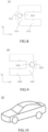
- An embodiment of the present disclosure also provides an electric appliance comprising the above-mentioned energy storage device.
- the electric appliance may be, for example, a vehicle 20 shown in FIG. 10 .
- a gap is formed between the connecting plate and the lower plastic member in the energy storage device, a notch is formed on a side of the boss close to the connecting plate, and the insulating adhesive sheet covers the connecting plate and the through hole, so that the insulating adhesive sheet, the connecting plate and the edge enclose to form a first flow channel for electrolyte.
- the insulating adhesive sheet covers the connecting plate and the through hole, so that the electrolyte flows along the gap between the insulating adhesive sheet and the connecting plate and the lower plastic member, and then the electrolyte may flow out through the notch of the boss, and then flow to the electrode assembly, thereby realizing the diversion of the electrolyte, and enabling the electrolyte to adequately flow to various parts of the electrode assembly.
- the edge of the notch is formed by the first arc segment, the second arc segment, the third arc segment and the fourth arc segment, so that the corner of the notch of the boss is rounded, when the electrolyte flows through the notch, the flow rate of the electrolyte at the corner of the notch is faster, so that the electrolyte can flow into the electrode assembly more quickly and smoothly; meanwhile, the corner of the notch is provided as a rounded corner, which can prevent the corner of the notch from scratching the tab, thereby improving the reliability of the energy storage device, and thus improving the reliability of the electrical appliance.
- connection refers to two or more than two, unless otherwise explicitly defined.
- Terms such as “connection” should be understood broadly.
- “connection” may refer to a fixed connection, a detachable connection, or an integral connection.
- directions or positional relationships indicated by the terms “upper” and “lower” are based on the directions or positional relationships shown in the drawings, only for the convenience of describing the embodiments of the present disclosure and simplifying the description, instead of indicating or implying that the referred devices or units must have a specific direction, be constructed and operated in a specific direction, and therefore, should not be understood as limitations on the embodiments of the present disclosure.
- an embodiment means that a specific feature, structure, material or characteristic described in connection with this embodiment or example is included in at least one embodiment or example of the embodiments of the present disclosure.
- the schematic expressions of the above terms do not necessarily refer to the same embodiment or example.
- the specific features, structures, materials or characteristics described may be combined in any one or more embodiments or examples in a suitable manner.
Landscapes
- Chemical & Material Sciences (AREA)
- Chemical Kinetics & Catalysis (AREA)
- Electrochemistry (AREA)
- General Chemical & Material Sciences (AREA)
- Engineering & Computer Science (AREA)
- Materials Engineering (AREA)
- Manufacturing & Machinery (AREA)
- Secondary Cells (AREA)
- Sealing Battery Cases Or Jackets (AREA)
Applications Claiming Priority (1)
| Application Number | Priority Date | Filing Date | Title |
|---|---|---|---|
| CN202211414921.3A CN115579597B (zh) | 2022-11-11 | 2022-11-11 | 储能装置及用电设备 |
Publications (3)
| Publication Number | Publication Date |
|---|---|
| EP4369482A2 true EP4369482A2 (de) | 2024-05-15 |
| EP4369482A3 EP4369482A3 (de) | 2024-07-10 |
| EP4369482B1 EP4369482B1 (de) | 2025-04-30 |
Family
ID=84588022
Family Applications (1)
| Application Number | Title | Priority Date | Filing Date |
|---|---|---|---|
| EP23208188.5A Active EP4369482B1 (de) | 2022-11-11 | 2023-11-07 | Energiespeichervorrichtung und elektrische vorrichtung |
Country Status (4)
| Country | Link |
|---|---|
| US (1) | US11784381B1 (de) |
| EP (1) | EP4369482B1 (de) |
| CN (1) | CN115579597B (de) |
| HU (1) | HUE071861T2 (de) |
Families Citing this family (9)
| Publication number | Priority date | Publication date | Assignee | Title |
|---|---|---|---|---|
| CN116014389B (zh) * | 2023-02-09 | 2023-06-30 | 深圳海润新能源科技有限公司 | 储能装置及用电设备 |
| CN116014390B (zh) * | 2023-02-09 | 2023-06-13 | 深圳海润新能源科技有限公司 | 储能装置和用电设备 |
| CN115939692B (zh) | 2023-02-09 | 2023-05-23 | 深圳海润新能源科技有限公司 | 下塑胶组件、端盖组件、储能装置及用电设备 |
| CN116231179B (zh) * | 2023-04-12 | 2024-07-23 | 厦门海辰储能科技股份有限公司 | 端盖组件、电池和储能装置 |
| CN116231249A (zh) * | 2023-04-14 | 2023-06-06 | 珠海冠宇电池股份有限公司 | 电池及其壳体组件 |
| WO2025010676A1 (zh) * | 2023-07-12 | 2025-01-16 | 深圳海辰储能控制技术有限公司 | 端盖组件、电池单体、电池组件及储能系统 |
| CN222705780U (zh) * | 2024-02-02 | 2025-04-01 | 宁德时代新能源科技股份有限公司 | 电池单体、电池及用电装置 |
| CN119267330B (zh) * | 2024-10-29 | 2025-12-09 | 润电能源科学技术有限公司 | 消除间隙的方法及轴流式风机 |
| CN119965501B (zh) * | 2025-04-11 | 2025-06-06 | 蜂巢能源科技股份有限公司 | 电芯及电池包 |
Family Cites Families (20)
| Publication number | Priority date | Publication date | Assignee | Title |
|---|---|---|---|---|
| KR101023878B1 (ko) * | 2008-06-16 | 2011-03-22 | 삼성에스디아이 주식회사 | 이차 전지 |
| EP3544090B1 (de) * | 2016-12-02 | 2020-12-16 | Contemporary Amperex Technology Co., Limited | Abdeckplattenanordnung für hochleistungsbatterie und hochleistungsbatterie damit |
| CN206878046U (zh) * | 2016-12-02 | 2018-01-12 | 宁德时代新能源科技股份有限公司 | 二次电池 |
| CN108666519B (zh) * | 2017-03-31 | 2020-07-10 | 比亚迪股份有限公司 | 电池盖板组件、单体电池、电池模组、动力电池包和电动汽车 |
| CN207800664U (zh) * | 2018-02-01 | 2018-08-31 | 宁德时代新能源科技股份有限公司 | 顶盖组件以及动力电池 |
| CN210073933U (zh) * | 2019-08-08 | 2020-02-14 | 合肥力翔电池科技有限责任公司 | 一种无极柱矩形结构顶盖 |
| CN213150888U (zh) * | 2020-09-21 | 2021-05-07 | 江苏塔菲尔新能源科技股份有限公司 | 一种电池顶盖及电池 |
| CN213401338U (zh) * | 2020-10-23 | 2021-06-08 | 东莞塔菲尔新能源科技有限公司 | 一种动力电池顶盖结构及动力电池 |
| CN114497836A (zh) | 2020-10-26 | 2022-05-13 | 昆山聚创新能源科技有限公司 | 全极耳顶盖组件及全极耳电池 |
| CN213660565U (zh) * | 2020-12-10 | 2021-07-09 | 厦门海辰新能源科技有限公司 | 一种动力电池的减振透气下塑胶 |
| JP7280906B2 (ja) * | 2021-03-10 | 2023-05-24 | プライムプラネットエナジー&ソリューションズ株式会社 | 二次電池およびその製造方法 |
| JP7581372B2 (ja) * | 2021-04-02 | 2024-11-12 | 香港時代新能源科技有限公司 | エンドキャップアセンブリ、電池セル、電池及び電池セルの製造方法と機器 |
| CN215418522U (zh) * | 2021-07-29 | 2022-01-04 | 蜂巢能源科技有限公司 | 一种顶盖组件及锂电池 |
| CN216450732U (zh) * | 2021-10-18 | 2022-05-06 | 厦门海辰新能源科技有限公司 | 电池的盖体组件及电池 |
| CN217361843U (zh) | 2022-01-26 | 2022-09-02 | 上海兰钧新能源科技有限公司 | 一种具有限位连接片的电池连接装置 |
| CN217468721U (zh) * | 2022-02-28 | 2022-09-20 | 瑞浦兰钧能源股份有限公司 | 一种电池顶盖及电池 |
| CN216958265U (zh) * | 2022-03-23 | 2022-07-12 | 中创新航科技股份有限公司 | 电池盖板组件、电池及电池组 |
| CN217086732U (zh) * | 2022-04-20 | 2022-07-29 | 中创新航科技股份有限公司 | 电池盖板组件及电池 |
| CN217641706U (zh) | 2022-04-25 | 2022-10-21 | 天津市捷威动力工业有限公司 | 一种下塑胶结构、顶盖组件及动力电池 |
| CN217134507U (zh) | 2022-06-07 | 2022-08-05 | 宁德时代新能源科技股份有限公司 | 电池单体、电池及用电装置 |
-
2022
- 2022-11-11 CN CN202211414921.3A patent/CN115579597B/zh active Active
-
2023
- 2023-02-23 US US18/113,396 patent/US11784381B1/en active Active
- 2023-11-07 EP EP23208188.5A patent/EP4369482B1/de active Active
- 2023-11-07 HU HUE23208188A patent/HUE071861T2/hu unknown
Also Published As
| Publication number | Publication date |
|---|---|
| CN115579597A (zh) | 2023-01-06 |
| US11784381B1 (en) | 2023-10-10 |
| CN115579597B (zh) | 2023-03-24 |
| EP4369482B1 (de) | 2025-04-30 |
| EP4369482A3 (de) | 2024-07-10 |
| HUE071861T2 (hu) | 2025-09-28 |
Similar Documents
| Publication | Publication Date | Title |
|---|---|---|
| EP4369482B1 (de) | Energiespeichervorrichtung und elektrische vorrichtung | |
| KR102327289B1 (ko) | 배터리 | |
| US10826048B2 (en) | Secondary battery | |
| US20230261278A1 (en) | Battery pack and vehicle comprising same | |
| JP2025113486A (ja) | 蓄電装置 | |
| KR100959870B1 (ko) | 보호회로 조립체 및 이를 구비하는 배터리 팩 | |
| CN216720236U (zh) | 转接片、电池单体、电池及用电装置 | |
| KR20110103859A (ko) | 이차 전지 | |
| KR100973314B1 (ko) | 보호회로 조립체 및 이를 구비하는 배터리 팩 | |
| WO2024098421A1 (zh) | 储能装置及用电设备 | |
| KR20090103427A (ko) | 보호회로기판 및 이를 구비하는 배터리 팩 | |
| KR100973309B1 (ko) | 이차 전지용 절연 케이스 및 이를 구비하는 이차 전지 | |
| CN101404339B (zh) | 二次电池 | |
| CN219759640U (zh) | 电池及电池模组 | |
| KR20050020894A (ko) | 전극탭을 캔의 단변부에 위치시킨 이차전지 | |
| CN219106333U (zh) | 连接结构、盖板组件及电池 | |
| CN218005185U (zh) | 一种圆柱电池与电池模组 | |
| WO2024066744A1 (zh) | 电池、电池组及电子设备 | |
| KR100571232B1 (ko) | 리드 플레이트 및 이를 사용한 캔형 이차 전지 | |
| CN223501999U (zh) | 电池单体、用电设备及转接件 | |
| CN120473619B (zh) | 一种下塑胶、端盖组件、储能装置及用电设备 | |
| CN119231044B (zh) | 储能装置及用电设备 | |
| CN220341339U (zh) | 电池及电池组 | |
| CN222601294U (zh) | 电池装置和用电设备 | |
| WO2025102650A1 (zh) | 电池单体、电池和用电装置 |
Legal Events
| Date | Code | Title | Description |
|---|---|---|---|
| PUAI | Public reference made under article 153(3) epc to a published international application that has entered the european phase |
Free format text: ORIGINAL CODE: 0009012 |
|
| STAA | Information on the status of an ep patent application or granted ep patent |
Free format text: STATUS: THE APPLICATION HAS BEEN PUBLISHED |
|
| AK | Designated contracting states |
Kind code of ref document: A2 Designated state(s): AL AT BE BG CH CY CZ DE DK EE ES FI FR GB GR HR HU IE IS IT LI LT LU LV MC ME MK MT NL NO PL PT RO RS SE SI SK SM TR |
|
| PUAL | Search report despatched |
Free format text: ORIGINAL CODE: 0009013 |
|
| AK | Designated contracting states |
Kind code of ref document: A3 Designated state(s): AL AT BE BG CH CY CZ DE DK EE ES FI FR GB GR HR HU IE IS IT LI LT LU LV MC ME MK MT NL NO PL PT RO RS SE SI SK SM TR |
|
| RIC1 | Information provided on ipc code assigned before grant |
Ipc: H01M 50/627 20210101ALI20240606BHEP Ipc: H01M 50/533 20210101ALI20240606BHEP Ipc: H01M 50/186 20210101ALI20240606BHEP Ipc: H01M 50/103 20210101AFI20240606BHEP |
|
| STAA | Information on the status of an ep patent application or granted ep patent |
Free format text: STATUS: REQUEST FOR EXAMINATION WAS MADE |
|
| 17P | Request for examination filed |
Effective date: 20240808 |
|
| RBV | Designated contracting states (corrected) |
Designated state(s): AL AT BE BG CH CY CZ DE DK EE ES FI FR GB GR HR HU IE IS IT LI LT LU LV MC ME MK MT NL NO PL PT RO RS SE SI SK SM TR |
|
| GRAP | Despatch of communication of intention to grant a patent |
Free format text: ORIGINAL CODE: EPIDOSNIGR1 |
|
| STAA | Information on the status of an ep patent application or granted ep patent |
Free format text: STATUS: GRANT OF PATENT IS INTENDED |
|
| INTG | Intention to grant announced |
Effective date: 20241122 |
|
| GRAS | Grant fee paid |
Free format text: ORIGINAL CODE: EPIDOSNIGR3 |
|
| GRAA | (expected) grant |
Free format text: ORIGINAL CODE: 0009210 |
|
| STAA | Information on the status of an ep patent application or granted ep patent |
Free format text: STATUS: THE PATENT HAS BEEN GRANTED |
|
| RAP1 | Party data changed (applicant data changed or rights of an application transferred) |
Owner name: HITHIUM TECH HK LIMITED |
|
| AK | Designated contracting states |
Kind code of ref document: B1 Designated state(s): AL AT BE BG CH CY CZ DE DK EE ES FI FR GB GR HR HU IE IS IT LI LT LU LV MC ME MK MT NL NO PL PT RO RS SE SI SK SM TR |
|
| REG | Reference to a national code |
Ref country code: CH Ref legal event code: EP Ref country code: GB Ref legal event code: FG4D |
|
| REG | Reference to a national code |
Ref country code: DE Ref legal event code: R096 Ref document number: 602023003209 Country of ref document: DE |
|
| REG | Reference to a national code |
Ref country code: IE Ref legal event code: FG4D |
|
| REG | Reference to a national code |
Ref country code: NL Ref legal event code: MP Effective date: 20250430 |
|
| REG | Reference to a national code |
Ref country code: AT Ref legal event code: MK05 Ref document number: 1790957 Country of ref document: AT Kind code of ref document: T Effective date: 20250430 |
|
| REG | Reference to a national code |
Ref country code: HU Ref legal event code: AG4A Ref document number: E071861 Country of ref document: HU |
|
| PG25 | Lapsed in a contracting state [announced via postgrant information from national office to epo] |
Ref country code: PT Free format text: LAPSE BECAUSE OF FAILURE TO SUBMIT A TRANSLATION OF THE DESCRIPTION OR TO PAY THE FEE WITHIN THE PRESCRIBED TIME-LIMIT Effective date: 20250901 Ref country code: FI Free format text: LAPSE BECAUSE OF FAILURE TO SUBMIT A TRANSLATION OF THE DESCRIPTION OR TO PAY THE FEE WITHIN THE PRESCRIBED TIME-LIMIT Effective date: 20250430 Ref country code: ES Free format text: LAPSE BECAUSE OF FAILURE TO SUBMIT A TRANSLATION OF THE DESCRIPTION OR TO PAY THE FEE WITHIN THE PRESCRIBED TIME-LIMIT Effective date: 20250430 |
|
| REG | Reference to a national code |
Ref country code: LT Ref legal event code: MG9D |
|
| PG25 | Lapsed in a contracting state [announced via postgrant information from national office to epo] |
Ref country code: NO Free format text: LAPSE BECAUSE OF FAILURE TO SUBMIT A TRANSLATION OF THE DESCRIPTION OR TO PAY THE FEE WITHIN THE PRESCRIBED TIME-LIMIT Effective date: 20250730 Ref country code: GR Free format text: LAPSE BECAUSE OF FAILURE TO SUBMIT A TRANSLATION OF THE DESCRIPTION OR TO PAY THE FEE WITHIN THE PRESCRIBED TIME-LIMIT Effective date: 20250731 |
|
| PG25 | Lapsed in a contracting state [announced via postgrant information from national office to epo] |
Ref country code: PL Free format text: LAPSE BECAUSE OF FAILURE TO SUBMIT A TRANSLATION OF THE DESCRIPTION OR TO PAY THE FEE WITHIN THE PRESCRIBED TIME-LIMIT Effective date: 20250430 Ref country code: NL Free format text: LAPSE BECAUSE OF FAILURE TO SUBMIT A TRANSLATION OF THE DESCRIPTION OR TO PAY THE FEE WITHIN THE PRESCRIBED TIME-LIMIT Effective date: 20250430 |
|
| PG25 | Lapsed in a contracting state [announced via postgrant information from national office to epo] |
Ref country code: BG Free format text: LAPSE BECAUSE OF FAILURE TO SUBMIT A TRANSLATION OF THE DESCRIPTION OR TO PAY THE FEE WITHIN THE PRESCRIBED TIME-LIMIT Effective date: 20250430 |
|
| PG25 | Lapsed in a contracting state [announced via postgrant information from national office to epo] |
Ref country code: HR Free format text: LAPSE BECAUSE OF FAILURE TO SUBMIT A TRANSLATION OF THE DESCRIPTION OR TO PAY THE FEE WITHIN THE PRESCRIBED TIME-LIMIT Effective date: 20250430 |
|
| PG25 | Lapsed in a contracting state [announced via postgrant information from national office to epo] |
Ref country code: AT Free format text: LAPSE BECAUSE OF FAILURE TO SUBMIT A TRANSLATION OF THE DESCRIPTION OR TO PAY THE FEE WITHIN THE PRESCRIBED TIME-LIMIT Effective date: 20250430 |
|
| PG25 | Lapsed in a contracting state [announced via postgrant information from national office to epo] |
Ref country code: RS Free format text: LAPSE BECAUSE OF FAILURE TO SUBMIT A TRANSLATION OF THE DESCRIPTION OR TO PAY THE FEE WITHIN THE PRESCRIBED TIME-LIMIT Effective date: 20250731 |
|
| PG25 | Lapsed in a contracting state [announced via postgrant information from national office to epo] |
Ref country code: IS Free format text: LAPSE BECAUSE OF FAILURE TO SUBMIT A TRANSLATION OF THE DESCRIPTION OR TO PAY THE FEE WITHIN THE PRESCRIBED TIME-LIMIT Effective date: 20250830 |
|
| PG25 | Lapsed in a contracting state [announced via postgrant information from national office to epo] |
Ref country code: LV Free format text: LAPSE BECAUSE OF FAILURE TO SUBMIT A TRANSLATION OF THE DESCRIPTION OR TO PAY THE FEE WITHIN THE PRESCRIBED TIME-LIMIT Effective date: 20250430 |
|
| PGFP | Annual fee paid to national office [announced via postgrant information from national office to epo] |
Ref country code: HU Payment date: 20251021 Year of fee payment: 3 |
|
| PGFP | Annual fee paid to national office [announced via postgrant information from national office to epo] |
Ref country code: DE Payment date: 20251117 Year of fee payment: 3 |
|
| PG25 | Lapsed in a contracting state [announced via postgrant information from national office to epo] |
Ref country code: DK Free format text: LAPSE BECAUSE OF FAILURE TO SUBMIT A TRANSLATION OF THE DESCRIPTION OR TO PAY THE FEE WITHIN THE PRESCRIBED TIME-LIMIT Effective date: 20250430 Ref country code: SM Free format text: LAPSE BECAUSE OF FAILURE TO SUBMIT A TRANSLATION OF THE DESCRIPTION OR TO PAY THE FEE WITHIN THE PRESCRIBED TIME-LIMIT Effective date: 20250430 |
|
| PGFP | Annual fee paid to national office [announced via postgrant information from national office to epo] |
Ref country code: FR Payment date: 20251127 Year of fee payment: 3 |
|
| PGFP | Annual fee paid to national office [announced via postgrant information from national office to epo] |
Ref country code: TR Payment date: 20251023 Year of fee payment: 3 |
|
| PG25 | Lapsed in a contracting state [announced via postgrant information from national office to epo] |
Ref country code: CZ Free format text: LAPSE BECAUSE OF FAILURE TO SUBMIT A TRANSLATION OF THE DESCRIPTION OR TO PAY THE FEE WITHIN THE PRESCRIBED TIME-LIMIT Effective date: 20250430 |
|
| PG25 | Lapsed in a contracting state [announced via postgrant information from national office to epo] |
Ref country code: EE Free format text: LAPSE BECAUSE OF FAILURE TO SUBMIT A TRANSLATION OF THE DESCRIPTION OR TO PAY THE FEE WITHIN THE PRESCRIBED TIME-LIMIT Effective date: 20250430 |
|
| PG25 | Lapsed in a contracting state [announced via postgrant information from national office to epo] |
Ref country code: SK Free format text: LAPSE BECAUSE OF FAILURE TO SUBMIT A TRANSLATION OF THE DESCRIPTION OR TO PAY THE FEE WITHIN THE PRESCRIBED TIME-LIMIT Effective date: 20250430 |
|
| PG25 | Lapsed in a contracting state [announced via postgrant information from national office to epo] |
Ref country code: IT Free format text: LAPSE BECAUSE OF FAILURE TO SUBMIT A TRANSLATION OF THE DESCRIPTION OR TO PAY THE FEE WITHIN THE PRESCRIBED TIME-LIMIT Effective date: 20250430 |
|
| REG | Reference to a national code |
Ref country code: DE Ref legal event code: R097 Ref document number: 602023003209 Country of ref document: DE |
|
| PG25 | Lapsed in a contracting state [announced via postgrant information from national office to epo] |
Ref country code: RO Free format text: LAPSE BECAUSE OF FAILURE TO SUBMIT A TRANSLATION OF THE DESCRIPTION OR TO PAY THE FEE WITHIN THE PRESCRIBED TIME-LIMIT Effective date: 20250430 |
|
| PLBE | No opposition filed within time limit |
Free format text: ORIGINAL CODE: 0009261 |
|
| STAA | Information on the status of an ep patent application or granted ep patent |
Free format text: STATUS: NO OPPOSITION FILED WITHIN TIME LIMIT |
|
| REG | Reference to a national code |
Ref country code: CH Ref legal event code: L10 Free format text: ST27 STATUS EVENT CODE: U-0-0-L10-L00 (AS PROVIDED BY THE NATIONAL OFFICE) Effective date: 20260311 |
|
| 26N | No opposition filed |
Effective date: 20260202 |