EP4368798B1 - Vielkantstift - Google Patents
Vielkantstift Download PDFInfo
- Publication number
- EP4368798B1 EP4368798B1 EP23203830.7A EP23203830A EP4368798B1 EP 4368798 B1 EP4368798 B1 EP 4368798B1 EP 23203830 A EP23203830 A EP 23203830A EP 4368798 B1 EP4368798 B1 EP 4368798B1
- Authority
- EP
- European Patent Office
- Prior art keywords
- pin
- partial
- polygonal
- window
- polygonal pin
- Prior art date
- Legal status (The legal status is an assumption and is not a legal conclusion. Google has not performed a legal analysis and makes no representation as to the accuracy of the status listed.)
- Active
Links
Images


Classifications
-
- E—FIXED CONSTRUCTIONS
- E05—LOCKS; KEYS; WINDOW OR DOOR FITTINGS; SAFES
- E05B—LOCKS; ACCESSORIES THEREFOR; HANDCUFFS
- E05B15/00—Other details of locks; Parts for engagement by bolts of fastening devices
- E05B15/0033—Spindles for handles, e.g. square spindles
-
- E—FIXED CONSTRUCTIONS
- E05—LOCKS; KEYS; WINDOW OR DOOR FITTINGS; SAFES
- E05B—LOCKS; ACCESSORIES THEREFOR; HANDCUFFS
- E05B15/00—Other details of locks; Parts for engagement by bolts of fastening devices
- E05B15/0053—Other details of locks; Parts for engagement by bolts of fastening devices means providing a stable, i.e. indexed, position of lock parts
-
- E—FIXED CONSTRUCTIONS
- E05—LOCKS; KEYS; WINDOW OR DOOR FITTINGS; SAFES
- E05B—LOCKS; ACCESSORIES THEREFOR; HANDCUFFS
- E05B3/00—Fastening knobs or handles to lock or latch parts
- E05B3/06—Fastening knobs or handles to lock or latch parts by means arranged in or on the rose or escutcheon
-
- E—FIXED CONSTRUCTIONS
- E05—LOCKS; KEYS; WINDOW OR DOOR FITTINGS; SAFES
- E05B—LOCKS; ACCESSORIES THEREFOR; HANDCUFFS
- E05B63/00—Locks or fastenings with special structural characteristics
- E05B63/0056—Locks with adjustable or exchangeable lock parts
- E05B63/006—Locks with adjustable or exchangeable lock parts for different door thicknesses
Definitions
- the invention relates to a polygonal pin for a window fitting of a window locking system according to the preamble of claim 1.
- the invention also relates to a device for a window fitting of a window locking system with the polygonal pin.
- a window locking system typically comprises a window mechanism and a window fitting.
- the window mechanism includes all components installed in the window, such as a window gear
- the window fitting includes all components that can be connected to the window mechanism from the outside, such as a window handle, a window locking element, and a polygonal spindle.
- the aim is to make the window fitting mountable on different windows with different window mechanisms.
- the window gear is connected to the window handle via the polygonal spindle in a rotationally fixed manner. When the window handle is operated, the polygonal spindle rotates in the window locking element and actuates the window gear.
- the window can be adjusted accordingly—i.e., opened or closed.
- the polygonal spindle is latchably received in the window locking element and engages through a window frame.
- the length of the polygonal spindle varies depending on the design of the window frame and the window mechanism's window gear. This means that when installing the window fitting on the window mechanism, a suitable polygonal pin must always be selected and installed. This results in additional installation work.
- EP 3 156 564 A1 discloses a coupling pin for drivingly connecting a handle to a gear, wherein the length of the coupling pin is variable along a longitudinal axis of the coupling pin.
- EP 2 042 671 A2 discloses a device for securely attaching a handle actuating pin to a fastening opening of a handle using an adapter.
- the adapter comprises a fastening part and a receiving part having means for axially securing the handle actuating pin.
- GB 655 528 A reveals a lock shaft consisting of two interlocking, telescopically movable tubes with a square cross-section. A spring acts between the blocked end of one tube and one end of the other.
- CN 108 104 598 A discloses a connecting rod of a lock having a lock body and a handle.
- the connecting rod comprises two connecting rod pieces and an elastic piece.
- the connecting rod pieces are movable relative to each other in the axial direction, and the elastic piece is arranged between the connecting rod pieces.
- DE 10 2016 123 052 A1 discloses a handle pin for a door handle assembly with a follower for receiving the handle pin.
- the handle pin comprises a first pin element and a second pin element.
- the object of the invention is therefore to provide an improved or at least alternative embodiment for a polygonal pin of the generic type, in which the described disadvantages are overcome.
- the object of the invention is also to provide a device with a corresponding window locking element and the polygonal pin.
- the polygonal pin according to the invention is provided or designed for a window fitting of a window locking system.
- the polygonal pin is straight and elongated and has a longitudinal central axis.
- a first longitudinal end of the polygonal pin is provided or designed for rotationally fixed connection to a window gear, and a second longitudinal end of the polygonal pin is provided or designed for rotationally fixed connection to a window handle.
- the polygonal pin has a first partial pin forming the first longitudinal end and a second partial pin forming the second longitudinal end.
- the two partial pins are connected to one another in an axially displaceable manner, and as a result, an axial length of the polygonal pin, defined by the distance between the longitudinal ends, is variable.
- the first partial pin can be continuously displaceable within the second partial pin.
- the polygonal pin is preferably a square pin with a square cross-section.
- the terms “axial,” “radial,” and “circumferential” always refer to the longitudinal center axis of the polygonal pin.
- the polygonal pin can, in particular, be a square pin or have a square or rectangular cross-section transverse to the longitudinal center axis. In principle, the polygonal pin can also have a different cross-section. This also applies to the first and second pins, which together form the polygonal pin.
- the first and second pins can be connected to one another in such a way that unwanted detachment of the first and second pins from one another is prevented.
- the window locking system can include the window fitting and a window mechanism.
- the window mechanism can include all components installed in a window, such as a window gear, and the window fitting can include all comprise components that can be connected to the window mechanism from the outside, such as a window handle and the polygonal pin according to the invention.
- the window mechanism or the window gear of the window mechanism can be connected to the window handle of the window fitting via the polygonal pin according to the invention.
- the axial length of the polygonal pin according to the invention can be adapted when mounting the window fitting on the window depending on the design of its window frame and the window mechanism of the window locking system.
- the window fitting of the window locking system with the polygonal pin according to the invention can be used for mounting on windows with different window frames and with different window mechanisms.
- the polygonal pin can be incorporated with a window locking element and with a window handle regardless of the manufacturer.
- the polygonal spindle can be incorporated into any commercially available window locking element with a complementary polygonal receptacle, preferably a square receptacle, regardless of the manufacturer, in combination with any commercially available window handle with a complementary polygonal receptacle, preferably a square receptacle. Accordingly, the installation of the window fitting can be significantly simplified. Furthermore, the inventory of required differently designed polygonal spindles can be reduced.
- one partial pin is hollow, and the other partial pin is accommodated in the one partial pin in a region-by-region and axially displaceable manner.
- An outer diameter of the other partial pin can be appropriately equal to or slightly smaller than an inner diameter of the one partial pin.
- An outer diameter of the other partial pin can be correspondingly smaller than the outer diameter of the one partial pin.
- the other partial pin can have an outer diameter of 7 mm and the one partial pin an outer diameter of 8 mm.
- the other partial pin can be pushed into or out of the one partial pin.
- a design in which the first partial pin is received in the second partial pin is preferred.
- a reversed design is also possible, in which the second partial pin is received in the first partial pin. If the preferred design is explained in more detail below, this is done representatively for both embodiments and accordingly applies analogously or adapted to the reversed design.
- the insertion of the first partial pin into the second partial pin and the removal of the first partial pin from the second partial pin can be axially limited. Accordingly, a maximum axial length and a minimum axial length of the polygonal pin can be fixedly defined.
- the polygonal pin can have a first end state with a maximum axial length, wherein in the first end state the first partial pin is pushed out of the second partial pin by a maximum distance. In other words, in the first state the first partial pin can be pushed out of the second partial pin to the maximum extent.
- the polygonal pin can have a second end state with a minimum axial length, wherein in the second end state the first partial pin is pushed out of the second partial pin by a minimum distance.
- the first partial pin in the second end state can be pushed into the second partial pin to the maximum extent.
- the polygonal pin can have several intermediate states. In the respective intermediate state the polygonal pin can have an axial length between the maximum length and the minimum length. The first sub-pin can therefore be pushed out of the second sub-pin to any distance between the maximum distance and the minimum distance.
- the polygonal pin also has a return spring, and the return spring is accommodated in the second partial pin.
- the return spring can be arranged at the second longitudinal end of the polygonal pin within the second partial pin.
- the return spring is axially clamped between a base of the second partial pin, oriented transversely to the longitudinal axis, and the first partial pin.
- the return spring can thus act against an axial displacement of the first partial pin toward the second axial longitudinal end of the polygonal pin, or against the pushing of the first partial pin into the second partial pin, or against the reduction of the axial length of the polygonal pin.
- the return spring moves the polygonal pin—as long as it is not prevented—from the second end state to the first end state.
- the return spring can, in particular, be preloaded to a maximum projection of the first partial pin from the second partial pin.
- the two partial pins of the polygonal pin can be connected to one another by means of a screw.
- the polygonal pin can further comprise an axially aligned stop pin with a stop head, and the stop pin can be received in the second partial pin or arranged in the second partial pin.
- the stop pin can be arranged at the second longitudinal end of the polygonal pin within the second partial pin.
- the stop pin can be firmly connected to the first partial pin on one side and protrude with the stop head from a base of the second partial pin that is aligned transversely to the longitudinal axis on the other side.
- the stop head can engage axially behind the base of the second partial pin or strike the base of the second partial pin from the outside.
- the stop pin can thus slidably connect the two partial pins to one another and prevent unwanted detachment of the two partial pins from one another.
- the stop pin can be arranged together with the first partial pin in the
- the second partial pin can be arranged axially displaceably.
- the return spring can, for example, be a compression spring and be arranged around the stop pin. This allows the return spring and the stop pin to be accommodated in the second partial pin in a space-saving manner.
- the stop pin can act against the return spring. If the stop pin hits the bottom of the second partial pin from the outside, the return spring is maximally relaxed and the polygonal pin is in the first state or has the maximum axial length. In other words, the return spring can only relax to the length of the stop pin. Because the stop pin hits the bottom of the second partial pin, further displacement of the first partial pin from the second partial pin is prevented. If the first partial pin is pushed as far as it can into the second partial pin, the return spring is maximally clamped and the stop pin is pushed out of the second partial pin. The polygonal pin is in the second state and has the minimum axial length.
- the first partial pin can be pushed into the second partial pin, thus adapting the axial length of the polygonal pin to the design of the window frame and the window mechanism of the window locking system.
- the stop pin at the second axial longitudinal end of the polygonal pin can protrude from the second partial pin into the window handle. Since the axial length of the second partial pin is technically irrelevant and sufficiently freely adjustable, the pushing out of the stop pin can be achieved by the shorter The length of the second partial pin must be compensated. This allows the polygonal pin to be used with any standardized window handle or without any adjustment to the window handle.
- the second partial pin has a circumferential and radially outward-facing stop flange facing the first partial pin.
- the polygonal pin can be axially fastened on one side in a window locking element by means of the stop flange.
- the stop flange can prevent axial displacement of the polygonal pin in the window locking element. This allows the polygonal pin to always be arranged precisely and securely in the window locking element. If the polygonal pin is positioned in the window locking element, the stop flange can, for example, prevent the polygonal pin from being displaced out of the window locking element when the first partial pin is pushed into the second partial pin during assembly.
- the second partial pin also has at least one axially aligned notch facing the first partial pin for radially clamping the polygonal pin in a window locking element.
- This allows the polygonal pin to be clamped in the window locking element, thereby preventing axial displacement of the polygonal pin from the window locking element.
- the cross section of the second partial pin can be reduced, thereby clamping the second partial pin in the window locking element.
- the notch also enables a positive connection of the two partial pins to one another as soon as the polygonal pin is connected to a window handle by means of an axial connecting element - preferably a grub screw.
- the second partial pin can be deformed to the notch and pressed against the first partial pin, thereby being clamped in the second partial pin. If the polygonal pin is clamped in the window locking element and the connecting element is firmly connected to the polygonal pin, the The first pin is fixed in the second pin, the window handle is fixed to the polygonal pin, and the polygonal pin is fixed in the window locking element, preventing axial and radial displacement. As a result, all elements are now firmly connected to one another without play.
- the first pin and/or the second pin can have a continuous and constant cross-section perpendicular to the longitudinal axis of the polygonal pin. If the polygonal pin is a square pin, the first pin and/or the second pin can have a rectangular cross-section. This allows for simplified manufacturing and production of the pins, and complex manufacturing processes can be avoided or circumvented.
- the invention also relates to a device or an assembly for a window fitting of a window locking system, wherein the device or the assembly comprises a polygonal pin of the type described above and a window locking element.
- the window locking element has a support piece for securing the window locking element to a window frame of a window and a locking unit for receiving the polygonal pin.
- the locking unit is rotatably received in the support piece and the polygonal pin is rotatably connected to the support piece about the longitudinal center axis by means of the locking unit and can be locked in at least two positions.
- the polygonal pin is designed as described above.
- the polygonal pin can be precisely positioned in the locking unit, in particular by means of the stop flange, and can be clamped in a displacement-proof manner by means of the notch.
- the second partial pin of the polygonal pin can have at least one axially aligned notch facing the first partial pin of the polygonal pin.
- the polygonal pin can then be clamped in the window locking element in the region of the axial notch.
- the cross-section of the second partial pin can be reduced so that the second partial pin can be clamped in the window locking element.
- the device can also have a window handle and a connecting element, preferably a grub screw.
- the window handle can be connected to the polygonal pin in an axially displaceable manner via the connecting element connected to the polygonal pin.
- the first partial pin can be clamped in the second partial pin by the connecting element in the region of the axial notch.
- the window handle and the window locking element can then be indirectly connected to one another in an axially displaceable manner via the polygonal pin.
- the window handle and the window locking element can be connected to the polygonal pin in an axially displaceable manner, and the window handle and the window locking element can thereby be fixed to one another in an axially displaceable manner.
- the cross-section of the second pin can be reduced at the notch, thereby clamping the second pin in the window locking element and also the first pin in the second pin.
- the notch thus enables a positive connection between the two pins once the polygonal pin is connected to the window handle by means of the axial connecting element.
- the connecting element allows the second pin to be deformed at the notch and pressed against the first pin, thereby clamping it in the second pin.
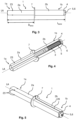
- Fig. 1 shows a view
- Fig. 2 shows an exploded view of a polygonal pin 1 according to the invention.
- the polygonal pin 1 is elongated and has a longitudinal center axis LA and two longitudinal ends 1a and 1b axial with respect to the longitudinal center axis LA.
- the first longitudinal end 1a is designed for rotationally fixed connection to a window gear of a window mechanism of a window locking system and the second longitudinal end 1b is designed for rotationally fixed connection to a window handle of a window fitting of the window locking system, as will be explained below with reference to Fig. 13 and Fig. 14 is described in more detail.
- the polygonal pin 1 has a square cross-section transverse to the longitudinal center axis LA and is therefore a square pin.
- the polygonal pin 1 has a first partial pin 2a, which forms the first longitudinal end 1a, and a second partial pin 2b, which forms the second longitudinal end 1b.
- the first partial pin 2a is a solid body and the second partial pin 2b is a pot-shaped hollow body.
- the outer diameter or outer contour of the first partial pin 2a and the inner diameter or inner contour of the second partial pin 2b are shaped such that the first partial pin 2a is accommodated in the second partial pin 2b in an axially displaceable manner.
- an axial length L of the polygonal pin 1 can be changed, as will be explained below with reference to Fig. 3-5 and Fig. 6-8 is described in more detail.
- the outer diameter of the first partial pin 2a and the inner diameter of the second partial pin 2b can be, for example, 7 mm.
- the outer diameter of the second partial pin 2b can be, for example, 8 mm.
- the polygonal pin 1 has a return spring 3—here a helical spring—which is accommodated in the second partial pin 2b.
- the return spring 3 is axially clamped between a base 4 of the second partial pin 2b, which is aligned transversely to the longitudinal center axis LA, and the first partial pin 2a.
- the return spring 3 is thus supported on one side by the base 4 of the second partial pin 2b and on the other side by the first partial pin 2a.
- the return spring 3 is clamped when the first partial pin 2a is pushed into the second partial pin 2b and is released when the first partial pin 2a is pushed out of the second partial pin 2b.
- the polygonal pin 1 further comprises a stop pin 5, which is axially aligned and received in the second partial pin 2b.
- the stop pin 5 is fastened to the first partial pin 2a facing the second partial pin 2b or is screwed to the first partial pin 2a.
- the return spring 3 is arranged around the stop pin 5 in a space-saving manner.
- the stop pin 5 has a stop head 6, wherein the stop head 6 protrudes from the base 5 of the second partial pin 2b and strikes the base from the outside.
- the stop pin 5, together with the first partial pin 2a, is arranged axially displaceably in the second partial pin 2b, so that the stop pin 5 can protrude from the base 4 of the second partial pin 2b or can strike axially with its stop head 6 against the base 4 of the second partial pin 2b.
- the stop pin 5 prevents the first partial pin 2a from being pushed out too far from the second partial pin 2b when the return spring 3 is released.
- the stop pin 5 thus determines the maximum and minimum axial length of the polygonal pin 1, as shown below with reference to Fig. 3-5 and Fig. 6-8 is described in more detail.
- the first partial pin 2a also has several stop formations 23 facing away from the second partial pin 2b or facing the first longitudinal end 1a of the polygonal pin 1.
- the stop formations 23 prevent excessive axially pushing the first partial pin 2a into a window gear of the window mechanism of the window locking system, as shown below with reference to Fig. 13 and Fig. 14 is described in more detail.
- the second partial pin 2b further has a circumferential and radially outwardly directed stop flange 7 facing the first partial pin 2a.
- the stop flange 7 is designed for the one-sided axial fixing of the polygonal pin 1 in a window locking element, as will be described below with reference to Fig. 9-10 is described in more detail.
- Fig. 3 shows a side view
- Fig. 4 shows a partial sectional view
- Fig. 5 shows a view of the polygonal pin 1 according to the invention in a first final state.
- the polygonal pin 1 has a maximum axial length L MAX .
- the axial length L of the polygonal pin 1 is defined between its two longitudinal ends 1a and 1b or between the axial end of the first partial pin 2a facing away from the second partial pin 2b and the axial end of the second partial pin 2b facing away from the first partial pin 2a or the bottom 4 of the second partial pin 2b.
- the first partial pin 2a protrudes from the second partial pin 2b to a maximum extent or to a maximum distance D MAX .
- the return spring 3 is maximally relaxed and the stop head 6 of the stop pin 5 strikes from the outside against the bottom 4 of the second partial pin 2b.
- Fig. 6 shows a side view
- Fig. 7 shows a partial sectional view
- Fig. 8 shows a view of the polygonal pin 1 according to the invention in a second final state.
- the polygonal pin 1 has a minimum axial length L MIN .
- the first partial pin 2a protrudes minimally, or to a minimum distance D MIN , from the second partial pin 2b.
- the return spring 3 is maximally clamped, and the stop pin 5 protrudes maximally from the second partial pin 2b.
- the polygonal pin 1 can have several intermediate states between the first final state and the second final state. In each intermediate state, the polygonal pin 1 can have an axial length L between the maximum length L MAX and the minimum length L MIN .
- the first partial pin 2a can therefore protrude from the second partial pin 2b to any distance between the maximum distance D MAX and the minimum distance D MIN .
- Fig. 9 and Fig. 10 show views of a device 8 according to the invention with the polygonal pin 1 according to the invention and a window locking element 9.
- Fig. 11 shows a partially exploded view of the device 8 according to the invention.
- the window locking element 9 has a support piece 10 and a locking unit 11.
- the polygonal pin 1 is arranged in the locking unit 11 and the locking unit 11 is arranged in the support piece 10 in a rotationally fixed manner.
- the polygonal pin 1 is rotatably connected to the support piece 10 and can be locked, for example, in 90° or 45° increments.
- the increments mentioned here are purely exemplary. In principle, increments with other increments are also conceivable.
- the polygonal pin 1 is arranged in a receiving opening 12 of the locking unit 11 via its stop flange 7 in a manner that is axially fixed on one side and is connected to the locking unit 11 via its contour in a rotationally fixed manner.
- two screw openings 13 are formed in the support piece 10, which are provided for fastening the window locking element 9 and thus the device 8 to a window frame.
- Fig. 12 shows an exploded view of the device 8 according to the invention as part of a window fitting 24 of a window locking system 20.
- the window fitting 24 of the window locking system 20 comprises, in addition to the device 8 according to the invention, two screws 15, a cover plate 17 and a ring 18.
- the device 8 also comprises a window handle 14 and a grub screw 16.
- the window locking element 9 of the device 8 can be used when mounting the window fitting 24 of the window locking system 20 on a window frame of a window - see Fig. 13 and Fig. 14 - be screwed to the window frame using screws 15.
- the screws 15 extend through the screw holes 13 in the support piece 10 to the window frame.
- the cover plate 17 covers the window locking element 9 and thus the screws 15 to the outside.
- the window handle 14 is connected in a rotationally fixed manner to the second partial pin 2b or to the second axial longitudinal end 1b of the polygonal pin 1 via its contour, and the grub screw 16 connects the window handle 14 axially fixedly to the polygonal pin 1.
- the ring 18 lies between the cover plate 17 and the window handle 14 and simplifies the rotation of the window handle 14 with respect to the cover plate 17.
- Fig. 13 and Fig. 14 show sectional views of the window locking system 20 mounted on different windows 19a and 19b with the device 8 according to the invention.
- the window locking system 20 has a window mechanism 25 with a window gear 21 and the window fitting 24 has the window handle 14, the screws 15, the grub screw 16, the cover plate 17, the ring 18 and the device 8 according to the invention with the polygonal pin 1 according to the invention.
- the respective window 19a and 19b has a window frame 22 on which the window locking system 20 is mounted.
- the window locking element 9 of the device 8 is screwed to the window frame 22 via the screws 15 and the polygonal pin 1 of the device 8 projects with its first axial longitudinal end 1a through the respective window frame 22.
- the polygonal pin 1 is connected to the window gear 21 at its first longitudinal end 1a and to the window handle 14 at its second longitudinal end 1b via the grub screw 16.
- the cover plate 17 is firmly connected to the support piece 10 of the window locking element 9, and the ring 18 lies radially between the window handle 14 and the cover plate 17.
- the window gear 21 on the window 19a in Fig. 13 a smaller axial distance to the window handle 14 or to the locking unit 11 of the device 8 than the window gear 21 on the window 19b in Fig. 14 on.
- Fig. 13 The smaller axial distance between the window gear 21 and the window handle 14 or the locking unit 11 of the device 8 is compensated for by the first partial pin 2a being pushed maximally into the second partial pin 2a.
- the polygonal pin 1 is therefore in the second state, and the first partial pin 2a protrudes a minimum distance D MIN from the second partial pin 2b.
- the polygonal pin 1 has the minimum axial length L MIN .
- the stop pin 5 protrudes axially 1 from the second partial pin 2b at the second longitudinal end 1a of the polygonal pin and into the window handle 14.
- Fig. 14 The greater axial distance between the window gear 21 and the window handle 14 or the locking unit 11 of the device 8 is compensated for by the first partial pin 2a being pushed out of the second partial pin 2b to the maximum extent.
- the polygonal pin 1 is therefore in the first state, and the first partial pin 2a protrudes a maximum distance D MAX from the second partial pin 2b.
- the polygonal pin 1 has the maximum axial length L MAX .
- the stop pin 5 is completely accommodated in the second partial pin 2b.
- the described adjustment of the axial length L of the polygonal pin 1 takes place automatically during the assembly of the window fitting 24 of the window locking system 20 on the windows 19a and 19b.
- the device 8 with the polygonal pin 1 is pushed into the window gear 21 until the first partial pin 2a axially abuts the window gear 21 via its stop formations 23. If the window locking element 9 of the device 8 has not yet reached the window frame 22, then upon further axial displacement of the device 8 towards the window gear 21, the partial pin 2a is pushed into the partial pin 2b until the window locking element 9 reaches the window frame 22 and can be fastened to the window frame 22.
- the length L of the polygonal pin 1 can be any length between the maximum length L MAX and the minimum length L MIN and can be adjusted automatically. This advantageously reduces the additional effort required to install the window fitting 24 of the window locking system 20 on the windows 19a and 19b or on the differing window mechanisms 25 of the window locking system 20.
- the second partial pin 2b has an axially aligned notch 26 facing the first partial pin 2a.
- the notch 26 extends parallel to the longitudinal axis LA through the entire partial pin 2b and is axially continuous.
- the notch 26 enables a reduction in the cross-section of the second partial pin 2b.
- the second partial pin 2b can thereby be clamped in the window locking element 9.
- the first partial pin 2a can also be clamped into the second partial pin 2b via the grub screw 16.
- the second partial pin 2b can be arranged in the window locking element 9 and the first partial pin 2a in the second partial pin 2b, and thus all components can be arranged axially displaceably against one another.
Landscapes
- Engineering & Computer Science (AREA)
- Mechanical Engineering (AREA)
- Structural Engineering (AREA)
- Insertion Pins And Rivets (AREA)
- Mutual Connection Of Rods And Tubes (AREA)
Description
- Die Erfindung betrifft einen Vielkantstift für einen Fensterbeschlag eines Fensterschließsystems nach dem Oberbegriff des Anspruchs 1. Die Erfindung betrifft auch eine Vorrichtung für einen Fensterbeschlag eines Fensterschließsystems mit dem Vielkantstift.
- Ein Fensterschließsystem weist üblicherweise eine Fenstermechanik und einen Fensterbeschlag auf. Die Fenstermechanik umfasst dabei alle in dem Fenster verbaute Bauteile wie beispielweise ein Fenstergetriebe und der Fensterbeschlag umfasst alle mit der Fenstermechanik von außen verbindbare Bauteile wie beispielweise einen Fenstergriff, ein Fensterrastelement und einen Vielkantstift. Dabei wird angestrebt, den Fensterbeschlag an abweichenden Fenstern mit abweichenden Fenstermechaniken montierbar zu gestalten. In dem Fensterschließsystem wird dabei das Fenstergetriebe mit dem Fenstergriff über den Vielkantstift drehfest verbunden. Wird der Fenstergriff betätigt, so verdreht sich der Vielkantstift in dem Fensterrastelement und betätigt das Fenstergetriebe. Entsprechend kann das Fenster verstellt - also geöffnet oder geschlossen - werden. Der Vielkantstift ist in dem Fensterrastelement rastbar aufgenommen und greift durch einen Fensterrahmen eines Fensters hindurch. Die Länge des Vielkantstifts ist dabei je nach der Ausgestaltung des Fensterrahmens und des Fenstergetriebes der Fenstermechanik unterschiedlich. Dadurch muss bei der Montage des Fensterbeschlags an der Fenstermechanik stets ein passender Vielkantstift ausgesucht und montiert werden. Das führt zu einem Mehraufwand bei der Montage.
-
EP 3 156 564 A1 offenbart einen Koppelstift zur antriebswirksamen Verbindung eines Handgriffs mit einem Getriebe, wobei die Länge des Koppelstifts entlang einer Längsachse des Koppelstifts variabel ist. -
EP 2 042 671 A2 offenbart eine Vorrichtung zur sicheren Anbringung eines Griff-Betätigungsstiftes an einer Befestigungsöffnung eines Griffs mit einem Adapter. Der Adapter umfasst dabei einen Befestigungsteil und einen Aufnahmeteil, der Mittel zum axial gesicherten Aufnehmen des Griff-Betätigungsstiftes aufweist. -
GB 655 528 A -
CN 108 104 598 A offenbart eine Pleuelstange eines Schlosses, die einen Schlosskörper und eine Handhabe aufweist. Dabei umfasst die Pleuelstange zwei Pleuelstangenstücke und ein elastisches Stück. Die Pleuelstangenstücke sind in axialer Richtung relativ zueinander beweglich und das elastische Stück ist zwischen den Pleuelstangenstücken angeordnet. -
DE 10 2016 123 052 A1 offenbart einen Drückerstift für eine Türdrückeranordnung mit einer Drückernuss zur Aufnahme des Drückerstifts. Dabei umfasst der Drückerstift ein erstes Stiftelement und ein zweites Stiftelement. - Die Aufgabe der Erfindung ist es daher, für einen Vielkantstift der gattungsgemäßen Art eine verbesserte oder zumindest alternative Ausführungsform anzugeben, bei der die beschriebenen Nachteile überwunden werden. Die Aufgabe der Erfindung ist es auch, eine Vorrichtung mit einem entsprechenden Fensterrastelement und dem Vielkantstift bereitzustellen.
- Diese Aufgabe wird erfindungsgemäß durch den Gegenstand der unabhängigen Ansprüche gelöst. Vorteilhafte Ausführungsformen sind Gegenstand der abhängigen Ansprüche.
- Der erfindungsgemäße Vielkantstift ist für einen Fensterbeschlag eines Fensterschließsystems vorgesehen bzw. ausgelegt. Der Vielkantstift ist gerade und länglich und weist eine Längsmittelachse auf. Ein erstes Längsende des Vielkantstifts ist dabei zum drehfesten Verbinden mit einem Fenstergetriebe und ein zweites Längsende des Vielkantstifts ist zum drehfesten Verbinden mit einem Fenstergriff vorgesehen bzw. ausgelegt. Erfindungsgemäß weist der Vielkantstift einen das erste Längsende bildenden ersten Teilstift und einen das zweite Längsende bildenden zweiten Teilstift auf. Dabei sind die beiden Teilstifte axial verschiebbar miteinander verbunden und dadurch ist eine durch den Abstand zwischen den Längsenden definierte axiale Länge des Vielkantstifts veränderlich. Mit anderen Worten kann der erste Teilstift in dem zweiten Teilstift stufenlos verschiebbar sein. Beim Vielkantstift handelt es sich vorzugsweise um einen Vierkantstift mit einem quadratischen Querschnitt.
- Im Zusammenhang mit der vorliegenden Erfindung sind die Begriffe "axial" und "radial" und "umlaufend" stets auf die Längsmittelachse des Vielkantstifts bezogen. Der Vielkantstift kann insbesondere ein Vierkantstift sein bzw. quer zur Längsmittelachse einen quadratischen oder rechteckigen Querschnitt aufweisen. Grundsätzlich kann der Vielkantstift auch einen abweichenden Querschnitt aufweisen. Das gilt auch für den ersten Teilstift und für den zweiten Teilstift, die zusammen den Vielkantstift abbilden. Der erste Teilstift und der zweite Teilstift können miteinander so verbunden sein, dass ein ungewünschtes Lösen des ersten Teilstifts und des zweiten Teilstifts voneinander ausgeschlossen ist.
- Das Fensterschließsystem kann dabei den Fensterbeschlag und eine Fenstermechanik umfassen. Die Fenstermechanik kann dabei alle in einem Fester verbaute Bauteile wie beispielweise ein Fenstergetriebe und der Fensterbeschlag kann alle mit der Fenstermechanik von außen verbindbare Bauteile wie beispielweise einen Fenstergriff und den erfindungsgemäßen Vielkantstift umfassen. Bei der Montage des Fensterbeschlags an einem Fenster kann die Fenstermechanik bzw. das Fenstergetriebe der Fenstermechanik mit dem Fenstergriff des Fensterbeschlags über den erfindungsgemäßen Vielkantstift verbunden werden. Die axiale Länge des erfindungsgemäßen Vielkantstifts kann bei der Montage des Fensterbeschlags an dem Fenster je nach Ausgestaltung seines Fensterrahmens und der Fenstermechanik des Fensterschließsystems angepasst sein. Dadurch kann der Fensterbeschlag des Fensterschließsystems mit dem erfindungsgemäßen Vielkantstift zur Montage an den Fenstern mit abweichenden Fensterrahmen und mit abweichenden Fenstermechaniken verwendet werden. Mit anderen Worten kann der Vielkantstift mit einem Fensterrastelement und mit einem Fenstergriff herstellerunabhängig eingebracht sein. Insbesondere kann der Vielkantstift in jedes beliebige marktübliche Fensterrastelement mit einer komplementären Vielkant-Aufnahme, vorzugsweise in eine Vierkant-Aufnahme, herstellerunabhängig in Kombination mit jedem marktüblichen Fenstergriff mit einer komplementären Vielkant-Aufnahme, vorzugsweise in eine Vierkant-Aufnahme, eingebracht sein. Entsprechend kann die Montage des Fensterbeschlags deutlich vereinfacht werden. Zudem kann der Bestand der notwendigen abweichend ausgestalteten Vielkantstifte reduziert werden.
- Der eine Teilstift ist erfindungsgemäß hohl ausgebildet und der andere Teilstift ist in dem einen Teilstift bereichsweise und axial verschiebbar aufgenommen. Ein Außendurchmesser des anderen Teilstifts kann zweckgemäß gleich oder geringfügig kleiner als ein Innendurchmesser des einen Teilstifts sein. Ein Außendurchmesser des anderen Teilstifts kann entsprechend kleiner als der Außendurchmesser des einen Teilstifts sein. Insbesondere können der andere Teilstift einen Außendurchmesser von 7 mm und der eine Teilstift einen Außendurchmesser von 8 mm aufweisen. Zum Verändern der axialen Länge des Vielkantstifts kann dann der andere Teilstift in den einen Teilstift hineingeschoben oder herausgeschoben werden. Bevorzugt ist eine Bauform, bei welcher der erste Teilstift in dem zweiten Teilstift aufgenommen ist. Es ist jedoch auch eine umgekehrte Bauform möglich, bei welcher der zweite Teilstift in dem ersten Teilstift aufgenommen ist. Wenn nachfolgend die bevorzugte Bauform näher erläutert wird, erfolgt dies stellvertretend für beide Ausführungsformen und gilt dementsprechend analog bzw. angepasst auch für die umgekehrte Bauform.
- Das Hineinschieben des ersten Teilstifts in den zweiten Teilstift und das Herausschieben des ersten Teilstifts aus dem zweiten Teilstift können axial begrenzt sein. Demnach kann eine maximale axiale Länge und eine minimale axiale Länge des Vielkantstifts fest definiert sein. Der Vielkantstift kann einen ersten Endzustand mit einer maximalen axialen Länge aufweisen, wobei in dem ersten Endzustand der erste Teilstift auf einen maximalen Abstand aus dem zweiten Teilstift herausgeschoben ist. Mit anderen Worten kann der erste Teilstift in dem ersten Zustand aus dem zweiten Teilstift maximal herausgeschoben sein. Entsprechend kann der Vielkantstift einen zweiten Endzustand mit einer minimalen axialen Länge aufweisen, wobei in dem zweiten Endzustand der erste Teilstift auf einen minimalen Abstand aus dem zweiten Teilstift herausgeschoben ist. Mit anderen Worten kann der erste Teilstift in dem zweiten Endzustand maximal in den zweiten Teilstift hineingeschoben sein. Zwischen dem ersten Endzustand und dem zweiten Endzustand kann der Vielkantstift mehrere Zwischenzustände aufweisen. In dem jeweiligen Zwischenzustand kann der Vielkantstift eine axiale Länge zwischen der maximalen Länge und der minimalen Länge aufweisen. Der erste Teilstift kann demnach auf einen beliebigen Abstand zwischen dem maximalen Abstand und dem minimalen Abstand aus dem zweiten Teilstift herausgeschoben sein.
- Der Vielkantstift weist zudem erfindungsgemäß eine Rückstellfeder auf und die Rückstellfeder ist in dem zweiten Teilstift aufgenommen. Mit anderen Worten kann die Rückstellfeder an dem zweiten Längsende des Vielkantstifts innerhalb des zweiten Teilstifts angeordnet sein. Dabei ist die Rückstellfeder zwischen einem quer zur Längsachse ausgerichteten Boden des zweiten Teilstifts und dem ersten Teilstift axial eingespannt. Die Rückstellfeder kann dadurch entgegen einer axialen Verschiebung des ersten Teilstifts zu dem zweiten axialen Längsende des Vielkantstifts bzw. entgegen dem Hineinschieben des ersten Teilstifts in den zweiten Teilstift bzw. entgegen dem Reduzieren der axialen Länge des Vielkantstifts wirken. Mit anderen Worten bringt die Rückstellfeder den Vielkantstift - sobald es nicht verhindert ist - aus dem zweiten Endzustand in den ersten Endzustand. Die Rückstellfeder kann insbesondere auf einen maximalen Überstand des ersten Teilstifts aus dem zweiten Teilstift vorgespannt sein. Dazu können die beiden Teilstifte des Vielkantstifts mittels einer Schraube entsprechend miteinander verbunden sein.
- Der Vielkantstift kann ferner einen axial ausgerichteten Anschlagstift mit einem Anschlagkopf aufweisen und der Anschlagstift kann in dem zweiten Teilstift aufgenommen bzw. in dem zweiten Teilstift angeordnet sein. Mit anderen Worten kann der Anschlagstift an dem zweiten Längsende des Vielkantstifts innerhalb des zweiten Teilstifts angeordnet sein. Der Anschlagstift kann dabei einseitig mit dem ersten Teilstift festverbunden sein und andersseitig mit dem Anschlagkopf aus einem quer zur Längsachse ausgerichteten Boden des zweiten Teilstifts herausragen. Der Anschlagkopf kann dabei mit dem Boden des zweiten Teilstifts axial hintergreifen bzw. an dem Boden des zweiten Teilstifts von außen anschlagen. Der Anschlagstift kann also die beiden Teilstifte verschiebbar miteinander verbinden und ein unerwünschtes Lösen der beiden Teilstifte voneinander verhindern. Der Anschlagstift kann dabei zusammen mit dem ersten Teilstift in dem zweiten Teilstift axial verschiebbar angeordnet sein. Die Rückstellfeder kann beispielweise eine Druckfeder sein und um den Anschlagstift herum angeordnet sein. Dadurch können die Rückstellfeder und der Anschlagstift platzsparend in dem zweiten Teilstift aufgenommen sein.
- Der Anschlagstift kann dabei entgegen der Rückstellfeder wirken. Ist der Anschlagstift an dem Boden des zweiten Teilstifts von außen angeschlagen, so ist die Rückstellfeder maximal entspannt und der Vielkantstift ist in dem ersten Zustand bzw. weist die maximale axiale Länge auf. Mit anderen Worten kann die Rückstellfeder nur auf die Länge des Anschlagstifts entspannen. Durch den Anschlag des Anschlagstifts an dem Boden des zweiten Teilstifts ist dabei ein weiteres Herausschieben des ersten Teilstifts aus dem zweiten Teilstift verhindert. Ist der erste Teilstift maximal in den zweiten Teilstift hineingeschoben, so ist die Rückstellfeder maximal eingespannt und der Anschlagstift ist aus dem zweiten Teilstift herausgeschoben. Der Vielkantstift befindet sich in dem zweiten Zustand und weist die minimale axiale Länge auf.
- Ist der Fensterbeschlag des Fensterschließsystems an dem Fenster bzw. an der Fenstermechanik des Fensterschließsystems montiert und ist der Vielkantstift mit dem Fenstergetriebe und dem Fenstergriff wirkend verbunden, so kann je nach der Längenanforderung der erste Teilstift in den zweiten Teilstift hineingeschoben sein und dadurch die axiale Länge des Vielkantstifts an die Ausgestaltung des Fensterrahmens und der Fenstermechanik des Fensterschließsystems angepasst sein. Dabei kann der Anschlagstift an dem zweiten axialen Längsende des Vielkantstifts aus dem zweiten Teilstift in den Fenstergriff hinein herausragen. Da die axiale Länge des zweiten Teilstifts technisch wenig relevant bzw. ausreichend frei anpassbar ist, kann das Herausschieben des Anschlagstifts durch die kürzere Länge des zweiten Teilstifts kompensiert sein. Dadurch ist der Vielkantstift mit einem beliebigen standardisierten Fenstergriff bzw. ohne jegliche Anpassung des Fenstergriffes nutzbar.
- Der zweite Teilstift weist erfindungsgemäß dem ersten Teilstift zugewandt einen umlaufenden und radial nach außen gerichteten Anschlagflansch auf. Der Vielkantstift kann dabei mit dem Anschlagflansch in einem Fensterrastelement einseitig axial befestigt sein. Mit anderen Worten kann der Anschlagflansch ein axiales Verschieben des Vielkantstifts in dem Fensterrastelement verhindern. Dadurch kann der Vielkantstift stets positionsgenau und sicher in dem Fensterrastelement angeordnet sein. Ist der Vielkantstift in dem Fensterrastelement positioniert, so kann der Anschlagflansch beispielweise ein Herausverschieben des Vielkantstifts aus dem Fensterrastelement beim montagebedingten Hineinschieben des ersten Teilstifts in den zweiten Teilstift verhindern.
- Der zweite Teilstift weist zudem erfindungsgemäß dem ersten Teilstift zugewandt wenigstens einen axial ausgerichteten Einschnitt zum radialen Einklemmen des Vielkantstifts in einem Fensterrastelement auf Dadurch kann der Vielkantstift in dem Fensterrastelement eingeklemmt sein und dadurch ein axiales Verschieben des Vielkantstifts aus dem Fensterrastelement verhindert werden. An dem Einschnitt kann insbesondere der Querschnitt des zweiten Teilstifts verkleinert und dadurch der zweite Teilstift in dem Fensterrastelement eingeklemmt werden. Der Einschnitt ermöglicht zudem eine formschlüssige Verbindung der beiden Teilstifte miteinander, sobald der Vielkantstift mittels eines axialen Verbindungselement - vorzugsweise einer Madenschraube - mit einem Fenstergriff verbunden ist. Durch das Verbindungselement kann der zweite Teilstift an den Einschnitt verformt und an den ersten Teilstift angepresst und dadurch in dem zweiten Teilstift eingeklemmt sein. Ist der Vielkantstift in dem Fensterrastelement eingeklemmt und das Verbindungselement fest mit dem Vielkantstift verbunden, so sind der erste Teilstift in dem zweiten Teilstift, der Fenstergriff an dem Vielkantstift und der Vielkantstift in dem Fensterrastelement axial und radial verschiebefest angeordnet. Dadurch sind nun alle Elemente zueinander fest und spielfrei miteinander verbunden.
- Der erste Teilstift und/oder der zweite Teilstift können quer zur Längsachse des Vielkantstifts einen durchgehenden und konstanten Querschnitt aufweisen. Ist der Vielkantstift ein Vierkantstift, so können der erste Teilstift und/oder der zweite Teilstift einen rechteckigen Querschnitt aufweisen. Dadurch können die Teilstifte vereinfacht hergestellt bzw. produziert sein bzw. komplexe Fertigungsverfahren vermieden bzw. umgegangen werden.
- Die Erfindung betrifft auch eine Vorrichtung oder eine Baugruppe für einen Fensterbeschlag eines Fensterschließsystems, wobei die Vorrichtung bzw. die Baugruppe einen Vielkantstift der vorstehend beschriebenen Art und ein Fensterrastelement aufweist. Das Fensterrastelement weist dabei ein Tragstück zum Festlegen des Fensterrastelements an einem Fensterrahmen eines Fensters und eine Rasteinheit zum Aufnehmen des Vielkantstifts auf. Die Rasteinheit ist dabei in dem Tragstück und der Vielkantstift ist in der Rasteinheit drehfest aufgenommen. Der Vielkantstift ist mittels der Rasteinheit mit dem Tragstück um die Längsmittelachse drehbar und in wenigstens zwei Positionen rastbar verbunden. Der Vielkantstift ist dabei wie oben beschrieben ausgebildet. Dabei kann der Vielkantstift in der Rasteinheit insbesondere mittels des Anschlagflansch positionsgenau angeordnet und mittels des Einschnitts verschiebefest eingeklemmt sein.
- Wie oben bereits beschrieben ist, kann der zweite Teilstift des Vielkantstifts dem ersten Teilstift des Vielkantstifts zugewandt wenigstens einen axial ausgerichteten Einschnitt aufweisen. Der Vielkantstift kann dann in dem Fensterrastelement im Bereich des axialen Einschnitts eingeklemmt sein. An dem Einschnitt kann insbesondere der Querschnitt des zweiten Teilstifts verkleinert werden, sodass der zweite Teilstift in dem Fensterrastelement einklemmbar ist.
- Die Vorrichtung kann zudem einen Fenstergriff und ein Verbindungselement, vorzugsweise eine Madenschraube, aufweisen. Der Fenstergriff kann mit dem Vielkantstift über das mit dem Vielkantstift verbundene Verbindungselement axial verschiebefest verbunden sein. Zudem kann der erste Teilstift in dem zweiten Teilstift durch das Verbindungselement im Bereich des axialen Einschnitts eingeklemmt sein. Der Fenstergriff und das Fensterrastelement können dann über den Vielkantstift mittelbar axial verschiebefest miteinander verbunden sein. Mit anderen Worten kann der Fenstergriff und das Fensterrastelement mit dem Vielkantstift axial verschiebefest verbunden sein und dadurch der Fenstergriff und das Fensterrastelement aneinander axial verschiebefest festgelegt sein.
- Wie oben bereits beschrieben ist, kann an dem Einschnitt der Querschnitt des zweiten Teilstifts verkleinert und dadurch der zweite Teilstift in dem Fensterrastelement und zusätzlich auch der erste Teilstift in dem zweiten Teilstift eingeklemmt werden. Der Einschnitt ermöglicht also eine formschlüssige Verbindung der beiden Teilstifte miteinander, sobald der Vielkantstift mittels des axialen Verbindungselements mit dem Fenstergriff verbunden ist. Durch das Verbindungselement kann der zweite Teilstift an dem Einschnitt verformt und an den ersten Teilstift angepresst und dadurch in dem zweiten Teilstift eingeklemmt sein.
- Weitere wichtige Merkmale und Vorteile der Erfindung ergeben sich aus den Unteransprüchen, aus den Zeichnungen und aus der zugehörigen Figurenbeschreibung anhand der Zeichnungen.
- Es versteht sich, dass die vorstehend genannten und die nachstehend noch zu erläuternden Merkmale nicht nur in der jeweils angegebenen Kombination, sondern auch in anderen Kombinationen oder in Alleinstellung verwendbar sind, ohne den Rahmen der vorliegenden durch die Ansprüche definierten Erfindung zu verlassen.
- Bevorzugte Ausführungsbeispiele der Erfindung sind in den Zeichnungen dargestellt und werden in der nachfolgenden Beschreibung näher erläutert, wobei sich gleiche Bezugszeichen auf gleiche oder ähnliche oder funktional gleiche Komponenten beziehen.
- Es zeigen, jeweils schematisch
- Fig. 1 und 2
- eine Ansicht und eine Explosionsansicht eines erfindungsgemäßen Vielkantstifts;
- Fig. 3 bis 5
- eine Seitenansicht, eine teilweise Schnittansicht und eine Ansicht des erfindungsgemäßen Vielkantstifts in einem ersten Endzustand;
- Fig. 6 bis 8
- eine Seitenansicht, eine teilweise Schnittansicht und eine Ansicht des erfindungsgemäßen Vielkantstifts in einem zweiten Endzustand;
- Fig. 9 und 10
- Ansichten einer erfindungsgemäßen Vorrichtung mit dem erfindungsgemäßen Vielkantstift und einem Fensterrastelement;
- Fig. 11
- eine teilweise Explosionsansicht der erfindungsgemäßen Vorrichtung;
- Fig. 12
- eine Explosionsansicht der erfindungsgemäßen Vorrichtung als einen Teil eines Fensterbeschlags eines Fensterschließsystems;
- Fig. 13 und 14
- Schnittansichten des an abweichenden Fenstern montierten Fensterschließsystems mit der erfindungsgemäßen Vorrichtung.
-
Fig. 1 zeigt eine Ansicht undFig. 2 zeigt eine Explosionsansicht eines erfindungsgemäßen Vielkantstifts 1. Der Vielkantstift 1 ist länglich und weist eine Längsmittelachse LA und zwei bezüglich der Längsmittelachse LA axiale Längsenden 1a und 1b auf. Das erste Längsende 1a ist zum drehfesten Verbinden mit einem Fenstergetriebe einer Fenstermechanik eines Fensterschließsystems und das zweite Längsende 1b ist zum drehfesten Verbinden mit einem Fenstergriff eines Fensterbeschlags des Fensterschließsystems ausgelegt, wie im Folgenden anhandFig. 13 und Fig. 14 näher beschrieben ist. Der Vielkantstift 1 weist in diesem Ausführungsbeispiel quer zur Längsmittelachse LA einen quadratischen Querschnitt auf und ist demnach ein Vierkantstift. - Der Vielkantstift 1 weist dabei einen ersten Teilstift 2a, der das erste Längsende 1a bildet, und einen zweiten Teilstift 2b, der das zweite Längsende 1b bildet. Der erste Teilstift 2a ist ein Vollkörper und der zweite Teilstift 2b ist ein topfförmiger Hohlkörper. Der Außendurchmesser bzw. die Außenkontur des ersten Teilstifts 2a und der Innendurchmesser bzw. die Innenkontur des zweiten Teilstifts 2b sind derart geformt, dass der erste Teilstift 2a in dem zweiten Teilstift 2b axial verschiebbar aufgenommen ist. Dadurch ist eine axiale Länge L des Vielkantstifts 1 veränderbar, wie im Folgenden anhand
Fig. 3-5 undFig. 6-8 näher beschrieben ist. Der Außendurchmesser des ersten Teilstifts 2a und der Innendurchmesser des zweiten Teilstifts 2b können beispielweise 7 mm betragen. Der Außendurchmesser des zweiten Teilstifts 2b kann beispielweise 8 mm betragen. - Ferner weist der Vielkantstift 1 eine Rückstellfeder 3 - hier eine Schraubenfeder - auf, die in dem zweiten Teilstift 2b aufgenommen ist. Die Rückstellfeder 3 ist dabei zwischen einem quer zur Längsmittelachse LA ausgerichteten Boden 4 des zweiten Teilstifts 2b und dem ersten Teilstift 2a axial eingespannt. Die Rückstellfeder 3 stützt sich also einseitig an dem Boden 4 des zweiten Teilstifts 2b und andersseitig an dem ersten Teilstift 2a. Die Rückstellfeder 3 wird dabei beim Hineinschieben des ersten Teilstifts 2a in den zweiten Teilstift 2b eingespannt und beim Herausschieben des ersten Teilstifts 2a aus dem zweiten Teilstift 2b entspannt.
- Der Vielkantstift 1 umfasst ferner einen Anschlagstift 5, der axial ausgerichtet ist und in dem zweiten Teilstift 2b aufgenommen ist. Der Anschlagstift 5 ist dem zweiten Teilstift 2b zugewandt an dem ersten Teilstift 2a befestigt bzw. mit dem ersten Teilstift 2a verschraubt. Die Rückstellfeder 3 ist dabei um den Anschlagstift 5 platzsparend angeordnet. Der Anschlagstift 5 weist einen Anschlagkopf 6 auf, wobei der Anschlagkopf 6 aus dem Boden 5 des zweiten Teilstifts 2b herausragt und von außen an dem Boden anschlägt. Der Anschlagstift 5 ist zusammen mit dem ersten Teilstift 2a axial verschiebbar in dem zweiten Teilstift 2b angeordnet, so dass der Anschlagstift 5 aus dem Boden 4 des zweiten Teilstifts 2b herausragen oder mit seinem Anschlagkopf 6 an dem Boden 4 des zweiten Teilstifts 2b axial anschlagen kann. Der Anschlagstift 5 verhindert, dass beim Entspannen der Rückstellfeder 3 der erste Teilstift 2a aus dem zweiten Teilstift 2b zu weit herausgeschoben wird. Der Anschlagstift 5 legt dadurch die maximale und die minimale axiale Länge des Vielkantstifts 1 fest, wie im Folgenden anhand
Fig. 3-5 undFig. 6-8 näher beschrieben ist. - Der erste Teilstift 2a weist zudem von dem zweiten Teilstift 2b abgewandt bzw. dem ersten Längsende 1a des Vielkantstifts 1 zugewandt mehrere Anschlagausformungen 23 auf. Die Anschlagausformungen 23 verhindern dabei ein zu weites axiales Hineinschieben des ersten Teilstifts 2a in ein Fenstergetriebe der Fenstermechanik des Fensterschließsystems, wie im Folgenden anhand
Fig. 13 und Fig. 14 näher beschrieben ist. Der zweite Teilstift 2b weist ferner dem ersten Teilstift 2a zugewandt einen umlaufenden und radial nach außen gerichteten Anschlagflansch 7 auf. Der Anschlagflansch 7 ist zum einseitigen axialen Festlegen des Vielkantstifts 1 in einem Fensterrastelement ausgelegt, wie im Folgenden anhandFig. 9-10 näher beschrieben ist. -
Fig. 3 zeigt eine Seitenansicht,Fig. 4 zeigt eine teilweise Schnittansicht undFig. 5 zeigt eine Ansicht des erfindungsgemäßen Vielkantstifts 1 in einem ersten Endzustand. In dem ersten Endzustand weist der Vielkantstift 1 eine maximale axiale Länge LMAX auf. Die axiale Länge L des Vielkantstifts 1 ist dabei zwischen seinen beiden Längsenden 1a und 1b bzw. zwischen dem von dem zweiten Teilstift 2b abgewandten axialen Ende des ersten Teilstifts 2a und dem von dem ersten Teilstift 2a abgewandten axialen Ende des zweiten Teilstifts 2b bzw. dem Boden 4 des zweiten Teilstifts 2b definiert. In dem ersten Zustand ragt der erste Teilstift 2a maximal bzw. auf einen maximalen Abstand DMAX aus dem zweiten Teilstift 2b heraus. In dem ersten Zustand ist die Rückstellfeder 3 maximal entspannt und der Anschlagkopf 6 des Anschlagstifts 5 schlägt von außen an dem Boden 4 des zweiten Teilstifts 2b an. -
Fig. 6 zeigt eine Seitenansicht,Fig. 7 zeigt eine teilweise Schnittansicht undFig. 8 zeigt eine Ansicht des erfindungsgemäßen Vielkantstifts 1 in einem zweiten Endzustand. In dem zweiten Endzustand weist der Vielkantstift 1 eine minimale axiale Länge LMIN auf. In dem zweiten Zustand ragt der erste Teilstift 2a minimal bzw. auf einen minimalen Abstand DMIN aus dem zweiten Teilstift 2b heraus. In dem zweiten Zustand ist die Rückstellfeder 3 maximal eingespannt und der Anschlagstift 5 ragt aus dem zweiten Teilstift 2b maximal hinaus. - Bezugnehmend auf
Fig. 3-8 kann der Vielkantstift 1 zwischen dem ersten Endzustand und dem zweiten Endzustand mehrere Zwischenzustände aufweisen. In dem jeweiligen Zwischenzustand kann der Vielkantstift 1 eine axiale Länge L zwischen der maximalen Länge LMAX und der minimalen Länge LMIN aufweisen. Der erste Teilstift 2a kann demnach auf einen beliebigen Abstand zwischen dem maximalen Abstand DMAX und dem minimalen Abstand DMIN aus dem zweiten Teilstift 2b herausragen. -
Fig. 9 und Fig. 10 zeigen Ansichten einer erfindungsgemäßen Vorrichtung 8 mit dem erfindungsgemäßen Vielkantstift 1 und einem Fensterrastelement 9.Fig. 11 zeigt eine teilweise Explosionsansicht der erfindungsgemäßen Vorrichtung 8. Das Fensterrastelement 9 weist dabei ein Tragstück 10 und eine Rasteinheit 11 auf. Der Vielkantstift 1 ist in der Rasteinheit 11 und die Rasteinheit 11 ist in dem Tragstück 10 drehfest angeordnet. Mittels der Rasteinheit 11 ist der Vielkantstift 1 mit dem Tragstück 10 drehbar und beispielweise in 90°-Raster oder in 45°-Raster rastbar verbunden. Die hier genannten Raster sind rein beispielhaft. Grundsätzlich sind auch Raster mit anderen Rastwinkeln denkbar. Der Vielkantstift 1 ist dabei über seinen Anschlagflansch 7 axial einseitig verschiebefest in einer Aufnahmeöffnung 12 der Rasteinheit 11 angeordnet und über seine Kontur drehfest mit der Rasteinheit 11 verbunden. In dem Tragstück 10 sind zudem zwei Schraubenöffnungen 13 ausgeformt, die zum Befestigen des Fensterrastelements 9 und demnach der Vorrichtung 8 an einem Fensterrahmen eines Fensters vorgesehen sind. -
Fig. 12 zeigt eine Explosionsansicht der erfindungsgemäßen Vorrichtung 8 als einen Teil eines Fensterbeschlags 24 eines Fensterschließsystems 20. Der Fensterbeschlag 24 des Fensterschließsystems 20 umfasst neben der erfindungsgemäßen Vorrichtung 8 zwei Schrauben 15eine Abdeckplatte 17 und einen Ring 18. Die Vorrichtung 8 umfasst zudem einen Fenstergriff 14 und eine Madenschraube 16. Das Fensterrastelement 9 der Vorrichtung 8 kann bei der Montage des Fensterbeschlags 24 des Fensterschließsystems 20 an einem Fensterrahmen eines Fensters - siehe hierzuFig. 13 und Fig. 14 - über die Schrauben 15 mit dem Fensterrahmen verschraubt sein. Die Schrauben 15 greifen dabei über die Schraubenöffnungen 13 in dem Tragstück 10 zu dem Fensterrahmen hindurch. Die Abdeckplatte 17 deckt nach der Montage das Fensterrastelement 9 und dadurch die Schrauben 15 nach außen ab. Der Fenstergriff 14 ist nach der Montage mit dem zweiten Teilstift 2b bzw. mit dem zweiten axialen Längsende 1b des Vielkantstifts 1 über seine Kontur drehfest verbunden und die Madenschraube 16 verbindet den Fenstergriff 14 axialfest mit dem Vielkantstift 1. Der Ring 18 liegt nach der Montage zwischen der Abdeckplatte 17 und dem Fenstergriff 14 und vereinfacht das Verdrehen des Fenstergriffs 14 bezüglich der Abdeckplatte 17. -
Fig. 13 und Fig. 14 zeigen Schnittansichten des an abweichenden Fenstern 19a und 19b montierten Fensterschließsystems 20 mit der erfindungsgemäßen Vorrichtung 8. Das Fensterschließsystem 20 weist dabei eine Fenstermechanik 25 mit einem Fenstergetriebe 21 auf und der Fensterbeschlag 24 weist den Fenstergriff 14, die Schrauben 15, die Madenschraube 16, die Abdeckplatte 17, den Ring 18 und die erfindungsgemäße Vorrichtung 8 mit dem erfindungsgemäßen Vielkantstift 1 auf. Das jeweilige Fenster 19a und 19b weist einen Fensterrahmen 22 auf, an dem das Fensterschließsystem 20 montiert ist. Das Fensterrastelement 9 der Vorrichtung 8 ist dabei mit dem Fensterrahmen 22 über die Schrauben 15 verschraubt und der Vielkantstift 1 der Vorrichtung 8 ragt mit seinem ersten axialen Längsende 1a durch den jeweiligen Fensterrahmen 22 hindurch. Der Vielkantstift 1 ist dabei an seinem ersten Längsende 1a mit dem Fenstergetriebe 21 und an seinem zweiten Längsende 1b über die Madenschraube 16 mit dem Fenstergriff 14 drehfest verbunden. Die Abdeckplatte 17 ist mit dem Tragstück 10 des Fensterrastelements 9 festverbunden und der Ring 18 liegt radial zwischen dem Fenstergriff 14 und der Abdeckplatte 17. - Vergleichsweise weist das Fenstergetriebe 21 am Fenster 19a in
Fig. 13 einen kleineren axialen Abstand zu dem Fenstergriff 14 bzw. zu der Rasteinheit 11 der Vorrichtung 8 als das Fenstergetriebe 21 am Fenster 19b inFig. 14 auf. - In
Fig. 13 ist der kleinere axiale Abstand zwischen dem Fenstergetriebe 21 und dem Fenstergriff 14 bzw. der Rasteinheit 11 der Vorrichtung 8 dadurch kompensiert, dass der erste Teilstift 2a maximal in den zweiten Teilstift 2a hineingeschoben ist. Der Vielkantstift 1 ist also in dem zweiten Zustand und der erste Teilstift 2a ragt auf einen minimalen Abstand DMIN aus dem zweiten Teilstift 2b heraus. Der Vielkantstift 1 weist die minimale axiale Länge LMIN auf. Der Anschlagstift 5 ragt dabei an dem zweiten Längsende 1a des Vielkantstifts axial 1 aus dem zweiten Teilstift 2b hinaus und in den Fenstergriff 14 hinein. - In
Fig. 14 ist der größere axiale Abstand zwischen dem Fenstergetriebe 21 und dem Fenstergriff 14 bzw. der Rasteinheit 11 der Vorrichtung 8 dadurch kompensiert, dass der erste Teilstift 2a maximal aus dem zweiten Teilstift 2b herausgeschoben ist. Der Vielkantstift 1 ist also in dem ersten Zustand und der erste Teilstift 2a ragt auf einen maximalen Abstand DMAX aus dem zweiten Teilstift 2b heraus. Der Vielkantstift 1 weist die maximale axiale Länge LMAX auf. Der Anschlagstift 5 ist dabei vollständig in dem zweiten Teilstift 2b aufgenommen. - Vorteilhaft ist es dabei, dass die beschriebene Anpassung der axialen Länge L des Vielkantstifts 1 bei der Montage des Fensterbeschlags 24 des Fensterschließsystems 20 an den Fenstern 19a und 19b automatisch erfolgt. So wird die Vorrichtung 8 mit dem Vielkantstift 1 solange in das Fenstergetriebe 21 hineingeschoben, bis der erste Teilstift 2a über seine Anschlagausformungen 23 an dem Fenstergetriebe 21 axial anschlägt. Hat das Fensterrastelement 9 der Vorrichtung 8 den Fensterrahmen 22 noch nicht erreicht, so wird beim weiteren axialen Verschieben der Vorrichtung 8 zu dem Fenstergetriebe 21 der Teilstift 2a in den Teilstift 2b hineingeschoben, bis das Fensterrastelement 9 den Fensterrahmen 22 erreicht und an dem Fensterrahmen 22 befestigt werden kann. Die Länge L des Vielkantstifts 1 kann dabei zwischen der maximalen Länge LMAX und der minimalen Länge LMIN beliebig sein und automatisch eingestellt werden. Dadurch kann der Mehraufwand bei der Montage des Fensterbeschlags 24 des Fensterschließsystems 20 an den Fenstern 19a und 19b bzw. an den voneinander abweichenden Fenstermechaniken 25 des Fensterschließsystems 20 vorteilhaft reduziert werden.
- Bezugnehmend auf
Fig. 1 bis Fig. 12 weist der zweite Teilstift 2b dem ersten Teilstift 2a zugewandt einen axial ausgerichteten Einschnitt 26 auf. Der Einschnitt 26 geht dabei parallel zur Längsachse LA durch den gesamten Teilstift 2b durch und ist axial durchgehend. Der Einschnitt 26 ermöglicht dabei eine Verkleinerung des Querschnitts des zweiten Teilstifts 2b. Bezugnehmend aufFig. 9 bis Fig. 11 kann dadurch der zweite Teilstift 2b in dem Fensterrastelement 9 eingeklemmt werden. Bezugnehmend aufFig. 12 kann zudem über die Madenschraube 16 auch der erste Teilstift 2a in dem zweiten Teilstift 2b eingeklemmt werden. Dabei können der zweite Teilstift 2b in dem Fensterrastelement 9 und der erste Teilstift 2a in dem zweiten Teilstift 2b und dadurch alle Bauelemente axial verschiebefest aneinander angeordnet sein.
Claims (11)
- Vielkantstift (1) für einen Fensterbeschlag (24) eines Fensterschließsystems (20),- wobei der Vielkantstift (1) länglich ist und eine Längsmittelachse (LA) aufweist,- wobei der Vielkantstift (1) ein erstes Längsende (1a) zum drehfesten Verbinden mit einem Fenstergetriebe (21) und ein zweites Längsende (1b) zum drehfesten Verbinden mit einem Fenstergriff (14) aufweist,- wobei der Vielkantstift (1) einen das erste Längsende (1a) bildenden ersten Teilstift (2a) und einen das zweite Längsende (1b) bildenden zweiten Teilstift (2b) aufweist, und- wobei die beiden Teilstifte (2a, 2b) axial verschiebbar miteinander verbunden sind und dadurch eine durch den Abstand zwischen den Längsenden (1a, 1b) definierte axiale Länge (L) des Vielkantstifts (1) veränderlich ist,- wobei der zweite Teilstift (2b) hohl ausgebildet ist und der erste Teilstift (2a) in dem zweiten Teilstift (2b) bereichsweise und axial verschiebbar aufgenommen ist,- wobei der Vielkantstift (1) eine Rückstellfeder (3) aufweist und die Rückstellfeder (3) in dem zweiten Teilstift (2b) aufgenommen ist, und- wobei die Rückstellfeder (3) zwischen einem quer zur Längsachse (LA) ausgerichteten Boden (4) des zweiten Teilstifts (2b) und dem ersten Teilstift (2a) axial eingespannt ist,dadurch gekennzeichnet,- dass der zweite Teilstift (2b) dem ersten Teilstift (2a) zugewandt einen umlaufenden und radial nach außen gerichteten Anschlagflansch (7) zum einseitigen axialen Festlegen des Vielkantstifts (1) in einem Fensterrastelement (9) aufweist, und- dass der zweite Teilstift (2b) dem ersten Teilstift (2a) zugewandt wenigstens einen axial ausgerichteten Einschnitt (26) zum radialen Einklemmen des Vielkantstifts (1) in dem Fensterrastelement (9) aufweist.
- Vielkantstift nach Anspruch 1,
dadurch gezeichnet,- dass der Vielkantstift (1) einen ersten Endzustand mit einer maximalen axialen Länge (LMAX) aufweist, wobei in dem ersten Endzustand der erste Teilstift (2a) auf einen maximalen Abstand (DMAX) aus dem zweiten Teilstift (2b) herausgeschoben ist, und- dass der Vielkantstift (1) einen zweiten Endzustand mit einer minimalen axialen Länge (LMIN) aufweist, wobei in dem zweiten Endzustand der erste Teilstift (2a) auf einen minimalen Abstand (DMIN) aus dem zweiten Teilstift (2b) herausgeschoben ist. - Vielkantstift nach Anspruch 2,
dadurch gekennzeichnet,- dass der Vielkantstift (1) zwischen dem ersten Endzustand und dem zweiten Endzustand mehrere Zwischenzustände aufweist, und- dass der Vielkantstift (1) in dem jeweiligen Zwischenzustand eine axiale Länge (L) zwischen der maximalen Länge (LMAX) und der minimalen Länge (LMIN) aufweist. - Vielkantstift nach einem der Ansprüche 1 bis 3,
dadurch gekennzeichnet,- dass der Vielkantstift (1) einen axial ausgerichteten Anschlagstift (5) mit einem Anschlagkopf (6) aufweist und der Anschlagstift (5) in dem zweiten Teilstift (2a) aufgenommen ist, und- dass der Anschlagstift (5) einseitig mit dem ersten Teilstift (2a) festverbunden ist und andersseitig mit dem Anschlagkopf (6) aus einem quer zur Längsachse (LA) ausgerichteten Boden (4) des zweiten Teilstifts (2b) herausragt und mit diesem axial hintergreift. - Vielkantstift nach Anspruch 4,
dadurch gekennzeichnet,
dass die Rückstellfeder (3) eine Druckfeder ist und um den Anschlagstift (5) herum angeordnet ist. - Vielkantstift nach einem der vorangehenden Ansprüche,
dadurch gekennzeichnet,
dass die Rückstellfeder (3) auf einen maximalen Überstand des ersten Teilstifts (2a) aus dem zweiten Teilstift (2b) vorgespannt ist. - Vielkantstift nach einem der vorangehenden Ansprüche,
dadurch gekennzeichnet,
dass der erste Teilstift (2a) und/oder der zweite Teilstift (2b) quer zur Längsachse (LA) einen durchgehenden und konstanten Querschnitt aufweisen. - Vielkantstift nach einem der vorangehenden Ansprüche,
dadurch gekennzeichnet,
dass der erste Teilstift (2a) in dem zweiten Teilstift (2b) stufenlos verschiebbar ist. - Vorrichtung (8) für einen Fensterbeschlag (24) eines Fensterschließsystems (20) mit einem Vielkantstift (1) und einem Fensterrastelement (9),- wobei das Fensterrastelement (9) ein Tragstück (10) zum Festlegen des Fensterrastelements (9) an einem Fensterrahmen (22) eines Fensters (19a, 19b) und eine Rasteinheit (11) zum Aufnehmen des Vielkantstifts (1) aufweist,- wobei die Rasteinheit (11) in dem Tragstück (10) und der Vielkantstift (1) in der Rasteinheit (11) drehfest aufgenommen sind, und- wobei der Vielkantstift (1) mittels der Rasteinheit (11) mit dem Tragstück (10) um die Längsmittelachse (LA) drehbar und in wenigstens zwei Positionen rastbar verbunden ist,dadurch gekennzeichnet,
dass der Vielkantstift (1) nach einem der vorangehenden Ansprüche ausgebildet ist. - Vorrichtung nach Anspruch 9,
dadurch gekennzeichnet,- dass der zweite Teilstift (2b) des Vielkantstifts (1) dem ersten Teilstift (2a) des Vielkantstifts (1) zugewandt wenigstens einen axial ausgerichteten Einschnitt (26) aufweist, und- dass der Vielkantstift (1) in dem Fensterrastelement (9) im Bereich des axialen Einschnitts (26) eingeklemmt ist. - Vorrichtung nach Anspruch 10,
dadurch gekennzeichnet,- dass die Vorrichtung (8) einen Fenstergriff (14) und ein Verbindungselement, vorzugsweise eine Madenschraube (16), aufweist,- dass der Fenstergriff (14) mit dem Vielkantstift (1) über das mit dem Vielkantstift (1) verbundene Verbindungselement axial verschiebefest verbunden ist,- dass der erste Teilstift (2a) in dem zweiten Teilstift (2b) durch das Verbindungselement im Bereich des axialen Einschnitts (26) eingeklemmt ist, und- dass der Fenstergriff (14) und das Fensterrastelement (9) über den Vielkantstift (1) mittelbar axial verschiebefest miteinander verbunden sind.
Applications Claiming Priority (1)
| Application Number | Priority Date | Filing Date | Title |
|---|---|---|---|
| DE102022211083.8A DE102022211083A1 (de) | 2022-10-19 | 2022-10-19 | Vielkantstift |
Publications (3)
| Publication Number | Publication Date |
|---|---|
| EP4368798A1 EP4368798A1 (de) | 2024-05-15 |
| EP4368798C0 EP4368798C0 (de) | 2025-05-21 |
| EP4368798B1 true EP4368798B1 (de) | 2025-05-21 |
Family
ID=88417298
Family Applications (1)
| Application Number | Title | Priority Date | Filing Date |
|---|---|---|---|
| EP23203830.7A Active EP4368798B1 (de) | 2022-10-19 | 2023-10-16 | Vielkantstift |
Country Status (2)
| Country | Link |
|---|---|
| EP (1) | EP4368798B1 (de) |
| DE (1) | DE102022211083A1 (de) |
Family Cites Families (5)
| Publication number | Priority date | Publication date | Assignee | Title |
|---|---|---|---|---|
| GB655528A (en) * | 1948-11-29 | 1951-07-25 | Headley Townsend Backhouse | Improvements in or relating to door locks and latches |
| DE102007046538A1 (de) * | 2007-09-27 | 2009-04-02 | Dorma Gmbh + Co. Kg | Griffbefestigung und Beschlag mit Griffbefestigung |
| DE102015117330A1 (de) * | 2015-10-12 | 2017-04-13 | Maco Technologie Gmbh | Koppelstift |
| DE102016123052B4 (de) * | 2016-11-29 | 2023-11-23 | Dormakaba Deutschland Gmbh | Türdrückeranordnung sowie Verfahren zur Montage einer Türdrückeranordnung |
| CN108104598A (zh) * | 2017-12-27 | 2018-06-01 | 李浩远 | 一种锁的连接杆 |
-
2022
- 2022-10-19 DE DE102022211083.8A patent/DE102022211083A1/de active Pending
-
2023
- 2023-10-16 EP EP23203830.7A patent/EP4368798B1/de active Active
Also Published As
| Publication number | Publication date |
|---|---|
| EP4368798C0 (de) | 2025-05-21 |
| DE102022211083A1 (de) | 2024-04-25 |
| EP4368798A1 (de) | 2024-05-15 |
Similar Documents
| Publication | Publication Date | Title |
|---|---|---|
| WO2007087991A1 (de) | Montageeinheit für die befestigungsöse eines gurtschlosses | |
| WO2016177706A1 (de) | Möbelscharnier mit einem dämpfer und einer feder | |
| EP2107187A1 (de) | Beschlag für Fenster oder Türen | |
| WO2021175370A1 (de) | Stellantrieb mit einer drehmomentbegrenzungsvorrichtung | |
| EP1916367A2 (de) | Kraftfahrzeugtürscharnier | |
| EP1588006A1 (de) | Türfeststeller | |
| EP1588007A1 (de) | Türfeststeller | |
| DE102020128569B4 (de) | Neigungshebelbaugruppe | |
| EP4368798B1 (de) | Vielkantstift | |
| DE29722488U1 (de) | Vorreiberverschluß für dickwandige Türen, Klappen o.dgl. | |
| EP3957813B1 (de) | Antriebsvorrichtung und schiebetür | |
| DE102004009331A1 (de) | Betätigungsmechanismus für Bowdenzüge | |
| EP2024592A1 (de) | Band mit justierung | |
| EP1722050A1 (de) | Drehriegelschloss | |
| EP4001555B1 (de) | Betätigungshandhabe mit längenvariablem mitnehmer | |
| EP3085864B1 (de) | Schliesseinrichtung für eine tür oder klappe | |
| DE102022120478A1 (de) | Betätigungshandhabe | |
| EP0663498A1 (de) | Schliesszylinder | |
| WO2020244982A1 (de) | Gurtaufrollervorrichtung für ein kraftfahrzeug | |
| EP3822513B1 (de) | Aktor mit kompakter interner drehmomentabstützung | |
| EP3894301B1 (de) | Lenksäule für ein kraftfahrzeug und ein verfahren zum montieren | |
| DE102020134060A1 (de) | Betätigungshandhabe für rosettenlose fenster und türen | |
| EP2177696B1 (de) | Tür- oder Fensterbeschlag | |
| EP1922467B1 (de) | Band für türen, fenster oder dergleichen | |
| DE102024106159A1 (de) | Verschlussvorrichtung für eine Tür |
Legal Events
| Date | Code | Title | Description |
|---|---|---|---|
| PUAI | Public reference made under article 153(3) epc to a published international application that has entered the european phase |
Free format text: ORIGINAL CODE: 0009012 |
|
| STAA | Information on the status of an ep patent application or granted ep patent |
Free format text: STATUS: THE APPLICATION HAS BEEN PUBLISHED |
|
| AK | Designated contracting states |
Kind code of ref document: A1 Designated state(s): AL AT BE BG CH CY CZ DE DK EE ES FI FR GB GR HR HU IE IS IT LI LT LU LV MC ME MK MT NL NO PL PT RO RS SE SI SK SM TR |
|
| STAA | Information on the status of an ep patent application or granted ep patent |
Free format text: STATUS: REQUEST FOR EXAMINATION WAS MADE |
|
| 17P | Request for examination filed |
Effective date: 20241010 |
|
| RBV | Designated contracting states (corrected) |
Designated state(s): AL AT BE BG CH CY CZ DE DK EE ES FI FR GB GR HR HU IE IS IT LI LT LU LV MC ME MK MT NL NO PL PT RO RS SE SI SK SM TR |
|
| GRAP | Despatch of communication of intention to grant a patent |
Free format text: ORIGINAL CODE: EPIDOSNIGR1 |
|
| STAA | Information on the status of an ep patent application or granted ep patent |
Free format text: STATUS: GRANT OF PATENT IS INTENDED |
|
| INTG | Intention to grant announced |
Effective date: 20250107 |
|
| GRAS | Grant fee paid |
Free format text: ORIGINAL CODE: EPIDOSNIGR3 |
|
| GRAA | (expected) grant |
Free format text: ORIGINAL CODE: 0009210 |
|
| STAA | Information on the status of an ep patent application or granted ep patent |
Free format text: STATUS: THE PATENT HAS BEEN GRANTED |
|
| AK | Designated contracting states |
Kind code of ref document: B1 Designated state(s): AL AT BE BG CH CY CZ DE DK EE ES FI FR GB GR HR HU IE IS IT LI LT LU LV MC ME MK MT NL NO PL PT RO RS SE SI SK SM TR |
|
| REG | Reference to a national code |
Ref country code: GB Ref legal event code: FG4D Free format text: NOT ENGLISH |
|
| REG | Reference to a national code |
Ref country code: CH Ref legal event code: EP |
|
| REG | Reference to a national code |
Ref country code: DE Ref legal event code: R096 Ref document number: 502023001032 Country of ref document: DE |
|
| REG | Reference to a national code |
Ref country code: IE Ref legal event code: FG4D Free format text: LANGUAGE OF EP DOCUMENT: GERMAN |
|
| U01 | Request for unitary effect filed |
Effective date: 20250617 |
|
| U07 | Unitary effect registered |
Designated state(s): AT BE BG DE DK EE FI FR IT LT LU LV MT NL PT RO SE SI Effective date: 20250627 |
|
| PG25 | Lapsed in a contracting state [announced via postgrant information from national office to epo] |
Ref country code: ES Free format text: LAPSE BECAUSE OF FAILURE TO SUBMIT A TRANSLATION OF THE DESCRIPTION OR TO PAY THE FEE WITHIN THE PRESCRIBED TIME-LIMIT Effective date: 20250521 |
|
| PG25 | Lapsed in a contracting state [announced via postgrant information from national office to epo] |
Ref country code: GR Free format text: LAPSE BECAUSE OF FAILURE TO SUBMIT A TRANSLATION OF THE DESCRIPTION OR TO PAY THE FEE WITHIN THE PRESCRIBED TIME-LIMIT Effective date: 20250822 Ref country code: NO Free format text: LAPSE BECAUSE OF FAILURE TO SUBMIT A TRANSLATION OF THE DESCRIPTION OR TO PAY THE FEE WITHIN THE PRESCRIBED TIME-LIMIT Effective date: 20250821 |
|
| PG25 | Lapsed in a contracting state [announced via postgrant information from national office to epo] |
Ref country code: PL Free format text: LAPSE BECAUSE OF FAILURE TO SUBMIT A TRANSLATION OF THE DESCRIPTION OR TO PAY THE FEE WITHIN THE PRESCRIBED TIME-LIMIT Effective date: 20250521 |
|
| PG25 | Lapsed in a contracting state [announced via postgrant information from national office to epo] |
Ref country code: HR Free format text: LAPSE BECAUSE OF FAILURE TO SUBMIT A TRANSLATION OF THE DESCRIPTION OR TO PAY THE FEE WITHIN THE PRESCRIBED TIME-LIMIT Effective date: 20250521 |
|
| PG25 | Lapsed in a contracting state [announced via postgrant information from national office to epo] |
Ref country code: RS Free format text: LAPSE BECAUSE OF FAILURE TO SUBMIT A TRANSLATION OF THE DESCRIPTION OR TO PAY THE FEE WITHIN THE PRESCRIBED TIME-LIMIT Effective date: 20250821 |
|
| PG25 | Lapsed in a contracting state [announced via postgrant information from national office to epo] |
Ref country code: IS Free format text: LAPSE BECAUSE OF FAILURE TO SUBMIT A TRANSLATION OF THE DESCRIPTION OR TO PAY THE FEE WITHIN THE PRESCRIBED TIME-LIMIT Effective date: 20250921 |
|
| U20 | Renewal fee for the european patent with unitary effect paid |
Year of fee payment: 3 Effective date: 20251027 |
|
| PG25 | Lapsed in a contracting state [announced via postgrant information from national office to epo] |
Ref country code: SM Free format text: LAPSE BECAUSE OF FAILURE TO SUBMIT A TRANSLATION OF THE DESCRIPTION OR TO PAY THE FEE WITHIN THE PRESCRIBED TIME-LIMIT Effective date: 20250521 |
|
| PG25 | Lapsed in a contracting state [announced via postgrant information from national office to epo] |
Ref country code: CZ Free format text: LAPSE BECAUSE OF FAILURE TO SUBMIT A TRANSLATION OF THE DESCRIPTION OR TO PAY THE FEE WITHIN THE PRESCRIBED TIME-LIMIT Effective date: 20250521 |
|
| PG25 | Lapsed in a contracting state [announced via postgrant information from national office to epo] |
Ref country code: SK Free format text: LAPSE BECAUSE OF FAILURE TO SUBMIT A TRANSLATION OF THE DESCRIPTION OR TO PAY THE FEE WITHIN THE PRESCRIBED TIME-LIMIT Effective date: 20250521 |