EP4368458A2 - Electrical power supply device and method of operating same - Google Patents
Electrical power supply device and method of operating same Download PDFInfo
- Publication number
- EP4368458A2 EP4368458A2 EP24166900.1A EP24166900A EP4368458A2 EP 4368458 A2 EP4368458 A2 EP 4368458A2 EP 24166900 A EP24166900 A EP 24166900A EP 4368458 A2 EP4368458 A2 EP 4368458A2
- Authority
- EP
- European Patent Office
- Prior art keywords
- voltage
- output voltage
- device controller
- output
- input voltage
- Prior art date
- Legal status (The legal status is an assumption and is not a legal conclusion. Google has not performed a legal analysis and makes no representation as to the accuracy of the status listed.)
- Pending
Links
- 238000000034 method Methods 0.000 title claims description 17
- 238000004891 communication Methods 0.000 claims abstract description 21
- 238000001514 detection method Methods 0.000 claims description 8
- 230000006870 function Effects 0.000 description 6
- 230000001052 transient effect Effects 0.000 description 5
- 230000004044 response Effects 0.000 description 4
- 230000008859 change Effects 0.000 description 2
- 238000013461 design Methods 0.000 description 2
- 239000000446 fuel Substances 0.000 description 2
- 239000000463 material Substances 0.000 description 2
- 238000012986 modification Methods 0.000 description 2
- 230000004048 modification Effects 0.000 description 2
- 230000008901 benefit Effects 0.000 description 1
- 230000001413 cellular effect Effects 0.000 description 1
- 238000002485 combustion reaction Methods 0.000 description 1
- 230000001419 dependent effect Effects 0.000 description 1
- 238000010586 diagram Methods 0.000 description 1
- 238000005516 engineering process Methods 0.000 description 1
- 238000012360 testing method Methods 0.000 description 1
Images
Classifications
-
- H—ELECTRICITY
- H02—GENERATION; CONVERSION OR DISTRIBUTION OF ELECTRIC POWER
- H02M—APPARATUS FOR CONVERSION BETWEEN AC AND AC, BETWEEN AC AND DC, OR BETWEEN DC AND DC, AND FOR USE WITH MAINS OR SIMILAR POWER SUPPLY SYSTEMS; CONVERSION OF DC OR AC INPUT POWER INTO SURGE OUTPUT POWER; CONTROL OR REGULATION THEREOF
- H02M1/00—Details of apparatus for conversion
- H02M1/36—Means for starting or stopping converters
-
- G—PHYSICS
- G06—COMPUTING; CALCULATING OR COUNTING
- G06F—ELECTRIC DIGITAL DATA PROCESSING
- G06F1/00—Details not covered by groups G06F3/00 - G06F13/00 and G06F21/00
- G06F1/26—Power supply means, e.g. regulation thereof
- G06F1/266—Arrangements to supply power to external peripherals either directly from the computer or under computer control, e.g. supply of power through the communication port, computer controlled power-strips
-
- B—PERFORMING OPERATIONS; TRANSPORTING
- B60—VEHICLES IN GENERAL
- B60R—VEHICLES, VEHICLE FITTINGS, OR VEHICLE PARTS, NOT OTHERWISE PROVIDED FOR
- B60R16/00—Electric or fluid circuits specially adapted for vehicles and not otherwise provided for; Arrangement of elements of electric or fluid circuits specially adapted for vehicles and not otherwise provided for
- B60R16/02—Electric or fluid circuits specially adapted for vehicles and not otherwise provided for; Arrangement of elements of electric or fluid circuits specially adapted for vehicles and not otherwise provided for electric constitutive elements
- B60R16/03—Electric or fluid circuits specially adapted for vehicles and not otherwise provided for; Arrangement of elements of electric or fluid circuits specially adapted for vehicles and not otherwise provided for electric constitutive elements for supply of electrical power to vehicle subsystems or for
-
- H—ELECTRICITY
- H02—GENERATION; CONVERSION OR DISTRIBUTION OF ELECTRIC POWER
- H02J—CIRCUIT ARRANGEMENTS OR SYSTEMS FOR SUPPLYING OR DISTRIBUTING ELECTRIC POWER; SYSTEMS FOR STORING ELECTRIC ENERGY
- H02J7/00—Circuit arrangements for charging or depolarising batteries or for supplying loads from batteries
- H02J7/14—Circuit arrangements for charging or depolarising batteries or for supplying loads from batteries for charging batteries from dynamo-electric generators driven at varying speed, e.g. on vehicle
- H02J7/1446—Circuit arrangements for charging or depolarising batteries or for supplying loads from batteries for charging batteries from dynamo-electric generators driven at varying speed, e.g. on vehicle in response to parameters of a vehicle
-
- B—PERFORMING OPERATIONS; TRANSPORTING
- B60—VEHICLES IN GENERAL
- B60R—VEHICLES, VEHICLE FITTINGS, OR VEHICLE PARTS, NOT OTHERWISE PROVIDED FOR
- B60R16/00—Electric or fluid circuits specially adapted for vehicles and not otherwise provided for; Arrangement of elements of electric or fluid circuits specially adapted for vehicles and not otherwise provided for
- B60R16/02—Electric or fluid circuits specially adapted for vehicles and not otherwise provided for; Arrangement of elements of electric or fluid circuits specially adapted for vehicles and not otherwise provided for electric constitutive elements
- B60R16/023—Electric or fluid circuits specially adapted for vehicles and not otherwise provided for; Arrangement of elements of electric or fluid circuits specially adapted for vehicles and not otherwise provided for electric constitutive elements for transmission of signals between vehicle parts or subsystems
-
- G—PHYSICS
- G05—CONTROLLING; REGULATING
- G05B—CONTROL OR REGULATING SYSTEMS IN GENERAL; FUNCTIONAL ELEMENTS OF SUCH SYSTEMS; MONITORING OR TESTING ARRANGEMENTS FOR SUCH SYSTEMS OR ELEMENTS
- G05B15/00—Systems controlled by a computer
- G05B15/02—Systems controlled by a computer electric
-
- H—ELECTRICITY
- H02—GENERATION; CONVERSION OR DISTRIBUTION OF ELECTRIC POWER
- H02J—CIRCUIT ARRANGEMENTS OR SYSTEMS FOR SUPPLYING OR DISTRIBUTING ELECTRIC POWER; SYSTEMS FOR STORING ELECTRIC ENERGY
- H02J7/00—Circuit arrangements for charging or depolarising batteries or for supplying loads from batteries
- H02J7/0029—Circuit arrangements for charging or depolarising batteries or for supplying loads from batteries with safety or protection devices or circuits
- H02J7/0034—Circuit arrangements for charging or depolarising batteries or for supplying loads from batteries with safety or protection devices or circuits using reverse polarity correcting or protecting circuits
-
- H—ELECTRICITY
- H02—GENERATION; CONVERSION OR DISTRIBUTION OF ELECTRIC POWER
- H02M—APPARATUS FOR CONVERSION BETWEEN AC AND AC, BETWEEN AC AND DC, OR BETWEEN DC AND DC, AND FOR USE WITH MAINS OR SIMILAR POWER SUPPLY SYSTEMS; CONVERSION OF DC OR AC INPUT POWER INTO SURGE OUTPUT POWER; CONTROL OR REGULATION THEREOF
- H02M3/00—Conversion of dc power input into dc power output
- H02M3/02—Conversion of dc power input into dc power output without intermediate conversion into ac
- H02M3/04—Conversion of dc power input into dc power output without intermediate conversion into ac by static converters
- H02M3/10—Conversion of dc power input into dc power output without intermediate conversion into ac by static converters using discharge tubes with control electrode or semiconductor devices with control electrode
- H02M3/145—Conversion of dc power input into dc power output without intermediate conversion into ac by static converters using discharge tubes with control electrode or semiconductor devices with control electrode using devices of a triode or transistor type requiring continuous application of a control signal
- H02M3/155—Conversion of dc power input into dc power output without intermediate conversion into ac by static converters using discharge tubes with control electrode or semiconductor devices with control electrode using devices of a triode or transistor type requiring continuous application of a control signal using semiconductor devices only
- H02M3/156—Conversion of dc power input into dc power output without intermediate conversion into ac by static converters using discharge tubes with control electrode or semiconductor devices with control electrode using devices of a triode or transistor type requiring continuous application of a control signal using semiconductor devices only with automatic control of output voltage or current, e.g. switching regulators
- H02M3/158—Conversion of dc power input into dc power output without intermediate conversion into ac by static converters using discharge tubes with control electrode or semiconductor devices with control electrode using devices of a triode or transistor type requiring continuous application of a control signal using semiconductor devices only with automatic control of output voltage or current, e.g. switching regulators including plural semiconductor devices as final control devices for a single load
- H02M3/1582—Buck-boost converters
-
- H—ELECTRICITY
- H04—ELECTRIC COMMUNICATION TECHNIQUE
- H04L—TRANSMISSION OF DIGITAL INFORMATION, e.g. TELEGRAPHIC COMMUNICATION
- H04L12/00—Data switching networks
- H04L12/28—Data switching networks characterised by path configuration, e.g. LAN [Local Area Networks] or WAN [Wide Area Networks]
- H04L12/40—Bus networks
- H04L12/40006—Architecture of a communication node
- H04L12/40045—Details regarding the feeding of energy to the node from the bus
-
- H—ELECTRICITY
- H02—GENERATION; CONVERSION OR DISTRIBUTION OF ELECTRIC POWER
- H02J—CIRCUIT ARRANGEMENTS OR SYSTEMS FOR SUPPLYING OR DISTRIBUTING ELECTRIC POWER; SYSTEMS FOR STORING ELECTRIC ENERGY
- H02J2310/00—The network for supplying or distributing electric power characterised by its spatial reach or by the load
- H02J2310/40—The network being an on-board power network, i.e. within a vehicle
- H02J2310/46—The network being an on-board power network, i.e. within a vehicle for ICE-powered road vehicles
-
- H—ELECTRICITY
- H02—GENERATION; CONVERSION OR DISTRIBUTION OF ELECTRIC POWER
- H02J—CIRCUIT ARRANGEMENTS OR SYSTEMS FOR SUPPLYING OR DISTRIBUTING ELECTRIC POWER; SYSTEMS FOR STORING ELECTRIC ENERGY
- H02J7/00—Circuit arrangements for charging or depolarising batteries or for supplying loads from batteries
- H02J7/00032—Circuit arrangements for charging or depolarising batteries or for supplying loads from batteries characterised by data exchange
- H02J7/00034—Charger exchanging data with an electronic device, i.e. telephone, whose internal battery is under charge
-
- H—ELECTRICITY
- H04—ELECTRIC COMMUNICATION TECHNIQUE
- H04L—TRANSMISSION OF DIGITAL INFORMATION, e.g. TELEGRAPHIC COMMUNICATION
- H04L12/00—Data switching networks
- H04L12/28—Data switching networks characterised by path configuration, e.g. LAN [Local Area Networks] or WAN [Wide Area Networks]
- H04L12/40—Bus networks
- H04L2012/40208—Bus networks characterized by the use of a particular bus standard
- H04L2012/40215—Controller Area Network CAN
-
- H—ELECTRICITY
- H04—ELECTRIC COMMUNICATION TECHNIQUE
- H04L—TRANSMISSION OF DIGITAL INFORMATION, e.g. TELEGRAPHIC COMMUNICATION
- H04L12/00—Data switching networks
- H04L12/28—Data switching networks characterised by path configuration, e.g. LAN [Local Area Networks] or WAN [Wide Area Networks]
- H04L12/40—Bus networks
- H04L2012/40208—Bus networks characterized by the use of a particular bus standard
- H04L2012/40234—Local Interconnect Network LIN
-
- H—ELECTRICITY
- H04—ELECTRIC COMMUNICATION TECHNIQUE
- H04L—TRANSMISSION OF DIGITAL INFORMATION, e.g. TELEGRAPHIC COMMUNICATION
- H04L12/00—Data switching networks
- H04L12/28—Data switching networks characterised by path configuration, e.g. LAN [Local Area Networks] or WAN [Wide Area Networks]
- H04L12/40—Bus networks
- H04L2012/40267—Bus for use in transportation systems
- H04L2012/40273—Bus for use in transportation systems the transportation system being a vehicle
-
- Y—GENERAL TAGGING OF NEW TECHNOLOGICAL DEVELOPMENTS; GENERAL TAGGING OF CROSS-SECTIONAL TECHNOLOGIES SPANNING OVER SEVERAL SECTIONS OF THE IPC; TECHNICAL SUBJECTS COVERED BY FORMER USPC CROSS-REFERENCE ART COLLECTIONS [XRACs] AND DIGESTS
- Y02—TECHNOLOGIES OR APPLICATIONS FOR MITIGATION OR ADAPTATION AGAINST CLIMATE CHANGE
- Y02T—CLIMATE CHANGE MITIGATION TECHNOLOGIES RELATED TO TRANSPORTATION
- Y02T10/00—Road transport of goods or passengers
- Y02T10/60—Other road transportation technologies with climate change mitigation effect
- Y02T10/72—Electric energy management in electromobility
Definitions
- the invention generally relates to an electrical power supply device and method of operating the electrical power supply device.
- USB Universal Serial Bus
- USB has become a ubiquitous power socket for many consumer devices such as cellular telephones, digital media players and/or other hand-held devices.
- Users utilize USB to fulfil their requirements not only in terms of data but also to provide power to, or charge, their devices simply, often without the need to load a driver, in order to carry out "traditional" USB functions.
- USB Power Delivery (PD) Specification enables the maximum functionality of USB by providing more flexible power delivery, e.g., for battery charging, along with data over a single cable. Its aim is to operate with and build on the existing USB ecosystem.
- the USB Power Delivery Specification 3.0 is published by the USB Implementer's Forum, Inc and is incorporated by reference herein.
- USB PD device has imposed requirements for a USB PD device and other automotive electrical modules powered by the vehicle battery requires it to meet "Start/Stop" transient tests in which the vehicle battery voltage temporarily dips down to as low as 6 volts to simulate the vehicle cranking during a warm start. During this transient, the USB PD device is expected to continue to function with no disruption to the consumer experience. With only a 6 volt input voltage during the transient, it is not possible for a buck only DC-DC converter to maintain an output voltage higher than the input voltage, e.g., 9 volts, to the consumer device while being charged.
- a proposed innovative solution is to provide a signal from the vehicle to the USB PD device to indicate the power state of the vehicle.
- the vehicle voltage is expected to be typically in the 12-14V range and a buck only DC-DC converter can generate a 9 volt output used by the consumer charging device in a fast charge mode.
- the change in mode is communicated by a signal from the vehicle to a controller in the USB PD device and the USB PD device then renegotiates the charging contact with the consumer device to provide a 5 volt output voltage for normal charging operation.
- the buck converter When the car subsequently experiences a crank cycle transient, the buck converter is able to maintain the 5 volt output without interrupting the charging session. After the engine starts and returns to the run mode, the USB PD device is again notified via another signal and returns to a 9 volt output.
- This innovation provides offer a lower cost "entry level" PD solution to customers that are not interested in a full featured and higher cost USB PD device.
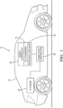
- Fig. 1 illustrates an electrical power supply device, e.g., a Universal Serial Bus (USB) power delivery (PD) device, hereinafter referred to as the PD device 10 that is designed for use in a motor vehicle 12.
- the PD device 10 may be used to support battery charging of USB enabled devices in the vehicle 12 (not shown).
- the PD device 10 includes a buck-only DC-DC power convertor, hereinafter referred to as the DC convertor 14, that receives an input voltage from a vehicle's electrical system.
- the output voltage can by one of at least two different voltages, e.g., a 9 volt output to support a fast USB charge rate or a 5 volt output to support a normal USB charge rate.
- the DC convertor 14, being a buck-only DC-DC power convertor is incapable of providing an output voltage that is greater than the input voltage.
- the PD device 10 also includes a device controller 16 that is in communication with the DC convertor 14.
- the device controller 16 has one or more processors and memory.
- the processors may be a microprocessors, application specific integrated circuits (ASIC), or built from discrete logic and timing circuits (not shown).
- Software instructions that program the processors may be stored in a non-volatile (NV) memory device (not shown).
- the NV memory device may be contained within the microprocessor or ASIC or it may be a separate device.
- Non-limiting examples of the types of NV memory that may be used include electrically erasable programmable read only memory (EEPROM), masked read only memory (ROM), and flash memory.
- the memory stores instructions which causes the device controller 16 to command the DC convertor 14 to output the higher output voltage, e.g., 9 volts, when the input voltage is equal to or greater than a threshold voltage and which causes the device controller 16 to command the DC convertor 14 to output the lower output voltage, e.g., 5 volts, when the input voltage is or will be less than the threshold voltage.
- the threshold voltage is greater than or equal to the higher output voltage.
- the PD device 10 also includes interface circuitry 18, such as a controller area network (CAN) transceiver, a local interconnect network (LIN) transceiver, a USB transceiver, and/or an input voltage detection circuit, e.g., an analog/digital convertor circuit, to allow the PD device 10 to establish electrical communication with other devices within the vehicle 12.
- interface circuitry 18 such as a controller area network (CAN) transceiver, a local interconnect network (LIN) transceiver, a USB transceiver, and/or an input voltage detection circuit, e.g., an analog/digital convertor circuit, to allow the PD device 10 to establish electrical communication with other devices within the vehicle 12.
- CAN controller area network
- LIN local interconnect network
- USB transceiver e.g., USB transceiver
- an input voltage detection circuit e.g., an analog/digital convertor circuit
- this circuit is in communication with the vehicle power supply, e.g. vehicle battery (not shown) and the device controller 16 and is configured to determine the input voltage to the PD device 10 from the vehicle battery and transmit that information to the device controller 16.
- the memory includes additional instructions which cause the device controller 16 to command the DC convertor 14 to output the higher output voltage, e.g. 9 volts, when the input voltage detection circuit determines that the input voltage is greater than the threshold voltage, e.g. 9.5 or 10 volts and which cause the device controller 16 to command the DC convertor 14 to output the lower output voltage, e.g. 5 volts, when the input voltage detection circuit determines that the input voltage is less than the threshold voltage.
- the PD device 10 is in communication with a start-stop controller 20 via the CAN transceiver, the LIN transceiver.
- the memory further includes instructions which cause the device controller 16 to command the DC convertor 14 to output the higher output voltage in accordance with the device controller 16 receiving a run signal from the start-stop controller 20.
- the reception of the run signal causes the device controller 16 to command the DC convertor 14 to output the lower output voltage in accordance with the device controller 16 receiving a stop signal from the start-stop controller 20.
- the run signal indicates that the IC engine 22 is running, therefore the input voltage will remain equal to or greater than the threshold voltage.
- the stop signal indicates that the IC engine 22 is not running and that the input voltage may drop to less than the threshold voltage, e.g. during a cranking transient.
- the PD device 10 is disposed within a USB port that is in communication with a USB hub.
- the memory includes instructions which cause the device controller 16 to command the DC convertor 14 to output the higher output voltage in accordance with the device controller 16 receiving a first USB signal from the USB hub indicating that the input voltage will remain equal to or greater than the threshold voltage and which cause the device controller 16 to command the DC convertor 14 to output the lower output voltage in accordance with the device controller 16 receiving a second signal from the USB hub indicating that the input voltage may drop to less than the threshold voltage.
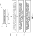
- Fig. 2 illustrates a method 100 of operating the PD device 10 which includes the DC convertor 14 and the device controller 16.
- the method 100 includes the following steps:
- the first and second output voltage are each less than the input voltage.
- the threshold voltage is greater than or equal to the first output voltage.
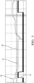
- the PD device 10 has negotiated a PD contract with a consumer device (not shown) at 27 watts i.e., output voltage 24 is 9Vand current capacity is 3A and a start-stop event 26 occurs in the vehicle 12, the PD device 10 will change the power negotiation from 27 watts to 15 watts, i.e., output voltage 24 is 5V and current capacity is 3A. Per the USB PD specifications the consumer device will choose the new 15 watt capability. After the stop-start event ends, the PD device 10 will renegotiate 27 watt capability and the consumer device will choose highest power needed.
- the input voltage 30 is monitored constantly by the PD device 10. If the input voltage 30 drops to the voltage threshold 32, the PD device 10 will negotiate a 15 watt only contract with the consumer device. If the input voltage 30 rises above the voltage threshold 32, PD device 10 will negotiate a 27 watt contract with the consumer device.
- the PD device 10 receives a start-stop signal, e.g., a CAN/LIN/discrete) signal from the vehicle 12 and negotiates a 15 watt contract with the consumer device when the stop-start signal is received, and negotiates a higher power, e.g., 27 watt, contract when the start-stop signal is no longer received or a signal indicating the completion of the start-stop event is received.
- a start-stop signal e.g., a CAN/LIN/discrete
- an electrical power supply device e.g., a USB PD device 10
- a method 100 of operating such a device is provided.
- the device provides the benefit of a USB PD device 10 that is capable of reliable operation in a motor vehicle 12 having a start-stop system at a lower cost than prior USB PD device designs.
- 'one or more' includes a function being performed by one element, a function being performed by more than one element, e.g., in a distributed fashion, several functions being performed by one element, several functions being performed by several elements, or any combination of the above.
- first, second, etc. are, in some instances, used herein to describe various elements, these elements should not be limited by these terms. These terms are only used to distinguish one element from another.
- a first contact could be termed a second contact, and, similarly, a second contact could be termed a first contact, without departing from the scope of the various described embodiments.
- the first contact and the second contact are both contacts, but they are not the same contact.
- the term “if' is, optionally, construed to mean “when” or “upon” or “in response to determining” or “in response to detecting,” depending on the context.
- the phrase “if it is determined” or “if [a stated condition or event] is detected” is, optionally, construed to mean “upon determining” or “in response to determining” or “upon detecting [the stated condition or event]” or “in response to detecting [the stated condition or event],” depending on the context.
- An electrical power supply device comprising: a DC-DC power convertor (14) receiving an input voltage (30) and producing a first output voltage (24) or a second output voltage (24) that is less than the first output voltage (24), the first and second output voltage (24) each less than the input voltage (30); and a device controller (16) in communication with the DC-DC power convertor (14), said device controller (16) having one or more processors and memory, wherein the memory includes instructions which causes the device controller (16) to command the DC-DC power convertor (14) to output the first output voltage (24) when the input voltage (30) is equal to or greater than a threshold voltage (32) and which causes the device controller (16) to command the DC-DC power convertor (14) to output the second output voltage (24) when the input voltage (30) is less than the threshold voltage (32).
- Example 2 The electrical power supply device (10) according to example 1, wherein the threshold voltage (32) is greater than or equal to the first output voltage (24).
- Example 3 The electrical power supply device (10) according to any of examples 1-2, wherein the DC-DC power convertor (14) is incapable of providing an output voltage (24) that is greater than the input voltage (30).
- Example 4 The electrical power supply device (10) according to example 3, wherein the electrical power supply device (10) further comprises an input voltage (30) detection circuit in communication with the device controller (16) and wherein the memory includes additional instructions which causes the device controller (16) to command the DC-DC power convertor (14) to output the second output voltage (24) when the input voltage (30) detection circuit determines that the input voltage (30) is less than the threshold voltage (32).
- Example 5 The electrical power supply device (10) according to example 3, wherein the electrical power supply device (10) is disposed within an automobile having a start-stop controller (20) in communication with the device controller (16), wherein the memory further includes instructions which cause the device controller (16) to command the DC-DC power convertor (14) to output the first output voltage (24) in accordance with the device controller (16) receiving a run signal from the start-stop controller (20), and wherein the memory additionally includes instructions which cause the device controller (16) to command the DC-DC power convertor (14) to output the second output voltage (24) in accordance with the device controller (16) receiving a stop signal from the start-stop controller (20).
- Example 6 The electrical power supply device (10) according to example 5, wherein the start-stop controller (20) is connected to the device controller (16) by a controller area network (CAN) communication bus.
- CAN controller area network
- Example 7 The electrical power supply device (10) according to example 5, wherein the start-stop controller (20) is connected to the device controller (16) by a local interconnect network (LIN) communication bus.
- LIN local interconnect network
- Example 8 The electrical power supply device (10) according to any of examples 5-7, wherein the run signal indicates that the input voltage (30) will remain equal to or greater than the threshold voltage (32) and the stop signal indicates that the input voltage (30) may drop to less than the threshold voltage (32).
- Example 9 The electrical power supply device (10) according to example 3, wherein the electrical power supply device (10) is disposed within a universal serial bus (USB) port in communication with a USB hub, wherein the memory further includes instructions which cause the device controller (16) to command the DC-DC power convertor (14) to output the first output voltage (24) in accordance with the device controller (16) receiving a first USB signal from the USB hub indicating that the input voltage (30) will remain equal to or greater than the threshold voltage (32), and wherein the memory additionally includes instructions which cause the device controller (16) to command the DC-DC power convertor (14) to output the second output voltage (24) in accordance with the device controller (16) receiving a second signal from the USB hub indicating that the input voltage (30) may drop to less than the threshold voltage (32).
- USB universal serial bus
- Example 10 The electrical power supply device (10) according to any preceding example, wherein the first output voltage (24) is about 9 volts and the second output voltage (24) is about 5 volts.
- Example 11 A method (100), comprising: at a device controller (16) and a DC-DC power convertor (14) in communication with the device controller (16), said device controller (16) having one or more processors and memory: receiving (102) an input voltage (30); receiving (104) a signal indicative of whether the input voltage (30) is equal to, greater than, or less than a threshold voltage (32); producing (106) a first output voltage (24) via the DC-DC power convertor (14) in accordance with the device controller (16) determining that the input voltage (30) is equal to the threshold voltage (32); producing (108) the first output voltage (24) via the DC-DC power convertor (14) in accordance with the device controller (16) determining that the input voltage (30) is greater than the threshold voltage (32); and producing (110) a second output voltage (24) via the DC-DC power convertor (14) which is less than the first output voltage (24) in accordance with the device controller (16) determining that the input voltage (30) is less than the threshold voltage (32), wherein the first and second output voltage (24) are each less than the input voltage
- Example 12 The method (100) according to example 11, wherein the threshold voltage (32) is greater than or equal to the first output voltage (24).
- Example 13 The method (100) according to any of examples 11-12, wherein the DC-DC power convertor (14) is incapable of providing an output voltage (24) that is greater than the input voltage (30).
- Example 14 The method (100) according to any of examples 11-13, wherein the first output voltage (24) is about 9 volts and the second output voltage (24) is about 5 volts.
Landscapes
- Engineering & Computer Science (AREA)
- Power Engineering (AREA)
- Mechanical Engineering (AREA)
- General Engineering & Computer Science (AREA)
- Physics & Mathematics (AREA)
- General Physics & Mathematics (AREA)
- Theoretical Computer Science (AREA)
- Automation & Control Theory (AREA)
- Computer Hardware Design (AREA)
- Computer Networks & Wireless Communication (AREA)
- Signal Processing (AREA)
- Charge And Discharge Circuits For Batteries Or The Like (AREA)
- Direct Current Feeding And Distribution (AREA)
- Dc-Dc Converters (AREA)
- Electric Propulsion And Braking For Vehicles (AREA)
Applications Claiming Priority (2)
| Application Number | Priority Date | Filing Date | Title |
|---|---|---|---|
| US15/954,851 US10635150B2 (en) | 2018-04-17 | 2018-04-17 | Electrical power supply device and method of operating same |
| EP19164904.5A EP3557723B1 (en) | 2018-04-17 | 2019-03-25 | Electrical power supply device and method of operating same |
Related Parent Applications (2)
| Application Number | Title | Priority Date | Filing Date |
|---|---|---|---|
| EP19164904.5A Division EP3557723B1 (en) | 2018-04-17 | 2019-03-25 | Electrical power supply device and method of operating same |
| EP19164904.5A Division-Into EP3557723B1 (en) | 2018-04-17 | 2019-03-25 | Electrical power supply device and method of operating same |
Publications (2)
| Publication Number | Publication Date |
|---|---|
| EP4368458A2 true EP4368458A2 (en) | 2024-05-15 |
| EP4368458A3 EP4368458A3 (en) | 2024-07-31 |
Family
ID=65911087
Family Applications (2)
| Application Number | Title | Priority Date | Filing Date |
|---|---|---|---|
| EP24166900.1A Pending EP4368458A3 (en) | 2018-04-17 | 2019-03-25 | Electrical power supply device and method of operating same |
| EP19164904.5A Active EP3557723B1 (en) | 2018-04-17 | 2019-03-25 | Electrical power supply device and method of operating same |
Family Applications After (1)
| Application Number | Title | Priority Date | Filing Date |
|---|---|---|---|
| EP19164904.5A Active EP3557723B1 (en) | 2018-04-17 | 2019-03-25 | Electrical power supply device and method of operating same |
Country Status (5)
| Country | Link |
|---|---|
| US (1) | US10635150B2 (zh) |
| EP (2) | EP4368458A3 (zh) |
| JP (1) | JP6727369B2 (zh) |
| KR (1) | KR102209317B1 (zh) |
| CN (1) | CN110391740B (zh) |
Families Citing this family (4)
| Publication number | Priority date | Publication date | Assignee | Title |
|---|---|---|---|---|
| US11342705B2 (en) * | 2018-04-17 | 2022-05-24 | Aptiv Technologies Limited | Electrical power supply device and method of operating same |
| US11652315B2 (en) | 2018-04-17 | 2023-05-16 | Aptiv Technologies Limited | Electrical power supply device |
| US11119548B2 (en) * | 2020-01-08 | 2021-09-14 | Cypress Semiconductor Corporation | Dynamic power throttling based on system conditions in USB Type-C power delivery (USB-C/PD) ecosystem |
| CN116800140A (zh) * | 2022-03-18 | 2023-09-22 | 台达电子工业股份有限公司 | 直流马达驱动系统及方法 |
Family Cites Families (17)
| Publication number | Priority date | Publication date | Assignee | Title |
|---|---|---|---|---|
| JP3892528B2 (ja) | 1997-05-19 | 2007-03-14 | 日産自動車株式会社 | ハイブリッド電気自動車の補助電源バッテリ充電制御装置 |
| JP3637876B2 (ja) * | 2001-04-05 | 2005-04-13 | トヨタ自動車株式会社 | Dc−dcコンバータの制御装置 |
| DE102004023620B4 (de) | 2004-05-10 | 2018-01-04 | Volkswagen Ag | Verfahren und Vorrichtung zum Energiemanagement in einem Kraftfahrzeug |
| JP5234139B2 (ja) * | 2010-05-20 | 2013-07-10 | 株式会社日本自動車部品総合研究所 | 無線通信装置 |
| KR101987992B1 (ko) * | 2012-10-24 | 2019-06-11 | 현대모비스 주식회사 | 충격 감지 기능을 이용한 차량용 영상 녹화 장치 및 그 방법 |
| KR101494412B1 (ko) * | 2013-02-08 | 2015-02-23 | 주식회사 피엘케이 테크놀로지 | 다채널을 통한 복합 원격시동시스템 |
| TWI507873B (zh) * | 2013-07-29 | 2015-11-11 | Hon Hai Prec Ind Co Ltd | 電源適配器及電子裝置 |
| US20150069956A1 (en) * | 2013-09-09 | 2015-03-12 | Apple Inc. | Universal power adapter |
| US9444281B2 (en) * | 2014-01-03 | 2016-09-13 | Apple Inc. | Unified high power and low power battery charger |
| US9590503B2 (en) * | 2014-09-17 | 2017-03-07 | Monolithic Power Systems, Inc. | Switching converter and associated discharge method |
| EP3043442A1 (en) * | 2015-01-12 | 2016-07-13 | Li, Dong-Sheng | Hub having complex power converters |
| US9473028B1 (en) * | 2015-04-29 | 2016-10-18 | Hamilton Sundstrand Corporation | Systems and methods for controlling power converters |
| JP6446325B2 (ja) * | 2015-05-08 | 2018-12-26 | オムロンオートモーティブエレクトロニクス株式会社 | 電源供給装置 |
| US10044209B2 (en) * | 2015-12-01 | 2018-08-07 | GM Global Technology Operations LLC | Method and apparatus for charging a high-voltage battery assembly |
| JP6777849B2 (ja) * | 2016-07-13 | 2020-10-28 | ミツミ電機株式会社 | 車載用充電コネクタの充電制御回路、車載用充電コネクタ、及び外部機器への車両内データ転送・充電システム |
| JP6719332B2 (ja) * | 2016-08-24 | 2020-07-08 | Fdk株式会社 | 充電装置 |
| CN107786088B (zh) * | 2016-08-29 | 2021-07-09 | 中兴通讯股份有限公司 | 电源电路、电源电路控制方法和存储介质 |
-
2018
- 2018-04-17 US US15/954,851 patent/US10635150B2/en active Active
-
2019
- 2019-03-25 EP EP24166900.1A patent/EP4368458A3/en active Pending
- 2019-03-25 EP EP19164904.5A patent/EP3557723B1/en active Active
- 2019-04-10 KR KR1020190041913A patent/KR102209317B1/ko active IP Right Grant
- 2019-04-15 JP JP2019076870A patent/JP6727369B2/ja active Active
- 2019-04-16 CN CN201910302561.XA patent/CN110391740B/zh active Active
Also Published As
| Publication number | Publication date |
|---|---|
| JP6727369B2 (ja) | 2020-07-22 |
| EP4368458A3 (en) | 2024-07-31 |
| CN110391740A (zh) | 2019-10-29 |
| US20190317581A1 (en) | 2019-10-17 |
| KR20190121248A (ko) | 2019-10-25 |
| EP3557723A1 (en) | 2019-10-23 |
| EP3557723B1 (en) | 2024-06-05 |
| KR102209317B1 (ko) | 2021-02-01 |
| CN110391740B (zh) | 2021-04-27 |
| JP2019198217A (ja) | 2019-11-14 |
| US10635150B2 (en) | 2020-04-28 |
Similar Documents
| Publication | Publication Date | Title |
|---|---|---|
| EP4368458A2 (en) | Electrical power supply device and method of operating same | |
| CN107985229B (zh) | 电池管理系统及其控制方法 | |
| CN102624312B (zh) | 混合变频发电机 | |
| EP3557724B1 (en) | Electrical power supply device and method of operating same | |
| EP2272722A2 (en) | Power source apparatus for vehicle | |
| WO2013054435A1 (ja) | 電気自動車用の充電装置 | |
| EP2660949A9 (en) | Recharging device for vehicle | |
| EP2773526A2 (en) | A dual energy storage system for micro hybrid vehicles | |
| WO2005123442A2 (en) | System and method for electrical energy switching and control | |
| US10882415B2 (en) | System and method of pre-charge testing to prevent misuse of electric vehicle charging station | |
| CN110192320B (zh) | 电源装置和电源系统 | |
| US9878625B2 (en) | Vehicle including charger and electronic control unit configured to control the charger, and control method for controlling charger of vehicle | |
| US11652315B2 (en) | Electrical power supply device | |
| US11342705B2 (en) | Electrical power supply device and method of operating same | |
| CN205750527U (zh) | 自动通电控制装置与系统 | |
| US10185380B1 (en) | Electrical power supply device and method of operating same | |
| US20180073479A1 (en) | Power supply device for vehicle | |
| US20150210177A1 (en) | Controlling device for electric vehicle charger | |
| EP3736177A1 (en) | A method for controlling a super capacitor module for a vehicle with a high voltage power source | |
| CN114362336A (zh) | 能量回收利用控制装置及控制方法 | |
| CN114123444A (zh) | 一种蓄电池的充放电控制方法、装置及相关设备 | |
| JPWO2013054435A1 (ja) | 電気自動車用の充電装置 |
Legal Events
| Date | Code | Title | Description |
|---|---|---|---|
| PUAI | Public reference made under article 153(3) epc to a published international application that has entered the european phase |
Free format text: ORIGINAL CODE: 0009012 |
|
| STAA | Information on the status of an ep patent application or granted ep patent |
Free format text: STATUS: THE APPLICATION HAS BEEN PUBLISHED |
|
| AC | Divisional application: reference to earlier application |
Ref document number: 3557723 Country of ref document: EP Kind code of ref document: P |
|
| AK | Designated contracting states |
Kind code of ref document: A2 Designated state(s): AL AT BE BG CH CY CZ DE DK EE ES FI FR GB GR HR HU IE IS IT LI LT LU LV MC MK MT NL NO PL PT RO RS SE SI SK SM TR |
|
| RAP1 | Party data changed (applicant data changed or rights of an application transferred) |
Owner name: APTIV TECHNOLOGIES AG |
|
| REG | Reference to a national code |
Ref country code: DE Ref legal event code: R079 Free format text: PREVIOUS MAIN CLASS: B60R0016030000 Ipc: H02J0007140000 |
|
| PUAL | Search report despatched |
Free format text: ORIGINAL CODE: 0009013 |
|
| AK | Designated contracting states |
Kind code of ref document: A3 Designated state(s): AL AT BE BG CH CY CZ DE DK EE ES FI FR GB GR HR HU IE IS IT LI LT LU LV MC MK MT NL NO PL PT RO RS SE SI SK SM TR |
|
| RIC1 | Information provided on ipc code assigned before grant |
Ipc: H02J 7/00 20060101ALN20240625BHEP Ipc: B60R 16/03 20060101ALI20240625BHEP Ipc: H02J 7/14 20060101AFI20240625BHEP |