EP3557724B1 - Electrical power supply device and method of operating same - Google Patents
Electrical power supply device and method of operating same Download PDFInfo
- Publication number
- EP3557724B1 EP3557724B1 EP19168163.4A EP19168163A EP3557724B1 EP 3557724 B1 EP3557724 B1 EP 3557724B1 EP 19168163 A EP19168163 A EP 19168163A EP 3557724 B1 EP3557724 B1 EP 3557724B1
- Authority
- EP
- European Patent Office
- Prior art keywords
- output voltage
- controller
- usb
- signal
- stop
- Prior art date
- Legal status (The legal status is an assumption and is not a legal conclusion. Google has not performed a legal analysis and makes no representation as to the accuracy of the status listed.)
- Active
Links
Images
Classifications
-
- H—ELECTRICITY
- H02—GENERATION; CONVERSION OR DISTRIBUTION OF ELECTRIC POWER
- H02J—ELECTRIC POWER NETWORKS; CIRCUIT ARRANGEMENTS OR SYSTEMS FOR SUPPLYING OR DISTRIBUTING ELECTRIC POWER; SYSTEMS FOR STORING ELECTRIC ENERGY
- H02J7/00—Circuit arrangements for charging or discharging batteries or for supplying loads from batteries
- H02J7/14—Circuit arrangements for charging or discharging batteries or for supplying loads from batteries for charging batteries from dynamo-electric generators driven at varying speed, e.g. on vehicle
- H02J7/1446—Circuit arrangements for charging or discharging batteries or for supplying loads from batteries for charging batteries from dynamo-electric generators driven at varying speed, e.g. on vehicle in response to parameters of a vehicle
-
- B—PERFORMING OPERATIONS; TRANSPORTING
- B60—VEHICLES IN GENERAL
- B60R—VEHICLES, VEHICLE FITTINGS, OR VEHICLE PARTS, NOT OTHERWISE PROVIDED FOR
- B60R16/00—Electric or fluid circuits specially adapted for vehicles and not otherwise provided for; Arrangement of elements of electric or fluid circuits specially adapted for vehicles and not otherwise provided for
- B60R16/02—Electric or fluid circuits specially adapted for vehicles and not otherwise provided for; Arrangement of elements of electric or fluid circuits specially adapted for vehicles and not otherwise provided for electric constitutive elements
- B60R16/023—Electric or fluid circuits specially adapted for vehicles and not otherwise provided for; Arrangement of elements of electric or fluid circuits specially adapted for vehicles and not otherwise provided for electric constitutive elements for transmission of signals between vehicle parts or subsystems
- B60R16/0231—Circuits relating to the driving or the functioning of the vehicle
- B60R16/0236—Circuits relating to the driving or the functioning of the vehicle for economical driving
-
- B—PERFORMING OPERATIONS; TRANSPORTING
- B60—VEHICLES IN GENERAL
- B60R—VEHICLES, VEHICLE FITTINGS, OR VEHICLE PARTS, NOT OTHERWISE PROVIDED FOR
- B60R16/00—Electric or fluid circuits specially adapted for vehicles and not otherwise provided for; Arrangement of elements of electric or fluid circuits specially adapted for vehicles and not otherwise provided for
- B60R16/02—Electric or fluid circuits specially adapted for vehicles and not otherwise provided for; Arrangement of elements of electric or fluid circuits specially adapted for vehicles and not otherwise provided for electric constitutive elements
- B60R16/03—Electric or fluid circuits specially adapted for vehicles and not otherwise provided for; Arrangement of elements of electric or fluid circuits specially adapted for vehicles and not otherwise provided for electric constitutive elements for supply of electrical power to vehicle subsystems or for
-
- G—PHYSICS
- G05—CONTROLLING; REGULATING
- G05B—CONTROL OR REGULATING SYSTEMS IN GENERAL; FUNCTIONAL ELEMENTS OF SUCH SYSTEMS; MONITORING OR TESTING ARRANGEMENTS FOR SUCH SYSTEMS OR ELEMENTS
- G05B19/00—Program-control systems
- G05B19/02—Program-control systems electric
- G05B19/04—Program control other than numerical control, i.e. in sequence controllers or logic controllers
- G05B19/042—Program control other than numerical control, i.e. in sequence controllers or logic controllers using digital processors
-
- B—PERFORMING OPERATIONS; TRANSPORTING
- B60—VEHICLES IN GENERAL
- B60Y—INDEXING SCHEME RELATING TO ASPECTS CROSS-CUTTING VEHICLE TECHNOLOGY
- B60Y2300/00—Purposes or special features of road vehicle drive control systems
- B60Y2300/18—Propelling the vehicle
- B60Y2300/18008—Propelling the vehicle related to particular drive situations
- B60Y2300/1805—Propelling the vehicle related to particular drive situations at stand still, e.g. engine in idling state
-
- B—PERFORMING OPERATIONS; TRANSPORTING
- B60—VEHICLES IN GENERAL
- B60Y—INDEXING SCHEME RELATING TO ASPECTS CROSS-CUTTING VEHICLE TECHNOLOGY
- B60Y2300/00—Purposes or special features of road vehicle drive control systems
- B60Y2300/18—Propelling the vehicle
- B60Y2300/192—Power-up or power-down of the driveline, e.g. start up of a cold engine
-
- G—PHYSICS
- G05—CONTROLLING; REGULATING
- G05B—CONTROL OR REGULATING SYSTEMS IN GENERAL; FUNCTIONAL ELEMENTS OF SUCH SYSTEMS; MONITORING OR TESTING ARRANGEMENTS FOR SUCH SYSTEMS OR ELEMENTS
- G05B2219/00—Program-control systems
- G05B2219/20—Pc systems
- G05B2219/25—Pc structure of the system
- G05B2219/25361—DC-DC convertor on board
-
- H—ELECTRICITY
- H02—GENERATION; CONVERSION OR DISTRIBUTION OF ELECTRIC POWER
- H02J—ELECTRIC POWER NETWORKS; CIRCUIT ARRANGEMENTS OR SYSTEMS FOR SUPPLYING OR DISTRIBUTING ELECTRIC POWER; SYSTEMS FOR STORING ELECTRIC ENERGY
- H02J2105/00—Networks for supplying or distributing electric power characterised by their spatial reach or by the load
- H02J2105/30—Networks for supplying or distributing electric power characterised by their spatial reach or by the load the load networks being external to vehicles, i.e. exchanging power with vehicles
- H02J2105/33—Networks for supplying or distributing electric power characterised by their spatial reach or by the load the load networks being external to vehicles, i.e. exchanging power with vehicles exchanging power with road vehicles
-
- H—ELECTRICITY
- H02—GENERATION; CONVERSION OR DISTRIBUTION OF ELECTRIC POWER
- H02J—ELECTRIC POWER NETWORKS; CIRCUIT ARRANGEMENTS OR SYSTEMS FOR SUPPLYING OR DISTRIBUTING ELECTRIC POWER; SYSTEMS FOR STORING ELECTRIC ENERGY
- H02J7/00—Circuit arrangements for charging or discharging batteries or for supplying loads from batteries
- H02J7/40—Circuit arrangements for charging or discharging batteries or for supplying loads from batteries characterised by the exchange of charge or discharge related data
- H02J7/42—Circuit arrangements for charging or discharging batteries or for supplying loads from batteries characterised by the exchange of charge or discharge related data with electronic devices having internal batteries, e.g. mobile phones
Definitions
- the invention generally relates to an electrical power supply device and a method of operating the electrical power supply device.
- Publication DE 10 2004 023620 A1 discloses an energy management device for a hybrid vehicle, comprising an electro-machine connected to the vehicle electrical system via a power converter, and a battery connected to the electro-machine.
- the battery has a higher nominal voltage than the vehicle electrical system.
- the output voltage of the power converter is regulated depending on the vehicle speed and the current consumption of the vehicle electrical system.
- Publication JP 3 892528 B2 discloses a device for controlling charging for an auxiliary power supply battery of a hybrid electric vehicle.
- Publication JP 2016 213965 A discloses another example of a power supply device.
- USB Universal Serial Bus
- USB has become a ubiquitous power socket for many consumer devices such as cellular telephones, digital media players and/or other handheld devices. Users utilize USB to fulfil their requirements not only in terms of data but also to provide power to, or charge, their devices simply, often without the need to load a driver, in order to carry out "traditional" USB functions.
- USB Power Delivery (PD) Specification enables the maximum functionality of USB by providing more flexible power delivery, e.g., for battery charging, along with data over a single cable. Its aim is to operate with and build on the existing USB ecosystem.
- the USB Power Delivery Specification 3.0 is published by the USB Implementer's Forum, Inc. .
- USB PD device powered by the vehicle battery requires it to continue to supply power to the consumer USB device during "Start/Stop" transients in which the vehicle battery voltage temporarily dips down to as low as 6 volts to simulate the vehicle cranking during a warm start. During this transient, the USB PD device is expected to continue to function with no disruption to the consumer experience.
- OEMs original equipment vehicle manufacturers
- a proposed innovative solution is to provide a signal from the vehicle to the USB PD device to indicate the power state of the vehicle.
- the vehicle voltage is expected to be typically in the 12-14 volt range and a buck-boost DC-DC converter can generate a higher voltage output that has a greater voltage than the vehicle voltage that can be used by the consumer charging device in a "fast charge” mode.
- the change in mode is communicated by a signal from the vehicle to a controller in the USB PD device and the USB PD device then renegotiates the charging contact with the consumer device to provide a lower output voltage for "normal" charging operation.
- the buck converter When the car subsequently experiences a crank cycle transient, the buck converter is able to maintain the lower output voltage without exceeding current limits and without interrupting the charging session. After the engine starts and returns to the run mode, the USB PD device is again notified via another signal and returns to the higher voltage output.
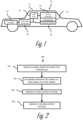
- Fig. 1 illustrates an electrical power supply device, e.g., a Universal Serial Bus (USB) power delivery (PD) device, hereinafter referred to as the PD device 10 that is designed for use in a motor vehicle 12.
- the PD device 10 may be used to support battery charging of USB enabled devices in the vehicle 12 (not shown).
- the PD device 10 includes a boost-buck DC-DC power convertor, hereinafter referred to as the DC convertor 14, that receives an input voltage from a vehicle's electrical system.
- the PD device 10 may be a buck only DC-DC power convertor.
- the output voltage can by one of at least two different voltages, a higher voltage, e.g., a 20 volt output to support a fast USB charge rate, or a lower voltage, e.g., a 5 volt output to support a normal USB charge rate.
- a higher voltage e.g., a 20 volt output to support a fast USB charge rate
- a lower voltage e.g., a 5 volt output to support a normal USB charge rate.
- the PD device 10 also includes a device controller 16 that is in communication with the DC convertor 14.
- the device controller 16 has one or more processors and memory.
- the processors may be a microprocessors, application specific integrated circuits (ASIC), or built from discrete logic and timing circuits (not shown).
- Software instructions that program the processors may be stored in a non-volatile (NV) memory device (not shown).
- the NV memory device may be contained within the microprocessor or ASIC or it may be a separate device.
- Non-limiting examples of the types of NV memory that may be used include electrically erasable programmable read only memory (EEPROM), masked read only memory (ROM), and flash memory.
- the PD device 10 also includes interface circuitry 18, such as a USB transceiver to allow the PD device 10 to establish electrical communication with other devices within the vehicle 12.
- interface circuitry 18, such as a USB transceiver to allow the PD device 10 to establish electrical communication with other devices within the vehicle 12.
- the memory further includes instructions which cause the device controller 16 to command the DC convertor 14 to output the higher output voltage in accordance with the device controller 16 receiving a run signal from the start-stop controller 20.
- the reception of the stop signal causes the device controller 16 to command the DC convertor 14 to output the lower output voltage in accordance with the device controller 16 receiving a stop signal from the start-stop controller 20.
- the run signal indicates that the IC engine 22 is running, therefore the input voltage will remain equal to or greater than the threshold voltage.
- the stop signal indicates that the IC engine 22 is not running and that the input voltage may drop to less than the threshold voltage, e.g., during a cranking transient.
- the PD device 10 is disposed within a USB port that is in communication with a USB hub 24 that is in communication with the start-stop controller 20.
- the memory includes instructions which cause the device controller 16 to command the DC convertor 14 to output the higher output voltage in accordance with the device controller 16 receiving a first USB signal from the USB hub 24 indicating that the USB hub 24 has received a run signal from the start-stop controller 20.
- the memory also includes instructions which cause the device controller 16 to command the DC convertor 14 to output the lower output voltage in accordance with the device controller 16 receiving a second USB signal from the USB hub 24 indicating that the USB hub 24 has received a stop signal from the start-stop controller 20.
- Fig. 2 illustrates a method 100 of operating the PD device 10 having the DC convertor 14 and the device controller 16 and in communication with the start-stop controller 20.
- the method 100 includes the following steps:
- the PD device 10 has negotiated a PD contract with a consumer device (not shown) at 100 watts i.e. the output voltage is 20 volts and current capacity is 5 amperes and a start-stop event occurs, in the vehicle 12, i.e. the start-stop controller 20 sends a stop signal, the PD device 10 will change the power negotiation from 100 watts to 15 watts, i.e. output voltage is 5 volts and current capacity is 3 amperes, thereby reducing power required to be supplied to the PD device 10 by the vehicle 12 and reducing the current drawn by the PD device 10 and staying within the limits of the circuits current protection devices. Per the USB PD specifications, the consumer device will select the new 15 watt capability. After the stop-start event ends, i.e., the start-stop controller 20 sends a run signal, the PD device 10 will renegotiate 100 watt capability and the consumer device will choose highest power needed.
- an electrical power supply device e.g., a USB PD device 10, and a method 100 of operating such a device.
- the device provides the benefit of a USB PD device 10 that is capable of uninterrupted supply of power from the PD device 10 to a consumer USB device during a start-stop event in a vehicle 12.
- This USB PD device 10 may also provide the benefit of reducing or "shedding" electrical load from the vehicle's electrical system by reducing, but not discontinuing, the power supplied to the USB consumer device, e.g., reducing power supplied from 100 watts to 15 watts, which allows the start-stop controller 20 to enter the start/stop mode.
- 'one or more' includes a function being performed by one element, a function being performed by more than one element, e.g., in a distributed fashion, several functions being performed by one element, several functions being performed by several elements, or any combination of the above.
- first, second, etc. are, in some instances, used herein to describe various elements, these elements should not be limited by these terms. These terms are only used to distinguish one element from another.
- a first contact could be termed a second contact, and, similarly, a second contact could be termed a first contact, without departing from the scope of the various described embodiments.
- the first contact and the second contact are both contacts, but they are not the same contact.
- the term “if' is, optionally, construed to mean “when” or “upon” or “in response to determining” or “in response to detecting,” depending on the context.
- the phrase “if it is determined” or “if [a stated condition or event] is detected” is, optionally, construed to mean “upon determining” or “in response to determining” or “upon detecting [the stated condition or event]” or “in response to detecting [the stated condition or event],” depending on the context.
Landscapes
- Engineering & Computer Science (AREA)
- Mechanical Engineering (AREA)
- Automation & Control Theory (AREA)
- Physics & Mathematics (AREA)
- General Physics & Mathematics (AREA)
- Power Engineering (AREA)
- Charge And Discharge Circuits For Batteries Or The Like (AREA)
- Direct Current Feeding And Distribution (AREA)
- Electric Propulsion And Braking For Vehicles (AREA)
- Dc-Dc Converters (AREA)
Description
- The invention generally relates to an electrical power supply device and a method of operating the electrical power supply device.
-
Publication DE 10 2004 023620 A1 discloses an energy management device for a hybrid vehicle, comprising an electro-machine connected to the vehicle electrical system via a power converter, and a battery connected to the electro-machine. The battery has a higher nominal voltage than the vehicle electrical system. The output voltage of the power converter is regulated depending on the vehicle speed and the current consumption of the vehicle electrical system. PublicationJP 3 892528 B2 JP 2016 213965 A - The present invention will now be described, by way of example with reference to the accompanying drawings, in which:
-
Fig. 1 is a schematic diagram of an electrical power supply device, according to one embodiment; and -
Fig. 2 is a flow chart of a method of operating the electrical power supply device ofFig. 1 , according to one embodiment. - Reference will now be made in detail to embodiments, examples of which are illustrated in the accompanying drawings. In the following detailed description, numerous specific details are set forth in order to provide a thorough understanding of the various described embodiments. However, it will be apparent to one of ordinary skill in the art that the various described embodiments may be practiced without these specific details. In other instances, well-known methods, procedures, components, circuits, and networks have not been described in detail so as not to unnecessarily obscure aspects of the embodiments.
- The Universal Serial Bus (USB) has evolved from a data interface capable of supplying limited power to a primary provider of power with a data interface. Today many devices charge or get their power from USB ports contained in laptops, cars, aircraft or even wall sockets. USB has become a ubiquitous power socket for many consumer devices such as cellular telephones, digital media players and/or other handheld devices. Users utilize USB to fulfil their requirements not only in terms of data but also to provide power to, or charge, their devices simply, often without the need to load a driver, in order to carry out "traditional" USB functions.
- The USB Power Delivery (PD) Specification enables the maximum functionality of USB by providing more flexible power delivery, e.g., for battery charging, along with data over a single cable. Its aim is to operate with and build on the existing USB ecosystem. The USB Power Delivery Specification 3.0 is published by the USB Implementer's Forum, Inc..
- In order to meet stringent fuel economy and emission standards, automotive original equipment manufacturers (OEMs) have included start-stop technology in their vehicles that automatically shuts down and restarts the internal combustion engine to reduce the amount of time the engine spends idling, thereby reducing fuel consumption and emissions of the vehicle.
- OEMs have imposed requirements for a USB PD device powered by the vehicle battery requires it to continue to supply power to the consumer USB device during "Start/Stop" transients in which the vehicle battery voltage temporarily dips down to as low as 6 volts to simulate the vehicle cranking during a warm start. During this transient, the USB PD device is expected to continue to function with no disruption to the consumer experience. Supplying a consistent power level during the transient will cause the current input to the PD device to rise to levels that may exceed current limits of the wiring, connectors, and/or circuit protection devices, e.g., fuses, circuit breakers, of the PD device that would cause a disruption of the consumer experience, e.g., opening a fuse and thereby causing a shutdown of the PD device.
- Some original equipment vehicle manufacturers (OEMs) monitor the power being supplied by the vehicle's electrical power system and inhibit the start-stop controller if the power supplied exceeds a power threshold.
- A proposed innovative solution is to provide a signal from the vehicle to the USB PD device to indicate the power state of the vehicle. During the normal vehicle run mode the vehicle voltage is expected to be typically in the 12-14 volt range and a buck-boost DC-DC converter can generate a higher voltage output that has a greater voltage than the vehicle voltage that can be used by the consumer charging device in a "fast charge" mode. When the vehicle enters or intends to enter the stop/start mode, i.e. the vehicle has stopped moving and automatically turns off the engine, the change in mode is communicated by a signal from the vehicle to a controller in the USB PD device and the USB PD device then renegotiates the charging contact with the consumer device to provide a lower output voltage for "normal" charging operation. When the car subsequently experiences a crank cycle transient, the buck converter is able to maintain the lower output voltage without exceeding current limits and without interrupting the charging session. After the engine starts and returns to the run mode, the USB PD device is again notified via another signal and returns to the higher voltage output.
-
Fig. 1 illustrates an electrical power supply device, e.g., a Universal Serial Bus (USB) power delivery (PD) device, hereinafter referred to as thePD device 10 that is designed for use in amotor vehicle 12. ThePD device 10 may be used to support battery charging of USB enabled devices in the vehicle 12 (not shown). ThePD device 10 includes a boost-buck DC-DC power convertor, hereinafter referred to as theDC convertor 14, that receives an input voltage from a vehicle's electrical system. ThePD device 10 may be a buck only DC-DC power convertor. The output voltage can by one of at least two different voltages, a higher voltage, e.g., a 20 volt output to support a fast USB charge rate, or a lower voltage, e.g., a 5 volt output to support a normal USB charge rate. - The
PD device 10 also includes adevice controller 16 that is in communication with theDC convertor 14. Thedevice controller 16 has one or more processors and memory. The processors may be a microprocessors, application specific integrated circuits (ASIC), or built from discrete logic and timing circuits (not shown). Software instructions that program the processors may be stored in a non-volatile (NV) memory device (not shown). The NV memory device may be contained within the microprocessor or ASIC or it may be a separate device. Non-limiting examples of the types of NV memory that may be used include electrically erasable programmable read only memory (EEPROM), masked read only memory (ROM), and flash memory. - The
PD device 10 also includesinterface circuitry 18, such as a USB transceiver to allow thePD device 10 to establish electrical communication with other devices within thevehicle 12. - The memory further includes instructions which cause the
device controller 16 to command theDC convertor 14 to output the higher output voltage in accordance with thedevice controller 16 receiving a run signal from the start-stop controller 20. The reception of the stop signal causes thedevice controller 16 to command theDC convertor 14 to output the lower output voltage in accordance with thedevice controller 16 receiving a stop signal from the start-stop controller 20. The run signal indicates that theIC engine 22 is running, therefore the input voltage will remain equal to or greater than the threshold voltage. The stop signal indicates that theIC engine 22 is not running and that the input voltage may drop to less than the threshold voltage, e.g., during a cranking transient. - The
PD device 10 is disposed within a USB port that is in communication with aUSB hub 24 that is in communication with the start-stop controller 20. The memory includes instructions which cause thedevice controller 16 to command theDC convertor 14 to output the higher output voltage in accordance with thedevice controller 16 receiving a first USB signal from theUSB hub 24 indicating that theUSB hub 24 has received a run signal from the start-stop controller 20. The memory also includes instructions which cause thedevice controller 16 to command theDC convertor 14 to output the lower output voltage in accordance with thedevice controller 16 receiving a second USB signal from theUSB hub 24 indicating that theUSB hub 24 has received a stop signal from the start-stop controller 20. -
Fig. 2 illustrates amethod 100 of operating thePD device 10 having theDC convertor 14 and thedevice controller 16 and in communication with the start-stop controller 20. Themethod 100 includes the following steps: -
STEP 102, RECEIVE A SIGNAL FROM THE START-STOP CONTROLLER, includes thePD device 10 receiving a signal from the start-stop controller 20; -
STEP 104, DETERMINE WHETHER THE SIGNAL IS A RUN SIGNAL OR A STOP SIGNAL, includes thedevice controller 16 determining whether the signal is a run signal or a stop signal; -
STEP 106, PRODUCE A FIRST OUTPUT VOLTAGE, includes thePD device 10 producing the higher output voltage via theDC convertor 14 in accordance with thedevice controller 16 determining that the signal is the run signal; and -
STEP 108, PRODUCE A SECOND OUTPUT VOLTAGE, includes thePD device 10 producing a second output voltage via theDC convertor 14 which is less than the first output voltage in accordance with thedevice controller 16 determining that that the signal is the stop signal. - If the
PD device 10 has negotiated a PD contract with a consumer device (not shown) at 100 watts i.e. the output voltage is 20 volts and current capacity is 5 amperes and a start-stop event occurs, in thevehicle 12, i.e. the start-stop controller 20 sends a stop signal, thePD device 10 will change the power negotiation from 100 watts to 15 watts, i.e. output voltage is 5 volts and current capacity is 3 amperes, thereby reducing power required to be supplied to thePD device 10 by thevehicle 12 and reducing the current drawn by thePD device 10 and staying within the limits of the circuits current protection devices. Per the USB PD specifications, the consumer device will select the new 15 watt capability. After the stop-start event ends, i.e., the start-stop controller 20 sends a run signal, thePD device 10 will renegotiate 100 watt capability and the consumer device will choose highest power needed. - Accordingly, an electrical power supply device, e.g., a
USB PD device 10, and amethod 100 of operating such a device is provided. The device provides the benefit of aUSB PD device 10 that is capable of uninterrupted supply of power from thePD device 10 to a consumer USB device during a start-stop event in avehicle 12. ThisUSB PD device 10 may also provide the benefit of reducing or "shedding" electrical load from the vehicle's electrical system by reducing, but not discontinuing, the power supplied to the USB consumer device, e.g., reducing power supplied from 100 watts to 15 watts, which allows the start-stop controller 20 to enter the start/stop mode. - While this invention has been described in terms of the preferred embodiments thereof, it is not intended to be so limited, but rather only to the extent set forth in the claims that follow. For example, the above-described embodiments (and/or aspects thereof) may be used in combination with each other. In addition, many modifications may be made to configure a particular situation or material to the teachings of the invention without departing from its scope. Dimensions, types of materials, orientations of the various components, and the number and positions of the various components described herein are intended to define parameters of certain embodiments, and are by no means limiting and are merely prototypical embodiments.
- Many other embodiments and modifications within the spirit and scope of the claims will be apparent to those of skill in the art upon reviewing the above description. The scope of the invention should, therefore, be determined with reference to the following claims, along with the full scope of equivalents to which such claims are entitled.
- As used herein, 'one or more' includes a function being performed by one element, a function being performed by more than one element, e.g., in a distributed fashion, several functions being performed by one element, several functions being performed by several elements, or any combination of the above.
- It will also be understood that, although the terms first, second, etc. are, in some instances, used herein to describe various elements, these elements should not be limited by these terms. These terms are only used to distinguish one element from another. For example, a first contact could be termed a second contact, and, similarly, a second contact could be termed a first contact, without departing from the scope of the various described embodiments. The first contact and the second contact are both contacts, but they are not the same contact.
- The terminology used in the description of the various described embodiments herein is for the purpose of describing particular embodiments only and is not intended to be limiting. As used in the description of the various described embodiments and the appended claims, the singular forms "a", "an" and "the" are intended to include the plural forms as well, unless the context clearly indicates otherwise. It will also be understood that the term "and/or" as used herein refers to and encompasses any and all possible combinations of one or more of the associated listed items. It will be further understood that the terms "includes," "including," "comprises," and/or "comprising," when used in this specification, specify the presence of stated features, integers, steps, operations, elements, and/or components, but do not preclude the presence or addition of one or more other features, integers, steps, operations, elements, components, and/or groups thereof.
- As used herein, the term "if' is, optionally, construed to mean "when" or "upon" or "in response to determining" or "in response to detecting," depending on the context. Similarly, the phrase "if it is determined" or "if [a stated condition or event] is detected" is, optionally, construed to mean "upon determining" or "in response to determining" or "upon detecting [the stated condition or event]" or "in response to detecting [the stated condition or event]," depending on the context.
- Additionally, while terms of ordinance or orientation may be used herein these elements should not be limited by these terms. All terms of ordinance or orientation, unless stated otherwise, are used for purposes distinguishing one element from another, and do not denote any particular order, order of operations, direction or orientation unless stated otherwise.
Claims (4)
- An electrical power supply device (10) configured to interface with a start-stop controller (20) of an internal combustion engine within a vehicle (12), comprising:a DC-DC power convertor configured to receive an input voltage from a vehicle battery and produce a first output voltage or a second output voltage that is less than the first output voltage provided to a consumer USB device; anda device controller (16) in communication with the DC-DC power convertor and the start-stop controller (20), said device controller (16) having one or more processors and memory, characterized in that the memory includes instructions which cause the device controller (16) to command the DC-DC power convertor to output the first output voltage in accordance with the device controller (16) receiving a run signal from the start-stop controller (20) indicating that the internal combustion engine is running and wherein the memory further includes instructions which cause the device controller (16) to command the DC-DC power convertor to output the second output voltage in accordance with the device controller (16) receiving a stop signal from the start-stop controller (20), indicating that the internal combustion engine is not running, wherein the electrical power supply device (10) is disposed within a universal serial bus, USB, port in communication with a USB hub (24) which is in communication with the start-stop controller (20), wherein the memory further includes instructions which cause the device controller (16) to command the DC-DC power convertor to output the first output voltage in accordance with the device controller (16) receiving a first USB signal from the USB hub (24) indicating that the start-stop controller (20) has transmitted the run signal, and wherein the memory additionally includes instructions which cause the device controller (16) to command the DC-DC power convertor to output the second output voltage in accordance with the device controller (16) receiving a second signal from the USB hub (24) indicating that the start-stop controller (20) has transmitted the stop signal.
- The electrical power supply device (10) according to claim 1, wherein a maximum value of the first output voltage is about 20 volts and a minimum value of the second output voltage is about 3.2 volts.
- A method (100) of operating an electrical power supply device (10) disposed within a universal serial bus (USB) port in communication with a USB hub (24) which is in communication with the start-stop controller (20) within a vehicle (12), wherein the electrical power supply device comprises a DC-DC power convertor which receives an input voltage from a vehicle battery and produces a first output voltage or a second output voltage that is less than the first output voltage provided to a consumer USB device, and a device controller (16) in communication with the DC-DC power convertor and the start-stop controller (20), said device controller (16) having one or more processors and memory, said method (100) comprising the step of:receiving a signal from the USB hub (24);determining, via the device controller (16), whether said signal is a first USB signal from the USB hub (24) indicating that the start-stop controller (20) has transmitted the run signal indicating that the internal combustion engine is running or a second signal from the USB hub (24) indicating that the start-stop controller (20) has transmitted the stop signal indicating that the internal combustion engine is not running;producing a first output voltage via the DC-DC power convertor in accordance with the device controller (16) receiving the first USB signal from the USB hub (24); andproducing a second output voltage via the DC-DC power convertor which is less than the first output voltage in accordance with the device controller (16) receiving the second USB signal from the USB hub (24).
- The method (100) according to claim 3, wherein a maximum value of the first output voltage is about 20 volts and a minimum value of the second output voltage is about 3.2 volts.
Priority Applications (1)
| Application Number | Priority Date | Filing Date | Title |
|---|---|---|---|
| EP24158126.3A EP4344960A3 (en) | 2018-04-17 | 2019-04-09 | Electrical power supply device and method of operating same |
Applications Claiming Priority (2)
| Application Number | Priority Date | Filing Date | Title |
|---|---|---|---|
| US15/954,851 US10635150B2 (en) | 2018-04-17 | 2018-04-17 | Electrical power supply device and method of operating same |
| US16/006,463 US10752189B2 (en) | 2018-04-17 | 2018-06-12 | Electrical power supply device and method of operating same |
Related Child Applications (2)
| Application Number | Title | Priority Date | Filing Date |
|---|---|---|---|
| EP24158126.3A Division-Into EP4344960A3 (en) | 2018-04-17 | 2019-04-09 | Electrical power supply device and method of operating same |
| EP24158126.3A Division EP4344960A3 (en) | 2018-04-17 | 2019-04-09 | Electrical power supply device and method of operating same |
Publications (2)
| Publication Number | Publication Date |
|---|---|
| EP3557724A1 EP3557724A1 (en) | 2019-10-23 |
| EP3557724B1 true EP3557724B1 (en) | 2024-08-07 |
Family
ID=66102968
Family Applications (2)
| Application Number | Title | Priority Date | Filing Date |
|---|---|---|---|
| EP19168163.4A Active EP3557724B1 (en) | 2018-04-17 | 2019-04-09 | Electrical power supply device and method of operating same |
| EP24158126.3A Pending EP4344960A3 (en) | 2018-04-17 | 2019-04-09 | Electrical power supply device and method of operating same |
Family Applications After (1)
| Application Number | Title | Priority Date | Filing Date |
|---|---|---|---|
| EP24158126.3A Pending EP4344960A3 (en) | 2018-04-17 | 2019-04-09 | Electrical power supply device and method of operating same |
Country Status (4)
| Country | Link |
|---|---|
| US (1) | US10752189B2 (en) |
| EP (2) | EP3557724B1 (en) |
| JP (1) | JP6750064B2 (en) |
| CN (1) | CN110386090B (en) |
Families Citing this family (5)
| Publication number | Priority date | Publication date | Assignee | Title |
|---|---|---|---|---|
| DE102021114455A1 (en) * | 2020-06-05 | 2021-12-09 | Casco Products Corporation | Power supply |
| JP7179129B1 (en) * | 2021-07-09 | 2022-11-28 | 日本航空電子工業株式会社 | Power supply control method and power supply device |
| JP2024000774A (en) * | 2022-06-21 | 2024-01-09 | アルプスアルパイン株式会社 | power distribution equipment |
| CN118232697A (en) | 2022-12-21 | 2024-06-21 | 安波福电气系统有限公司 | Isolated bidirectional DC conversion circuit and control method thereof |
| JP7670750B2 (en) * | 2023-05-15 | 2025-04-30 | 日本航空電子工業株式会社 | Power supply unit and mobile unit |
Citations (1)
| Publication number | Priority date | Publication date | Assignee | Title |
|---|---|---|---|---|
| JP2016213965A (en) * | 2015-05-08 | 2016-12-15 | オムロンオートモーティブエレクトロニクス株式会社 | Power supply device |
Family Cites Families (12)
| Publication number | Priority date | Publication date | Assignee | Title |
|---|---|---|---|---|
| JP3892528B2 (en) | 1997-05-19 | 2007-03-14 | 日産自動車株式会社 | Auxiliary power supply battery charge control device for hybrid electric vehicle |
| DE102004023620B4 (en) * | 2004-05-10 | 2018-01-04 | Volkswagen Ag | Method and device for energy management in a motor vehicle |
| JP2007137299A (en) * | 2005-11-21 | 2007-06-07 | Toyota Motor Corp | Power supply control device |
| US7644217B2 (en) * | 2007-03-02 | 2010-01-05 | Microchip Technology Incorporated | Detecting connection to a USB host or hub without using an extra status input |
| US8304929B2 (en) * | 2009-06-18 | 2012-11-06 | Lear Corporation | Inverter with network interface |
| JP6111536B2 (en) * | 2012-06-01 | 2017-04-12 | マツダ株式会社 | Vehicle power supply control method and apparatus |
| US20150258946A1 (en) * | 2014-03-13 | 2015-09-17 | GM Global Technology Operations LLC | Split-rail vehicle power architecture |
| EP3043442B1 (en) | 2015-01-12 | 2024-12-04 | SIMPower Technology Inc. | Hub having complex power converters |
| US9912243B2 (en) * | 2015-06-01 | 2018-03-06 | Microchip Technology Incorporated | Reducing power in a power converter when in a standby mode |
| JP6570416B2 (en) * | 2015-10-22 | 2019-09-04 | アルパイン株式会社 | Power supply control device and power supply control method |
| JP6777849B2 (en) * | 2016-07-13 | 2020-10-28 | ミツミ電機株式会社 | Charging control circuit for in-vehicle charging connector, in-vehicle charging connector, and in-vehicle data transfer / charging system to external devices |
| JP6719332B2 (en) | 2016-08-24 | 2020-07-08 | Fdk株式会社 | Charger |
-
2018
- 2018-06-12 US US16/006,463 patent/US10752189B2/en active Active
-
2019
- 2019-04-09 EP EP19168163.4A patent/EP3557724B1/en active Active
- 2019-04-09 EP EP24158126.3A patent/EP4344960A3/en active Pending
- 2019-04-15 JP JP2019076875A patent/JP6750064B2/en active Active
- 2019-04-15 CN CN201910298626.8A patent/CN110386090B/en active Active
Patent Citations (1)
| Publication number | Priority date | Publication date | Assignee | Title |
|---|---|---|---|---|
| JP2016213965A (en) * | 2015-05-08 | 2016-12-15 | オムロンオートモーティブエレクトロニクス株式会社 | Power supply device |
Also Published As
| Publication number | Publication date |
|---|---|
| JP6750064B2 (en) | 2020-09-02 |
| CN110386090A (en) | 2019-10-29 |
| JP2019198218A (en) | 2019-11-14 |
| US10752189B2 (en) | 2020-08-25 |
| EP3557724A1 (en) | 2019-10-23 |
| US20190315296A1 (en) | 2019-10-17 |
| EP4344960A3 (en) | 2024-07-31 |
| CN110386090B (en) | 2023-01-03 |
| EP4344960A2 (en) | 2024-04-03 |
Similar Documents
| Publication | Publication Date | Title |
|---|---|---|
| EP3557724B1 (en) | Electrical power supply device and method of operating same | |
| EP3557723B1 (en) | Electrical power supply device and method of operating same | |
| US20150336523A1 (en) | Vehicle power supply apparatus and vehicle power regeneration system | |
| US20180115178A1 (en) | Battery management system and method of controlling the same | |
| EP2272722A2 (en) | Power source apparatus for vehicle | |
| CN107218166B (en) | Load-based engine start-stop control | |
| JP5846073B2 (en) | Power system | |
| US20100244556A1 (en) | Onboard Power Supply and Method for Operating an Onboard Power Supply | |
| CN113103870A (en) | Prioritization of electric vehicle power distribution | |
| JP6642496B2 (en) | Power supply and power supply system | |
| CN104662285B (en) | Vehicle Grid Architecture | |
| CN106981914A (en) | A kind of vehicle-mounted energy control method and system based on double cell | |
| US20170274785A1 (en) | Vehicle and control method for vehicle | |
| US11342705B2 (en) | Electrical power supply device and method of operating same | |
| JP5704747B2 (en) | Charge control unit | |
| US11652315B2 (en) | Electrical power supply device | |
| WO2014025064A1 (en) | Power system for a vehicle | |
| JP2018046635A (en) | Switch control device, power supply unit and power supply system | |
| KR20150116843A (en) | Method for operating an energy supply unit for an on-board power system of a motorvehicle | |
| EP3557718B1 (en) | Electrical power supply device and method of operating same | |
| CN108352719A (en) | Supply unit | |
| JP6936683B2 (en) | Vehicle power supply system and vehicle power supply system control device | |
| CN116118652A (en) | Battery system and battery energy management method |
Legal Events
| Date | Code | Title | Description |
|---|---|---|---|
| PUAI | Public reference made under article 153(3) epc to a published international application that has entered the european phase |
Free format text: ORIGINAL CODE: 0009012 |
|
| STAA | Information on the status of an ep patent application or granted ep patent |
Free format text: STATUS: THE APPLICATION HAS BEEN PUBLISHED |
|
| AK | Designated contracting states |
Kind code of ref document: A1 Designated state(s): AL AT BE BG CH CY CZ DE DK EE ES FI FR GB GR HR HU IE IS IT LI LT LU LV MC MK MT NL NO PL PT RO RS SE SI SK SM TR |
|
| AX | Request for extension of the european patent |
Extension state: BA ME |
|
| STAA | Information on the status of an ep patent application or granted ep patent |
Free format text: STATUS: REQUEST FOR EXAMINATION WAS MADE |
|
| 17P | Request for examination filed |
Effective date: 20200404 |
|
| RBV | Designated contracting states (corrected) |
Designated state(s): AL AT BE BG CH CY CZ DE DK EE ES FI FR GB GR HR HU IE IS IT LI LT LU LV MC MK MT NL NO PL PT RO RS SE SI SK SM TR |
|
| STAA | Information on the status of an ep patent application or granted ep patent |
Free format text: STATUS: EXAMINATION IS IN PROGRESS |
|
| 17Q | First examination report despatched |
Effective date: 20211215 |
|
| RAP3 | Party data changed (applicant data changed or rights of an application transferred) |
Owner name: APTIV TECHNOLOGIES LIMITED |
|
| GRAP | Despatch of communication of intention to grant a patent |
Free format text: ORIGINAL CODE: EPIDOSNIGR1 |
|
| STAA | Information on the status of an ep patent application or granted ep patent |
Free format text: STATUS: GRANT OF PATENT IS INTENDED |
|
| RIC1 | Information provided on ipc code assigned before grant |
Ipc: H02J 7/00 20060101ALN20231223BHEP Ipc: B60R 16/03 20060101ALI20231223BHEP Ipc: H02J 7/14 20060101AFI20231223BHEP |
|
| INTG | Intention to grant announced |
Effective date: 20240118 |
|
| RIC1 | Information provided on ipc code assigned before grant |
Ipc: H02J 7/00 20060101ALN20240110BHEP Ipc: B60R 16/03 20060101ALI20240110BHEP Ipc: H02J 7/14 20060101AFI20240110BHEP |
|
| P01 | Opt-out of the competence of the unified patent court (upc) registered |
Effective date: 20240131 |
|
| GRAS | Grant fee paid |
Free format text: ORIGINAL CODE: EPIDOSNIGR3 |
|
| RAP1 | Party data changed (applicant data changed or rights of an application transferred) |
Owner name: APTIV TECHNOLOGIES AG |
|
| GRAA | (expected) grant |
Free format text: ORIGINAL CODE: 0009210 |
|
| STAA | Information on the status of an ep patent application or granted ep patent |
Free format text: STATUS: THE PATENT HAS BEEN GRANTED |
|
| AK | Designated contracting states |
Kind code of ref document: B1 Designated state(s): AL AT BE BG CH CY CZ DE DK EE ES FI FR GB GR HR HU IE IS IT LI LT LU LV MC MK MT NL NO PL PT RO RS SE SI SK SM TR |
|
| REG | Reference to a national code |
Ref country code: GB Ref legal event code: FG4D |
|
| REG | Reference to a national code |
Ref country code: CH Ref legal event code: EP |
|
| REG | Reference to a national code |
Ref country code: IE Ref legal event code: FG4D |
|
| REG | Reference to a national code |
Ref country code: DE Ref legal event code: R096 Ref document number: 602019056437 Country of ref document: DE |
|
| RAP4 | Party data changed (patent owner data changed or rights of a patent transferred) |
Owner name: APTIV TECHNOLOGIES AG |
|
| REG | Reference to a national code |
Ref country code: LT Ref legal event code: MG9D |
|
| REG | Reference to a national code |
Ref country code: NL Ref legal event code: MP Effective date: 20240807 |
|
| PG25 | Lapsed in a contracting state [announced via postgrant information from national office to epo] |
Ref country code: NO Free format text: LAPSE BECAUSE OF FAILURE TO SUBMIT A TRANSLATION OF THE DESCRIPTION OR TO PAY THE FEE WITHIN THE PRESCRIBED TIME-LIMIT Effective date: 20241107 |
|
| REG | Reference to a national code |
Ref country code: AT Ref legal event code: MK05 Ref document number: 1712014 Country of ref document: AT Kind code of ref document: T Effective date: 20240807 |
|
| PG25 | Lapsed in a contracting state [announced via postgrant information from national office to epo] |
Ref country code: PT Free format text: LAPSE BECAUSE OF FAILURE TO SUBMIT A TRANSLATION OF THE DESCRIPTION OR TO PAY THE FEE WITHIN THE PRESCRIBED TIME-LIMIT Effective date: 20241209 Ref country code: NL Free format text: LAPSE BECAUSE OF FAILURE TO SUBMIT A TRANSLATION OF THE DESCRIPTION OR TO PAY THE FEE WITHIN THE PRESCRIBED TIME-LIMIT Effective date: 20240807 Ref country code: FI Free format text: LAPSE BECAUSE OF FAILURE TO SUBMIT A TRANSLATION OF THE DESCRIPTION OR TO PAY THE FEE WITHIN THE PRESCRIBED TIME-LIMIT Effective date: 20240807 Ref country code: GR Free format text: LAPSE BECAUSE OF FAILURE TO SUBMIT A TRANSLATION OF THE DESCRIPTION OR TO PAY THE FEE WITHIN THE PRESCRIBED TIME-LIMIT Effective date: 20241108 Ref country code: PL Free format text: LAPSE BECAUSE OF FAILURE TO SUBMIT A TRANSLATION OF THE DESCRIPTION OR TO PAY THE FEE WITHIN THE PRESCRIBED TIME-LIMIT Effective date: 20240807 |
|
| PG25 | Lapsed in a contracting state [announced via postgrant information from national office to epo] |
Ref country code: BG Free format text: LAPSE BECAUSE OF FAILURE TO SUBMIT A TRANSLATION OF THE DESCRIPTION OR TO PAY THE FEE WITHIN THE PRESCRIBED TIME-LIMIT Effective date: 20240807 |
|
| PG25 | Lapsed in a contracting state [announced via postgrant information from national office to epo] |
Ref country code: LV Free format text: LAPSE BECAUSE OF FAILURE TO SUBMIT A TRANSLATION OF THE DESCRIPTION OR TO PAY THE FEE WITHIN THE PRESCRIBED TIME-LIMIT Effective date: 20240807 |
|
| PG25 | Lapsed in a contracting state [announced via postgrant information from national office to epo] |
Ref country code: AT Free format text: LAPSE BECAUSE OF FAILURE TO SUBMIT A TRANSLATION OF THE DESCRIPTION OR TO PAY THE FEE WITHIN THE PRESCRIBED TIME-LIMIT Effective date: 20240807 Ref country code: IS Free format text: LAPSE BECAUSE OF FAILURE TO SUBMIT A TRANSLATION OF THE DESCRIPTION OR TO PAY THE FEE WITHIN THE PRESCRIBED TIME-LIMIT Effective date: 20241207 |
|
| PG25 | Lapsed in a contracting state [announced via postgrant information from national office to epo] |
Ref country code: HR Free format text: LAPSE BECAUSE OF FAILURE TO SUBMIT A TRANSLATION OF THE DESCRIPTION OR TO PAY THE FEE WITHIN THE PRESCRIBED TIME-LIMIT Effective date: 20240807 |
|
| PG25 | Lapsed in a contracting state [announced via postgrant information from national office to epo] |
Ref country code: ES Free format text: LAPSE BECAUSE OF FAILURE TO SUBMIT A TRANSLATION OF THE DESCRIPTION OR TO PAY THE FEE WITHIN THE PRESCRIBED TIME-LIMIT Effective date: 20240807 Ref country code: RS Free format text: LAPSE BECAUSE OF FAILURE TO SUBMIT A TRANSLATION OF THE DESCRIPTION OR TO PAY THE FEE WITHIN THE PRESCRIBED TIME-LIMIT Effective date: 20241107 |
|
| PG25 | Lapsed in a contracting state [announced via postgrant information from national office to epo] |
Ref country code: RS Free format text: LAPSE BECAUSE OF FAILURE TO SUBMIT A TRANSLATION OF THE DESCRIPTION OR TO PAY THE FEE WITHIN THE PRESCRIBED TIME-LIMIT Effective date: 20241107 Ref country code: PT Free format text: LAPSE BECAUSE OF FAILURE TO SUBMIT A TRANSLATION OF THE DESCRIPTION OR TO PAY THE FEE WITHIN THE PRESCRIBED TIME-LIMIT Effective date: 20241209 Ref country code: PL Free format text: LAPSE BECAUSE OF FAILURE TO SUBMIT A TRANSLATION OF THE DESCRIPTION OR TO PAY THE FEE WITHIN THE PRESCRIBED TIME-LIMIT Effective date: 20240807 Ref country code: NO Free format text: LAPSE BECAUSE OF FAILURE TO SUBMIT A TRANSLATION OF THE DESCRIPTION OR TO PAY THE FEE WITHIN THE PRESCRIBED TIME-LIMIT Effective date: 20241107 Ref country code: NL Free format text: LAPSE BECAUSE OF FAILURE TO SUBMIT A TRANSLATION OF THE DESCRIPTION OR TO PAY THE FEE WITHIN THE PRESCRIBED TIME-LIMIT Effective date: 20240807 Ref country code: LV Free format text: LAPSE BECAUSE OF FAILURE TO SUBMIT A TRANSLATION OF THE DESCRIPTION OR TO PAY THE FEE WITHIN THE PRESCRIBED TIME-LIMIT Effective date: 20240807 Ref country code: IS Free format text: LAPSE BECAUSE OF FAILURE TO SUBMIT A TRANSLATION OF THE DESCRIPTION OR TO PAY THE FEE WITHIN THE PRESCRIBED TIME-LIMIT Effective date: 20241207 Ref country code: HR Free format text: LAPSE BECAUSE OF FAILURE TO SUBMIT A TRANSLATION OF THE DESCRIPTION OR TO PAY THE FEE WITHIN THE PRESCRIBED TIME-LIMIT Effective date: 20240807 Ref country code: GR Free format text: LAPSE BECAUSE OF FAILURE TO SUBMIT A TRANSLATION OF THE DESCRIPTION OR TO PAY THE FEE WITHIN THE PRESCRIBED TIME-LIMIT Effective date: 20241108 Ref country code: FI Free format text: LAPSE BECAUSE OF FAILURE TO SUBMIT A TRANSLATION OF THE DESCRIPTION OR TO PAY THE FEE WITHIN THE PRESCRIBED TIME-LIMIT Effective date: 20240807 Ref country code: ES Free format text: LAPSE BECAUSE OF FAILURE TO SUBMIT A TRANSLATION OF THE DESCRIPTION OR TO PAY THE FEE WITHIN THE PRESCRIBED TIME-LIMIT Effective date: 20240807 Ref country code: BG Free format text: LAPSE BECAUSE OF FAILURE TO SUBMIT A TRANSLATION OF THE DESCRIPTION OR TO PAY THE FEE WITHIN THE PRESCRIBED TIME-LIMIT Effective date: 20240807 Ref country code: AT Free format text: LAPSE BECAUSE OF FAILURE TO SUBMIT A TRANSLATION OF THE DESCRIPTION OR TO PAY THE FEE WITHIN THE PRESCRIBED TIME-LIMIT Effective date: 20240807 |
|
| PG25 | Lapsed in a contracting state [announced via postgrant information from national office to epo] |
Ref country code: DK Free format text: LAPSE BECAUSE OF FAILURE TO SUBMIT A TRANSLATION OF THE DESCRIPTION OR TO PAY THE FEE WITHIN THE PRESCRIBED TIME-LIMIT Effective date: 20240807 Ref country code: SM Free format text: LAPSE BECAUSE OF FAILURE TO SUBMIT A TRANSLATION OF THE DESCRIPTION OR TO PAY THE FEE WITHIN THE PRESCRIBED TIME-LIMIT Effective date: 20240807 Ref country code: RO Free format text: LAPSE BECAUSE OF FAILURE TO SUBMIT A TRANSLATION OF THE DESCRIPTION OR TO PAY THE FEE WITHIN THE PRESCRIBED TIME-LIMIT Effective date: 20240807 |
|
| PG25 | Lapsed in a contracting state [announced via postgrant information from national office to epo] |
Ref country code: EE Free format text: LAPSE BECAUSE OF FAILURE TO SUBMIT A TRANSLATION OF THE DESCRIPTION OR TO PAY THE FEE WITHIN THE PRESCRIBED TIME-LIMIT Effective date: 20240807 |
|
| PG25 | Lapsed in a contracting state [announced via postgrant information from national office to epo] |
Ref country code: CZ Free format text: LAPSE BECAUSE OF FAILURE TO SUBMIT A TRANSLATION OF THE DESCRIPTION OR TO PAY THE FEE WITHIN THE PRESCRIBED TIME-LIMIT Effective date: 20240807 |
|
| PG25 | Lapsed in a contracting state [announced via postgrant information from national office to epo] |
Ref country code: SK Free format text: LAPSE BECAUSE OF FAILURE TO SUBMIT A TRANSLATION OF THE DESCRIPTION OR TO PAY THE FEE WITHIN THE PRESCRIBED TIME-LIMIT Effective date: 20240807 |
|
| REG | Reference to a national code |
Ref country code: DE Ref legal event code: R097 Ref document number: 602019056437 Country of ref document: DE |
|
| PLBE | No opposition filed within time limit |
Free format text: ORIGINAL CODE: 0009261 |
|
| STAA | Information on the status of an ep patent application or granted ep patent |
Free format text: STATUS: NO OPPOSITION FILED WITHIN TIME LIMIT |
|
| PGFP | Annual fee paid to national office [announced via postgrant information from national office to epo] |
Ref country code: DE Payment date: 20250313 Year of fee payment: 7 |
|
| 26N | No opposition filed |
Effective date: 20250508 |
|
| PG25 | Lapsed in a contracting state [announced via postgrant information from national office to epo] |
Ref country code: SE Free format text: LAPSE BECAUSE OF FAILURE TO SUBMIT A TRANSLATION OF THE DESCRIPTION OR TO PAY THE FEE WITHIN THE PRESCRIBED TIME-LIMIT Effective date: 20240807 |
|
| REG | Reference to a national code |
Ref country code: CH Ref legal event code: H13 Free format text: ST27 STATUS EVENT CODE: U-0-0-H10-H13 (AS PROVIDED BY THE NATIONAL OFFICE) Effective date: 20251125 |
|
| PG25 | Lapsed in a contracting state [announced via postgrant information from national office to epo] |
Ref country code: LU Free format text: LAPSE BECAUSE OF NON-PAYMENT OF DUE FEES Effective date: 20250409 |
|
| PG25 | Lapsed in a contracting state [announced via postgrant information from national office to epo] |
Ref country code: MC Free format text: LAPSE BECAUSE OF FAILURE TO SUBMIT A TRANSLATION OF THE DESCRIPTION OR TO PAY THE FEE WITHIN THE PRESCRIBED TIME-LIMIT Effective date: 20240807 |
|
| REG | Reference to a national code |
Ref country code: BE Ref legal event code: MM Effective date: 20250430 |
|
| PG25 | Lapsed in a contracting state [announced via postgrant information from national office to epo] |
Ref country code: BE Free format text: LAPSE BECAUSE OF NON-PAYMENT OF DUE FEES Effective date: 20250430 |
|
| PG25 | Lapsed in a contracting state [announced via postgrant information from national office to epo] |
Ref country code: CH Free format text: LAPSE BECAUSE OF NON-PAYMENT OF DUE FEES Effective date: 20250430 |
|
| PG25 | Lapsed in a contracting state [announced via postgrant information from national office to epo] |
Ref country code: IT Free format text: LAPSE BECAUSE OF FAILURE TO SUBMIT A TRANSLATION OF THE DESCRIPTION OR TO PAY THE FEE WITHIN THE PRESCRIBED TIME-LIMIT Effective date: 20240807 |
|
| PGFP | Annual fee paid to national office [announced via postgrant information from national office to epo] |
Ref country code: GB Payment date: 20260305 Year of fee payment: 8 |
|
| PG25 | Lapsed in a contracting state [announced via postgrant information from national office to epo] |
Ref country code: IE Free format text: LAPSE BECAUSE OF NON-PAYMENT OF DUE FEES Effective date: 20250409 |
|
| PGFP | Annual fee paid to national office [announced via postgrant information from national office to epo] |
Ref country code: FR Payment date: 20260303 Year of fee payment: 8 |