EP4367652B1 - Videokamera mit ausrichtungsfunktion - Google Patents
Videokamera mit ausrichtungsfunktion Download PDFInfo
- Publication number
- EP4367652B1 EP4367652B1 EP22748537.2A EP22748537A EP4367652B1 EP 4367652 B1 EP4367652 B1 EP 4367652B1 EP 22748537 A EP22748537 A EP 22748537A EP 4367652 B1 EP4367652 B1 EP 4367652B1
- Authority
- EP
- European Patent Office
- Prior art keywords
- housing portion
- video camera
- camera
- circular
- housing
- Prior art date
- Legal status (The legal status is an assumption and is not a legal conclusion. Google has not performed a legal analysis and makes no representation as to the accuracy of the status listed.)
- Active
Links
Images





Classifications
-
- G—PHYSICS
- G08—SIGNALLING
- G08B—SIGNALLING SYSTEMS, e.g. PERSONAL CALLING SYSTEMS; ORDER TELEGRAPHS; ALARM SYSTEMS
- G08B13/00—Burglar, theft or intruder alarms
- G08B13/18—Actuation by interference with heat, light, or radiation of shorter wavelength; Actuation by intruding sources of heat, light, or radiation of shorter wavelength
- G08B13/189—Actuation by interference with heat, light, or radiation of shorter wavelength; Actuation by intruding sources of heat, light, or radiation of shorter wavelength using passive radiation detection systems
- G08B13/194—Actuation by interference with heat, light, or radiation of shorter wavelength; Actuation by intruding sources of heat, light, or radiation of shorter wavelength using passive radiation detection systems using image scanning and comparing systems
- G08B13/196—Actuation by interference with heat, light, or radiation of shorter wavelength; Actuation by intruding sources of heat, light, or radiation of shorter wavelength using passive radiation detection systems using image scanning and comparing systems using television cameras
- G08B13/19617—Surveillance camera constructional details
- G08B13/19619—Details of casing
-
- G—PHYSICS
- G03—PHOTOGRAPHY; CINEMATOGRAPHY; ANALOGOUS TECHNIQUES USING WAVES OTHER THAN OPTICAL WAVES; ELECTROGRAPHY; HOLOGRAPHY
- G03B—APPARATUS OR ARRANGEMENTS FOR TAKING PHOTOGRAPHS OR FOR PROJECTING OR VIEWING THEM; APPARATUS OR ARRANGEMENTS EMPLOYING ANALOGOUS TECHNIQUES USING WAVES OTHER THAN OPTICAL WAVES; ACCESSORIES THEREFOR
- G03B11/00—Filters or other obturators specially adapted for photographic purposes
- G03B11/04—Hoods or caps for eliminating unwanted light from lenses, viewfinders or focusing aids
-
- G—PHYSICS
- G03—PHOTOGRAPHY; CINEMATOGRAPHY; ANALOGOUS TECHNIQUES USING WAVES OTHER THAN OPTICAL WAVES; ELECTROGRAPHY; HOLOGRAPHY
- G03B—APPARATUS OR ARRANGEMENTS FOR TAKING PHOTOGRAPHS OR FOR PROJECTING OR VIEWING THEM; APPARATUS OR ARRANGEMENTS EMPLOYING ANALOGOUS TECHNIQUES USING WAVES OTHER THAN OPTICAL WAVES; ACCESSORIES THEREFOR
- G03B17/00—Details of cameras or camera bodies; Accessories therefor
- G03B17/02—Bodies
-
- H—ELECTRICITY
- H04—ELECTRIC COMMUNICATION TECHNIQUE
- H04N—PICTORIAL COMMUNICATION, e.g. TELEVISION
- H04N23/00—Cameras or camera modules comprising electronic image sensors; Control thereof
- H04N23/50—Constructional details
- H04N23/51—Housings
-
- H—ELECTRICITY
- H04—ELECTRIC COMMUNICATION TECHNIQUE
- H04N—PICTORIAL COMMUNICATION, e.g. TELEVISION
- H04N23/00—Cameras or camera modules comprising electronic image sensors; Control thereof
- H04N23/50—Constructional details
- H04N23/54—Mounting of pick-up tubes, electronic image sensors, deviation or focusing coils
-
- H—ELECTRICITY
- H04—ELECTRIC COMMUNICATION TECHNIQUE
- H04N—PICTORIAL COMMUNICATION, e.g. TELEVISION
- H04N7/00—Television systems
- H04N7/18—Closed-circuit television [CCTV] systems, i.e. systems in which the video signal is not broadcast
-
- H—ELECTRICITY
- H04—ELECTRIC COMMUNICATION TECHNIQUE
- H04N—PICTORIAL COMMUNICATION, e.g. TELEVISION
- H04N7/00—Television systems
- H04N7/18—Closed-circuit television [CCTV] systems, i.e. systems in which the video signal is not broadcast
- H04N7/183—Closed-circuit television [CCTV] systems, i.e. systems in which the video signal is not broadcast for receiving images from a single remote source
Definitions
- the present invention relates generally to video cameras and more particularly to a housing for improved assembly of a video camera.
- Video cameras may be used in for both security and surveillance.
- Security cameras also known as closed-circuit television (CCTV) cameras, are used to convey signals from one particular place to a monitor situated at a distance, whereas surveillance cameras normally work on internet protocol (IP) networks which link the camera from a remote area to an assigned security location.
- IP internet protocol
- the video camera often has an exposed camera dome which, over time, may become subjected to a variety of environmental conditions. The camera dome may become scratched or otherwise damaged and need to be replaced. Accordingly, a video camera that facilitates the ability to replace the camera dome is highly desirable.
- US2013342982 discloses a security system including modular ring housing.
- a modular building system arrangement includes a plurality of electrical building systems. Each electrical building system has a housing with a mechanical connector that is connectable with a like connector of each other building system housing. Members of any subset of the building system housings are connectable with each other to form a building system assembly.
- the building systems of the building system assembly conjointly define an electrically conductive pathway interconnecting each of the building systems of the building system assembly. The pathway carries power and/or data.
- the embodiments reside primarily in an improved housing configuration for a video camera which facilitates assembly at the factory level, facilitates installation at the customer level, and facilitates replacement of a camera dome. Accordingly, the components have been represented where appropriate by conventional symbols in the drawings, showing only those specific details that are pertinent to understanding the embodiments of the present invention so as not to obscure the disclosure with details that will be readily apparent to those of ordinary skill in the art having the benefit of the description herein.
- a video camera comprising a housing configured to provide improved assembly both at the manufacturing level and the installation level.
- the video camera may a security camera, also known as a CCTV camera, or the video camera may be a surveillance camera, which works on an internet protocol (IP) network which links the camera from a remote area to an assigned security location.
- IP internet protocol
- the housing configuration further advantageously facilitates the removal and replacement of the camera dome.
- FIG. 1 is an isometric view 100 of a housing 102 for a video camera formed in accordance with some embodiments.
- the video camera housing 102 provides a plurality of housing portions for camera and IR electronics.
- the plurality of housing portions comprises a top housing portion 104, a mid-housing portion 106 and a bottom housing portion 108.
- the top housing portion 104, the mid-housing portion 106 and the bottom housing portion 108 may also be referred to as first, second, and third housing portions respectively.
- the top housing portion 104 is configured as a circular and rounded exterior contoured wall 110, the circular and rounded exterior contoured wall has an exterior recessed feature 112 formed along an edge 114.
- the top housing portion 104 may comprise a second opposing recessed feature 112' which will be shown in other views.
- the mid-housing portion 106 is formed of an infrared (IR) window ring 116 having an alignment tab 118 extending therefrom.
- the mid-housing portion 106 may comprise a second opposed alignment tab 118', which will be shown in other views.
- the alignment tab 118 is aligned and recessed within the exterior recessed feature 112 of the circular and rounded exterior contoured wall 110 of the top housing portion 104.
- the IR window ring 116 is formed of a material permeable to IR and opaque to visible light.
- the bottom housing portion 108 comprises a camera dome 120 seated within and protruding from the IR window ring 116.
- the top housing portion 104 is highly contrasted to the mid-housing portion 106 and bottom housing portion 108. Exterior recessed feature 112 with alignment tab 118 recessed therein provide a natural finger recess with affordance to facilitate gripping during assembly, during installation, and during removal and replacement of the camera dome 120.
- the dark contrast of the combined mid and bottom housing portions 106, 108 further beneficially protects the top housing portion 104 from getting dirty during handling.
- the video camera of the various embodiments may also be referred to as a fisheye camera as it advantageously provides 360° panoramic views of large areas from a single vantage point.
- the fisheye camera provides superior situational awareness with no blind spots for a cost-effective solution, along with multiple mounting and accessory options for easy installation.
- the video camera may be one of an internet protocol (IP) camera or a closed circuit television (CCTV) camera.
- IP internet protocol
- CCTV closed circuit television
- IP internet protocol
- IP wide-angle panoramic internet protocol
- IP internet protocol
- the IP camera is a type of digital video camera that receives control data and sends image data via an IP network.
- the IP camera may be used, for example, for surveillance but unlike analog closed-circuit television cameras, the IP camera requires no local recording device, only a local area network.
- the video camera provided by the various embodiments advantageously provides an improved housing configuration that allows for ease of manufacturability, ease of installation, and improved ease of replacement of the dome camera.
- the video camera housing further includes an offset parting line 122 which is formed between the top housing portion 104 and the mid-housing portion 106.
- the offset parting line 122 helps to further recess and protect the printed branding insignia 124 on alignment tab 118.
- the parting line does not compromise water test specifications, such as IP66, IP67, and NEMA 4x hosedown.
- NEMA stands for National Electric Manufacturers Association which sets test specifications for gasket enclosure type products intended for indoor or outdoor use primarily to provide a degree of protection against windblown dust and rain, splashing water, and hose directed water; undamaged by ice which forms on the enclosure.
- the alignment tab 118 forms a three-sided frame around a branding insignia 124 printed thereon.
- the three-sided frame provides improved prominence to the branding insignia 124.
- the IR window edge 114 with the offset parting line 122 running along the three-sided frame enhances protection to the recessed alignment tab 118 and branding insignia 124 printed thereon.
- the housing 102 may be mounted to, and dismounted from, a circular mounting apparatus having video camera electronics (shown in other views), wherein the circular mounting apparatus is attached to a wall or ceiling.
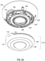
- FIG. 2A is a partially assembled isometric view of the video camera formed in accordance with some embodiments.
- This view shows the mid-housing portion 106 and bottom housing portion 108 coupled together as a sub-assembly 210 for mounting to the top housing portion 104.
- the sub-assembly 210 couples IR window ring 116 and camera dome 120, and then the sub-assembly 210 is coupled to the top housing portion 104.
- the IR window ring 116 is formed of a material permeable to IR and opaque to visible light.
- the IR window ring 116 further comprises the alignment tab 118 extending therefrom for aligning with the exterior recessed feature 112 of the top housing portion 104.
- the alignment tab118 frames the branding insignia 124 printed on an exterior surface of the alignment tab.
- the alignment tab 118 can frame a trademark or other wording or symbols to facilitate product recognition as well as facilitate assembly and disassembly.
- the top housing portion 104 includes IR electronics, such as IR circuitry 202 and IR lenslets 204, surrounding a pass-through opening 206 (for a camera lens located on the circular mounting apparatus - shown in other views).
- the lenslets 204 are positioned so as to align with the IR window ring 116.
- a sealing ring 208 provides sealing between the top housing portion 104 and the sub-assembly 210 formed of the mid and bottom housing portions 106, 108.
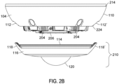
- FIG. 2B is a partially assembled side view of the video camera formed in accordance with some embodiments.
- This view shows two alignment tabs 118, 118' extending from the IR window ring 116 for aligning and coupling within two exterior recessed features 112, 112' formed along the edge 114 of the top housing portion 104.
- the recessed features 112, 112' provide improved assembly, installation and ruggedness that protects against damage to the tabs 118, 118' during drop impact.
- the top housing portion 104 with recessed features 112, 112' is made of a plastic suitable for protection against 20 joules on impact (IK10 rating), making it extremely safe & vandal proof.
- the camera dome 120 of the bottom housing portion 108 is mounted within the IR window ring 116.
- the sub-assembly 210 of the two housing portions 106, 108 is thus able to align and fit to the top housing portion 104.
- This view shows the lenslets 204 of top housing portion 104 extending outward so as to align within the IR window ring 116.
- FIG. 2B further shows the first housing portion 104 being formed of a rounded exterior contoured wall 110 formed between a first larger circular opening 214 and a second smaller sized circular opening 224.
- FIG. 2C is a partial cutaway view of the assembled housing 102 showing a seal ring 208, seated over a projected flange 216 of the second housing portion 106, and retained within a rail 212 of the first housing portion 104.
- the seal 208 has a top seal plateau surface 208a with two side seal surfaces 208 b, 208c extending downward therefrom, so as to cover the flange 216.
- the seal ring 208 is held in place via the rail 212.
- the seal ring 208, flange 216 and rail 212 advantageously provide a circular seal between the top housing portion 104 and IR window ring 116. The sealing improves ruggedization and minimizes water intrusion.
- FIG. 2C further emphasizes the protection provided to alignment tab 118 by the exterior recessed feature 112 formed along an edge 114 of top housing portion 104.
- the recessed alignment tab 118 frames and protects the branding insignia 124 printed thereon.
- the IR window ring 116 with edge 114 forming the offset parting line 122 further provide enhanced protection to the recessed alignment tab 118 and branding insignia 124 printed thereon.
- FIGs. 2A , 2B and 2C show an advantageous tray shape of the IR window ring 116 formed of sloped side walls where the alignment tabs 118, 118' can be easily gripped like tray handles.
- the entire sub-assembly 210 formed of the combined mid and bottom housing portions can fit in the palm of a hand, so that the alignments tabs 118, 118' can be aligned into the respective recessed features 112, 112' of the top housing portion 104.
- Exterior recessed features 112, 112' provide a natural finger recess with affordance for ease of assembly of housing 102.
- the lenslets 204 which protrude out from the top housing portion 104, align within and face the sloped sidewalls of the IR window ring 116.
- the exterior recessed features 112, 112' further facilitate installation of housing 102 to a ceiling mounted apparatus (shown in other views) by allowing installers to use the recessed features 112, 112' with alignment tabs 118, 118' recessed therein as grip locations which protect the top housing portion 104 from getting dirty during installation.
- FIG. 3 is an exploded view 300 of the video camera formed in accordance with some embodiments.
- View 300 shows the top housing portion 104 having exterior recessed feature 112 integrated thereon, as well as IR circuitry 202 and IR lenslets 204 protruding therefrom.
- View 300 shows the mid-housing portion 106 formed of IR window ring 116 in its individual piece part form.
- View 300 further shows the bottom housing portion 108 having camaera dome 120 in its piece part form.
- a first plurality of screws 302, or other coupling means may be used to mount the IR window ring 116 to the bottom housing portion 108 having camera dome 120.
- a second plurality of screws 304, or other coupling means may be used to mount the top housing portion 104 to the combined sub-assembly of mid and bottom housing portions 106, 108
- the IR window ring 116 is formed of a material permeable to IR and opaque to visible light.
- the IR window ring 116 provides alignment tab 118 extending therefrom for aligning with the exterior recessed feature 112 of the top housing portion 104.
- the alignment tab 118 frames the branding insignia 124 printed thereon.
- IR lenslets 204 become seated within the IR window ring 116.
- a first plurality of screws 302, or other coupling means may be used to mount the IR window ring 116 to the bottom housing portion 108 having camera dome 120.
- a second plurality of screws 304, or other coupling means may be used to mount the top housing portion 104 to the combined sub-assembly of mid and bottom housing portions 106, 108.
- the bottom housing portion 108 comprises the camera dome 120 surrounded by, and protruding from, an opaque circular base 308 of the bottom housing portion.
- the bottom housing portion 108 is coupled, via the opaque circular base 308, to the mid-housing portion 106 within a corresponding opening 306 of the mid housing portion 106.
- the opening 306 of the mid-housing portion 106 is surrounded by a flat, planar circular surface 316 of the mid-housing portion.
- FIG. 4 is another exploded view 400 of the video camera housing with a circular mounting apparatus 402 in accordance with some embodiments.
- the circular mounting apparatus 402 includes video camera electronics and is mountable to a surface, such as a ceiling, wall or other suitable surface.
- the housing 102 is formed of top housing portion 104, mid-housing portion 106, and bottom housing portion 108. Screws 302 couple the mid-housing portion 106 to the bottom housing portion 108 forming sub-assembly 210. Top housing portion 104 is then coupled to sub-assembly 210 via screws 304. This forms the housing assembly which can be shipped to an installer.
- the video camera electronics of the circular mounting apparatus 402 include a camera lens 408 extending therefrom.
- the camera lens 408 protrudes through the pass-through opening 206 of top housing 104 and aligns within the camera dome 120 of the bottom housing portion 108.
- FIG. 5 is another view 500 of the video camera housing 102 and circular mounting apparatus 402 in accordance with some embodiments.
- View 500 is provided to show the advantageous manner in which the assembled housing 102 can be mounted and dismounted from the circular mounting apparatus 402 via screws 502 within the top housing portion 104 and corresponding screw inserts 504 in the circular mounting apparatus 402.
- the sub-assembly 210 FIG. 2B
- the bottom housing portion 108 having camera dome 120 can be removed from the mid-housing portion 106 having IR window ring 116.
- the camera dome 120 can be easily replaced by providing a replacement bottom housing portion with new dome.
- the replacement bottom housing portion with new dome can be attached to the mid-housing portion 106, thereby forming a new sub-assembly.
- the new subassembly is re-attached to the top housing portion 104.
- the entire housing 102 (with new camera dome) is then re-attached to circular mounting apparatus 402 through screws 502 and screw inserts 504.
- a video camera comprising: a circular mounting apparatus 402 containing video camera electronics 410, and a housing 102 coupled to the mounting apparatus.
- the housing 102 is formed of three housing portions comprising a first top housing portion 104, a second mid-housing portion 106, and a third bottom housing portion 108.
- the first housing portion 104 contains IR electronics 202, and the first housing portion is formed of the rounded exterior contoured wall 110 formed between the first circular opening 214 for coupling to the circular mounting apparatus 402 and the second smaller sized circular opening 224 through which the plurality of IR lenslets 204 surrounding the pass-through opening 206 protrude.
- the rounded exterior contoured wall 110 has at least one exterior recessed feature 112 formed therein along the edge 114 of the second smaller sized circular opening 224.
- the second housing portion 106 provides the IR window ring 116 having the alignment tab 118 extending therefrom.
- the alignment tab 118 may frame a printed branding insignia 124 disposed thereon.
- the alignment tab 118 being recessed within exterior recessed feature 112 of the first housing portion provides additional framing and protection to the branding insignia printed thereon.
- the IR window ring 116 is formed of the material permeable to IR and opaque to visible light.
- the alignment tab 118 is aligned and recessed within the exterior recessed feature 112 of the rounded exterior contoured wall 110 of the first housing portion 104.
- the rounded exterior contoured wall 110 of the first housing portion 104 is formed of material that blocks light
- the IR window ring 116 of the second housing portion is formed of material that is permeable to IR light.
- the top housing portion 104 may be formed, for example, of an aluminum casting
- the mid-housing portion 106 may be formed, for example, of a light transmissible polycarbonate.
- the third housing portion 108 is formed of the opaque circular base 308 having translucent camera dome 120 protruding therefrom.
- the opaque circular base 308 is seated within the IR window ring 116 thereby aligning the translucent camera dome 120 with the pass-through opening 206 of the first housing portion 104.
- the third housing portion 108 may be formed of an opaque polycarbonate ring surrounding the dome 120 which may be formed of a translucent polycarbonate suitable for optical applications.
- the opaque circular base 308 of the third housing portion 108 provides a seal preventing light from passing between the camera pass-through 206 and the IR window ring 116.
- the offset parting line 122 is formed between the first housing portion 104 and the second housing portion 106 to provide extra recessed protection to the alignment tabs 118, 118' and printed branding insignia 124. Hence, the alignment tabs 118, 118' and branding insignia 124 disposed thereon are well protecting against drop impact.
- the bottom housing portion 108 with camera dome 120 is replaceable.
- the video camera housing 102 may be mounted to the circular mounting apparatus 402 having the video camera electronics.
- the video camera may be a closed circuit television (CCTV) camera or an internet protocol (IP) camera.
- the housing 102 provided by the various embodiments, advantageously facilitates assembly at the factory level, facilitates installation at in the field, and facilitates replacement of the camera dome.
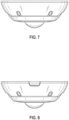
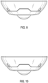
- FIGs. 6-12 show design views of the video camera housing 102 in accordance with some embodiments.
- FIG. 6 is an isometric view of the video camera housing formed in accordance with some embodiments.
- FIG. 7 is a first side view of the video camera housing formed in accordance with some embodiments.
- FIG. 8 is a second side view of the video camera housing formed in accordance with some embodiments.
- FIG. 9 is a third side view of the video camera housing formed in accordance with some embodiments.
- FIG. 10 is a fourth side view of the video camera housing formed in accordance with some embodiments.
- FIG. 11 is a top view of the video camera housing formed in accordance with some embodiments.
- FIG. 12 is a bottom view of the video camera housing formed in accordance with some embodiments.
Landscapes
- Engineering & Computer Science (AREA)
- Multimedia (AREA)
- Signal Processing (AREA)
- Physics & Mathematics (AREA)
- General Physics & Mathematics (AREA)
- Studio Devices (AREA)
Claims (8)
- Videokamera, die Folgendes umfasst:eine kreisförmige Montageeinrichtung (402), die eine Videokameraelektronik enthält;ein Gehäuse (102), das mit der kreisförmigen Montageeinrichtung (402) gekoppelt ist, wobei das Gehäuse (102) aus drei Gehäuseabschnitten gebildet ist, umfassend:einen ersten oberen Gehäuseabschnitt (104), der Infrarot-, IR-, Elektronik (202) enthält, wobei der erste obere Gehäuseabschnitt (104) aus einer abgerundeten Außenkonturwand (110) gebildet ist, die zwischen einer ersten kreisförmigen Öffnung (214) zum Koppeln mit der kreisförmigen Montageeinrichtung (402) und einer zweiten kreisförmigen Öffnung (224) kleinerer Größe gebildet ist, durch die mehrere IR-Linsen (204), die eine Kameradurchgangsöffnung (206) umgeben, hervorstehen, wobei die abgerundete Außenkonturwand (110) ein darin entlang einer Kante (114) der zweiten kreisförmigen Öffnung (224) kleinerer Größe gebildetes äußeres Vertiefungsmerkmal (112) aufweist;einen zweiten mittleren Gehäuseabschnitt (106), der einen IR-Fensterring (116) mit einer sich davon erstreckenden Ausrichtungslasche (118) bereitstellt, wobei der IR-Fensterring (116) aus einem Material gebildet ist, das für IR durchlässig und für sichtbares Licht opak ist, und wobei die Ausrichtungslasche (118) innerhalb des äußeren Vertiefungsmerkmals (112) der abgerundeten Außenkonturwand (110) des ersten oberen Gehäuseabschnitts (104) ausgerichtet und vertieft ist; undeinen dritten unteren Gehäuseabschnitt (108), der eine Kamerakuppel (120) bereitstellt, die aus einem opaken kreisförmigen Ring (308) mit einer davon hervorstehenden transluzenten Kamerakuppel (120) gebildet ist, wobei der opake kreisförmige Ring (308) innerhalb des IR-Fensterrings (116) sitzt, wodurch die transluzente Kamerakuppel (120) mit der Durchgangsöffnung (206) des ersten oberen Gehäuseabschnitts (104) ausgerichtet wird.
- Videokamera nach Anspruch 1, wobei der opake kreisförmige Ring (308) eine Dichtung bereitstellt, die verhindert, dass Licht zwischen der Durchgangsöffnung (206) und dem IR-Fensterring (116) hindurchtritt.
- Videokamera nach Anspruch 1, die ferner Folgendes umfasst:
eine versetzte Trennlinie (122), die zwischen dem ersten oberen Gehäuseabschnitt (104) und dem zweiten mittleren Gehäuseabschnitt (106) gebildet ist. - Videokamera nach Anspruch 1, wobei der dritte untere Gehäuseabschnitt (108) mit der Kamerakuppel (120) austauschbar ist.
- Videokamera nach Anspruch 1, wobei die abgerundete Außenkonturwand (110) des ersten oberen Gehäuseabschnitts (104) aus einem Material gebildet ist, das Licht blockiert, und der IR-Fensterring (116) des zweiten mittleren Gehäuseabschnitts (106) aus einem Material gebildet ist, das für IR-Licht durchlässig ist.
- Videokamera nach Anspruch 1, wobei die vertiefte Ausrichtungslasche (118) einen Rahmen und Schutz für ein darauf gedrucktes Markenzeichen (124) bereitstellt.
- Videokamera nach Anspruch 1, die ferner Folgendes umfasst:
eine kreisförmige Montageeinrichtung (402) zur Montage des Gehäuses an einer Oberfläche. - Videokamera nach Anspruch 1, wobei die Videokamera eine einer Kamera für Fernsehen für geschlossene Nutzergruppe, CCTV, oder einer Internetprotokoll-, IP-, Kamera ist.
Applications Claiming Priority (2)
| Application Number | Priority Date | Filing Date | Title |
|---|---|---|---|
| US17/368,388 US11388317B1 (en) | 2021-07-06 | 2021-07-06 | Video camera with alignment feature |
| PCT/US2022/035415 WO2023283081A1 (en) | 2021-07-06 | 2022-06-29 | Video camera with alignment feature |
Publications (2)
| Publication Number | Publication Date |
|---|---|
| EP4367652A1 EP4367652A1 (de) | 2024-05-15 |
| EP4367652B1 true EP4367652B1 (de) | 2025-05-07 |
Family
ID=82323915
Family Applications (1)
| Application Number | Title | Priority Date | Filing Date |
|---|---|---|---|
| EP22748537.2A Active EP4367652B1 (de) | 2021-07-06 | 2022-06-29 | Videokamera mit ausrichtungsfunktion |
Country Status (4)
| Country | Link |
|---|---|
| US (2) | US11388317B1 (de) |
| EP (1) | EP4367652B1 (de) |
| CA (1) | CA3223761C (de) |
| WO (1) | WO2023283081A1 (de) |
Families Citing this family (4)
| Publication number | Priority date | Publication date | Assignee | Title |
|---|---|---|---|---|
| US12231751B1 (en) * | 2023-02-14 | 2025-02-18 | United States Of America, Represented By The Secretary Of The Navy | Modular omni-directional sensor array enclosure |
| USD1065294S1 (en) * | 2023-03-15 | 2025-03-04 | Hanwha Vision Co., Ltd. | Surveillance camera |
| CN120128775B (zh) * | 2023-12-08 | 2025-12-05 | 杭州海康威视数字技术股份有限公司 | 摄像机装置 |
| FR3171953A1 (fr) * | 2025-02-05 | 2026-08-07 | Legrand France | Appareil électrique comprenant une plaque de finition rotative sur un enjoliveur |
Family Cites Families (19)
| Publication number | Priority date | Publication date | Assignee | Title |
|---|---|---|---|---|
| US6729497B2 (en) * | 2001-12-28 | 2004-05-04 | Npf Limited | Paintball container |
| US6775912B2 (en) * | 2002-01-24 | 2004-08-17 | A. Richard Ltée | Blade scraping tool |
| JP4152980B2 (ja) * | 2005-10-14 | 2008-09-17 | 松下電器産業株式会社 | ドーム型カメラ |
| US8525880B2 (en) * | 2008-11-21 | 2013-09-03 | Robert Bosch Gmbh | Security system including modular ring housing |
| US8345989B1 (en) * | 2009-02-16 | 2013-01-01 | Parata Systems, Llc | Illumination station for use in pharmaceutical identification system and methods therefor |
| WO2013121880A1 (ja) * | 2012-02-14 | 2013-08-22 | 富士フイルム株式会社 | ドーム型カメラ |
| USD734380S1 (en) | 2012-10-16 | 2015-07-14 | Altia Systems Inc | Panoramic video camera chassis |
| JP6089320B2 (ja) * | 2013-04-05 | 2017-03-08 | パナソニックIpマネジメント株式会社 | カメラ装置 |
| USD768751S1 (en) | 2013-10-18 | 2016-10-11 | Altia Systems, Inc. | Camera chassis |
| EP2887328B1 (de) * | 2013-12-19 | 2016-04-20 | Axis AB | Auf einer Schiene mit vorbestimmten Befestigungspunkten montierte Überwachungsvorrichtungen |
| US20170111557A1 (en) * | 2015-10-20 | 2017-04-20 | Google Inc. | Camera assembly with filter providing different effective entrance pupil sizes based on light type |
| USD796567S1 (en) | 2016-07-15 | 2017-09-05 | Avigilon Corporation | Enclosure for a camera |
| USD815677S1 (en) | 2016-09-19 | 2018-04-17 | Coasia Microelectronics(Shanghai) Co. Ltd | 360° panoramic camera |
| EP3333816B1 (de) * | 2016-12-09 | 2018-10-03 | Axis AB | Kameraanordnung mit beleuchtung |
| GB2576459B (en) * | 2017-06-05 | 2022-03-16 | Avigilon Corp | Spherical camera |
| JP2019020557A (ja) * | 2017-07-14 | 2019-02-07 | キヤノン株式会社 | 撮像装置 |
| JP7016644B2 (ja) * | 2017-08-25 | 2022-02-07 | キヤノン株式会社 | 撮像装置 |
| EP3515153B1 (de) * | 2018-01-19 | 2020-07-29 | Axis AB | Kamera mit heizanordnung und verfahren zum erwärmen eines kamerasichtfensters |
| JP2021047448A (ja) | 2020-12-08 | 2021-03-25 | 日本電気株式会社 | 撮影システム、撮影方法及びプログラム |
-
2021
- 2021-07-06 US US17/368,388 patent/US11388317B1/en active Active
-
2022
- 2022-06-09 US US17/836,259 patent/US12160646B2/en active Active
- 2022-06-29 WO PCT/US2022/035415 patent/WO2023283081A1/en not_active Ceased
- 2022-06-29 EP EP22748537.2A patent/EP4367652B1/de active Active
- 2022-06-29 CA CA3223761A patent/CA3223761C/en active Active
Also Published As
| Publication number | Publication date |
|---|---|
| US11388317B1 (en) | 2022-07-12 |
| US20230008347A1 (en) | 2023-01-12 |
| WO2023283081A1 (en) | 2023-01-12 |
| CA3223761C (en) | 2024-04-09 |
| US12160646B2 (en) | 2024-12-03 |
| EP4367652A1 (de) | 2024-05-15 |
| CA3223761A1 (en) | 2023-01-12 |
Similar Documents
| Publication | Publication Date | Title |
|---|---|---|
| CA3223761C (en) | Video camera with alignment feature | |
| US4485407A (en) | Television camera for indoor and outdoor use | |
| US9823552B2 (en) | Lens and sensor attachment for a digital camera and related retrofit kit and retrofit method | |
| US20040048507A1 (en) | Quick-release sensor assembly and method | |
| EP2688281A2 (de) | Kameragehäuse | |
| US7835634B2 (en) | Camera enclosure sealing system and method | |
| US8487998B2 (en) | Digital peephole viewer device | |
| US20170357146A1 (en) | Support and connection unit for cameras | |
| WO2019182324A1 (ko) | 렌즈 모듈 및 카메라 모듈 | |
| CN101171728B (zh) | 用于墙式安装电气设备的支撑框架 | |
| EP1969571A2 (de) | Video türüberwachungssystem | |
| US12526498B2 (en) | Imaging apparatus with heat transfer member | |
| CN101160957A (zh) | 网络照像机安装系统 | |
| JP2010224298A (ja) | 撮像装置 | |
| KR100996471B1 (ko) | 사면 감시용 카메라 장치 | |
| KR100709561B1 (ko) | 돔카메라 | |
| JP3358233B2 (ja) | ビデオカメラ装置 | |
| CN209845082U (zh) | 摄像头模块、音箱集成件及电子设备 | |
| CN209343009U (zh) | 镜头罩、相机及可移动设备 | |
| CN210201963U (zh) | 可视对讲设备室外机及可视对讲设备 | |
| KR102721808B1 (ko) | 모듈형 서라운드 카메라 시스템 | |
| WO2004086753A1 (ja) | 撮像装置 | |
| CN222073293U (zh) | 一种摄像装置及安防设备 | |
| KR102950287B1 (ko) | 무볼트 전면구조를 접목한 멀티센서를 구비한 방폭형 카메라 | |
| KR200402677Y1 (ko) | 감시용 카메라 |
Legal Events
| Date | Code | Title | Description |
|---|---|---|---|
| STAA | Information on the status of an ep patent application or granted ep patent |
Free format text: STATUS: UNKNOWN |
|
| STAA | Information on the status of an ep patent application or granted ep patent |
Free format text: STATUS: THE INTERNATIONAL PUBLICATION HAS BEEN MADE |
|
| PUAI | Public reference made under article 153(3) epc to a published international application that has entered the european phase |
Free format text: ORIGINAL CODE: 0009012 |
|
| STAA | Information on the status of an ep patent application or granted ep patent |
Free format text: STATUS: REQUEST FOR EXAMINATION WAS MADE |
|
| 17P | Request for examination filed |
Effective date: 20240110 |
|
| AK | Designated contracting states |
Kind code of ref document: A1 Designated state(s): AL AT BE BG CH CY CZ DE DK EE ES FI FR GB GR HR HU IE IS IT LI LT LU LV MC MK MT NL NO PL PT RO RS SE SI SK SM TR |
|
| DAV | Request for validation of the european patent (deleted) | ||
| DAX | Request for extension of the european patent (deleted) | ||
| REG | Reference to a national code |
Ref country code: DE Ref country code: DE Ref legal event code: R079 Ref document number: 602022014398 Country of ref document: DE Free format text: PREVIOUS MAIN CLASS: G08B0013193000 Ipc: G08B0013196000 |
|
| GRAP | Despatch of communication of intention to grant a patent |
Free format text: ORIGINAL CODE: EPIDOSNIGR1 |
|
| STAA | Information on the status of an ep patent application or granted ep patent |
Free format text: STATUS: GRANT OF PATENT IS INTENDED |
|
| RIC1 | Information provided on ipc code assigned before grant |
Ipc: H04N 23/51 20230101ALI20250113BHEP Ipc: H04N 7/18 20060101ALI20250113BHEP Ipc: G03B 17/02 20210101ALI20250113BHEP Ipc: G08B 13/196 20060101AFI20250113BHEP |
|
| INTG | Intention to grant announced |
Effective date: 20250123 |
|
| GRAS | Grant fee paid |
Free format text: ORIGINAL CODE: EPIDOSNIGR3 |
|
| GRAA | (expected) grant |
Free format text: ORIGINAL CODE: 0009210 |
|
| STAA | Information on the status of an ep patent application or granted ep patent |
Free format text: STATUS: THE PATENT HAS BEEN GRANTED |
|
| AK | Designated contracting states |
Kind code of ref document: B1 Designated state(s): AL AT BE BG CH CY CZ DE DK EE ES FI FR GB GR HR HU IE IS IT LI LT LU LV MC MK MT NL NO PL PT RO RS SE SI SK SM TR |
|
| P01 | Opt-out of the competence of the unified patent court (upc) registered |
Free format text: CASE NUMBER: APP_16083/2025 Effective date: 20250402 |
|
| REG | Reference to a national code |
Ref country code: GB Ref legal event code: FG4D |
|
| REG | Reference to a national code |
Ref country code: CH Ref legal event code: EP |
|
| REG | Reference to a national code |
Ref country code: DE Ref legal event code: R096 Ref document number: 602022014398 Country of ref document: DE |
|
| REG | Reference to a national code |
Ref country code: IE Ref legal event code: FG4D |
|
| PGFP | Annual fee paid to national office [announced via postgrant information from national office to epo] |
Ref country code: AT Payment date: 20250721 Year of fee payment: 4 |
|
| REG | Reference to a national code |
Ref country code: NL Ref legal event code: MP Effective date: 20250507 |
|
| PG25 | Lapsed in a contracting state [announced via postgrant information from national office to epo] |
Ref country code: PT Free format text: LAPSE BECAUSE OF FAILURE TO SUBMIT A TRANSLATION OF THE DESCRIPTION OR TO PAY THE FEE WITHIN THE PRESCRIBED TIME-LIMIT Effective date: 20250908 Ref country code: ES Free format text: LAPSE BECAUSE OF FAILURE TO SUBMIT A TRANSLATION OF THE DESCRIPTION OR TO PAY THE FEE WITHIN THE PRESCRIBED TIME-LIMIT Effective date: 20250507 Ref country code: FI Free format text: LAPSE BECAUSE OF FAILURE TO SUBMIT A TRANSLATION OF THE DESCRIPTION OR TO PAY THE FEE WITHIN THE PRESCRIBED TIME-LIMIT Effective date: 20250507 |
|
| REG | Reference to a national code |
Ref country code: LT Ref legal event code: MG9D |
|
| PG25 | Lapsed in a contracting state [announced via postgrant information from national office to epo] |
Ref country code: NO Free format text: LAPSE BECAUSE OF FAILURE TO SUBMIT A TRANSLATION OF THE DESCRIPTION OR TO PAY THE FEE WITHIN THE PRESCRIBED TIME-LIMIT Effective date: 20250807 Ref country code: GR Free format text: LAPSE BECAUSE OF FAILURE TO SUBMIT A TRANSLATION OF THE DESCRIPTION OR TO PAY THE FEE WITHIN THE PRESCRIBED TIME-LIMIT Effective date: 20250808 |
|
| PG25 | Lapsed in a contracting state [announced via postgrant information from national office to epo] |
Ref country code: NL Free format text: LAPSE BECAUSE OF FAILURE TO SUBMIT A TRANSLATION OF THE DESCRIPTION OR TO PAY THE FEE WITHIN THE PRESCRIBED TIME-LIMIT Effective date: 20250507 Ref country code: PL Free format text: LAPSE BECAUSE OF FAILURE TO SUBMIT A TRANSLATION OF THE DESCRIPTION OR TO PAY THE FEE WITHIN THE PRESCRIBED TIME-LIMIT Effective date: 20250507 |
|
| REG | Reference to a national code |
Ref country code: AT Ref legal event code: MK05 Ref document number: 1793370 Country of ref document: AT Kind code of ref document: T Effective date: 20250507 |
|
| PG25 | Lapsed in a contracting state [announced via postgrant information from national office to epo] |
Ref country code: BG Free format text: LAPSE BECAUSE OF FAILURE TO SUBMIT A TRANSLATION OF THE DESCRIPTION OR TO PAY THE FEE WITHIN THE PRESCRIBED TIME-LIMIT Effective date: 20250507 |
|
| PG25 | Lapsed in a contracting state [announced via postgrant information from national office to epo] |
Ref country code: HR Free format text: LAPSE BECAUSE OF FAILURE TO SUBMIT A TRANSLATION OF THE DESCRIPTION OR TO PAY THE FEE WITHIN THE PRESCRIBED TIME-LIMIT Effective date: 20250507 Ref country code: AT Free format text: LAPSE BECAUSE OF FAILURE TO SUBMIT A TRANSLATION OF THE DESCRIPTION OR TO PAY THE FEE WITHIN THE PRESCRIBED TIME-LIMIT Effective date: 20250507 |
|
| PG25 | Lapsed in a contracting state [announced via postgrant information from national office to epo] |
Ref country code: RS Free format text: LAPSE BECAUSE OF FAILURE TO SUBMIT A TRANSLATION OF THE DESCRIPTION OR TO PAY THE FEE WITHIN THE PRESCRIBED TIME-LIMIT Effective date: 20250807 |
|
| PG25 | Lapsed in a contracting state [announced via postgrant information from national office to epo] |
Ref country code: IS Free format text: LAPSE BECAUSE OF FAILURE TO SUBMIT A TRANSLATION OF THE DESCRIPTION OR TO PAY THE FEE WITHIN THE PRESCRIBED TIME-LIMIT Effective date: 20250907 |
|
| PG25 | Lapsed in a contracting state [announced via postgrant information from national office to epo] |
Ref country code: LV Free format text: LAPSE BECAUSE OF FAILURE TO SUBMIT A TRANSLATION OF THE DESCRIPTION OR TO PAY THE FEE WITHIN THE PRESCRIBED TIME-LIMIT Effective date: 20250507 |
|
| PG25 | Lapsed in a contracting state [announced via postgrant information from national office to epo] |
Ref country code: DK Free format text: LAPSE BECAUSE OF FAILURE TO SUBMIT A TRANSLATION OF THE DESCRIPTION OR TO PAY THE FEE WITHIN THE PRESCRIBED TIME-LIMIT Effective date: 20250507 Ref country code: SM Free format text: LAPSE BECAUSE OF FAILURE TO SUBMIT A TRANSLATION OF THE DESCRIPTION OR TO PAY THE FEE WITHIN THE PRESCRIBED TIME-LIMIT Effective date: 20250507 |
|
| PG25 | Lapsed in a contracting state [announced via postgrant information from national office to epo] |
Ref country code: CZ Free format text: LAPSE BECAUSE OF FAILURE TO SUBMIT A TRANSLATION OF THE DESCRIPTION OR TO PAY THE FEE WITHIN THE PRESCRIBED TIME-LIMIT Effective date: 20250507 |
|
| PG25 | Lapsed in a contracting state [announced via postgrant information from national office to epo] |
Ref country code: EE Free format text: LAPSE BECAUSE OF FAILURE TO SUBMIT A TRANSLATION OF THE DESCRIPTION OR TO PAY THE FEE WITHIN THE PRESCRIBED TIME-LIMIT Effective date: 20250507 |
|
| PG25 | Lapsed in a contracting state [announced via postgrant information from national office to epo] |
Ref country code: SK Free format text: LAPSE BECAUSE OF FAILURE TO SUBMIT A TRANSLATION OF THE DESCRIPTION OR TO PAY THE FEE WITHIN THE PRESCRIBED TIME-LIMIT Effective date: 20250507 |
|
| REG | Reference to a national code |
Ref country code: CH Ref legal event code: H13 Free format text: ST27 STATUS EVENT CODE: U-0-0-H10-H13 (AS PROVIDED BY THE NATIONAL OFFICE) Effective date: 20260127 |
|
| PG25 | Lapsed in a contracting state [announced via postgrant information from national office to epo] |
Ref country code: IT Free format text: LAPSE BECAUSE OF FAILURE TO SUBMIT A TRANSLATION OF THE DESCRIPTION OR TO PAY THE FEE WITHIN THE PRESCRIBED TIME-LIMIT Effective date: 20250507 |
|
| REG | Reference to a national code |
Ref country code: DE Ref legal event code: R097 Ref document number: 602022014398 Country of ref document: DE |
|
| PG25 | Lapsed in a contracting state [announced via postgrant information from national office to epo] |
Ref country code: LU Free format text: LAPSE BECAUSE OF NON-PAYMENT OF DUE FEES Effective date: 20250629 |
|
| PG25 | Lapsed in a contracting state [announced via postgrant information from national office to epo] |
Ref country code: MC Free format text: LAPSE BECAUSE OF FAILURE TO SUBMIT A TRANSLATION OF THE DESCRIPTION OR TO PAY THE FEE WITHIN THE PRESCRIBED TIME-LIMIT Effective date: 20250507 |
|
| REG | Reference to a national code |
Ref country code: BE Ref legal event code: MM Effective date: 20250630 |
|
| PG25 | Lapsed in a contracting state [announced via postgrant information from national office to epo] |
Ref country code: RO Free format text: LAPSE BECAUSE OF FAILURE TO SUBMIT A TRANSLATION OF THE DESCRIPTION OR TO PAY THE FEE WITHIN THE PRESCRIBED TIME-LIMIT Effective date: 20250507 |
|
| PLBE | No opposition filed within time limit |
Free format text: ORIGINAL CODE: 0009261 |
|
| STAA | Information on the status of an ep patent application or granted ep patent |
Free format text: STATUS: NO OPPOSITION FILED WITHIN TIME LIMIT |
|
| REG | Reference to a national code |
Ref country code: CH Ref legal event code: L10 Free format text: ST27 STATUS EVENT CODE: U-0-0-L10-L00 (AS PROVIDED BY THE NATIONAL OFFICE) Effective date: 20260318 |
|
| PG25 | Lapsed in a contracting state [announced via postgrant information from national office to epo] |
Ref country code: IE Free format text: LAPSE BECAUSE OF NON-PAYMENT OF DUE FEES Effective date: 20250629 |
|
| 26N | No opposition filed |
Effective date: 20260210 |
|
| PG25 | Lapsed in a contracting state [announced via postgrant information from national office to epo] |
Ref country code: BE Free format text: LAPSE BECAUSE OF NON-PAYMENT OF DUE FEES Effective date: 20250630 |
|
| PG25 | Lapsed in a contracting state [announced via postgrant information from national office to epo] |
Ref country code: CH Free format text: LAPSE BECAUSE OF NON-PAYMENT OF DUE FEES Effective date: 20250630 |
|
| PG25 | Lapsed in a contracting state [announced via postgrant information from national office to epo] |
Ref country code: LT Free format text: LAPSE BECAUSE OF FAILURE TO SUBMIT A TRANSLATION OF THE DESCRIPTION OR TO PAY THE FEE WITHIN THE PRESCRIBED TIME-LIMIT Effective date: 20250507 |
|
| PGFP | Annual fee paid to national office [announced via postgrant information from national office to epo] |
Ref country code: GB Payment date: 20260604 Year of fee payment: 5 |
|
| PGFP | Annual fee paid to national office [announced via postgrant information from national office to epo] |
Ref country code: DE Payment date: 20260515 Year of fee payment: 5 |
|
| PGFP | Annual fee paid to national office [announced via postgrant information from national office to epo] |
Ref country code: FR Payment date: 20260605 Year of fee payment: 5 |
|
| PG25 | Lapsed in a contracting state [announced via postgrant information from national office to epo] |
Ref country code: SE Free format text: LAPSE BECAUSE OF FAILURE TO SUBMIT A TRANSLATION OF THE DESCRIPTION OR TO PAY THE FEE WITHIN THE PRESCRIBED TIME-LIMIT Effective date: 20250507 Ref country code: CY Free format text: LAPSE BECAUSE OF FAILURE TO SUBMIT A TRANSLATION OF THE DESCRIPTION OR TO PAY THE FEE WITHIN THE PRESCRIBED TIME-LIMIT Effective date: 20250507 |