EP4366126A1 - Verfahren und vorrichtung zur konfiguration mehrerer empfangsspulen in einer vorrichtung mit drahtloser stromübertragung - Google Patents
Verfahren und vorrichtung zur konfiguration mehrerer empfangsspulen in einer vorrichtung mit drahtloser stromübertragung Download PDFInfo
- Publication number
- EP4366126A1 EP4366126A1 EP22856289.8A EP22856289A EP4366126A1 EP 4366126 A1 EP4366126 A1 EP 4366126A1 EP 22856289 A EP22856289 A EP 22856289A EP 4366126 A1 EP4366126 A1 EP 4366126A1
- Authority
- EP
- European Patent Office
- Prior art keywords
- coil
- receiving coil
- receiving
- wireless power
- cooking apparatus
- Prior art date
- Legal status (The legal status is an assumption and is not a legal conclusion. Google has not performed a legal analysis and makes no representation as to the accuracy of the status listed.)
- Pending
Links
Images











Classifications
-
- H—ELECTRICITY
- H05—ELECTRIC TECHNIQUES NOT OTHERWISE PROVIDED FOR
- H05B—ELECTRIC HEATING; ELECTRIC LIGHT SOURCES NOT OTHERWISE PROVIDED FOR; CIRCUIT ARRANGEMENTS FOR ELECTRIC LIGHT SOURCES, IN GENERAL
- H05B6/00—Heating by electric, magnetic or electromagnetic fields
- H05B6/02—Induction heating
- H05B6/10—Induction heating apparatus, other than furnaces, for specific applications
- H05B6/12—Cooking devices
- H05B6/1209—Cooking devices induction cooking plates or the like and devices to be used in combination with them
- H05B6/1236—Cooking devices induction cooking plates or the like and devices to be used in combination with them adapted to induce current in a coil to supply power to a device and electrical heating devices powered in this way
-
- H—ELECTRICITY
- H02—GENERATION; CONVERSION OR DISTRIBUTION OF ELECTRIC POWER
- H02J—ELECTRIC POWER NETWORKS; CIRCUIT ARRANGEMENTS OR SYSTEMS FOR SUPPLYING OR DISTRIBUTING ELECTRIC POWER; SYSTEMS FOR STORING ELECTRIC ENERGY
- H02J50/00—Circuit arrangements or systems for wireless supply or distribution of electric power
- H02J50/005—Mechanical details of housing or structure aiming to accommodate the power transfer means, e.g. mechanical integration of coils, antennas or transducers into emitting or receiving devices
-
- H—ELECTRICITY
- H02—GENERATION; CONVERSION OR DISTRIBUTION OF ELECTRIC POWER
- H02J—ELECTRIC POWER NETWORKS; CIRCUIT ARRANGEMENTS OR SYSTEMS FOR SUPPLYING OR DISTRIBUTING ELECTRIC POWER; SYSTEMS FOR STORING ELECTRIC ENERGY
- H02J50/00—Circuit arrangements or systems for wireless supply or distribution of electric power
- H02J50/10—Circuit arrangements or systems for wireless supply or distribution of electric power using inductive coupling
- H02J50/12—Circuit arrangements or systems for wireless supply or distribution of electric power using inductive coupling of the resonant type
-
- A—HUMAN NECESSITIES
- A47—FURNITURE; DOMESTIC ARTICLES OR APPLIANCES; COFFEE MILLS; SPICE MILLS; SUCTION CLEANERS IN GENERAL
- A47J—KITCHEN EQUIPMENT; COFFEE MILLS; SPICE MILLS; APPARATUS FOR MAKING BEVERAGES
- A47J27/00—Cooking-vessels
- A47J27/21—Water-boiling vessels, e.g. kettles
- A47J27/21008—Water-boiling vessels, e.g. kettles electrically heated
- A47J27/2105—Water-boiling vessels, e.g. kettles electrically heated of the cordless type, i.e. whereby the water vessel can be plugged into an electrically-powered base element
-
- H—ELECTRICITY
- H02—GENERATION; CONVERSION OR DISTRIBUTION OF ELECTRIC POWER
- H02J—ELECTRIC POWER NETWORKS; CIRCUIT ARRANGEMENTS OR SYSTEMS FOR SUPPLYING OR DISTRIBUTING ELECTRIC POWER; SYSTEMS FOR STORING ELECTRIC ENERGY
- H02J50/00—Circuit arrangements or systems for wireless supply or distribution of electric power
-
- H—ELECTRICITY
- H02—GENERATION; CONVERSION OR DISTRIBUTION OF ELECTRIC POWER
- H02J—ELECTRIC POWER NETWORKS; CIRCUIT ARRANGEMENTS OR SYSTEMS FOR SUPPLYING OR DISTRIBUTING ELECTRIC POWER; SYSTEMS FOR STORING ELECTRIC ENERGY
- H02J50/00—Circuit arrangements or systems for wireless supply or distribution of electric power
- H02J50/10—Circuit arrangements or systems for wireless supply or distribution of electric power using inductive coupling
-
- H—ELECTRICITY
- H02—GENERATION; CONVERSION OR DISTRIBUTION OF ELECTRIC POWER
- H02J—ELECTRIC POWER NETWORKS; CIRCUIT ARRANGEMENTS OR SYSTEMS FOR SUPPLYING OR DISTRIBUTING ELECTRIC POWER; SYSTEMS FOR STORING ELECTRIC ENERGY
- H02J50/00—Circuit arrangements or systems for wireless supply or distribution of electric power
- H02J50/40—Circuit arrangements or systems for wireless supply or distribution of electric power using two or more transmitting or receiving devices
-
- H—ELECTRICITY
- H02—GENERATION; CONVERSION OR DISTRIBUTION OF ELECTRIC POWER
- H02J—ELECTRIC POWER NETWORKS; CIRCUIT ARRANGEMENTS OR SYSTEMS FOR SUPPLYING OR DISTRIBUTING ELECTRIC POWER; SYSTEMS FOR STORING ELECTRIC ENERGY
- H02J50/00—Circuit arrangements or systems for wireless supply or distribution of electric power
- H02J50/40—Circuit arrangements or systems for wireless supply or distribution of electric power using two or more transmitting or receiving devices
- H02J50/402—Circuit arrangements or systems for wireless supply or distribution of electric power using two or more transmitting or receiving devices the two or more transmitting or the two or more receiving devices being integrated in the same unit, e.g. power mats with several coils or antennas with several sub-antennas
-
- H—ELECTRICITY
- H02—GENERATION; CONVERSION OR DISTRIBUTION OF ELECTRIC POWER
- H02J—ELECTRIC POWER NETWORKS; CIRCUIT ARRANGEMENTS OR SYSTEMS FOR SUPPLYING OR DISTRIBUTING ELECTRIC POWER; SYSTEMS FOR STORING ELECTRIC ENERGY
- H02J50/00—Circuit arrangements or systems for wireless supply or distribution of electric power
- H02J50/80—Circuit arrangements or systems for wireless supply or distribution of electric power involving the exchange of data, concerning supply or distribution of electric power, between transmitting devices and receiving devices
-
- H—ELECTRICITY
- H05—ELECTRIC TECHNIQUES NOT OTHERWISE PROVIDED FOR
- H05B—ELECTRIC HEATING; ELECTRIC LIGHT SOURCES NOT OTHERWISE PROVIDED FOR; CIRCUIT ARRANGEMENTS FOR ELECTRIC LIGHT SOURCES, IN GENERAL
- H05B6/00—Heating by electric, magnetic or electromagnetic fields
- H05B6/02—Induction heating
- H05B6/10—Induction heating apparatus, other than furnaces, for specific applications
- H05B6/12—Cooking devices
-
- H—ELECTRICITY
- H05—ELECTRIC TECHNIQUES NOT OTHERWISE PROVIDED FOR
- H05B—ELECTRIC HEATING; ELECTRIC LIGHT SOURCES NOT OTHERWISE PROVIDED FOR; CIRCUIT ARRANGEMENTS FOR ELECTRIC LIGHT SOURCES, IN GENERAL
- H05B6/00—Heating by electric, magnetic or electromagnetic fields
- H05B6/02—Induction heating
- H05B6/10—Induction heating apparatus, other than furnaces, for specific applications
- H05B6/12—Cooking devices
- H05B6/1209—Cooking devices induction cooking plates or the like and devices to be used in combination with them
- H05B6/1245—Cooking devices induction cooking plates or the like and devices to be used in combination with them with special coil arrangements
- H05B6/1281—Cooking devices induction cooking plates or the like and devices to be used in combination with them with special coil arrangements with flat coils
-
- H—ELECTRICITY
- H05—ELECTRIC TECHNIQUES NOT OTHERWISE PROVIDED FOR
- H05B—ELECTRIC HEATING; ELECTRIC LIGHT SOURCES NOT OTHERWISE PROVIDED FOR; CIRCUIT ARRANGEMENTS FOR ELECTRIC LIGHT SOURCES, IN GENERAL
- H05B2213/00—Aspects relating both to resistive heating and to induction heating, covered by H05B3/00 and H05B6/00
- H05B2213/06—Cook-top or cookware capable of communicating with each other
Definitions
- Various embodiments of the disclosure relate to a method and apparatus for configuring multilayer receiving coils in a device using wireless power transmission.
- Wireless power transfer refers to a technology that removes a power line for supplying power to a home appliance or an electric vehicle, and replaces the power line wirelessly.
- the contactless induction coupling method may use a low-cost switching type power conversion element due to a relatively low frequency to provide excellent power transmission efficiency, and thus is being commercialized in a wireless shaver, a powered toothbrush, etc., and has been recently used in mobile IT devices such as mobile phones, etc.
- a WPT scheme based on the contactless induction coupling method is a scheme to transmit/receive power wirelessly by mutual linkage using a transmitting-side transmitting coil (a magnetic resonator) having a power source and a receiving-side receiving coil receiving power wirelessly.
- a transmitting-side transmitting coil a magnetic resonator
- a cooking apparatus driven by wireless power including a wireless power receiving unit configured to wirelessly receive power from a wireless power transmitting unit and a processor configured to control the wireless power receiving unit.
- the wireless power receiving unit the cooking apparatus includes a first receiving coil and a second receiving coil having a shared center with the first receiving coil whereby the second receiving coil shares at least a part of a center of the first receiving coil, the first receiving coil and the second receiving coil being arranged on different layers along a longitudinal direction of the shared center.
- a cooking apparatus driven by wireless power including a wireless power receiving unit configured to wirelessly receive power from a wireless power transmitting unit and a processor configured to control the wireless power receiving unit.
- the wireless power receiving unit of the cooking apparatus includes a receiving coil, a pickup coil configured to supply power to a control unit including the processor, and a communication coil configured to communicate with a station including the wireless power transmitting unit.
- a cooking apparatus driven by wireless power including a wireless power receiving unit configured to wirelessly receive power from a wireless power transmitting unit and a processor configured to control the wireless power receiving unit.
- the wireless power receiving unit of the cooking apparatus includes a first receiving coil and a second receiving coil that does not share a center of the first receiving coil, the first receiving coil unit and the second receiving coil unit being arranged on different layers perpendicular to a plane formed by windings of coils thereof.
- the expression "at least one of a, b or c" indicates only a, only b, only c, both a and b, both a and c, both b and c, all of a, b, and c, or variations thereof.
- unit indicates a unit for processing at least one function or operation, and may be implemented in hardware, software, or in a combination of hardware and software.
- FIG. 1 is a view for describing a wireless power-driven cooking system according to an embodiment of the disclosure.
- a cooking apparatus 1000 of a wireless power-driven cooking system 100 may mean any type of home appliance cooking apparatuses in which cooking is performed in an induction heating (IH) manner or a heating manner.
- the cooking apparatus 1000 according to the disclosure includes a cooking apparatus for 'heating', but should be understood as including any home appliance apparatus operating with wireless 'electricity' supply in addition to the cooking apparatus for 'heating'.
- a heating apparatus 2000 of FIG. 1 may form a magnetic field by causing a current to flow in a wireless power transmitting unit 2010 including a working coil (or a transmitting coil), such that an eddy current may be generated in the cooking apparatus 1000 or the magnetic field may be induced in a wireless power receiving unit 1010 including a receiving coil. Electrical output or heating (heating) may be achieved on the cooking apparatus 1000 through the induced eddy current or the magnetic field induced in the wireless power receiving unit 1010.
- the cooking apparatus 1000 shown in FIG. 1 shows an induction cooking apparatus using electromagnetic induction as an example of a cooking apparatus.
- the wireless power-driven cooking apparatus 1000 is not limited to the induction cooking apparatus. That is, the cooking apparatus 1000 according to the disclosure may include a coffee machine, a toaster, an induction heater, an electric cooker, a waffle maker, a blender, an electric kettle, a pot, a frying pan, a steamer, etc., without being limited thereto.
- the cooking apparatus 1000 may be induced and heated by the heating apparatus 2000, and may be a container in various forms having magnetic properties to communicate with the heating apparatus 2000.
- the contents in the cooking apparatus 1000 driven by wireless power may be liquid such as water, tea, coffee, soup, juice, wine, etc., or solid such as butter, meat, etc., without being limited thereto.
- the cooking apparatus 1000 may be of an induction heating (IH) type, or may be of a heater type.
- IH induction heating
- IH may refer to a method of heating a metal object using an electromagnetic induction phenomenon.
- an alternating current (AC) is supplied to the wireless power transmitting unit 2010 of the heating apparatus 2000
- a magnetic field changing temporally may be introduced in the transmitting coil included in the wireless power transmitting unit 2010.
- the magnetic field generated by the transmitting coil passes through a bottom surface of the cooking apparatus 1000.
- metal e.g., iron, steel nickel, various kinds of alloys, etc.
- Such a rotating current is referred to as an eddy current
- a phenomenon in which a current is induced by the temporally changing magnetic field is referred to as an electromagnetic induction phenomenon.
- heat may be generated on the bottom surface of the cooking apparatus 1000 due to the eddy current and a resistance of metal (e.g., iron). At this time, the contents of the cooking apparatus 1000 may be heated by the generated heat.
- the cooking apparatus of the IH type will be described in more detail with reference to FIG. 9B .
- the load may include any electrical load capable of operating a home appliance as well a heater or a motor.
- the cooking apparatus 1000 may include a heater, a motor, or a charging target battery, as an example of an internal load.
- the wireless power receiving unit 1010 may not only heat a heater that is a load or drive a motor, but also supply power to any means capable of operating with power supplied thereto.
- the heater may heat the contents in the cooking apparatus 1000.
- a shape of the heater may be various, and a material of an outer cover (e.g., iron, stainless steel, copper, aluminum, incoloy, inconel, etc.) may also be various.
- the receiving coil of the cooking apparatus 1000 may receive power from the transmitting coil included in the wireless power transmitting unit 2010 of the heating apparatus 2000 wirelessly through the magnetic induction method.
- the magnetic induction method may be a method of delivering energy by applying the magnetic field formed by the current flowing through the transmitting coil to the receiving coil.
- FIG. 1 shows a cross-section 110 of the cooking apparatus 1000 driven by wireless power and the heating apparatus 2000.
- the heating apparatus 2000 may include the wireless power transmitting unit 2010 including the transmitting coil being supplied with commercial power in a wired manner and wirelessly transmitting power.
- the cooking apparatus 1000 may include the wireless power receiving unit 1010 including a receiving coil wirelessly supplied with power by the magnetic induction method from the transmitting coil of the heating apparatus 2000.
- a load 1070 heated by the receiving coil may be included on the wireless power receiving unit 1010 of the cooking apparatus 1000.
- the load 1070 may include a heater, a motor, a battery target battery, etc.
- the heating apparatus 2000 may include glass 2020 on the wireless power transmitting unit 2010.
- the glass 2020 of the heating apparatus 2000 may include reinforced glass such as ceramic glass, etc., such that a top plate of the heating apparatus 2000 is not easily damaged.
- the heating apparatus 1000 which includes the wireless power receiving unit 1010 and the load 1070, and the heating apparatus 2000, such that the cooking apparatus 1000 may be freely separated from the heating apparatus 2000 including the wireless power transmitting unit 2010, in a cord-free state.
- the cooking apparatus 1000 may be an integral home appliance including the heating apparatus 2000.
- the cooking apparatus 1000 and the heating apparatus 2000 may be products handled separately and sold separately, and may be treated as one product.
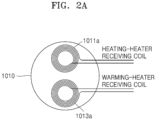
- FIG. 2A is an aerial view of a wireless power receiving unit according to an embodiment of the disclosure.
- a heating-heater receiving coil 1011a and a warming-heater receiving coil 1013a may be arranged.
- Two or more heating levels are required in the cooking apparatus 1000, such that the heating-heater receiving coil 1011a and the warming-heater receiving coil 1013a may be separately arranged.
- FIG. 2B is a cross-sectional view of a cooking system according to an embodiment of the disclosure.
- FIG. 2B is a cross-sectional view showing the cooking apparatus 1000 including the wireless power receiving unit 1010 according to FIG. 2A , together with the heating apparatus 2000.
- the cooking apparatus 1000 according to FIG. 2B may include a first receiving coil unit 1011 and a second receiving coil unit 1013 that have different heating levels while receiving wireless power from the wireless power transmitting unit 2010.
- the wireless power-driven cooking apparatus 1000 may include a first heater 1071 connected to the first receiving coil unit 1011 for a heating output and a second heater 1073 connected to the second receiving coil unit 1013 for a heating output.
- the heating output according to the first receiving coil unit 1011 and the heating output according to the second receiving coil unit 1013 may be different from each other.
- the heating output according to the first receiving coil unit 1011 and the heating output according to the second receiving coil unit 1013 may correspond to the heating-heating level of the heating-heater receiving coil 1011a and the warming-heating level of the warming-heater receiving coil 1013a shown in FIG. 2A .
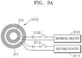
- FIG. 3A is an aerial view of a wireless power-driven cooking apparatus according to an embodiment of the disclosure.
- the wireless power receiving unit 1010 of the wireless power-driven cooking apparatus 1000 according to FIG. 3A may include a heating-heater coil 311 and a warming-heater coil 313 that may be arranged in the wireless power receiving unit 1010 while sharing a center.
- Reference to a 'Sharing a center' in the present specification may mean that centers of two or more coils are substantially shared, but may not mean that the centers do not necessarily match exactly in a mathematical and physical manner.
- the planar area of the wireless power receiving unit 1010 when the centers of the two or more coils partially intersect each other, it may be referred to as 'sharing a center'.
- the shapes of the heating-heater coil 311 and the warming-heater coil 313 may be concentric or oval, but are not be limited thereto.
- the shapes of the heating-heater coil 311 and the warming-heater coil 313 may be close to a square or rectangle, and may be rectangular with each round vertex.
- the warming-heater coil 313 may be arranged inwardly from the heating-heater coil 311 with respect to the center thereof, and the heating-heater coil 311 may be arranged outwardly from the warming-heater coil 313.
- the warming-heater coil 313 may be arranged outwardly from the heating-heater coil 311 with respect to the center thereof, and the heating-heater coil 311 may be arranged inwardly from the warming-heater coil 313.
- the heating-heater coil 311 may drive a heating heater 3111, and the warming-heater coil 313 may drive a warming heater 3131 to output different-level heating outputs.
- a scheme according to FIG. 3A is more useful than a scheme according to FIG. 2A in that the planar areas of the wireless power receiving unit 1010 and the cooking apparatus 1000 may be reduced. Nevertheless, according to the scheme of FIG. 3A , the planar area of the wireless power receiving unit 1010 needs to be increased as much as the area where the heating-heater coil 311 and the warming-heater coil 313 are wound.
- the cooking apparatus 1000 may further include switches 3112 and 3132 for turning on/off the operations of the heating heater 3111 and the warming heater 3131, for example, a relay switch or a semiconductor switch.
- switches 3112 and 3132 for turning on/off the operations of the heating heater 3111 and the warming heater 3131, for example, a relay switch or a semiconductor switch.
- the wireless power receiving unit 1010, the heating heater 3111, and the warming heater 3131 may be arranged on the same layer.
- a structure may be formed in which the wireless power receiving unit 1010, the heating heater 3111, and the warming heater 3131 are arranged on different layers, while minimizing the planar areas.
- FIG. 3B is a cross-sectional view of a wireless power-driven cooking apparatus according to an embodiment of the disclosure.
- a wireless power-driven cooking system 300 may include the cooking apparatus 1000, the heating apparatus 2000, and a control unit 3000.
- control unit 3000 may be included in the cooking apparatus 1000.
- the heating apparatus 2000 may include a wireless power transmitting unit 2010 including a transmitting coil 331 connected to a commercial power source via a wire and supplying wireless power to the cooking apparatus 1000.
- the heating apparatus 2000 may include a receiving communication coil 335 to determine whether the cooking apparatus 1000 is stationed on the heating apparatus 2000.
- the receiving communication coil 335 may be a communication coil capable of short-range communication including near field communication (NFC) sensing, Bluetooth communication, etc.
- the cooking apparatus 1000 may include the wireless power receiving unit 1010 including a transmitting communication coil 345.
- the stationing may include the meaning that docking is made such that wireless power transmission and reception may be performed between the cooking apparatus 1000 and the heating apparatus 2000.
- FIG. 4 is a cross-sectional view of a wireless power-driven cooking apparatus having a structure in which a plurality of receiving coils are stacked, according to an embodiment of the disclosure.
- a first receiving coil unit 411 and a second receiving coil unit 413 which receive power wirelessly from the wireless power transmitting unit 2010, may be arranged on different layers in a stacked structure without being on the same plane.
- the plurality of coils may be stacked on a plurality of layers.
- the receiving coils when there are three receiving coils, they may be stacked in a 3-layer manner, and when there are four receiving coils, they may be stacked in a 4-layer manner.
- the first receiving coil when the number of windings of a first receiving coil among three receiving coils is relatively large and the number of windings of a second receiving coil and a third receiving coil is relatively small, the first receiving coil may be included in one layer and the second receiving coil and the third receiving coil may be included in another layer, such that the three receiving coils may be stacked on two layers.
- the receiving coils in the case of four receiving coils, the receiving coils may be stacked in various ways, such as 2+1+1, 3+1, and 2+2, depending on the number of windings of each receiving coil. In this way, the cross-sectional area of the cooking apparatus (wireless power receiving unit) may be reduced by stacking the receiving coils on a plurality of layers.
- the two receiving coil arrangement schemes according to FIG. 2A or FIG. 3A require a relatively broader planar area than the receiving coil arrangement scheme according to FIG. 4 .
- a planar area may be relatively small even when each receiving coil has the same number of windings as the receiving coil of FIG. 2A or FIG. 3A . Therefore, the receiving coil arrangement scheme of FIG. 4 makes it possible to manufacture the cooking apparatus in a compact size.
- the first receiving coil unit 411 and the second receiving coil unit 413 when they may share the center thereof. In this case, around the first receiving coil unit 411 and the second receiving coil unit 413, coils may be wound in a circular or oval shape, without being limited thereto.
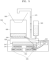
- FIG. 5 is a cross-sectional view of a wireless power-driven cooking apparatus according to an embodiment of the disclosure.
- a wireless power-driven cooking apparatus according to an embodiment of the disclosure is a coffee machine.
- a coffee machine 500 may be driven at two heating levels by two stacked receiving coils.
- a heating-heating level for heating cold water supplied from a water tank 560 is required.
- a warming-heating level for warming the coffee pot 590 is required.
- the coffee machine 500 requires at least two heating levels.
- a heating first receiving coil 541 and a warming second receiving coil 543 may be stacked on two layers.
- the heating first receiving coil 541 may be connected to a heating heater 547 and heat water.
- the warming second receiving coil 543 may be connected to the warming heater 549 to maintain the coffee in the coffee pot 590 in a warming state.
- a communication coil 545 may transmit to the station, a signal indicating that the coffee pot 590 has been stationed.
- the communication coil 545 may be arranged outwardly from the warming second receiving coil 543 while sharing the center thereof with the warming second receiving coil 543.
- the communication coil 545 for informing whether the coffee pot 590 is placed on the station may be arranged inwardly from the warming second receiving coil 543 while sharing the center thereof with the warming second receiving coil 543.
- the station may be the heating apparatus 2000.
- the communication coil 545 may be arranged on the same layer as the warming second receiving coil 543 because the number of windings of the warming second receiving coil 543 is less than that of the heating first receiving coil 541, thus occupying a smaller planar area than the heating first receiving coil 541.
- the heating first receiving coil 541 may be arranged on a lower layer, and the warming second receiving coil 543 may be arranged on an upper layer.
- FIG. 6A is a cross-sectional view of a wireless power-driven cooking apparatus including ferrite according to an embodiment of the disclosure.
- a ferrite 605 may be arranged on a top layer of two receiving coils 601 and 603.
- the ferrite 605 as a magnetic body may enhance a magnetic field according to a magnetic flux passing through the receiving coils 601 and 603.
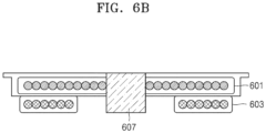
- FIG. 6B is a cross-sectional view of a wireless power-driven cooking apparatus including ferrite according to an embodiment of the disclosure.
- a ferrite 607 may be arranged in a longitudinal direction of a center shared between the two receiving coils 601 and 603.
- a structure in which the ferrite 607 is arranged in the center according to FIG. 6A may reduce a stacking thickness compared to the stacking structure according to FIG. 6A .
- FIG. 7 is a view for showing that a wireless power-driven cooking apparatus is stationed in a heating apparatus, according to an embodiment of the disclosure.
- cooking apparatuses 1000-1, 1000-2, and 1000-3 show various examples stationed on heating apparatuses 2000-1, 2000-2, and 2000-3.
- the heating apparatuses 2000-1, 2000-2, and 2000-3 may be first home appliances, and the cooking apparatuses 1000-1, 1000-2, and 1000-3 may be second home appliances separately from the heating apparatuses 2000-1, 2000-2, and 2000-3.
- the heating apparatuses 2000-1, 2000-2, and 2000-3 may be devices for transmitting wireless power or home appliances functioning as heating apparatuses.
- the cooking apparatuses 1000-1, 1000-2, and 1000-3 may be home appliances supplied with wireless power from the heating apparatuses 2000-1, 2000-2, and 2000-3 to independently use an electric power source.
- 7-1 of FIG. 7 shows a form in which the cooking apparatus 1000-1 is stationed on the heating apparatus 2000-1 from top to bottom.
- the cooking apparatus 1000-1 may be stationed on the heating apparatus 2000-1 in such a manner as 7-1.
- FIG. 7-2 of FIG. 7 shows a form in which the cooking apparatus 1000-2 is stationed on the heating apparatus 2000-2 from a side.
- the heating apparatus 2000-2 is directly connected to the power source, like a mosquito fumigator, and a detachable mosquito fumigator is to be sold separately from the heating device 2000-2, the detachable mosquito fumigator may be stationed from a side.
- a cooking apparatus may include all kinds of apparatuses that perform 'heating' as well as a home appliance for cooking.
- 7-3 of FIG. 7 shows a scheme in which the cooking apparatus 1000-3 is stationed on the heating apparatus 2000-3 from bottom to top.
- the heating apparatus 2000-3 is attached to the ceiling, and the cooking apparatus 1000-3 may be stationed on the heating apparatus 2000-3 as in 7-3 when the cooking apparatus 1000-3 includes a lamp.
- FIG. 8 is an aerial view of a resonant circuit of a wireless power receiving unit of a wireless power-driven cooking apparatus according to an embodiment of the disclosure.
- a wireless power-driven cooking apparatus may generate a heating output by resonance of a receiving coil and a resonant capacitor connected to the receiving coil.
- the first receiving coil 801 may be connected to a first resonant capacitor 8011 to generate a first heating output through resonance
- the second receiving coil 803 may be connected to a second resonant capacitor 8031 to generate a second heating output through resonance.
- the wireless power-driven cooking apparatus may include not only a cooking apparatus for heating, but also a home appliance for driving a motor or using power in a different manner.
- the first receiving coil 801 may be connected to the first resonant capacitor 8011 to generate an output for driving the motor at a first torque or a first speed through resonance
- the second receiving coil 803 may be connected to the second resonant capacitor 8031 to generate an output for driving the motor at a second torque or a second speed through resonance.
- the first receiving coil 801 may be connected to the first resonant capacitor 8011 to generate an output for charging a battery rapidly through resonance
- the second receiving coil 803 may be connected to the second resonant capacitor 8031 to generate an output for charging the battery slowly through resonance.
- a load connected to a receiving coil may include a load driven by electricity as well as a heater, a motor, and a secondary cell (battery).
- a corresponding resonance capacitor may be connected to each receiving coil such that a cooking apparatus may generate an electrical output through resonance between the receiving coil and the resonant capacitor.
- FIG. 9A is a cross-sectional view of a heater-type wireless power-driven cooking apparatus having a structure in which a receiving coil and a pickup coil are stacked, according to an embodiment of the disclosure.
- a cooking apparatus 1000a as a heating(heater)-type cooking apparatus may include a wireless power receiving unit 1010.
- the wireless power receiving unit 1010 may further include a communication coil 925 and a pickup coil 927 in addition to the receiving coil 921.
- the pickup coil 927 may receive wireless power and supply alternating current (AC) power to a switched-mode power supply (SMPS) (not shown) that supplies direct current (DC) power to the control unit 3000.
- SMPS switched-mode power supply
- the SMPS may convert supplied AC power into DC power and supply the DC power to the control unit 3000 including a printed circuit board (PCB).
- PCB printed circuit board
- the SMPS may be formed in a PCB-integrated form with the control unit 3000.
- the communication coil 925 may also be referred to as an NFC antenna coil.
- the communication coil 925 may support NFC short-range communication and when the cooking apparatus 1000a is placed on a station that may be referred to as the heating apparatus 2000, it may be used to transmit a signal to a communication coil included in the heating apparatus 2000, thus being used to sense placement of the cooking apparatus 1000a on the heating apparatus 2000.
- the short-range communication through the communication coil 925 may be any one of not only NFC communication, but also Bluetooth communication, Zigbee communication, Infrared Data Association (IrDA) communication, Wireless Fidelity (WiFi) Direct (WFD) communication, ultra-wideband (UWB) communication, Ant + communication, etc.
- the wireless power receiving unit 1010 may include two layers including a layer including a receiving coil 921 and a layer including a pickup coil 927 and a communication coil 925.
- the layer including the receiving coil 921 may be arranged on the layer including the pickup coil 927 and the communication coil 925 which may be arranged under the layer including the receiving coil 921, or vice versa.
- the receiving coil 921 may include one receiving coil or a plurality of receiving coils.
- the wireless power receiving unit 1010 may include the receiving coil 921 that may be used to heat a heater 930.
- the heater 930 may heat a container 940 of the cooking apparatus 1000a with heated thermal energy.
- FIG. 9B is a cross-sectional view of an IH-type wireless power-driven cooking apparatus in which a pickup coil and a receiving coil are arranged, according to an embodiment of the disclosure.
- An IH-type cooking apparatus 1000b may form a magnetic field by allowing a current to flow in the transmitting coil included in the wireless power transmitting unit 2010 of the heating apparatus 2000, thereby allowing an eddy current to flow into an IH metal container 950 to heat the container 950.
- a receiving coil such as in the heater-type cooking apparatus 1000a may not be separately provided in the IH-type cooking apparatus 1000b.
- the IH-type cooking apparatus 1000b may include the pickup coil 927 and the communication coil 925, as in FIG. 9A .
- the pickup coil 927 and the communication coil 925 may be provided under the container 950 such that the pickup coil 927 may supply power to the control unit 3000 through an SMPS (not shown), and the communication coil 925 may transmit a signal indicating that the container 950 is placed in the heating apparatus 2000 when the container 950 is placed on a station unit (not shown) that may be referred to as the heating apparatus 2000 of the cooking apparatus 1000b.
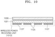
- FIG. 10 is a cross-sectional view of a wireless power receiving unit stacked in a wireless power-driven cooking apparatus according to an embodiment of the disclosure.
- the wireless power receiving unit 1010 may include a receiving coil 1021 for heating a heater 1030, a pickup coil 1127 for supplying power to the control unit 3000, and a communication coil 1125 for short-range communication between the cooking apparatus 1000 and the heating apparatus 2000.
- the pickup coil 1127 and the communication coil 1125 having a small number of windings form one layer, and the receiving coil 1021 used to heat a heater 1130 may form another layer.
- the receiving coil 1021 may include one receiving coil or a plurality of two or more receiving coils located on different layers.
- the pickup coil 1127 and the communication coil 1125 may at least partially share the center.
- the communication coil 1125 may be arranged inwardly and the pickup coil 1127 may be arranged outwardly, and in an embodiment of the disclosure, the communication coil 1125 may be arranged outwardly and the pickup coil 1127 may be arranged inwardly.
- the receiving coil 1021, the pickup coil 1127, and the communication coil 1125 may all be arranged on one layer.
- FIG. 11 is a cross-sectional view of a wireless power receiving unit stacked in a wireless power-driven cooking apparatus according to an embodiment of the disclosure.
- the wireless power receiving unit 1010 may include the receiving coil 1021 for heating the heater 1030, the pickup coil 1127 for supplying power to the control unit 3000, and the communication coil 1125 for short-range communication between the cooking apparatus 1000 and the heating apparatus 2000.
- the pickup coil 1127 and the communication coil 1125 having a smaller number of windings than that of the receiving coil 1021 form one layer, and the receiving coil 1021 used to heat the heater 1130 may form another layer.
- the receiving coil 1021 may include one receiving coil or a plurality of two or more receiving coils arranged on different layers.
- the pickup coil 1127 and the communication coil 1125 may be arranged with a separate center. For example, even when the pickup coil 1127 and the communication coil 1125 are arranged on the same layer, they may not share the center.
- FIG. 12 is a cross-sectional view of a wireless power receiving unit in a wireless power-driven cooking apparatus according to an embodiment of the disclosure.
- the wireless power receiving unit 1010 according to FIG. 12 may include a first receiving coil unit 1241, a second receiving coil unit 1243, a pickup coil 1245, and a communication coil 1247.
- the first receiving coil unit 1241 having the largest number of windings may be arranged on the top, under which the second receiving coil unit 1243, the pickup coil 1245, and the communication coil 1247 may be arranged, at least partially sharing the center.
- the communication coil 1247, the pickup coil 1245, and the second receiving coil unit 1243 may be sequentially arranged in a direction away from the center.
- the communication coil 1247, the pickup coil 1245, and the second receiving coil unit 1243 may form a concentric circle.
- the communication coil 1247, the pickup coil 1245, and the second receiving coil unit 1243 may be arranged on one layer, but one coil or two coils of these coils may not share the center with each other.
- an NFC tag may be used as the communication coil 1247 to inform that the cooking apparatus 1000 to is stationed on the heating apparatus 2000.
- the communication coil 1247 may be arranged separately without sharing the center with the pickup coil 1245 or the second receiving coil unit 1243.
- the pickup coil 1245 may be separately arranged on the same layer so as to be close to the control unit 3000.
- an order in which the three coils are arranged in a direction away from the center shared at least partially thereby may be changed as follows.
- Arrangement according to FIG. 12 may be mainly used when the number of coil windings of the first receiving coil unit 1241 is largest.
- the arrangement according to FIG. 12 may be appropriate.
- the first receiving coil unit 1241 having the largest number of windings may be arranged under the second receiving coil unit 1243, the pickup coil 1245, and the communication coil 1247, which may be arranged on the same layer while at least partially sharing the center.
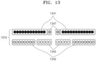
- FIG. 13 is a cross-sectional view of a wireless power receiving unit in a wireless power-driven cooking apparatus according to an embodiment of the disclosure.
- a first receiving coil unit 1341 and a communication coil 1347 may form one layer, and a second receiving coil unit 1343 and a pickup coil 1345 may be arranged on another layer.
- the order of the coils arranged in the direction away from the center on each layer may be changed.
- the communication coil 1347 may be arranged outwardly from the center with respect to the first receiving coil unit 1341.
- the pickup coil 1345 may also be arranged outwardly from the center with respect to the second receiving coil unit 1343.
- the number of windings of the communication coil 1347 is less than that of other coils, such that the communication coil 1347 may be arranged on the same layer as that of the first receiving coil unit 1341 without sharing the center with the first receiving coil unit 1341.
- the arrangement of the wireless power receiving unit 1010 according to FIG. 13 may be used when the number of windings of the first receiving coil unit 1341 is greater than that of the second receiving coil unit 1343 by a small difference.
- FIG. 14 is a cross-sectional view of a wireless power receiving unit of a wireless power-driven cooking apparatus according to an embodiment of the disclosure.
- a communication coil 1447 may be arranged outwardly while sharing the center with the first receiving coil unit 1441.
- a second receiving coil unit 1443 and a pickup coil 1445 may be arranged while sharing the center.
- the communication coil 1447 and the first receiving coil unit 1441 may be arranged under the second receiving coil unit 1443 and the pickup coil 1445, which may be arranged on the communication coil 1447 and the first receiving coil unit 1441.
- FIG. 15 is a flowchart for describing a method of driving a wireless power-driven cooking apparatus having a structure in which receiving coils are stacked, according to an embodiment of the disclosure.
- a first receiving coil unit and a second receiving coil unit of the cooking apparatus may wirelessly receive power from a wireless power transmitting unit of a heating apparatus.
- the first receiving coil unit and/or the second receiving coil unit of the cooking apparatus may output energy based on the received power.
- the first receiving coil unit or the second receiving coil unit of the cooking apparatus may perform heating output.
- the heating output may be replaced with power output of another type.
- the power output of another type may be motor rotation output, battery charging output, etc.
- the use of power output from the first receiving coil unit and the second receiving coil unit may vary according to a type of a load.
- the first receiving coil unit and the second receiving coil unit may be arranged on different layers in a longitudinal direction of the center shared thereby.
- the first receiving coil unit and the second receiving coil unit at least partially share the center, it may mean that at least a part of the center of the first receiving coil unit and at least a part of the center of the second receiving coil unit overlap with each other and may not necessarily match each other completely in a mathematical and physical manner.
- the pickup coil may supply power for controlling the cooking apparatus driven by wireless power to a control unit.
- the pickup coil may be arranged under or on the first receiving coil unit and the second receiving coil unit, or on the same layer as one of the first receiving coil unit and the second receiving coil unit.
- FIG. 16 is a block diagram of a heater-type wireless power-driven cooking system including a wireless power receiving unit, according to an embodiment of the disclosure.
- a wireless power-driven cooking system 1600 may include the heater-type cooking apparatus 1000a and the heating apparatus 2000.
- the cooking apparatus 1000a may include the wireless power receiving unit 1010, a heating unit 1610, a control unit 3000, and a power supply unit 4000.
- the cooking apparatus 1000a and the heating apparatus 2000 may be home appliances that may be sold as separate products.
- the power supply unit 4000 may be an SMPS that receives AC power from a pickup coil 1607 and supplies DC power to the control unit 3000.
- the power supply unit 4000 may include, in addition to the control unit 3000, an inverter and/or a converter that supplies AC/DC power, when another component in the cooking apparatus 1000a or the heating apparatus 2000 requires AC/DC power rather than commercial AC power.
- the power supply unit 4000 may include a rectifying circuit for converting commercial AC power to DC power source and maintain a DC voltage through a DC link capacitor.
- An inverter connected to a DC connection capacitor may generate AC power of various frequencies and magnitudes required by the cooking apparatus 1000a.
- the converter may generate DC power of various magnitudes required by the cooking apparatus 1000a.
- the control unit 3000 may be used to control the cooking apparatus 1000a. The control unit will be described in more detail with reference to FIG. 18 .
- the first receiving coil unit 1601, the second receiving coil unit 1603, the pickup coil 1607, and the communication coil 1605 of the wireless power receiving unit 1010 in the cooking apparatus 1000a may wirelessly receive AC power by sharing magnetic flux with a transmitting coil included in the wireless power transmitting unit 2010.
- the wireless power receiving unit 1010 may further include a plurality of receiving coil units such as a third receiving coil unit, a fourth receiving coil unit, etc., which are not shown, as necessary.
- the first receiving coil unit 1601, the second receiving coil unit 1603, the pickup coil 1607, and the communication coil 1605 may be stacked according to the number of windings of each of them.
- a detailed embodiment of the disclosure regarding the stacking has been described in detail with reference to FIG. 9A and 10 through 14 , and thus will be omitted herein.
- the first receiving coil unit 1601 and/or the second receiving coil unit 1603 may heat a heating unit 1610.
- the heating unit 1610 may include a plurality of different heating units connected to the first receiving coil unit 1601 and the second receiving coil unit 1603, respectively.
- the plurality of heating units may have different heating outputs.
- the first receiving coil unit 1601 and the second receiving coil unit 1603 may be electrically insulated from each other and may be electrically connected to each other.
- a plurality of heating units included in the heating unit 1610 may be independently heated.
- the first receiving coil unit 1601 and the second receiving coil unit 1603 When the first receiving coil unit 1601 and the second receiving coil unit 1603 are electrically connected, upon reception of power wirelessly transferred through the wireless power transmitting unit 2010, the first receiving coil unit 1601 and the second receiving coil unit 1603 may be simultaneously driven to generate one electrical output resulting from combining electrical output from each of the first receiving coil unit 1601 and the second receiving coil unit 1603. In this case, the first receiving coil unit 1601 and/or the second receiving coil unit 1603 may heat the heating unit 1610.
- one receiving coil unit having the same number of windings as a sum of the number of windings of the first receiving coil unit 1601 and the number of windings of the second receiving coil unit 1603 or having the same inductance as that of the first receiving coil unit 1601 and the second receiving coil unit 1603 may output the same output in a state where the first receiving coil unit 1601 and the second receiving coil unit 1603 are stacked. For example, when the first receiving coil unit 1601 and the second receiving coil unit 1603 are electrically connected, one heating level may be output.
- the heating apparatus 2000 may include a wireless power transmitting unit 2010 which may include a transmitting coil.
- the heating apparatus 2000 may be referred to as a station.
- the wireless power transmitting unit 2010 may receive commercial AC power and may receive AC power generated by a separate power source (not shown).
- the AC power input to the wireless power transmitting unit 2010 may be wirelessly transmitted to the wireless power receiving unit 1010 in the cooking apparatus 1000a through the wireless power transmitting unit 2010.
- the cooking system 1600 may be an integrated home appliance including both the cooking apparatus 1000a and the heating apparatus 2000.
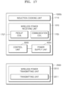
- FIG. 17 is a block diagram of an induction-type wireless power-driven cooking system including a wireless power receiving unit, according to an embodiment of the disclosure.
- a cooking apparatus 1000b may include the wireless power receiving unit 1010, the control unit 3000, the power supply unit 4000, and an induction cooking unit 1710.
- the induction cooking unit 1710 may be a pot, a frying pan, etc., including induction heating metal.
- the power supply unit 4000 may be an SMPS that receives AC power from a pickup coil 1707 and supplies DC power to the control unit 3000.
- the communication coil 1705 may be used to transmit a sensing signal to a communication coil included in the heating apparatus 2000 when the induction cooking unit 1710 is placed on the heating apparatus 2000.
- the communication coil 1705 may be referred to as an NFC antenna coil and may use short-range communication such as NFC or Bluetooth.
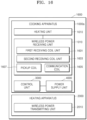
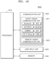
- FIG. 18 is a block diagram of a control unit of a wireless power-driven cooking apparatus according to an embodiment of the disclosure.
- the control unit 3000 included in the wireless power-driven cooking apparatuses 1000a and 1000b may include a processor 1810, a communication unit 1820, a user input unit 1830, and a memory 1840.
- the wireless power-driven cooking apparatuses 1000a and 1000b may be implemented by a larger or smaller number of elements than the illustrated elements.
- the control unit 3000 may further include an output unit, a display unit, and the like.
- the processor 1810 may generally control the overall operation of the wireless power-driven cooking apparatus 1600 according to an embodiment of the disclosure.
- the processor 1810 may control the communication unit 1820, the user input unit 1830, the memory 1840, etc., overall, by executing programs stored in the memory 1840.
- the processor 1810 may include an artificial intelligence (Al) processor for generating a learning network model, without being limited thereto.
- the AI processor may be implemented as a separate chip from the processor 1710.
- the AI processor may be a general-purpose chip.
- a short-range wireless communication unit 1821 may include a Bluetooth communication unit, a Bluetooth Low Energy (BLE) communication unit, an NFC unit, a wireless local area network (WLAN) (WiFi) communication unit, a ZigBee communication unit, an IrDA communication unit, a WiFi Direct (WFD) communication unit, an ultra-wideband (UWB) communication unit, an Ant+ communication unit, etc., without being limited thereto.
- the short-range communication unit 1821 may inform the heating apparatus 2000 of the presence of the cooking apparatus 1000a and 1000b by transmitting a signal to the heating apparatus 2000 through the communication coils 1605 and 1705 when the cooking apparatuses 1000a and 1000b are placed on the heating apparatus 2000.
- the heating apparatus 2000 may block or reduce wireless power output based on sensing information of the cooking apparatuses 1000a and 1000b.
- the communication coil may use a communication scheme using NFC, like an NFC antenna coil.
- NFC short-range communication
- the heating apparatus 2000 may sense that the cooking apparatuses 1000a and 1000b are placed on the heating apparatus 2000.
- the cooking apparatus 1000 and the heating apparatus 2000 may be one home appliance.
- the heating apparatus 2000 may also obtain identification information of the cooking apparatus 1000.
- a remote-range communication unit 1823 is not necessary for the control unit 3000 according to an embodiment of the disclosure, but may be used to communicate with an external device (a mobile device or a computing device) when the cooking apparatus 1000 is remotely controlled by the external device in an Internet of Things (loT) environment.
- the user input unit 1830 may mean a means for inputting data for controlling the cooking apparatus 1000 by a user.
- the user input unit 1830 may include, but not limited to, a keypad, a dome switch, a touch pad (a contact-capacitive type, a pressure-resistive type, an infrared sensing type, a surface ultrasonic conduction type, an integral strain gauge type, a piezoelectric effect type, etc.), a jog wheel, a jog switch, a dial switch, or the like.
- the user input unit 1830 may include a button unit including a power button, a heating control button, and the like.
- the user input unit 1830 may further include a microphone (not shown) for receiving user's voice input.
- the microphone may receive an external audio signal and process the received audio signal into electric data.
- a microphone may receive an audio signal (e.g., a voice command) from an external device or speaker.
- the microphone may use various noise cancellation algorithms for canceling noise occurred during reception of the external audio signal.
- the memory 1840 may store a program for processing and control by the processor 1810, and store input/output data (e.g., a fine dust level, temperature and humidity data, a gas level, notification setting, filter replacement cycle information, etc.).
- the memory 1840 may include a storage medium of at least one type of a flash memory type, a hard disk type, a multimedia card micro type, a card type memory (e.g., a secure digital (SD) or extreme digital (XD) memory, etc.), a random-access memory (RAM), a static random-access memory (SRAM), a read-only memory (ROM), an electrically erasable programmable read-only memory (EEPROM), a programmable read-only memory (PROM), a magnetic memory, a magnetic disk, or an optical disk.
- the programs stored in the memory 1840 may be classified into a plurality of modules according to functions thereof.
- At least one AI model may be stored in the memory 1840.
- a function related to AI according to the disclosure may be performed through a processor and a memory.
- the processor may include one processor or a plurality of processors.
- one processor or a plurality of processors may include a general-purpose processor such as a CPU, an application processor (AP), a digital signal processor (DSP), etc., a graphic-dedicated processor such as a GPU, a vision processing unit (VPU), etc., or an Al-dedicated processor such as a neural processing unit (NPU).
- One processor or a plurality of processors may control data to be processed according to a predefined operation rule or AI model stored in the memory.
- the Al-dedicated processor may be designed as a hardware structure specialized for processing a specific AI model.
- the predefined operation rule or AI model may be made through training.
- the AI model is made through training, it may mean that a basic AI model is trained based on a learning algorithm by using multiple training data, such that the predefined operation rule or AI model configured to execute desired characteristics (or purpose) may be made.
- Such training may be performed by an apparatus on which AI according to the disclosure is implemented, or by a separate server and/or system.
- Examples of a learning algorithm may include, but not limited to, supervised learning, unsupervised learning, semi-supervised learning, or reinforcement learning.
- the AI model may include a plurality of neural network layers. Each of the plurality of neural network layers may have a plurality of weight values, and perform a neural network operation through an operation between an operation result of a previous layer and the plurality of weight values.
- the plurality of weight values of the plurality of neural network layers may be optimized by a training result of the AI model. For example, the plurality of weight values may be updated to reduce or minimize a loss value or a cost value obtained in the AI model during a training process.
- the AI neural network may include, but not limited to, a deep neural network (DNN), e.g., a convolutional neural network (CNN), a DNN, a recurrent neural network (RNN), a restricted Boltzmann machine (RBM), a deep belief network (DBN), a bidirectional recurrent deep neural network (BRDNN), a deep Q-network, ETC.
- DNN deep neural network
- CNN convolutional neural network
- RNN recurrent neural network
- RBM restricted Boltzmann machine
- DBN deep belief network
- BNN bidirectional recurrent deep neural network
- ETC a deep Q-network
- the method according to an embodiment of the disclosure may be random-access implemented in the form of program commands that may be executed through various computer means and recorded on a computer-readable recording medium.
- the computer-readable recording medium may include a program command, a data file, a data structure, etc., alone or in a combined manner.
- the program command recorded on the computer-readable recording medium may be a program command specially designed and configured for the disclosure or a program command known to be used by those skilled in the art of the computer software field.
- Examples of the computer-readable recording medium may include magnetic media such as hard disk, floppy disk, and magnetic tape, optical media such as compact disk read only memory (CD-ROM) and digital versatile disk (DVD), magneto-optical media such as floptical disk, and a hardware device especially configured to store and execute a program command, such as read only memory (ROM), random access memory (RAM), flash memory, etc.
- Examples of the program command may include not only a machine language code made by a compiler, but also a high-level language code executable by a computer using an interpreter.
- An embodiment of the disclosure may be implemented using a recording medium including a computer-executable instruction such as a computer-executable programming module.
- the computer-readable recording medium may be an available medium that is accessible by a computer, and include all of a volatile medium, a non-volatile medium, a separated medium, and a non-separated medium.
- the computer-readable recording medium may also include both a computer storage medium and a communication medium.
- the computer storage medium may include all of a volatile medium, a non-volatile medium, a separated medium, and a non-separated medium, which are implemented by a method or technique for storing information such as a computer-readable instruction, a data structure, a programming module, or other data.
- the communication medium may include a computer-readable instruction, a data structure, a programming module, or other data of a modulated data signal like carriers, or other transmission mechanisms, and include an information delivery medium.
- some embodiments of the disclosure may be implemented by a computer program including a computer-executable instruction such as a computer program executed by a computer, or a computer program product.
- the machine-readable storage medium may be provided in the form of a non-transitory storage medium.
- the term 'non-transitory storage medium' simply means that the storage medium is a tangible device, and does not include a signal (e.g., an electromagnetic wave), but this term does not differentiate between where data is semi-permanently stored in the storage medium and where the data is temporarily stored in the storage medium.
- the 'non-transitory storage medium' may include a buffer in which data is temporarily stored.
- a method according to an embodiment of the disclosure may be included and provided in a computer program product.
- the computer program product may be traded as a product between a seller and a buyer.
- the computer program product may be distributed in the form of a machine-readable storage medium (e.g., compact disc read only memory (CD-ROM)), or be distributed (e.g., downloaded or uploaded) online via an application store (e.g., PlayStore TM ), or between two user devices (e.g., smart phones) directly.
- an application store e.g., PlayStore TM
- two user devices e.g., smart phones
- at least a part of the computer program product e.g., a downloadable app
- the machine-readable storage medium such as memory of the manufacturer's server, a server of the application store, or a relay server.
- a cooking apparatus driven by wireless power including a wireless power receiving unit configured to wirelessly receive power from a wireless power transmitting unit and a processor configured to control the wireless power receiving unit.
- the wireless power receiving unit the cooking apparatus includes a first receiving coil and a second receiving coil having a shared center with the first receiving coil whereby the second receiving coil shares at least a part of a center of the first receiving coil, the first receiving coil and the second receiving coil being arranged on different layers along a longitudinal direction of the shared center.
- each of a pickup coil and a communication coil may be placed in a different layer.
- the cooking apparatus driven by wireless power may include a station(a heating apparatus) including a wireless power transmitting unit which wirelessly provides power to the wireless power receiving unit.
- the cooking apparatus driven by wireless power the communication coil may transmit a signal indicating the cooking apparatus is stationed on the heating apparatus to a communicatino coil of the heating apparatus.
- a cooking apparatus driven by wireless power including a wireless power receiving unit configured to wirelessly receive power from a wireless power transmitting unit and a processor configured to control the wireless power receiving unit.
- the wireless power receiving unit the cooking apparatus includes a first receiving coil and a second receiving coil not having a shared center with the first receiving coil.
- the cooking apparatus driven by wireless power includes the first receiving coil and the second receiving coil being arranged on different layers along a longitudinal direction.
- a cooking apparatus driven by wireless power may include stacking a plurality of receiving coils having different heating levels whereby a planar area of the cooking apparaus may be reduced.
- the wireless power-driven cooking apparatus may maximize the spatial efficiency of the cooking apparatus by stacking a pickup coil configured to produce power and a communication coil configured to transmit a signal upon placement of the cooking apparatus on a station.
- the 'non-transitory storage medium' may include a buffer in which data is temporarily stored.
- a method according to an embodiment of the disclosure may be included and provided in a computer program product.
- the computer program product may be traded as a product between a seller and a buyer.
- the computer program product may be distributed in the form of a machine-readable storage medium (e.g., compact disc read only memory (CD-ROM)), or be distributed (e.g., downloaded or uploaded) online via an application store (e.g., PlayStore TM ), or between two user devices (e.g., smart phones) directly.
- an application store e.g., PlayStore TM
- two user devices e.g., smart phones
- at least a part of the computer program product e.g., a downloadable app
- the machine-readable storage medium such as memory of the manufacturer's server, a server of the application store, or a relay server.
Landscapes
- Engineering & Computer Science (AREA)
- Computer Networks & Wireless Communication (AREA)
- Power Engineering (AREA)
- Physics & Mathematics (AREA)
- Electromagnetism (AREA)
- Food Science & Technology (AREA)
- Induction Heating Cooking Devices (AREA)
Applications Claiming Priority (2)
| Application Number | Priority Date | Filing Date | Title |
|---|---|---|---|
| KR1020210106940A KR20230024776A (ko) | 2021-08-12 | 2021-08-12 | 무선전력전송을 이용하는 기기에서 다중 수신 코일을 구성하는 방법 및 장치 |
| PCT/KR2022/012116 WO2023018296A1 (ko) | 2021-08-12 | 2022-08-12 | 무선전력전송을 이용하는 기기에서 다중 수신 코일을 구성하는 방법 및 장치 |
Publications (2)
| Publication Number | Publication Date |
|---|---|
| EP4366126A1 true EP4366126A1 (de) | 2024-05-08 |
| EP4366126A4 EP4366126A4 (de) | 2024-10-23 |
Family
ID=85200170
Family Applications (1)
| Application Number | Title | Priority Date | Filing Date |
|---|---|---|---|
| EP22856289.8A Pending EP4366126A4 (de) | 2021-08-12 | 2022-08-12 | Verfahren und vorrichtung zur konfiguration mehrerer empfangsspulen in einer vorrichtung mit drahtloser stromübertragung |
Country Status (5)
| Country | Link |
|---|---|
| US (1) | US20230262850A1 (de) |
| EP (1) | EP4366126A4 (de) |
| KR (1) | KR20230024776A (de) |
| CN (1) | CN117837050A (de) |
| WO (1) | WO2023018296A1 (de) |
Family Cites Families (7)
| Publication number | Priority date | Publication date | Assignee | Title |
|---|---|---|---|---|
| JP5235836B2 (ja) * | 2009-10-20 | 2013-07-10 | 三菱電機株式会社 | 誘導加熱調理装置 |
| EP2906083A1 (de) * | 2012-10-11 | 2015-08-19 | Arçelik Anonim Sirketi | Auf einer induktionsherdplatte betriebenes, drahtloses kochgerät |
| KR102357033B1 (ko) * | 2015-12-09 | 2022-01-28 | 주식회사 위니아딤채 | 전기 가열 조리기의 가열장치 어셈블리 |
| KR101931421B1 (ko) * | 2017-01-18 | 2019-03-13 | 엘지전자 주식회사 | 유도 가열 및 무선 전력 전송 장치 |
| KR101995109B1 (ko) * | 2017-04-10 | 2019-07-01 | 엘지전자 주식회사 | 전자유도가열식 조리기기 |
| KR20200101825A (ko) * | 2019-02-20 | 2020-08-28 | 엘지전자 주식회사 | 무선 유도가열 밥솥 및 이를 포함하는 무선 유도가열 시스템 |
| EP4395128A4 (de) * | 2022-01-27 | 2025-01-22 | Samsung Electronics Co., Ltd. | Verfahren zur ausgabe von informationen über ein gargerät und drahtlose stromübertragungsvorrichtung dafür |
-
2021
- 2021-08-12 KR KR1020210106940A patent/KR20230024776A/ko active Pending
-
2022
- 2022-08-12 EP EP22856289.8A patent/EP4366126A4/de active Pending
- 2022-08-12 CN CN202280055470.0A patent/CN117837050A/zh active Pending
- 2022-08-12 WO PCT/KR2022/012116 patent/WO2023018296A1/ko not_active Ceased
-
2023
- 2023-04-27 US US18/140,111 patent/US20230262850A1/en active Pending
Also Published As
| Publication number | Publication date |
|---|---|
| US20230262850A1 (en) | 2023-08-17 |
| WO2023018296A1 (ko) | 2023-02-16 |
| EP4366126A4 (de) | 2024-10-23 |
| CN117837050A (zh) | 2024-04-05 |
| KR20230024776A (ko) | 2023-02-21 |
Similar Documents
| Publication | Publication Date | Title |
|---|---|---|
| US20130175874A1 (en) | Wireless energy transfer for promotional items | |
| US20240186828A1 (en) | Method and device for controlling amount of power supplied to load in device using wireless power transmission | |
| US20230233020A1 (en) | Method of outputting information regarding cooking appliance and wireless power transmission apparatus therefor | |
| JP2016134355A (ja) | 非接触給電機能付き誘導加熱調理器およびその制御方法 | |
| KR20160028537A (ko) | 휴대용 충전기 | |
| CN210018894U (zh) | 烹饪器具 | |
| CN116888857A (zh) | 使用无线功率传递系统的虚拟ac功率信号传递 | |
| EP3989678A1 (de) | Kocher mit drahtloser induktionserwärmung und system mit drahtloser induktionserwärmung damit | |
| KR20200101825A (ko) | 무선 유도가열 밥솥 및 이를 포함하는 무선 유도가열 시스템 | |
| EP4366126A1 (de) | Verfahren und vorrichtung zur konfiguration mehrerer empfangsspulen in einer vorrichtung mit drahtloser stromübertragung | |
| JPH10165294A (ja) | 誘導加熱式炊飯器 | |
| US20240195223A1 (en) | Wireless power transmission device and control method of the same | |
| KR102438929B1 (ko) | 모듈러 조리기기 시스템 및 그 동작 방법 | |
| EP4344020B1 (de) | Kochgerät mit mehrfachleistungsstruktur | |
| EP4354705A1 (de) | Vorrichtung zur drahtlosen stromübertragung und verfahren zur positionierung einer kochvorrichtung einer vorrichtung zur drahtlosen stromübertragung | |
| JP2010288429A (ja) | 充電台 | |
| CN119138103A (zh) | 用于检测空加热的家用电器和电力传输装置 | |
| US20230403767A1 (en) | Method and apparatus for electromagnetic induction | |
| US20240171016A1 (en) | Wireless power transmission device and control method thereof | |
| JPWO2020240740A1 (ja) | 冷却装置、及び調理システム | |
| CN107411533A (zh) | 烹饪器具及其无线供电系统 | |
| KR20230067953A (ko) | 무선 전력 전송 장치 및 무선 전력 전송 장치의 조리 기기 위치 식별 방법 | |
| KR20230115749A (ko) | 조리 기기에 관한 정보를 출력하는 방법 및 이를 위한 무선 전력 전송 장치 | |
| US20240397588A1 (en) | Method and device for eliminating noise of cooking device by using wireless power transmission | |
| JP2018097990A (ja) | 磁界誘導加熱調理器および磁界誘導加熱装置 |
Legal Events
| Date | Code | Title | Description |
|---|---|---|---|
| STAA | Information on the status of an ep patent application or granted ep patent |
Free format text: STATUS: THE INTERNATIONAL PUBLICATION HAS BEEN MADE |
|
| PUAI | Public reference made under article 153(3) epc to a published international application that has entered the european phase |
Free format text: ORIGINAL CODE: 0009012 |
|
| STAA | Information on the status of an ep patent application or granted ep patent |
Free format text: STATUS: REQUEST FOR EXAMINATION WAS MADE |
|
| 17P | Request for examination filed |
Effective date: 20240131 |
|
| AK | Designated contracting states |
Kind code of ref document: A1 Designated state(s): AL AT BE BG CH CY CZ DE DK EE ES FI FR GB GR HR HU IE IS IT LI LT LU LV MC MK MT NL NO PL PT RO RS SE SI SK SM TR |
|
| A4 | Supplementary search report drawn up and despatched |
Effective date: 20240923 |
|
| RIC1 | Information provided on ipc code assigned before grant |
Ipc: H02J 50/12 20160101ALI20240917BHEP Ipc: A47J 27/21 20060101ALI20240917BHEP Ipc: H05B 6/12 20060101ALI20240917BHEP Ipc: H02J 50/80 20160101ALI20240917BHEP Ipc: H02J 50/40 20160101ALI20240917BHEP Ipc: H02J 50/10 20160101ALI20240917BHEP Ipc: H02J 50/00 20160101AFI20240917BHEP |
|
| DAV | Request for validation of the european patent (deleted) | ||
| DAX | Request for extension of the european patent (deleted) |