EP4365922A1 - Nottaster für eine fluchttürsicherung - Google Patents
Nottaster für eine fluchttürsicherung Download PDFInfo
- Publication number
- EP4365922A1 EP4365922A1 EP23191814.5A EP23191814A EP4365922A1 EP 4365922 A1 EP4365922 A1 EP 4365922A1 EP 23191814 A EP23191814 A EP 23191814A EP 4365922 A1 EP4365922 A1 EP 4365922A1
- Authority
- EP
- European Patent Office
- Prior art keywords
- housing
- actuating element
- emergency button
- cover
- designed
- Prior art date
- Legal status (The legal status is an assumption and is not a legal conclusion. Google has not performed a legal analysis and makes no representation as to the accuracy of the status listed.)
- Pending
Links
Images


Classifications
-
- H—ELECTRICITY
- H01—ELECTRIC ELEMENTS
- H01H—ELECTRIC SWITCHES; RELAYS; SELECTORS; EMERGENCY PROTECTIVE DEVICES
- H01H3/00—Mechanisms for operating contacts
- H01H3/02—Operating parts, i.e. for operating driving mechanism by a mechanical force external to the switch
- H01H3/022—Emergency operating parts, e.g. for stop-switch in dangerous conditions
-
- H—ELECTRICITY
- H01—ELECTRIC ELEMENTS
- H01H—ELECTRIC SWITCHES; RELAYS; SELECTORS; EMERGENCY PROTECTIVE DEVICES
- H01H13/00—Switches having rectilinearly-movable operating part or parts adapted for pushing or pulling in one direction only, e.g. push-button switch
- H01H13/02—Details
- H01H13/12—Movable parts; Contacts mounted thereon
- H01H13/14—Operating parts, e.g. push-button
-
- G—PHYSICS
- G05—CONTROLLING; REGULATING
- G05G—CONTROL DEVICES OR SYSTEMS INSOFAR AS CHARACTERISED BY MECHANICAL FEATURES ONLY
- G05G1/00—Controlling members, e.g. knobs or handles; Assemblies or arrangements thereof; Indicating position of controlling members
- G05G1/02—Controlling members for hand actuation by linear movement, e.g. push buttons
-
- H—ELECTRICITY
- H01—ELECTRIC ELEMENTS
- H01H—ELECTRIC SWITCHES; RELAYS; SELECTORS; EMERGENCY PROTECTIVE DEVICES
- H01H13/00—Switches having rectilinearly-movable operating part or parts adapted for pushing or pulling in one direction only, e.g. push-button switch
- H01H13/02—Details
- H01H13/04—Cases; Covers
- H01H13/06—Dustproof, splashproof, drip-proof, waterproof or flameproof casings
-
- H—ELECTRICITY
- H01—ELECTRIC ELEMENTS
- H01H—ELECTRIC SWITCHES; RELAYS; SELECTORS; EMERGENCY PROTECTIVE DEVICES
- H01H3/00—Mechanisms for operating contacts
- H01H3/02—Operating parts, i.e. for operating driving mechanism by a mechanical force external to the switch
- H01H3/022—Emergency operating parts, e.g. for stop-switch in dangerous conditions
- H01H2003/0233—Emergency operating parts, e.g. for stop-switch in dangerous conditions for alarm triggering, e.g. fire alarm, emergency off switches operated by breaking a glass
Definitions
- the invention relates to an emergency button for an escape door security system.
- the emergency button comprises a translationally movable actuating element and a housing area that surrounds the actuating element.
- the actuating element can be moved into an unactuated position and into an actuated position.
- the DE102017100476 A1 discloses such an emergency button, as in Figure 1 shown.
- the emergency button 1 in Figure 1 comprises a surface-mounted housing 10 with a housing base body 11 and a cover 12.
- An actuating element 2 is arranged on the cover 12.
- the cover 12 comprises a circular opening 13 and surrounds the actuating element 2.
- An actuating element 2 is covered by a transparent pane that moves with the actuating element 2 and fills the opening 13.
- the disadvantage of this is that the pane is sensitive to impact and breaks easily.
- the object of the invention to provide an emergency button that is particularly resistant to impact. Nevertheless, the emergency button should preferably only be activated in an emergency.
- the emergency button comprises a housing area that surrounds the actuating element.
- the housing area is designed like a depression.
- the term "hollow-like" means that the housing area corresponds to a depression with rounded walls.
- the housing area can thus be designed as a hollow or a trough.
- the hollow or trough can include a passage through which the actuating element protrudes.
- the hollow-like housing area makes it possible to arrange the actuating element in a protected position in the hollow. This prevents unintentional actuation outside of an emergency.
- the actuating element is easy to find, as the hollow guides a person's hand to the actuating element.
- the actuating element itself has a small diameter and is therefore insensitive to impact. This means that the emergency button can be operated without the emergency button and/or the person operating it being injured.
- the emergency button is used to unlock an electromagnetic or electromechanical door lock.
- Teen can press the actuating element without authenticating themselves and thereby unlock the door lock.
- the actuating element preferably presses a switch.
- the switch then interrupts at least one circuit. The person fleeing in this way is referred to below as the user.
- the emergency button is usually installed on or in the wall next to a door.
- the terms “front”, “rear” and “side” are used accordingly in this disclosure.
- the housing area is stationary. This means that the actuating element moves relative to the housing area from the non-actuated position to the actuated position.
- the housing area can thus be designed to be stationary when the actuating element moves from the non-actuated to the actuated position.
- the housing area is preferably part of a housing that is to be permanently installed on or in the wall.
- the emergency button preferably comprises a housing, in particular a surface-mounted housing.
- the housing can comprise a cover.
- the housing region can be formed as part of the housing, in particular as part of the cover.
- the emergency button can only include a cover for a housing.
- this can be a cover that can be attached to a flush-mounted box.
- the flush-mounted box and the cover together form a housing for the emergency button.
- the housing area comprises a recessed edge, wherein the actuating element is arranged flat or set back from the recessed edge in the unactuated position.
- the edge of the recess faces the user. This means that the edge of the recess faces forward.
- the recess Due to the flat or recessed arrangement of the actuating element to the edge of the recess, the recess completely surrounds the actuating element from a side view. This is particularly effective at preventing unwanted actuation.
- the housing area comprises a well base.
- the well base is opposite the well edge. When installed, the well base is directed rearward toward the wall.
- the well base can comprise the open passage for the actuating element.
- the actuating element can move relative to the well base to actuate the switch.
- the actuating element protrudes from the base of the recess, in particular to the front, in the non-actuated position. This facilitates deliberate actuation of the actuating element.
- the actuating element can comprise an actuating stamp for actuating the switch.
- the actuating stamp can comprise a coloured marking, e.g. red.
- the actuating element can comprise a transparent cap.
- both the cap and the actuating plunger move from the unactuated to the actuated position when the actuating element is actuated.
- cap and the actuating plunger are firmly connected to one another, i.e. positively, force-lockingly and/or positively.
- the transparent cap can replace the usual glass.
- the well itself is designed without a lid closure. This means that the user can touch and operate the actuating element, in particular on the cap, directly without any obstacle.
- the well is designed without a lid at the front.
- the actuating element is designed to move automatically from the actuated position to the non-actuated position.
- a spring is preferably provided here, which moves the actuating element from the actuated position to the non-actuated position.
- the actuating element is thus designed to be restless, i.e. the actuating element does not remain in the actuated position.
- the actuating element in the actuated position, lies flat or substantially flat on the base of the recess. This prevents the user from having to reach through the passage in order to operate the switch via the actuating element.
- the housing area may be designed as an independent component.
- the housing area may therefore be designed as a housing element.
- the housing area may be firmly attached, i.e. positively and/or non-positively, to the rest of the housing.
- the housing region is formed as part of the cover of the housing.
- the housing region in particular the housing element, is formed in the cover of a housing.
- the housing can in particular be the surface-mounted housing.
- the independently formed housing area i.e. the housing element, rests against the rest of the cover from the inside.
- the housing area in particular the housing element, serves to protect against moisture.
- the housing area in particular the housing element, comprises a lip for contact with the actuating element.
- the lip can in particular be circular.
- a sealing element in particular an O-ring, can be provided between the actuating element and the housing area.
- the housing area preferably comprises a step with which the housing area rests against the rest of the housing, in particular against the rest of the cover.
- a sealing element in particular an O-ring, can be provided between the housing element and the rest of the housing, in particular the rest of the cover.
- the housing area in particular the housing element, preferably the lip and/or the step, can be designed to be elastic.
- the lip and/or the step can be designed to be elastic.
- the housing area, in particular the housing element, can be made of the same material and/or in one piece, in particular monolithic.
- the housing area, in particular the housing element, can be made of plastic.
- the housing in particular the cover, comprises an opening.
- the opening can in particular be circular.
- the housing element preferably rests against the opening.
- the housing element preferably partially closes the opening.
- the housing element may comprise a circular outer contour.
- the actuating element together with the switch forms part of a prefabricated assembly.
- a mounting element is provided to fasten the assembly to the housing, in particular the cover.
- the mounting element can be designed as a support ring.
- the support ring can be designed such that the support ring can be used to fasten the assembly in a flush-mounted box.
- the mounting element is attached to the housing, in particular to the cover, in a form-fitting and/or force-fitting manner using fastening elements, e.g. screws.
- the mounting element at least indirectly fastens the housing element to the rest of the housing, in particular to the rest of the cover.
- the mounting element can, for example, at least indirectly press the housing element against the rest of the housing, in particular the rest of the cover, in particular from the inside.
- the emergency button may include lighting elements.
- the lighting elements may be provided to represent a state of the emergency button and/or the door lock, e.g. whether the door lock is locked or unlocked.
- the lighting elements are arranged in such a way that the light emitted by the lighting elements is perceptible to the user in a ring around the actuating element.
- the emergency button comprises a light guide, in particular a light ring.
- the light guide can be provided to transmit the light emitted by the light elements.
- the light guide may be located behind the housing area, in particular behind the housing element.
- the housing area is transparent or translucent in order to transmit the light transmitted by the light guide and/or emitted by the lighting elements.
- the light guide is part of the assembly.
- the light guide presses the housing element against the rest of the housing, in particular against the rest of the cover.
- the housing area in particular the housing element, can comprise ribs.
- the ribs are arranged on the side of the housing area opposite the cooling edge.
- the ribs serve as a point of application for the pressure of the mounting element.
- the housing area, in particular the housing element rests against the light guide with the ribs.
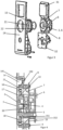
- FIG 2 shows a cover 12 and an assembly 30 of an emergency button 1 for an escape door lock arranged thereon.
- the emergency button 1 is intended to be arranged near a door.
- the cover 12 is part of a surface-mounted housing 10 of the emergency button 1.
- the surface-mounted housing 10 comprises a housing base body 11 and the cover 12.
- the housing base body 11 is essentially a cuboid that is open at the front and is - as in the publication DE102017100476 A1 and in Figure 1 shown - designed.
- the housing body which is in Figure 2
- the cover 12 shown and the assembly 30 together form the emergency button 1 according to the invention.
- the emergency button 1 can comprise an illuminated sign 31 and/or a key switch 32.
- the cover 12 points forwards towards the person who actuates the emergency button 1. This means that the cover 12 is arranged vertically to a building or ground floor.
- the emergency button 1 comprises an actuating element 2.
- the actuating element 2 can be moved translationally between an unactuated position and an actuated position. In the Figures 2 to 4 the actuating element 2 is always shown in the unactuated position.
- the emergency button 1 can be moved by anyone from the unactuated position to the actuated position in order to unlock an electromagnetic or an electromechanical door lock (not shown) so that the escape route is cleared.
- the actuating element 2 interrupts at least one electrical circuit in the actuated position, thereby unlocking the door lock.
- the actuating element 2 actuates a switch on a circuit board 6. In the unactuated position of the actuating element, however, the electrical circuit is closed.
- the cover 12 of the emergency button 1 is designed in several parts and comprises, in addition to a cover base body 14, a housing element 15 which corresponds to the housing area 15 according to the invention.
- the cover base body 14 comprises an opening 13 in which the housing element 15 is rigidly arranged. When the actuating element 2 is actuated, the actuating element 2 moves relative to the housing area 15.
- the actuating element 2 is surrounded by the housing element 15.
- the housing element 15 is designed in the manner of a hollow according to the invention. This makes it possible for at least part of the path that the actuating element 2 travels from the unactuated position to the actuated position to take place in a lateral projection within the surface-mounted housing 10. This means that the risk of unintentional actuation is low.
- the person activating the device hereinafter referred to as the user, can reach into the hollow 18 through the opening 13 and is guided in the direction of the actuating element 2.
- the hollow 18 is without a cover, ie without a lid closure, so that the user can easily reach into the recess 18.
- the actuating element 2 is arranged in the recess so that it can be moved, whereby the movable actuating element 2 itself has a small diameter. This means that the actuating element 2 can also be actuated with a large force without being damaged.
- the actuating element 2 is flush with the housing element 15.
- the front end 3 of the actuating element 2 is thus on a level with a recess edge 16. This allows the maximum path from the non-actuated position to the actuated position for the actuating element 2 to be utilized, with the user having to reach into the recess 18 as little as possible.
- the actuating element 2 does not protrude from the recess 18, so that the risk of accidental actuation is low.
- the recess edge 16 is essentially flat to a front surface 141 of the lid base body 14.
- the actuating element 2 protrudes forwards above a recessed base 17. This allows the user to easily actuate the actuating element 2.
- the recessed base 17 is connected to the actuating element 2.
- the actuating element 2 is designed to be non-latching. This means that the actuating element 2 moves automatically from the actuated position to the non-actuated position immediately after actuation by the force of a spring 20. In the actuated position (not shown), the front end 3 of the actuating element 2 lies essentially flat against the recess base 17.
- the actuating element 2 comprises a red, inner actuating plunger 4, which presses on the switch to interrupt at least one circuit.
- the actuating element 2 comprises a transparent cap 5.
- the cap 5 is rigidly connected to the actuating plunger 4, so that when actuated, the cap 5 moves with the actuating plunger 4.
- the cap 5 forms the front end 3 of the actuating element 2.
- Light elements are arranged on the circuit board 6.
- the light elements are used to indicate different states of the emergency button 1 and/or the door lock.
- the emergency button 1 comprises a light ring 7 through which the light emitted by the light elements is directed forwards.
- the light ring 7 surrounds the actuating element 2.
- the housing element 15 is arranged in front of the light ring 7.
- the housing element 15 is transparent so that the light from the light ring 7 is visible to the user.
- the emergency button 1 comprises a support ring 8.
- the circuit board 6 and/or the light ring 7 are attached to the support ring 8.
- the actuating element 2 is guided on the support ring 8.
- the support ring 8, the light ring 7, the actuating element 2, the spring 20 and the circuit board 6 together form the prefabricated assembly 30.
- the support ring 8 is fastened to the cover base body 14 by fastening elements 9, which are designed here, for example, as screws 9.
- the housing element 15 is designed as a stand-alone component.
- Figure 5 shows the housing element 15 in a perspective view.
- the housing element 15 is ring-shaped in a plan view.
- the housing element 15 comprises a circular outer contour.
- the housing element 15 is pressed against the cover base body 14 by the support ring 8 (see Figure 4 ).
- the housing element 15 is located between the light ring 7 and the cover base body 14.
- the housing element 15 comprises ribs 152 for contact with the light ring 7.
- the housing element 15 comprises a step 150 with which the housing element 15 rests against the cover base body 14.
- annular sealing element 21 is arranged between the housing element 15 and the cover base body 14.
- the housing element 15 comprises a lip 151 with which the housing element 15 rests against the actuating element 2.
- a sealing element 22 is provided between the housing element 15 and the actuating element 2.
Landscapes
- Push-Button Switches (AREA)
Abstract
Description
- Die Erfindung betrifft einen Nottaster für eine Fluchttürsicherung. Der Nottaster umfasst ein translatorisch bewegbares Betätigungselement und einen Gehäusebereich, der das Betätigungselement umgibt. Das Betätigungselement ist in eine unbetätigte Position und in eine betätigte Position bewegbar.
- Die
DE102017100476 A1 offenbart einen derartigen Nottaster, wie inFigur 1 dargestellt. Der Nottaster 1 inFigur 1 umfasst ein Aufputzgehäuse 10 mit einem Gehäusegrundkörper 11 und einen Deckel 12. Ein Betätigungselement 2 ist an dem Deckel 12 angeordnet. Der Deckel 12 umfasst eine kreisförmige Öffnung 13 und umgibt das Betätigungselement 2. Ein Betätigungselement 2 ist von einer sich mit dem Betätigungselement 2 mitbewegenden, transparenten Scheibe verdeckt, die die Öffnung 13 ausfüllt. Nachteilig hieran ist, dass die Scheibe stoßempfindlich ist und leicht bricht. - Es ist daher die Aufgabe der Erfindung, einen Nottaster zur Verfügung zu stellen, der besonders schlagunempfindlich ist. Dennoch soll bevorzugt nur im Notfall der Nottaster betätigt werden.
- Diese Aufgabe wird von dem Patentanspruch 1 gelöst. Vorteilhafte Weiterbildungen der Erfindung sind in den Unteransprüchen angegeben.
- Erfindungsgemäß ist vorgesehen, dass der Nottaster einen Gehäusebereich umfasst, der das Betätigungselement umgibt. Hierbei ist der Gehäusebereich kuhlenartig ausgebildet.
- Insbesondere wird unter kuhlenartig verstanden, dass der Gehäusebereich einer Vertiefung mit abgerundeten Wänden entspricht. Somit kann der Gehäusebereich als eine Kuhle oder als eine Mulde ausgebildet sein. Die Kuhle oder Mulde kann einen Durchlass umfassen, durch den das Betätigungselement ragt.
- Durch den kuhlenartigen Gehäusebereich ist es möglich, das Betätigungselement geschützt in der Kuhle anzuordnen. Hierdurch wird eine unbeabsichtigte Betätigung außerhalb eines Notfalls verhindert. Zugleich ist das Betätigungselement gut auffindbar, da die Kuhle eine Hand einer Person zu dem Betätigungselement führt. Das Betätigungselement selbst umfasst einen geringen Durchmesser und ist daher schlagunempfindlich. Hierdurch ist der Nottaster bedienbar, ohne dass der Nottaster und/oder die betätigende Person beschädigt wird.
- Der Nottaster dient dazu, eine elektro-magnetische oder eine elektro-mechanische Türverriegelung zu entriegeln. Hierbei kann jede Person, ohne sich authentifizieren, auf das Betätigungselement drücken und damit die Türverriegelung entriegeln. Hierbei drückt das Betätigungselement bevorzugt auf einen Schalter. Der Schalter unterbricht daraufhin zumindest einen Stromkreis. Die derart fliehende Person wird im Folgenden als Benutzer bezeichnet.
- Üblicherweise wird der Nottaster an oder in der Wand neben einer Tür installiert. Die Begriffe "vorne", "hinten", "seitlich" werden in dieser Offenbarung entsprechend verwendet. Bevorzugt ist vorgesehen, dass der Gehäusebereich feststehend ist. D. h. das Betätigungselement bewegt sich gegenüber dem Gehäusebereich von der unbetätigten Position in die betätigte Position. Somit kann der Gehäusebereich bei einer Bewegung des Betätigungselements von der unbetätigten in die betätigte Position feststehend ausgebildet sein. Bevorzugt ist der Gehäusebereich ein Teil eines fest an oder in der Wand zu installierenden Gehäuses.
- Bevorzugt umfasst der Nottaster ein Gehäuse, insbesondere ein Aufputzgehäuse. Das Gehäuse kann einen Deckel umfassen. Der Gehäusebereich kann als Teil des Gehäuses, insbesondere als Teil des Deckels, ausgebildet sein.
- Alternativ kann der Nottaster nur einen Deckel für ein Gehäuse umfassen. Beispielsweise kann dieses ein Deckel, der auf einer Unterputzdose befestigtbar sein. Die Unterputzdose und der Deckel bilden in diesem Fall gemeinsam ein Gehäuse für den Nottaster.
- Bevorzugt ist vorgesehen, dass der Gehäusebereich einen Kuhlenrand umfasst, wobei das Betätigungselement in der unbetätigten Position plan oder zurückgesetzt zu dem Kuhlenrand angeordnet ist.
- Der Kuhlenrand ist im installierten Zustand des Nottasters dem Benutzer zugewandt. Somit ist der Kuhlenrand nach vorne gerichtet.
- Durch die plane oder zurückgesetzte Anordnung des Betätigungselements zu dem Kuhlenrand umgibt die Kuhle das Betätigungselement aus einer seitlichen Sicht vollständig. Hierdurch wird eine ungewollte Betätigung besonders gut vermieden.
- Bevorzugt umfasst der Gehäusebereich einen Kuhlenboden. Der Kuhlenboden liegt dem Kuhlenrand gegenüber. Der Kuhlenboden ist im installierten Zustand nach hinten in Richtung der Wand gerichtet. Der Kuhlenboden kann den offenen Durchlass für das Betätigungselement umfassen. Das Betätigungselement kann sich relativ zu dem Kuhlenboden bewegen, um den Schalter zu betätigen.
- Vorzugsweise ist vorgesehen, dass das Betätigungselement in der unbetätigten Position von dem Kuhlenboden hervor, insbesondere nach vorne, hervor. Hierdurch ist eine bewusste Betätigung des Betätigungselements erleichtert.
- Das Betätigungselement kann einen Betätigungsstempel zum Betätigen des Schalters umfassen. Der Betätigungsstempel kann eine farbliche, z. B. rote, Kennzeichnung umfassen.
- Das Betätigungselement kann eine transparente Kappe umfassen. Bevorzugt bewegen sich sowohl die Kappe als auch der Betätigungsstempel bei einer Betätigung des Betätigungselement von der unbetätigten in die betätigte Position.
- Es kann vorgesehen sein, dass die Kappe und der Betätigungsstempel fest, d. h. form-, kraft- und/oder formschlüssig, miteinander verbunden sind.
- Die transparente Kappe kann hierbei das sonst übliche Glas ersetzen. Bevorzugt ist vorgesehen, dass die Kuhle selbst ohne einen Deckelabschluss ausgebildet ist. D. h. der Benutzer kann ohne ein Hindernis direkt das Betätigungselement, insbesondere an der Kappe, berühren und betätigen. Anders ausgedrückt, ist die Kuhle ohne einen Kuhlendeckel nach vorne ausgebildet.
- Das Betätigungselement ist ausgebildet, sich selbsttätig aus der betätigten Position in die unbetätigte Position zu bewegen. Hierbei ist bevorzugt eine Feder vorgesehen, die das Betätigungselement von der betätigten Position in die unbetätigte Position bewegt. Das Betätigungselement ist somit rastlos ausgebildet, d. h. das Betätigungselement verharrt nicht in der betätigten Position.
- Bevorzugt ist vorgesehen, dass in der betätigten Position das Betätigungselement plan oder im Wesentlichen plan am Kuhlenboden liegt. Hierdurch wird verhindert, dass der Benutzer durch den Durchlass greifen muss, um über das Betätigungselement den Schalter zu betätigen.
- Es kann sein, dass der Gehäusebereich als ein eigenständiges Bauteil ausgebildet ist. Somit kann der Gehäusebereich als ein Gehäuseelement ausgebildet sein. Hierbei kann der Gehäusebereich fest, d. h. form- und/oder kraftschlüssig, an einem übrigen Gehäuse befestigt sein.
- Bevorzugt ist der Gehäusebereich als ein Teil des Deckels des Gehäuses ausgebildet. Somit ist der Gehäusebereich, insbesondere das Gehäuseelement, in dem Deckel eines Gehäuses ausgebildet.
- Bei dem Gehäuse kann es sich insbesondere um das Aufputzgehäuse handeln.
- Es kann vorgesehen sein, dass der eigenständig ausgebildete Gehäusebereich, d. h. das Gehäuseelement, von innen an dem übrigen Deckel anliegt.
- Bevorzugt dient der Gehäusebereich, insbesondere das Gehäuseelement, dem Feuchtigkeitsschutz. Hierzu kann vorgesehen sein, dass der Gehäusebereich, insbesondere das Gehäuseelement, eine Lippe zur Anlage an das Betätigungselement umfasst. Die Lippe kann insbesondere kreisförmig ausgebildet sein. Zusätzlich oder alternativ kann ein Dichtelement, insbesondere ein O-Ring, zwischen dem Betätigungselement und dem Gehäusebereich vorgesehen sein.
- Ist der Gehäusebereich als eigenständiges Gehäuseelement ausgeführt, so umfasst der Gehäusebereich bevorzugt eine Stufe, mit der der Gehäusebereich an dem übrigen Gehäuse, insbesondere an dem übrigen Deckel, anliegt. Zusätzlich oder alternativ kann ein Dichtelement, insbesondere ein O-Ring, zwischen dem Gehäuseelement und dem übrigen Gehäuse, insbesondere dem übrigen Deckel, vorgesehen sein.
- Der Gehäusebereich, insbesondere das Gehäuseelement, bevorzugt die Lippe und/oder die Stufe, können elastisch ausgebildet sein. Insbesondere können die Lippe und/oder die Stufe elastisch ausgebildet sein. Hierzu kann vorgesehen sein, die Lippe und/oder die Stufe dünnwandig auszubilden.
- Der Gehäusebereich, insbesondere das Gehäuseelement, kann materialeinheitlich und/oder einstückig, insbesondere monolithisch, ausgebildet sein. Der Gehäusebereich,insbesondere das Gehäuseelement, kann aus Kunststoff ausgebildet sein.
- Es kann vorgesehen sein, dass das Gehäuse, insbesondere der Deckel, eine Öffnung umfasst. Die Öffnung kann insbesondere kreisförmig ausgebildet sein. Bevorzugt liegt das Gehäuseelement an der Öffnung an. Bevorzugt verschließt das Gehäuseelement die Öffnung teilweise.
- Es kann sein, dass das Gehäuseelement eine kreisförmige Außenkontur umfasst.
- Es kann vorgesehen sein, dass das Betätigungselement mit dem Schalter zusammen Teil einer vorgefertigten Baugruppe bildet. Es kann vorgesehen sein, dass ein Montageelement vorgesehen ist, um die Baugruppe an dem Gehäuse, insbesondere dem Deckel, zu befestigen. Das Montageelement kann als ein Tragring ausgebildet sein. Der Tragring kann so ausgebildet sein, dass der Tragring dazu dienen kann, die Baugruppe in einer Unterputzdose zu befestigen.
- Das Montageelement wird über Befestigungselemente, z.B. Schrauben, an dem Gehäuse, insbesondere an dem Deckel, form- und/oder kraftschlüssig befestigt.
- Vorzugsweise ist vorgesehen, dass das Montageelement zumindest mittelbar das Gehäuseelement an dem übrigen Gehäuse, insbesondere an dem übrigen Deckel, befestigt. Hierbei kann z. B. das Montageelement zumindest mittelbar das Gehäuseelement gegen das übrige Gehäuse, insbesondere den übrigen Deckel, insbesondere von innen, drücken.
- Es kann sein, dass der Nottaster Leuchtelemente umfasst. Die Leuchtelemente können vorgesehen sein, um einen Zustand des Nottasters und/oder der Türverriegelung darzustellen, z. B. ob die Türverriegelung ver- oder entriegelt ist. Beispielsweise sind die Leuchtelemente derart angeordnet, dass das von den Leuchtelementen emittierte Licht ringförmig um das Betätigungselement für den Benutzer wahrnehmbar ist.
- Es kann vorgesehen sein, dass der Nottaster einen Lichtleiter, insbesondere ein Leuchtring, umfasst. Der Lichtleiter kann vorgesehen sein, dass von dem Leuchtelementen emittierte Licht weiterzuleiten.
- Es kann sein, dass der Lichtleiter sich aus Sicht des Benutzers hinter dem Gehäusebereich, insbesondere hinter dem Gehäuseelement, befindet.
- Bevorzugt ist der Gehäusebereich transparent oder transluzent ausgebildet ist, um das Licht, das der Lichtleiter weiterleitet und/oder die Leuchtelemente emittieren, weiterzuleiten.
- Es kann vorgesehen sein, dass der Lichtleiter Teil der Baugruppe ist.
- Vorzugsweise ist vorgesehen, dass der Lichtleiter das Gehäuseelement an das übrige Gehäuse, insbesondere an den übrigen Deckel, drückt.
- Der Gehäusebereich, insbesondere das Gehäuseelement, kann Rippen umfassen. Die Rippen sind auf der dem Kuhlerand entgegengesetzten Seite des Gehäusebereichs angeordnet. Die Rippen dienen dazu, als Angriffspunkt für den Druck des Montageelements zu dienen. Insbesondere liegt der Gehäusebereich, insbesondere das Gehäuseelement, mit den Rippen an dem Lichtleiter an.
- Die Erfindung wird im Folgenden anhand eines Ausführungsbeispiels beschrieben. Es zeigen:
- Fig. 2
- Eine perspektivische Ansicht von Teilen eines erfindungsgemäßen Nottasters,
- Fig. 3
- eine Explosionsdarstellung des Gegenstands aus
Figur 2 , - Fig. 4
- eine Schnittdarstellung eines mittleren Bereichs des Gegenstands aus
Fig. 2 , - Fig. 5
- eine Detailansicht eines Gehäusebereichs des Nottasters gemäß
Figur 2 . - Gleiche Elemente sind mit denselben Bezugszeichen in den Figuren dargestellt.
-
Figur 2 zeigt einen Deckel 12 und eine daran angeordnete Baugruppe 30 eines Nottasters 1 für eine Fluchttürsicherung. Der Nottaster 1 dient dazu, in der Nähe einer Tür angeordnet zu werden. Der Deckel 12 ist Teil eines Aufputzgehäuses 10 des Nottasters 1. Das Aufputzgehäuse 10 umfasst einen Gehäusegrundkörper 11 und den Deckel 12. Der Gehäusegrundkörper 11 ist im Wesentlichen ein nach vorne offener Quader und ist - wie in der DruckschriftDE102017100476 A1 und inFigur 1 dargestellt - ausgebildet. Der Gehäusegrundkörper, der inFigur 2 dargestellte Deckel 12 und die Baugruppe 30 bilden zusammen den erfindungsgemäßen Nottaster 1. Zusätzlich kann der Nottaster 1 ein Leuchtschild 31 und/oder einen Schlüsseltaster 32 umfassen. Im installierten Zustand zeigt der Deckel 12 nach vorne zu der Person, die den Nottaster 1 betätigt. D. h. der Deckel 12 ist vertikal zu einem Gebäude- bzw. Erdboden angeordnet. - Der Nottaster 1 umfasst ein Betätigungselement 2. Das Betätigungselement 2 kann zwischen einer unbetätigten Position und in eine betätigte Position translatorisch bewegt werden. In den
Figuren 2 bis 4 ist das Betätigungselement 2 stets in der unbetätigten Position dargestellt. - Bei Gefahrenfall kann der Nottaster 1 von jeder Person von der unbetätigten Position in die betätigte Position bewegt werden, um eine elektro-magnetische oder eine nicht dargestellte, elektro-mechanische Türverriegelung zu entriegeln, so dass der Fluchtweg frei gegeben wird. Hierzu unterbricht das Betätigungselement 2 in der betätigten Position zumindest einen elektrischen Stromkreis, wodurch die Türverriegelung entriegelt wird. Hierzu betätigt das Betätigungselement 2 einen Schalter auf einer Platine 6. In der unbetätigten Position des Betätigungselements hingegen ist der elektrische Stromkreis geschlossen.
- Der Deckel 12 des erfindungsgemäßen Nottasters 1 ist mehrteilig ausgebildet und umfasst neben einem Deckelgrundkörper 14 ein Gehäuseelement 15, das dem erfindungsgemäßen Gehäusebereich 15 entspricht. Der Deckelgrundkörper 14 umfasst eine Öffnung 13, in dem das Gehäuseelement 15 starr angeordnet ist. Bei einer Betätigung des Betätigungselements 2 bewegt sich das Betätigungselement 2 gegenüber dem Gehäusebereich 15.
- Das Betätigungselement 2 ist von dem Gehäuseelement 15 umgeben. Das Gehäuseelement 15 ist erfindungsgemäß kuhlenartig ausgebildet. Hierdurch ist es möglich, dass zumindest ein Teil des Weges, den das Betätigungselement 2 von der unbetätigten Position in die betätigte Position zurücklegt, in einer seitlichen Projektion innerhalb des Aufputzgehäuses 10 erfolgt. Hierdurch ist die Gefahr, dass eine unbeabsichtigte Betätigung erfolgt, gering. Die betätigende Person, im folgenden Benutzer genannt, kann durch die Öffnung 13 in die Kuhle 18 greifen und wird hierbei in Richtung des Betätigungselements 2 geführt. Die Kuhle 18 ist ohne Abdeckung, d. h. ohne Deckelabschluss, ausgeführt, so dass der Benutzer ohne Weiteres in die Kuhle 18 greifen kann.
- Das Betätigungselement 2 ist verschiebbar in der Kuhle angeordnet, wobei das verschiebbare Betätigungselement 2 selbst einen geringen Durchmesser aufweist. Hierdurch kann das Betätigungselement 2 auch mit einer großen Kraft betätigt werden, ohne beschädigt zu werden.
- Wie in
Figur 4 dargestellt, schließt das Betätigungselement 2 plan mit dem Gehäuseelement 15 ab. Somit befindet sich das vordere Ende 3 des Betätigungselements 2 auf einer Ebene mit einem Kuhlenrand 16. Hierdurch kann der maximale Weg von der unbetätigten Position bis zur betätigten Position für das Betätigungselement 2 ausgenutzt werden, wobei der Benutzer möglichst wenig in die Kuhle 18 greifen muss. Andererseits steht das Betätigungselement 2 nicht aus der Kuhle 18 hervor, so dass die Gefahr einer ungewollten Betätigung gering ist. - Der Kuhlenrand 16 ist im Wesentlichen plan zu einer vorderen Oberfläche 141 des Deckelgrundkörpers 14 ausgebildet.
- In der unbetätigten Position steht das Betätigungselement 2 nach vorne über einem Kuhlenboden 17 hervor. Hierdurch kann der Benutzer das Betätigungselement 2 leicht betätigen. Der Kuhlenboden 17 schließt sich an das Betätigungselement 2 an. In dem Kuhlenboden befindet sich ein offener Durchlass 19, durch den das Betätigungselement 2 ragt.
- Das Betätigungselement 2 ist rastlos ausgebildet. D. h. das Betätigungselement 2 bewegt sich unmittelbar nach der Betätigung durch die Kraft einer Feder 20 selbstständig von der betätigten Position in die unbetätigte Position zurück. In der nicht dargestellten betätigten Position liegt das vordere Ende 3 des Betätigungselements 2 im Wesentlichen plan an dem Kuhlenboden 17 an.
- Das Betätigungselement 2 umfasst einen roten, inneren Betätigungsstempel 4, der auf den Schalter drückt, um den zumindest einen Stromkreis zu unterbrechen. Das Betätigungselement 2 umfasst eine durchsichtige Kappe 5. Die Kappe 5 ist starr mit dem Betätigungsstempel 4 verbunden, so dass sich bei einer Betätigung die Kappe 5 mit dem Betätigungsstempel 4 bewegt. Die Kappe 5 bildet das vordere Ende 3 des Betätigungselements 2.
- Auf der Platine 6 sind Leuchtelemente angeordnet. Die Leuchtelemente dienen dazu, verschiedenen Zustände des Nottasters 1 und/oder der Türverriegelung anzuzeigen. Der Nottaster 1 umfasst einen Leuchtring 7, durch den das emittierte Licht der Leuchtelemente nach vorne geleitet wird. Der Leuchtring 7 umgibt das Betätigungselement 2.
- Das Gehäuseelement 15 ist vor dem Leuchtring 7 angeordnet. Das Gehäuseelement 15 ist transparent ausgebildet, um das Licht von dem Leuchtring 7 für den Benutzer sichtbar ist.
- Der Nottaster 1 umfasst einen Tragring 8. An dem Tragring 8 sind die Platine 6 und/oder der Leuchtring 7 befestigt. Das Betätigungselement 2 ist an dem Trangring 8 geführt. Der Tragring 8, der Leuchtring 7, das Betätigungselement 2, die Feder 20 und die Platine 6 bilden zusammen die vorgefertigte Baugruppe 30.
- Der Tragring 8 ist durch Befestigungselemente 9, die hier beispielsweise als Schrauben 9 ausgebildet sind, an dem Deckelgrundkörper 14 befestigt.
- Das Gehäuseelement 15 ist als eingeständiges Bauelement ausgebildet.
Figur 5 zeigt das Gehäuseelement 15 in einer perspektivischen Darstellung. Das Gehäuseelement 15 ist in einer Draufsicht ringförmig ausgebildet. Das Gehäuseelement 15 umfasst eine kreisförmige Außenkontur. - Das Gehäuseelement 15 ist durch den Tragring 8 an den Deckelgrundkörper 14 gedrückt (s.
Figur 4 ). Hierbei befindet sich das Gehäuseelement 15 zwischen dem Leuchtring 7 und dem Deckelgrundkörper 14. Zur Anlage an dem Leuchtring 7 umfasst das Gehäuseelement 15 Rippen 152. - Das Gehäuseelement 15 umfasst eine Stufe 150, mit der das Gehäuseelement 15 an dem Deckelgrundkörper 14 anliegt.
- Zum verbesserten Feuchtigkeitsschutz ist zwischen dem Gehäuseelement 15 und dem Deckelgrundkörper 14 ein ringförmiges Dichtelement 21 angeordnet.
- Das Gehäuseelement 15 umfasst eine Lippe 151, mit das Gehäuseelement 15 an dem Betätigungselement 2 anliegt. Zum verbesserten Feuchtigkeitsschutz ist ein Dichtelement 22 zwischen dem Gehäuseelement 15 und dem Betätigungselement 2 vorgesehen.
Claims (10)
- Nottaster (1) für eine Fluchttürsicherung,mit einem translatorisch bewegbaren Betätigungselement (2),mit einem Gehäusebereich (15), der das Betätigungselement (2) umgibt,wobei das Betätigungselement (2) in eine unbetätigte Position und in eine betätigte Position bewegbar ist,dadurch gekennzeichnet, dassder Gehäusebereich (15) kuhlenartig ausgebildet ist.
- Nottaster (1) nach Anspruch 1, dadurch gekennzeichnet, dass der Gehäusebereich (15) einen vorderen Kuhlenrand (16) umfasst, wobei das Betätigungselement (2) in der unbetätigten Position plan oder zurückgesetzt zu dem Kuhlenrand (16) angeordnet ist.
- Nottaster (1) nach Anspruch 1 oder 2, dadurch gekennzeichnet, dass der Gehäusebereich (15) einen Kuhlenboden (17) umfasst, wobei das Betätigungselement (2) in der unbetätigten Position von dem Kuhlenboden (17) hervorsteht.
- Nottaster (1) nach einem der vorhergehenden Ansprüche, dadurch gekennzeichnet, dass die Kuhle (18) ohne einen Deckelabschluss ausgebildet ist.
- Nottaster (1) nach einem der vorhergehenden Ansprüche, dadurch gekennzeichnet, dass der Gehäusebereich (15) transparent oder transluzent ausgebildet ist.
- Nottaster (1) nach einem der vorhergehenden Ansprüche, dadurch gekennzeichnet, dass der Gehäusebereich (15) bei einer Bewegung des Betätigungselements (2) von der unbetätigten Position in die betätigte Position feststehend ist.
- Nottaster (1) nach einem der vorhergehenden Ansprüche, dadurch gekennzeichnet, dass der Nottaster (1) ein Gehäuse (10) umfasst, wobei der Gehäusebereich (15) in einem Deckel (12) des Gehäuses (10) ausgebildet ist.
- Nottaster (1) nach einem der vorhergehenden Ansprüche, dadurch gekennzeichnet, dass der Gehäusebereich (15) als ein eigenständiges Bauteil ausgebildet ist, wobei das eigenständige Bauteil an dem übrigen Gehäuse (10) starr befestigt ist.
- Nottaster (1) nach einem der vorhergehenden Ansprüche, dadurch gekennzeichnet, dass das Betätigungselement (2) aus der betätigten Position in die unbetätigte Position durch die Kraft einer Feder (20) rastlos bewegbar ist.
- Nottaster (1) nach einem der vorhergehenden Ansprüche, dadurch gekennzeichnet, dass der Gehäusebereich (15) eine Stufe (150) umfasst, mit der der Gehäusebereich (15) gegen das übrige Gehäuse (10) gedrückt ist und/oder dass der Gehäusebereich (15) eine Lippe (151) umfasst, mit der der Gehäusebereich (15) an dem Betätigungselement (2) anliegt.
Applications Claiming Priority (1)
| Application Number | Priority Date | Filing Date | Title |
|---|---|---|---|
| DE102022129278.9A DE102022129278A1 (de) | 2022-11-07 | 2022-11-07 | Nottaster für eine Fluchttürsicherung |
Publications (1)
| Publication Number | Publication Date |
|---|---|
| EP4365922A1 true EP4365922A1 (de) | 2024-05-08 |
Family
ID=87695806
Family Applications (1)
| Application Number | Title | Priority Date | Filing Date |
|---|---|---|---|
| EP23191814.5A Pending EP4365922A1 (de) | 2022-11-07 | 2023-08-17 | Nottaster für eine fluchttürsicherung |
Country Status (2)
| Country | Link |
|---|---|
| EP (1) | EP4365922A1 (de) |
| DE (1) | DE102022129278A1 (de) |
Citations (6)
| Publication number | Priority date | Publication date | Assignee | Title |
|---|---|---|---|---|
| EP1116195A1 (de) * | 1999-07-27 | 2001-07-18 | DORMA GmbH + Co. KG | Türterminal mit nottasterabdeckung |
| EP1400936A1 (de) * | 2002-07-26 | 2004-03-24 | DORMA GmbH + Co. KG | Sicherungs- und Überwachungsvorrichtung für Türen, Fenster oder dergleichen |
| WO2018092008A1 (en) * | 2016-11-15 | 2018-05-24 | Pizzato Elettrica S.R.L. | Control station for electrical installation |
| DE102017100476A1 (de) | 2017-01-11 | 2018-07-12 | Dormakaba Deutschland Gmbh | Fluchtwegterminal |
| DE102017131100A1 (de) * | 2017-01-11 | 2018-07-12 | Dormakaba Deutschland Gmbh | Fluchtwegterminal |
| DE102020108841B3 (de) * | 2020-03-31 | 2021-08-05 | Dormakaba Deutschland Gmbh | Erweiterungsmodul für ein Türterminal |
-
2022
- 2022-11-07 DE DE102022129278.9A patent/DE102022129278A1/de active Pending
-
2023
- 2023-08-17 EP EP23191814.5A patent/EP4365922A1/de active Pending
Patent Citations (6)
| Publication number | Priority date | Publication date | Assignee | Title |
|---|---|---|---|---|
| EP1116195A1 (de) * | 1999-07-27 | 2001-07-18 | DORMA GmbH + Co. KG | Türterminal mit nottasterabdeckung |
| EP1400936A1 (de) * | 2002-07-26 | 2004-03-24 | DORMA GmbH + Co. KG | Sicherungs- und Überwachungsvorrichtung für Türen, Fenster oder dergleichen |
| WO2018092008A1 (en) * | 2016-11-15 | 2018-05-24 | Pizzato Elettrica S.R.L. | Control station for electrical installation |
| DE102017100476A1 (de) | 2017-01-11 | 2018-07-12 | Dormakaba Deutschland Gmbh | Fluchtwegterminal |
| DE102017131100A1 (de) * | 2017-01-11 | 2018-07-12 | Dormakaba Deutschland Gmbh | Fluchtwegterminal |
| DE102020108841B3 (de) * | 2020-03-31 | 2021-08-05 | Dormakaba Deutschland Gmbh | Erweiterungsmodul für ein Türterminal |
Also Published As
| Publication number | Publication date |
|---|---|
| DE102022129278A1 (de) | 2024-05-08 |
Similar Documents
| Publication | Publication Date | Title |
|---|---|---|
| EP1075578B1 (de) | Gehäuseteil mit einem betätigungsorgan | |
| EP1902189B1 (de) | Griffvorrichtung | |
| DE102011100036B4 (de) | Verfahren zum Betrieb einer Nottaste und Verwendung eines Anzeigedisplays einer Nottaste | |
| WO2000028562A1 (de) | Elektrischer schalter | |
| DE102007001040A1 (de) | Abgedichtete Vorrichtung für ferngesteuerten schlüssellosen Zugang | |
| EP2342999B1 (de) | Verschluss- und Sicherungsanordnung für eine Bade- und/oder Duschwanne | |
| WO2014154542A1 (de) | Elektronischer schlüssel | |
| EP3348754B1 (de) | Fluchtwegterminal | |
| EP2102437B1 (de) | Sensorischer kraftfahrzeugtürgriff mit taktiler rückmeldung | |
| DE102022129278A1 (de) | Nottaster für eine Fluchttürsicherung | |
| DE102008003264B4 (de) | Manipulationsgeschütze Tastatur mit Schutz gegen Ausbau der Tastenkappen | |
| DE102022202809A1 (de) | Zierelement mit einem Betätigungsmodul | |
| EP1847970A2 (de) | Gehäuse, insbesondere für einen elektronischen Schlüssel | |
| DE102007017495A1 (de) | Gehäuse, insbesondere für einen elektronischen Schlüssel | |
| EP0952597B1 (de) | Tastatur zur Eingabe von Steuerbefehlen | |
| EP1645679B1 (de) | Haushaltgerät, insbesondere Wäschebehandlungsmaschine, wie Waschmaschine, Waschtrockner oder Wäschetrockner mit einer Bedienblende | |
| DE10040151C1 (de) | Tastatur zum sicheren Auslösen von elektrischen Schaltfunktionen | |
| EP4209649A1 (de) | Zierelement mit einem betätigungsmodul, fahrzeugelement und fahrzeug | |
| DE202013008865U1 (de) | Zahlenschloss | |
| DE102008058815B4 (de) | Tastatur | |
| EP3384472A1 (de) | Funkfernbedienung für ein kraftfahrzeug | |
| DE102007036485A1 (de) | Gehäuse, insbesondere für einen elektronischen Schlüssel | |
| DE4128017C2 (de) | Kurzhub-Drucktaster | |
| DE102006034868A1 (de) | Drucksensor | |
| DE102009040768B3 (de) | Betätiger mit Signalanzeige |
Legal Events
| Date | Code | Title | Description |
|---|---|---|---|
| PUAI | Public reference made under article 153(3) epc to a published international application that has entered the european phase |
Free format text: ORIGINAL CODE: 0009012 |
|
| STAA | Information on the status of an ep patent application or granted ep patent |
Free format text: STATUS: THE APPLICATION HAS BEEN PUBLISHED |
|
| AK | Designated contracting states |
Kind code of ref document: A1 Designated state(s): AL AT BE BG CH CY CZ DE DK EE ES FI FR GB GR HR HU IE IS IT LI LT LU LV MC ME MK MT NL NO PL PT RO RS SE SI SK SM TR |
|
| STAA | Information on the status of an ep patent application or granted ep patent |
Free format text: STATUS: REQUEST FOR EXAMINATION WAS MADE |
|
| 17P | Request for examination filed |
Effective date: 20241021 |
|
| RBV | Designated contracting states (corrected) |
Designated state(s): AL AT BE BG CH CY CZ DE DK EE ES FI FR GB GR HR HU IE IS IT LI LT LU LV MC ME MK MT NL NO PL PT RO RS SE SI SK SM TR |
|
| GRAP | Despatch of communication of intention to grant a patent |
Free format text: ORIGINAL CODE: EPIDOSNIGR1 |
|
| STAA | Information on the status of an ep patent application or granted ep patent |
Free format text: STATUS: GRANT OF PATENT IS INTENDED |
|
| RIC1 | Information provided on ipc code assigned before grant |
Ipc: H01H 3/02 20060101AFI20260213BHEP Ipc: H01H 13/14 20060101ALI20260213BHEP Ipc: E05B 65/10 20060101ALI20260213BHEP Ipc: H01H 13/06 20060101ALN20260213BHEP Ipc: G05G 1/02 20060101ALN20260213BHEP |
|
| RIC1 | Information provided on ipc code assigned before grant |
Ipc: H01H 3/02 20060101AFI20260224BHEP Ipc: H01H 13/14 20060101ALI20260224BHEP Ipc: E05B 65/10 20060101ALI20260224BHEP Ipc: H01H 13/06 20060101ALN20260224BHEP Ipc: G05G 1/02 20060101ALN20260224BHEP |
|
| INTG | Intention to grant announced |
Effective date: 20260316 |
|
| GRAS | Grant fee paid |
Free format text: ORIGINAL CODE: EPIDOSNIGR3 |