EP4365453A2 - Method for operating an electronically controlled pump unit - Google Patents
Method for operating an electronically controlled pump unit Download PDFInfo
- Publication number
- EP4365453A2 EP4365453A2 EP24165496.1A EP24165496A EP4365453A2 EP 4365453 A2 EP4365453 A2 EP 4365453A2 EP 24165496 A EP24165496 A EP 24165496A EP 4365453 A2 EP4365453 A2 EP 4365453A2
- Authority
- EP
- European Patent Office
- Prior art keywords
- pump unit
- setting parameters
- operating data
- electronic control
- pump
- Prior art date
- Legal status (The legal status is an assumption and is not a legal conclusion. Google has not performed a legal analysis and makes no representation as to the accuracy of the status listed.)
- Pending
Links
- 238000000034 method Methods 0.000 title claims abstract description 31
- 238000009434 installation Methods 0.000 claims abstract description 8
- 230000005540 biological transmission Effects 0.000 claims description 5
- 238000011156 evaluation Methods 0.000 claims description 5
- 230000002349 favourable effect Effects 0.000 claims description 2
- 230000002596 correlated effect Effects 0.000 claims 1
- 230000000007 visual effect Effects 0.000 claims 1
- 238000012544 monitoring process Methods 0.000 description 5
- 238000011161 development Methods 0.000 description 4
- 238000012360 testing method Methods 0.000 description 4
- 230000001133 acceleration Effects 0.000 description 2
- 238000013461 design Methods 0.000 description 2
- 238000010586 diagram Methods 0.000 description 1
- 238000001595 flow curve Methods 0.000 description 1
- 238000010438 heat treatment Methods 0.000 description 1
- 230000010354 integration Effects 0.000 description 1
- 238000012423 maintenance Methods 0.000 description 1
- 238000001228 spectrum Methods 0.000 description 1
- 230000002123 temporal effect Effects 0.000 description 1
Images

Classifications
-
- F—MECHANICAL ENGINEERING; LIGHTING; HEATING; WEAPONS; BLASTING
- F04—POSITIVE - DISPLACEMENT MACHINES FOR LIQUIDS; PUMPS FOR LIQUIDS OR ELASTIC FLUIDS
- F04D—NON-POSITIVE-DISPLACEMENT PUMPS
- F04D13/00—Pumping installations or systems
- F04D13/02—Units comprising pumps and their driving means
- F04D13/06—Units comprising pumps and their driving means the pump being electrically driven
-
- F—MECHANICAL ENGINEERING; LIGHTING; HEATING; WEAPONS; BLASTING
- F04—POSITIVE - DISPLACEMENT MACHINES FOR LIQUIDS; PUMPS FOR LIQUIDS OR ELASTIC FLUIDS
- F04D—NON-POSITIVE-DISPLACEMENT PUMPS
- F04D15/00—Control, e.g. regulation, of pumps, pumping installations or systems
- F04D15/0088—Testing machines
-
- F—MECHANICAL ENGINEERING; LIGHTING; HEATING; WEAPONS; BLASTING
- F04—POSITIVE - DISPLACEMENT MACHINES FOR LIQUIDS; PUMPS FOR LIQUIDS OR ELASTIC FLUIDS
- F04D—NON-POSITIVE-DISPLACEMENT PUMPS
- F04D15/00—Control, e.g. regulation, of pumps, pumping installations or systems
- F04D15/0094—Indicators of rotational movement
-
- F—MECHANICAL ENGINEERING; LIGHTING; HEATING; WEAPONS; BLASTING
- F05—INDEXING SCHEMES RELATING TO ENGINES OR PUMPS IN VARIOUS SUBCLASSES OF CLASSES F01-F04
- F05D—INDEXING SCHEME FOR ASPECTS RELATING TO NON-POSITIVE-DISPLACEMENT MACHINES OR ENGINES, GAS-TURBINES OR JET-PROPULSION PLANTS
- F05D2270/00—Control
- F05D2270/01—Purpose of the control system
- F05D2270/20—Purpose of the control system to optimize the performance of a machine
-
- F—MECHANICAL ENGINEERING; LIGHTING; HEATING; WEAPONS; BLASTING
- F05—INDEXING SCHEMES RELATING TO ENGINES OR PUMPS IN VARIOUS SUBCLASSES OF CLASSES F01-F04
- F05D—INDEXING SCHEME FOR ASPECTS RELATING TO NON-POSITIVE-DISPLACEMENT MACHINES OR ENGINES, GAS-TURBINES OR JET-PROPULSION PLANTS
- F05D2270/00—Control
- F05D2270/30—Control parameters, e.g. input parameters
- F05D2270/301—Pressure
- F05D2270/3015—Pressure differential pressure
Definitions
- the invention relates to a method for operating an electronically controlled pump unit with the features specified in the preamble of claim 1 and to an electronic control of an electric motor-driven centrifugal pump unit with the features specified in the preamble of claim 9.
- Modern pump units particularly centrifugal pump units driven by an electric motor, have an electric motor connected to a power converter/frequency converter so that the pumps can be operated in a wide range of speeds and thus cover a comparatively large power spectrum.
- circulation pump units for example, it is state of the art to drive the pump at any constant speed, but also to control operation according to predetermined pump curves.
- controls are provided which are operated using hydraulic sensors or, if necessary, only based on the electrical values of the motor.
- heating circulation pumps can be operated with constant pressure curves, with constant flow curves, with proportional pressure curves or the like.
- booster pumps not only the target delivery pressure has to be set, but also the switching points at which another pump is switched on or off.
- the invention is based on the object of designing a method for operating an electronically controlled pump unit in such a way that the above-mentioned problems are avoided as far as possible.
- the electronic control of an electric motor-driven centrifugal pump unit is to be adapted to carry out such a method.
- the method according to the invention for operating an electronically controlled pump unit in which in an electronic Control system in which the pump setting parameters can be set to adapt to the hydraulic requirements of the local installation situation and in which operating data of the pump unit is recorded during operation, is characterized according to the invention in that after a predetermined time, the recorded operating data is used to check whether the pump unit can be operated in a more energy-efficient range or at least to check whether all setting parameters have not been changed compared to a presetting and then, if it is determined that the pump unit can be operated in a more energy-efficient range or that the setting parameters have not yet been changed compared to the presetting, a signal is emitted to change the setting parameters.
- the method should preferably be automated, i.e. run automatically, by being implemented in the electronic control system, as described further below.
- the basic idea of the invention is to carry out a check after a predetermined time, which either checks on the basis of the operating data recorded within this time interval whether the pump unit can be operated in a more energy-efficient range or, if this check cannot be carried out or does not lead to a clear result, at least checks whether the setting parameters of the pump unit have ever been changed compared to a presetting, in order to then emit a signal on the basis of which it can be recognized that a change in the setting parameters should at least be checked.
- a pump unit within the meaning of the invention can be any electric motor-driven pump with an electronic control system in which the setting parameters of the pump can be adapted to the hydraulic requirements of the local installation situation. are changeable. Typically, these are single- or multi-stage centrifugal pumps controlled by means of a power converter/frequency converter.
- a pump unit in the sense of the invention can also be a number of individual pump units which are operated by a common control system, as is the case with pressure boosting systems (eg booster pumps).
- the signal emitted can, for example, be used to control an indicator light provided on the pump unit, to emit an acoustic alarm or to transmit a corresponding data set to a cloud-based database or a server of the manufacturer and/or operator of the pump unit.
- the method according to the invention is expediently started with the installation of the pump unit, in which case the factory presetting of the pump unit is the default setting. Then, after a predetermined time, a check is made as to whether this factory presetting has been changed or not and, if there has been no change, the corresponding signal is emitted.
- the registered operating data is used to check whether the pump unit can be operated in a more energy-efficient range.
- a further development of the method according to the invention provides that, for the energy evaluation of the operating data, electrical operating data of the motor, in particular the electrical power of the motor, which is already available on the control side, and hydraulic operating data of the pump, in particular the pressure and/or flow, are used. This makes it possible to determine the energy behavior of the pump unit without any additional data. to analyze. The hydraulic power resulting from the hydraulic operating data is compared with the electrical power of the motor in order to determine the efficiency of the unit.
- the power of the electric motor is available from the control electronics, and from the hydraulic data a pressure, typically the differential pressure applied by the pump, is usually available via a sensor, so that the hydraulic power can be determined in conjunction with the speed also available on the motor side.
- a pressure typically the differential pressure applied by the pump
- the data from a flow sensor can be used for this purpose.
- the hydraulic power is known to be the product of differential pressure, flow rate, the density of the pumped medium and the gravitational acceleration. This data can therefore be used to determine the efficiency of the pump unit at specific times or continuously by evaluating the energy from the operating data.
- the operating data are advantageously recorded at intervals or continuously, i.e. recorded and stored, in order to be able to carry out an efficiency test after the predetermined time. It is expedient to carry out such an efficiency test not only from the initial commissioning, but at regular intervals.
- limit values In order to keep the amount of data to be recorded as small as possible, it is sensible to set limit values, whereby only if these limit values are exceeded or undershot, or the time course of the undershoot or overshoot, is to be recorded.
- the pump unit determines its efficiency, i.e. the ratio between hydraulic power and electrical power, every six minutes.
- the inventive The method can not only be used to force an energy-efficient operation of the pump unit, but can also be used to determine and indicate a significant under- or over-dimensioning of the pump unit.
- the method according to the invention can ideally lead to an automatic adjustment of the setting parameters of the pump unit, particularly when the pump unit is connected to the Internet, if not only the transmission and registration of the operating data of the pump unit takes place via an Internet-based network, but also a corresponding adjustment of the setting parameters can be initiated after a network-side check.
- this requires not only a data connection of the pump unit to the Internet-based network, but also the possibility of changing the operating parameters via this network.
- a data set with appropriately adjusted setting parameters can be made available for download on the network side, which the service technician can download to his smartphone, for example, and then read into the electronic motor control on site.
- the process in which the efficiency of the pump unit is checked is carried out continuously during the entire operating time.
- the method according to the invention can typically be implemented in existing pump units by means of a software update in the electronic motor control.
- the signal output is then tied to the hardware capabilities of the pump unit.
- a display for example a red indicator light or a yellow flashing light, is activated and alternatively or additionally an acoustic signal is emitted so that everyone who is near the pump unit is aware that there is obviously a need for action.
- the signal is transmitted in the form of a data packet via the internet-based network to a server, which informs the manufacturer or the maintenance company that there is a need for action.
- the data packet contains the location data of the pump unit, as spatial assignment is then possible without access to other personal databases.
- the electronic control of an electric motor-driven centrifugal pump unit is used to carry out the method according to the invention. It has means for setting setting parameters to adapt the pump unit to the hydraulic requirements of the local installation situation. These can by buttons/switches/touch screens on the unit itself, with which the setting parameters can be changed, for example by selecting corresponding control curves or pressure/flow setpoints. However, such means can also be formed wirelessly, for example by means of a mobile computer, typically smartphones or tablets, on which a corresponding software application runs with which this data can be entered and transmitted wirelessly to the electronic control system. If the electronic control system is connected to a network, these means can also be formed by transmitting corresponding settings over the network.
- the control itself is designed to register or forward operating data of the pump unit.
- the method according to the invention including registration and evaluation of the registered data, can be carried out within the electronic control of the pump unit or at least partially via a network-connected server with which the electronic control is in data connection.
- the electronic control of the pump unit is designed to determine itself whether a setting of the setting parameters has been made after a predetermined time compared to a registered setting and to automatically emit a signal if the setting has not been made.
- a check can be carried out automatically by the control at regular intervals or even continuously.
- this predetermined time begins when the control is put into operation and the registered setting is the factory setting. This ensures that when the pump unit is installed at its destination after delivery by the manufacturer and connected to the electrical supply network, immediately after During this initial commissioning, it is at least monitored whether the setting parameters have been changed compared to the factory settings or not. If this is not the case and the signal requesting the setting parameters to be adjusted is given, it can be assumed with a high degree of probability that the pump unit is running in an energy-optimized range, since no setting of the setting parameters has been made after installation and commissioning.
- the electronic control is further designed to automatically determine whether the pump unit is being operated in an energy-efficient range or not.
- the storage and computing operations required in this regard are more complex, however, which is why they can advantageously also be carried out externally via a network.
- the control advantageously has an interface to a network, preferably to an internet-based network.
- Such an interface can be wired, for example as a LAN connection, but is particularly advantageously designed for wireless data transmission, for example via WLAN or a mobile phone connection.
- a further development of the invention provides that the setting parameters are stored in a file in the control system and that only the change in this file is monitored.
- a file in the sense of this invention can also be a group of files or a folder; the crucial point is that the monitoring can take place without specifically monitoring the setting parameters themselves, but simply by monitoring the file, which, when changed, has a changed date or another identifier.
- the setting parameters of the electronic control are advantageously one or more of the control variables such as flow rate, delivery pressure, speed, power, whereby the hydraulic control variables flow rate and/or delivery pressure can typically be set in the form of control curves.
- a pump unit 1 is shown, a so-called booster pump, which is made up of three centrifugal pumps 2 connected in parallel, each of which is driven by a frequency converter-controlled electric motor 3, which pumps from a common suction line 4 into a common pressure line 5.
- the pump unit 1 has a higher-level electronic control 6, into which setting parameters, in particular the delivery pressure and the switching on and off points of the individual pumps, can be entered.
- This electronic control has an interface to a network that is cloud-based.
- the control 6 is equipped with a WLAN module and a mobile radio module, via which it is wirelessly connected to the network of the pump manufacturer 7 via the Internet 8, i.e. the "cloud".
- the electronic control is also equipped with a Bluetooth interface, via which it can communicate with a smartphone 9, via which an operator 10 can query and change the setting parameters available in the control 6.
- the smartphone 9 is also connected to the Internet 8 and thus to the network of the manufacturer 7 via its radio interface.
- the electronic control 6 is designed to check after a predetermined time after the pump unit 1 has started operating whether the setting parameters have been changed compared to the factory settings. These parameters are digitally stored in a file in the control 6, and the control 6 monitors the storage date of the file. From the initial start-up, a timer runs, which is set to 72 hours, for example, so that after this predetermined time has elapsed, a check is made to see whether the storage date of the file has changed or not. If this is not the case, a signal is emitted, namely on the control 6 itself to activate a warning light 11, which emits a flashing signal as a sign that the pump unit 1 has not yet been set.
- a corresponding data signal is emitted to the network, so that the database of the Manufacturer 7, specifying the GPS data of the location of the pump unit, this is noted and at the same time a message appears that this pump unit must be set up by a service technician.
- this required setting can be made via the network itself or via the manufacturer 7 or operator.
- a service technician is required, i.e. an operator 10 who goes to the pump unit 1 with his smartphone 9 and a software application running on it in order to adjust the setting parameters in the controller 6 accordingly via his smartphone 9.
- the service technician 10 receives not only the message via the network 8 that the pump unit 1 must be configured with regard to its setting parameters, but also the location data and, if available, the data that can be downloaded from the network 8 for adjusting the setting parameters.
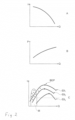
- the electronic control 6 has a further function with which the operating points are recorded at intervals of three minutes during operation of the pump unit and these are evaluated with regard to their energy efficiency, as can be seen from the Fig. 2A to C as explained below:
- the Fig. 2A shows a typical pump curve of a pump unit, where the delivery head is plotted as a function of the delivery rate.
- the delivery head is the differential pressure between the pump inlet and pump outlet, the delivery rate is the volume flow per unit of time.
- the Fig. 2A The pump curve shown schematically represents a centrifugal pump at a constant speed.
- the Fig. 2B shows the electrical power P of this pump unit as a function of the flow rate.
- the pump unit can be operated on a variety of different pump curves according to Fig. 2A and 2B driven, as shown by Fig. 2C , which shows three such curves ⁇ 1, ⁇ 2 and ⁇ 3, which represent different speeds.
- These curves represent the efficiency ⁇ as a function of the flow rate at a speed.
- the efficiency is the quotient of hydraulic power and electrical power, ideally one.
- the electrical power is determined by the input power, i.e. the product of current and voltage of the driving electric motor or motors, and is available in the form of data in the control unit 6.
- the hydraulic power results from the product of flow rate, head, density and gravitational acceleration. It can be calculated using differential pressure and flow sensors.
- the electronic control system checks the efficiency at the pump's operating points using the previously determined effectiveness curves, which are either determined during operation or are specifically approached. It can now be determined using the operating points and temporal correlation whether they are in the BEP range or outside it.
- a limit value of 30%, for example, is used as a basis, so that only It is considered how many of the operating points are outside this 30% limit and how many are inside. Those outside this limit are in Fig. 2C shown in group M.
- the electronic control 6 is thus able to check whether the pump unit can be operated in a more energy-efficient range by changing the setting parameters. If this is the case, the control 6 sends a corresponding signal to the network so that the manufacturer or operator is prompted to change the setting parameters.
- the setting parameters suitable for the pump unit can be specified by the manufacturer and transmitted wirelessly via the network to the smartphone 9 of the operator 10, who then transmits them to the electronic control 6 of the pump unit 1, or they can be selected and set by the operator himself.
- Fig. 2C the operating points are shown in a range M that lies outside the 30% of the BEPs. It is therefore shown that eight of the ten operating points lie outside the 30% range and thus 80% of the operating points fall below the specified efficiency limit range. In this case, an adjustment of the setting parameters is required.
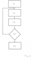
- a first step 15 the efficiency curves of the pump unit are generated. These can either be targeted or determined during operation for different flow rates depending on the speed, which is always known on the motor side and thus on the control side. Since the curves are never complete, either the pump unit can be controlled to run the entire curve or interpolated. In practice, it is sufficient to determine the BEPs that result for each speed. Once this data has been collected, the efficiency test of the pump can be carried out during operation. It goes without saying that these procedures can initially overlap in time, but this is not a problem.
- the efficiency monitoring is to be run again after a time interval of, for example, six months or one or two years after the pump has been put into operation and the first check, it starts in step 16 after the timer has expired according to the set time of six months, one or two years after the first check of the pump unit.
- the efficiency of the current operating point of the pump unit is now calculated and saved at a predetermined time interval, for example every ten minutes. After a predetermined time of, for example, 48 hours, this calculation and saving of the efficiency in the operating points is terminated in the third step 17.
- the distribution of the operating points is then evaluated on the control side with regard to their efficiency in relation to the BEP. If a predetermined percentage of the operating points, for example more than 60% of the operating points, fall below the BEP by more than 30%, a signal is emitted in the fifth step 19, depending on the evaluation result, to change the setting parameters or to replace the pump with a smaller or larger one.
- the process may only be restarted after a predetermined time interval has elapsed, so that the pump unit is monitored for efficiency virtually throughout its entire operating life. If the setting parameters are changed after the signal is given in the fifth step 19, the process is also resumed in the second step 16, whereas if the pump is replaced, the process starts again with the first step 15.
Landscapes
- Engineering & Computer Science (AREA)
- Mechanical Engineering (AREA)
- General Engineering & Computer Science (AREA)
- Control Of Non-Positive-Displacement Pumps (AREA)
- Control Of Positive-Displacement Pumps (AREA)
Abstract
Das Verfahren dient zum Betreiben eines elektronisch gesteuerten Pumpenaggregates (1), bei dem in einer elektronischen Steuerung (6) Einstellparameter der Pumpe (2) zur Anpassung an die hydraulischen Anforderungen der örtlichen Einbausituation (4, 5) einstellbar sind. Während des Betriebes des Pumpenaggregates (1) werden die Betriebsdaten registriert. Nach einer vorbestimmten Zeit wird anhand der registrierten Betriebsdaten überprüft, ob das Pumpenaggregat (1) seit der Inbetriebnahme gegenüber den werkseitigen Voreinstellungen eingestellt worden ist. Wenn dies nicht der Fall ist, wird ein Signal (11) abgeben, um auf die noch erforderliche Einstellung aufmerksam zu machen. (Fig. 1)The method is used to operate an electronically controlled pump unit (1), in which setting parameters of the pump (2) can be set in an electronic control system (6) to adapt to the hydraulic requirements of the local installation situation (4, 5). The operating data are recorded during operation of the pump unit (1). After a predetermined time, the registered operating data is used to check whether the pump unit (1) has been adjusted compared to the factory default settings since commissioning. If this is not the case, a signal (11) is emitted to draw attention to the adjustment that is still required. (Fig. 1)
Description
Die Erfindung betrifft ein Verfahren zum Betreiben eines elektronisch gesteuerten Pumpenaggregates mit den im Oberbegriff des Anspruchs 1 angegebenen Merkmalen sowie eine elektronische Steuerung eines elektromotorisch angetriebenen Kreiselpumpenaggregates mit den im Oberbegriff des Anspruchs 9 angegebenen Merkmalen.The invention relates to a method for operating an electronically controlled pump unit with the features specified in the preamble of
Moderne Pumpenaggregate, insbesondere elektromotorisch angetriebene Kreiselpumpenaggregate weisen einen Elektromotor auf, dem ein Stromrichter/Frequenzumrichter vorgeschaltet ist, so dass die Pumpen in weiten Drehzahlbereichen betrieben werden können und damit auch ein vergleichsweise großes Leistungsspektrum abdecken. Bei Umwälzpumpenaggregaten zählt es beispielsweise zum Stand der Technik, die Pumpe mit einer beliebigen konstanten Drehzahl anzutreiben, aber auch den Betrieb nach vorgegebenen Pumpenkurven zu steuern. Meist sind Regelungen vorgesehen, welche mittels hydraulischer Sensoren oder gegebenenfalls auch nur anhand der elektrischen Werte des Motors betrieben werden, so können Heizungsumwälzpumpen zum Beispiel mit Konstantdruckkurven, mit Konstant-Flow-Kurven, mit Proportionaldruckkurven oder dergleichen betrieben werden. Bei Druckerhöhungsanlagen, sogenannten Boosterpumpen, ist dabei nicht nur der Sollförderdruck einzustellen, auch die Schaltpunkte, an denen eine weitere Pumpe zugeschaltet oder abgeschaltet wird.Modern pump units, particularly centrifugal pump units driven by an electric motor, have an electric motor connected to a power converter/frequency converter so that the pumps can be operated in a wide range of speeds and thus cover a comparatively large power spectrum. In circulation pump units, for example, it is state of the art to drive the pump at any constant speed, but also to control operation according to predetermined pump curves. Usually, controls are provided which are operated using hydraulic sensors or, if necessary, only based on the electrical values of the motor. For example, heating circulation pumps can be operated with constant pressure curves, with constant flow curves, with proportional pressure curves or the like. In pressure boosting systems, so-called booster pumps, not only the target delivery pressure has to be set, but also the switching points at which another pump is switched on or off.
Diese durch die Motorelektronik ermöglichte Varianz ermöglicht zwar, ein Pumpenaggregat energetisch optimiert auf den jeweiligen Anwendungsfall zu betreiben, dies setzt jedoch voraus, dass das Pumpenaggregat auch entsprechend eingestellt worden ist, um so energetisch optimiert betrieben zu werden.This variance made possible by the motor electronics makes it possible to operate a pump unit in an energetically optimized manner for the respective application, but this requires that the pump unit has also been adjusted accordingly in order to be operated in an energetically optimized manner.
In der Praxis stellt sich jedoch häufig das Problem, dass die Pumpenaggregate eingebaut und mit den Werkseinstellungen in Betrieb genommen werden bzw. die Einstellung vorsorglich so erfolgt, dass eine Unterversorgung ausgeschlossen werden kann. So kommt es vor, dass solche an sich energetisch sehr günstig betreibbaren Pumpenaggregate über Jahre aufgrund mangelnder oder falscher Einstellung der Parameter mit schlechtem Wirkungsgrad laufen und mehr elektrische Energie benötigen, als dies an sich erforderlich wäre. Neben den erhöhten Energiekosten führt dies häufig auch dazu, dass der durch die Pumpe erzeugte Differenzdruck zu hoch ist, was zu unnötigen Leckagen im System und zu unnötig hohen Geräuschemissionen seitens der Pumpe führen kann.In practice, however, the problem often arises that the pump units are installed and put into operation with the factory settings or that the settings are made as a precautionary measure to prevent undersupply. This means that pump units that are actually very energy-efficient run for years with poor efficiency due to inadequate or incorrect setting of the parameters and require more electrical energy than is actually necessary. In addition to the increased energy costs, this often also means that the differential pressure generated by the pump is too high, which can lead to unnecessary leaks in the system and unnecessarily high noise emissions from the pump.
Vor diesem Hintergrund liegt der Erfindung die Aufgabe zugrunde, ein Verfahren zum Betreiben eines elektronisch gesteuerten Pumpenaggregates so auszubilden, dass die oben genannten Probleme nach Möglichkeit vermieden werden. Darüber hinaus soll die elektronische Steuerung eines elektromotorisch angetriebenen Kreiselpumpenaggregates zur Ausführung eines solchen Verfahrens angepasst werden.Against this background, the invention is based on the object of designing a method for operating an electronically controlled pump unit in such a way that the above-mentioned problems are avoided as far as possible. In addition, the electronic control of an electric motor-driven centrifugal pump unit is to be adapted to carry out such a method.
Der verfahrensmäßige Teil dieser Aufgabe wird durch ein Verfahren mit den in Anspruch 1 angegebenen Merkmalen gelöst, eine elektronische Steuerung zur Ausführung des erfindungsgemäßen Verfahrens ist in Anspruch 9 angegeben.The procedural part of this object is achieved by a method having the features specified in
Das erfindungsgemäße Verfahren zum Betreiben eines elektronisch gesteuerten Pumpenaggregates, bei dem in einer elektronischen Steuerung Einstellparameter der Pumpe zur Anpassung an die hydraulischen Anforderungen der örtlichen Einbausituation einstellbar sind und bei dem während des Betriebs Betriebsdaten des Pumpenaggregates registriert werden, zeichnet sich gemäß der Erfindung dadurch aus, dass nach einer vorbestimmten Zeit anhand der registrierten Betriebsdaten überprüft wird, ob das Pumpenaggregat in einem energetisch günstigeren Bereich betrieben werden kann oder aber zumindest zu überprüfen, ob alle Einstellparameter gegenüber einer Voreinstellung nicht geändert worden sind und dann, wenn festgestellt wird, dass das Pumpenaggregat in einem energetisch günstigeren Bereich betrieben werden kann oder dass die Einstellparameter gegenüber der Voreinstellung bisher nicht geändert worden sind, ein Signal zur Veränderung der Einstellparameter abgegeben wird. Das Verfahren soll vorzugsweise automatisiert, das heißt selbsttätig ablaufen, in dem es in die elektronische Steuerung implementiert wird, wie dies weiter unten noch beschrieben ist.The method according to the invention for operating an electronically controlled pump unit, in which in an electronic Control system in which the pump setting parameters can be set to adapt to the hydraulic requirements of the local installation situation and in which operating data of the pump unit is recorded during operation, is characterized according to the invention in that after a predetermined time, the recorded operating data is used to check whether the pump unit can be operated in a more energy-efficient range or at least to check whether all setting parameters have not been changed compared to a presetting and then, if it is determined that the pump unit can be operated in a more energy-efficient range or that the setting parameters have not yet been changed compared to the presetting, a signal is emitted to change the setting parameters. The method should preferably be automated, i.e. run automatically, by being implemented in the electronic control system, as described further below.
Grundgedanke der Erfindung ist es, nach einer vorbestimmten Zeit eine Überprüfung vorzunehmen, welche entweder anhand der innerhalb dieses Zeitintervalls registrierten Betriebsdaten überprüft, ob das Pumpenaggregat in einem energetisch günstigeren Bereich betrieben werden kann oder aber, wenn diese Prüfung nicht durchgeführt werden kann oder nicht zu einem eindeutigen Ergebnis führt, dass zumindest überprüft wird, ob die Einstellparameter des Pumpenaggregates gegenüber einer Voreinstellung überhaupt schon einmal geändert worden sind, um dann ein Signal abzugeben, anhand dessen erkennbar ist, dass eine Veränderung der Einstellparameter zumindest überprüft werden sollte.The basic idea of the invention is to carry out a check after a predetermined time, which either checks on the basis of the operating data recorded within this time interval whether the pump unit can be operated in a more energy-efficient range or, if this check cannot be carried out or does not lead to a clear result, at least checks whether the setting parameters of the pump unit have ever been changed compared to a presetting, in order to then emit a signal on the basis of which it can be recognized that a change in the setting parameters should at least be checked.
Pumpenaggregat im Sinne der Erfindung kann dabei grundsätzlich jede elektromotorisch angetriebene Pumpe mit einer elektronischen Steuerung sein, bei welcher die Einstellparametern der Pumpe zur Anpassung an die hydraulischen Anforderungen der örtlichen Einbausituation veränderbar sind. Typischerweise handelt es sich hierbei um mittels Stromrichters/Frequenzumrichters gesteuerte ein- oder mehrstufige Kreiselpumpen. Pumpenaggregat im Sinne der Erfindung kann jedoch auch eine Anzahl von Einzelpumpenaggregaten sein, welche durch eine gemeinsame Steuerung betrieben werden, wie dies beispielsweise bei Druckerhöhungsanlagen (z.B. Boosterpumpen) der Fall ist.In principle, a pump unit within the meaning of the invention can be any electric motor-driven pump with an electronic control system in which the setting parameters of the pump can be adapted to the hydraulic requirements of the local installation situation. are changeable. Typically, these are single- or multi-stage centrifugal pumps controlled by means of a power converter/frequency converter. However, a pump unit in the sense of the invention can also be a number of individual pump units which are operated by a common control system, as is the case with pressure boosting systems (eg booster pumps).
Das abgegebene Signal kann beispielsweise zur Ansteuerung einer am Pumpenaggregat vorgesehenen Kontrollleuchte, zur Abgabe eines akustischen Alarms oder auch zur Übermittlung eines entsprechenden Datensatzes an eine cloudbasierte Datenbank oder einen Server des Herstellers und/oder Betreibers des Pumpenaggregates gebildet sein.The signal emitted can, for example, be used to control an indicator light provided on the pump unit, to emit an acoustic alarm or to transmit a corresponding data set to a cloud-based database or a server of the manufacturer and/or operator of the pump unit.
Das erfindungsgemäße Verfahren wird zweckmäßigerweise mit Installation des Pumpenaggregates gestartet, dann ist die werkseitige Voreinstellung des Pumpenaggregates die Voreinstellung. Dann wird also nach einer vorbestimmten Zeit überprüft, ob diese werkseitige Voreinstellung geändert worden ist oder nicht und im Falle einer Nichtänderung das entsprechende Signal abgegeben.The method according to the invention is expediently started with the installation of the pump unit, in which case the factory presetting of the pump unit is the default setting. Then, after a predetermined time, a check is made as to whether this factory presetting has been changed or not and, if there has been no change, the corresponding signal is emitted.
Insoweit günstiger ist es, wenn nach einer vorbestimmten Zeit anhand der registrierten Betriebsdaten überprüft wird, ob das Pumpenaggregat in einem energetisch günstigeren Bereich betrieben werden kann. Hierzu ist in einer Weiterbildung des erfindungsgemäßen Verfahrens vorgesehen, dass für die energetische Auswertung der Betriebsdaten elektrische Betriebsdaten des Motors, insbesondere die elektrische Leistung des Motors, die steuerungsseitig ohnehin zur Verfügung stehen und andererseits hydraulische Betriebsdaten der Pumpe, insbesondere der Druck- und/oder Durchfluss verwendet werden. Hierdurch ist es ohne weitere Daten möglich, das energetische Verhalten des Pumpenaggregates zu analysieren. Dabei wird die sich aus den hydraulischen Betriebsdaten ergebende hydraulische Leistung mit der elektrischen Leistung des Motors ins Verhältnis gesetzt um hierdurch die Effizienz des Aggregates zu ermitteln. Die Leistung des Elektromotors steht seitens der Steuerungselektronik zur Verfügung, von den hydraulischen Daten steht in der Regel ein Druck, typischerweise der von der Pumpe aufgebrachte Differenzdruck sensorisch zur Verfügung, so dass in Verbindung mit der motorseitig ebenfalls zur Verfügung stehenden Drehzahl die hydraulische Leistung bestimmt werden kann. Alternativ oder zusätzlich können die Daten eines Durchflusssensors hierzu verwendet werden. Die hydraulische Leistung ergibt sich bekanntermaßen aus dem Produkt von Differenzdruck, Durchflussmenge, der Dichte des Fördermediums und der Gravitationsbeschleunigung. So kann also mit diesen Daten zeitlich punktuell oder auch kontinuierlich die Effizienz des Pumpenaggregates durch energetische Auswertung der Betriebsdaten ermittelt werden.In this respect, it is more advantageous if, after a predetermined time, the registered operating data is used to check whether the pump unit can be operated in a more energy-efficient range. For this purpose, a further development of the method according to the invention provides that, for the energy evaluation of the operating data, electrical operating data of the motor, in particular the electrical power of the motor, which is already available on the control side, and hydraulic operating data of the pump, in particular the pressure and/or flow, are used. This makes it possible to determine the energy behavior of the pump unit without any additional data. to analyze. The hydraulic power resulting from the hydraulic operating data is compared with the electrical power of the motor in order to determine the efficiency of the unit. The power of the electric motor is available from the control electronics, and from the hydraulic data a pressure, typically the differential pressure applied by the pump, is usually available via a sensor, so that the hydraulic power can be determined in conjunction with the speed also available on the motor side. Alternatively or additionally, the data from a flow sensor can be used for this purpose. The hydraulic power is known to be the product of differential pressure, flow rate, the density of the pumped medium and the gravitational acceleration. This data can therefore be used to determine the efficiency of the pump unit at specific times or continuously by evaluating the energy from the operating data.
Vorteilhaft werden die Betriebsdaten in zeitlichen Abständen oder kontinuierlich registriert, das heißt erfasst und gespeichert, um nach der vorbestimmten Zeit eine Effizienzprüfung durchführen zu können. Dabei ist es zweckmäßig, eine solche Effizienzprüfung nicht nur von der Erstinbetriebnahme an durchzuführen, sondern in regelmäßigen zeitlichen Abständen. Um die zu registrierende Datenmenge möglichst klein zu halten, ist es dabei sinnvoll, Grenzwerte festzusetzen, wobei lediglich ein Unter- und Überschreiten dieser Grenzwerte zu registrieren ist bzw. der zeitliche Verlauf des Unter- und Überschreitens. Für die Effizienzermittlung kann beispielsweise festgelegt werden, dass das Pumpenaggregat alle sechs Minuten seine Effizienz, also das Verhältnis zwischen hydraulischer Leistung und elektrischer Leistung ermittelt. Wenn der Grenzwert auf maximal 30% festgelegt worden ist, dann sind nur die Betriebspunkte zu registrieren, bei welchen der Effizienzfaktor kleiner 0,7 ist. Die Anzahl der insgesamt zu berücksichtigenden Betriebspunkte ergibt sich dann durch die vorbestimmte Zeit dividiert durch sechs Minuten. Das erfindungsgemäße Verfahren kann nicht nur dazu verwendet werden, einen energetisch günstigen Betrieb des Pumpenaggregates zu forcieren, sondern kann auch dazu verwendet werden, eine deutliche Unter- oder Überdimensionierung des Pumpenaggregates zu ermitteln und anzuzeigen.The operating data are advantageously recorded at intervals or continuously, i.e. recorded and stored, in order to be able to carry out an efficiency test after the predetermined time. It is expedient to carry out such an efficiency test not only from the initial commissioning, but at regular intervals. In order to keep the amount of data to be recorded as small as possible, it is sensible to set limit values, whereby only if these limit values are exceeded or undershot, or the time course of the undershoot or overshoot, is to be recorded. For example, to determine efficiency, it can be specified that the pump unit determines its efficiency, i.e. the ratio between hydraulic power and electrical power, every six minutes. If the limit value has been set at a maximum of 30%, then only the operating points are to be recorded where the efficiency factor is less than 0.7. The total number of operating points to be taken into account is then calculated by dividing the predetermined time by six minutes. The inventive The method can not only be used to force an energy-efficient operation of the pump unit, but can also be used to determine and indicate a significant under- or over-dimensioning of the pump unit.
Das erfindungsgemäße Verfahren kann insbesondere bei einer Internetanbindung des Pumpenaggregates im Idealfall zu einer automatischen Anpassung der Einstellparameter des Pumpenaggregates führen, wenn über ein internetbasiertes Netzwerk nicht nur die Übermittlung und Registrierung der Betriebsdaten des Pumpenaggregates erfolgt, sondern nach netzwerkseitiger Überprüfung eine entsprechende Anpassung der Einstellparameter initiiert werden kann. Dies setzt allerdings nicht nur eine Datenanbindung des Pumpenaggregates an das internetbasierte Netzwerk, sondern auch die Möglichkeit der Veränderung der Betriebsparameter über dieses Netzwerk voraus.The method according to the invention can ideally lead to an automatic adjustment of the setting parameters of the pump unit, particularly when the pump unit is connected to the Internet, if not only the transmission and registration of the operating data of the pump unit takes place via an Internet-based network, but also a corresponding adjustment of the setting parameters can be initiated after a network-side check. However, this requires not only a data connection of the pump unit to the Internet-based network, but also the possibility of changing the operating parameters via this network.
Bei Pumpenaggregaten, die eine solche internetbasierte Einstellung über ein Netzwerk nicht vorsehen, kann netzwerkseitig ein Datensatz mit entsprechend angepassten Einstellparametern zum Download bereitgestellt werden, welche der Servicetechniker beispielsweise auf sein Smartphone herunterlädt und dann vor Ort in die elektronische Motorsteuerung einliest. Idealerweise wird das Verfahren, bei welchem die Effizienz des Pumpenaggregates überprüft wird, kontinuierlich während der gesamten Betriebszeit durchgeführt. Im Hinblick auf die dann zu registrierende und verarbeitende große Datenmenge wird es jedoch in der Praxis zweckmäßig sein, nach Erstinbetriebnahme innerhalb relativ kurzer Zeit zu überprüfen, ob das Pumpenaggregat energetisch günstig läuft und dies dann später in größeren Zeitabständen zu überprüfen. Insoweit ist es vorteilhaft, die vorbestimmte Zeit, in welcher die Registrierung der Betriebsdaten erfolgt, zwischen einer Stunde und sieben Tagen zu wählen. Wenn das Pumpenaggregat dann erst einmal in einen energetisch günstigeren Zustand versetzt worden ist und sich die hydraulischen Randbedingungen, wie dies häufig der Fall ist, nicht mehr grundlegend ändern, dann kann es ausreichen die Energieeffizienzprüfung nach Ablauf eines Zeitintervalls wiederholt wird. Ein solches Zeitintervall liegt typischerweise zwischen sechs Monaten und fünf Jahren, kann jedoch auch im Einzelfall kürzer gewählt werden.For pump units that do not provide for such internet-based setting via a network, a data set with appropriately adjusted setting parameters can be made available for download on the network side, which the service technician can download to his smartphone, for example, and then read into the electronic motor control on site. Ideally, the process in which the efficiency of the pump unit is checked is carried out continuously during the entire operating time. In view of the large amount of data that then has to be recorded and processed, it will be useful in practice to check within a relatively short time after initial commissioning whether the pump unit is running efficiently in terms of energy and then to check this later at longer intervals. In this respect, it is advantageous to choose the predetermined time in which the operating data is recorded between one hour and seven days. Once the pump unit has been put into an energetically efficient mode, more favourable condition and the hydraulic boundary conditions no longer change fundamentally, as is often the case, then it may be sufficient to repeat the energy efficiency test after a certain period of time. Such a period of time is typically between six months and five years, but can also be shorter in individual cases.
Das erfindungsgemäße Verfahren kann bei vorhandenen Pumpenaggregaten typischerweise durch ein Softwareupdate in die elektronische Motorsteuerung implementiert werden. Allerdings ist dann die Signalausgabe an die hardwaremäßig vorgegebenen Möglichkeiten des Pumpenaggregates gebunden. In einfachster Form wird daher, wenn das Pumpenaggregat keine Netzwerkanbindung, insbesondere keinen Internetzugang hat, eine Anzeige, zum Beispiel eine rote Kontrollleuchte oder ein gelbes Blinklicht aktiviert und alternativ oder zusätzlich ein akustisches Signal abgeben, so dass jeder, der in der Nähe des Pumpenaggregates ist, darauf aufmerksam wird, dass hier offensichtlich ein Handlungsbedarf besteht. Wenn, was bei einer Vielzahl insbesondere größerer Pumpenaggregate heute schon der Fall ist, eine Netzwerkanbindung besteht, dann ist es vorteilhaft, wenn das Signal in Form eines Datenpaketes über das internetbasierte Netzwerk zu einem Server übertragen wird, welcher den Hersteller oder die Wartungsfirma darauf hinweist, dass hier Handlungsbedarf besteht. In diesem Falle ist es vorteilhaft, wenn das Datenpaket die Standortdaten des Pumpenaggregates beinhaltet, da dann eine räumliche Zuordnung ohne Zugriff auf weitere personenbezogene Datenbanken möglich ist.The method according to the invention can typically be implemented in existing pump units by means of a software update in the electronic motor control. However, the signal output is then tied to the hardware capabilities of the pump unit. In the simplest form, if the pump unit has no network connection, in particular no internet access, a display, for example a red indicator light or a yellow flashing light, is activated and alternatively or additionally an acoustic signal is emitted so that everyone who is near the pump unit is aware that there is obviously a need for action. If there is a network connection, which is already the case with a large number of pump units, in particular larger ones, then it is advantageous if the signal is transmitted in the form of a data packet via the internet-based network to a server, which informs the manufacturer or the maintenance company that there is a need for action. In this case, it is advantageous if the data packet contains the location data of the pump unit, as spatial assignment is then possible without access to other personal databases.
Zur Ausführung des erfindungsgemäßen Verfahrens dient die erfindungsgemäße elektronische Steuerung eines elektromotorisch angetriebenen Kreiselpumpenaggregates. Sie weist Mittel zum Einstellen von Einstellparametern zur Anpassung des Pumpenaggregates an die hydraulischen Anforderungen der örtlichen Einbausituation auf. Diese können durch Taster/Schalter/Touchscreen am Aggregat selbst gebildet sein, mit denen die Einstellparameter geändert werden können, beispielsweise durch Auswahl entsprechender Regelkurven oder Druck/Flow-Sollwerte. Solche Mittel können jedoch auch drahtlos, beispielsweise mittels eines mobilen Computers, typischerweise Smartphones oder Tablets gebildet sein, auf denen eine entsprechende Softwareapplikation läuft, mit der diese Daten eingegeben und drahtlos an die elektronische Steuerung übertragen werden können. Diese Mittel können bei Netzwerkanbindung der elektronischen Steuerung auch durch Übermittlung entsprechender Einstellungen über das Netzwerk gebildet sein.The electronic control of an electric motor-driven centrifugal pump unit according to the invention is used to carry out the method according to the invention. It has means for setting setting parameters to adapt the pump unit to the hydraulic requirements of the local installation situation. These can by buttons/switches/touch screens on the unit itself, with which the setting parameters can be changed, for example by selecting corresponding control curves or pressure/flow setpoints. However, such means can also be formed wirelessly, for example by means of a mobile computer, typically smartphones or tablets, on which a corresponding software application runs with which this data can be entered and transmitted wirelessly to the electronic control system. If the electronic control system is connected to a network, these means can also be formed by transmitting corresponding settings over the network.
Die Steuerung selbst ist dazu ausgebildet, Betriebsdaten des Pumpenaggregates zu registrieren oder weiterzuleiten. Je nach zur Verfügung stehender Speicher- und Rechenkapazität kann das erfindungsgemäße Verfahren einschließlich Registrierung und Auswertung der registrierten Daten innerhalb der elektronischen Steuerung des Pumpenaggregates oder zumindest teilweise auch über einen netzwerkgebundenen Server erfolgen, mit der die elektronische Steuerung in Datenverbindung steht.The control itself is designed to register or forward operating data of the pump unit. Depending on the available storage and computing capacity, the method according to the invention, including registration and evaluation of the registered data, can be carried out within the electronic control of the pump unit or at least partially via a network-connected server with which the electronic control is in data connection.
Gemäß der Erfindung ist die elektronische Steuerung des Pumpenaggregates allerdings so ausgebildet, um selbst zu ermitteln, ob eine Einstellung der Einstellparameter gegenüber einer registrierten Einstellung nach einer vorbestimmten Zeit erfolgt ist und bei nicht erfolgter Einstellung selbsttätig ein Signal abzugeben. Grundsätzlich kann eine solche Überprüfung in regelmäßigen Abständen selbsttätig durch die Steuerung erfolgen oder auch ständig. Besonderes vorteilhaft ist es jedoch, wenn diese vorbestimmte Zeit erstmals von der Inbetriebnahme der Steuerung an läuft und die registrierte Einstellung die werkseitige Einstellung ist. Damit ist sichergestellt, dass dann, wenn das Pumpenaggregat nach Auslieferung durch den Hersteller an seinem Bestimmungsort eingebaut und an das elektrische Versorgungsnetz angeschlossen ist, unmittelbar nach dieser Erstinbetriebnahme zumindest überwacht wird, ob die Einstellparameter gegenüber den werkseitigen Einstellungen verändert worden sind oder nicht. Wenn letzteres nicht der Fall ist und das zur Einstellung der Einstellparameter auffordernde Signal abgegeben wird, ist mit hoher Wahrscheinlichkeit davon auszugehen, dass das Pumpenaggregat in einem energetisch nicht optimierten Bereich läuft, da nämlich nach Einbau und Inbetriebnahme keinerlei Einstellung der Einstellparameter erfolgt ist.According to the invention, the electronic control of the pump unit is designed to determine itself whether a setting of the setting parameters has been made after a predetermined time compared to a registered setting and to automatically emit a signal if the setting has not been made. In principle, such a check can be carried out automatically by the control at regular intervals or even continuously. However, it is particularly advantageous if this predetermined time begins when the control is put into operation and the registered setting is the factory setting. This ensures that when the pump unit is installed at its destination after delivery by the manufacturer and connected to the electrical supply network, immediately after During this initial commissioning, it is at least monitored whether the setting parameters have been changed compared to the factory settings or not. If this is not the case and the signal requesting the setting parameters to be adjusted is given, it can be assumed with a high degree of probability that the pump unit is running in an energy-optimized range, since no setting of the setting parameters has been made after installation and commissioning.
In vorteilhafter Weiterbildung ist jedoch die elektronische Steuerung weiter dazu ausgebildet, um selbsttätig zu ermitteln, ob das Pumpenaggregat in einem energetisch günstigen Bereich betrieben wird oder nicht. Die insoweit erforderlichen Speicher- und Rechenoperationen sind allerdings aufwendiger, weshalb diese vorteilhaft auch über ein Netzwerk extern erfolgen können. Hierzu, als auch zur Übermittlung des Signals und/oder von Betriebsdaten, weist die Steuerung vorteilhaft eine Schnittstelle zu einem Netzwerk auf, vorzugsweise zu einem internetbasierten Netzwerk. Eine solche Schnittstelle kann drahtgebunden, beispielsweise als LAN-Anschluss ausgebildet sein, ist aber besonders vorteilhaft zur drahtlosen Datenübertragung ausgelegt, beispielsweise mittels WLAN oder Mobilfunkanbindung.In an advantageous further development, however, the electronic control is further designed to automatically determine whether the pump unit is being operated in an energy-efficient range or not. The storage and computing operations required in this regard are more complex, however, which is why they can advantageously also be carried out externally via a network. For this purpose, as well as for transmitting the signal and/or operating data, the control advantageously has an interface to a network, preferably to an internet-based network. Such an interface can be wired, for example as a LAN connection, but is particularly advantageously designed for wireless data transmission, for example via WLAN or a mobile phone connection.
Da Pumpenaggregate häufig an durch Funknetzwerke nicht abgedeckte Bereiche - sei es unterirdisch oder in Kellern - angeordnet sind, kann es gemäß einer erfindungsgemäßen Weiterbildung vorteilhaft sein, die elektronische Steuerung so auszulegen, dass sie zur Übertragung der Einstellparameter mittels einer Softwareapplikation eines mobilen Eingabegerätes, insbesondere eines Smartphones vorgesehen ist. Dabei kann das mobile Eingabegerät die Verbindung zum Netzwerk herstellen, was gegebenenfalls ja nicht zeitgleich erfolgen muss. Dann werden die zur übertragenden Einstellparameter vorteilhaft aus dem Netzwerk mittels des mobilen Eingabegerätes geladen und nachfolgend in die elektronische Steuerung übertragen.Since pump units are often located in areas not covered by wireless networks - whether underground or in basements - it can be advantageous according to a further development of the invention to design the electronic control in such a way that it is provided for transmitting the setting parameters using a software application of a mobile input device, in particular a smartphone. The mobile input device can establish the connection to the network, which may not have to happen at the same time. The setting parameters to be transmitted are then advantageously taken from the network using of the mobile input device and subsequently transferred to the electronic control system.
Um das erfindungsgemäße Verfahren mit möglichst geringem hardwaremäßigem Aufwand in einer elektronischen Steuerung realisieren zu können, ist gemäß einer Weiterbildung der Erfindung vorgesehen, dass die Einstellparameter in einer Datei der Steuerung gespeichert sind, und dass lediglich die Änderung dieser Datei überwacht wird. Datei im Sinne dieser Erfindung kann auch eine Gruppe von Dateien oder ein Ordner sein, entscheidend ist, dass die Überwachung ohne konkrete Überwachung der Einstellparameter selbst erfolgen kann, sondern in einfacher Weise durch die Überwachung der Datei, welche, bei Veränderung ein geändertes Datum oder ein anderes Kennzeichen aufweist.In order to be able to implement the method according to the invention with the least possible hardware outlay in an electronic control system, a further development of the invention provides that the setting parameters are stored in a file in the control system and that only the change in this file is monitored. A file in the sense of this invention can also be a group of files or a folder; the crucial point is that the monitoring can take place without specifically monitoring the setting parameters themselves, but simply by monitoring the file, which, when changed, has a changed date or another identifier.
Die Einstellparameterderelektronischen Steuerung sind vorteilhaft eine oder mehrere der Regelgrößen wie Fördermenge, Förderdruck, Drehzahl, Leistung wobei die hydraulischen Regelgrößen Fördermenge und/oder Förderdruck typischerweise in Form von Regelkurven einstellbar sind.The setting parameters of the electronic control are advantageously one or more of the control variables such as flow rate, delivery pressure, speed, power, whereby the hydraulic control variables flow rate and/or delivery pressure can typically be set in the form of control curves.
Die Erfindung ist nachfolgend anhand von in den Zeichnungen dargestellten Ausführungsbeispielen näher erläutert. Es zeigen:
- Fig. 1
- in schematischer Darstellung eine cloudbasierte Einbindung einer elektronischen Motorsteuerung eines Pumpenaggregates,
- Fig. 2A bis C
- drei Diagramme mit Pumpenkurven und
- Fig. 3
- ein Ablaufdiagramm.
- Fig.1
- a schematic representation of a cloud-based integration of an electronic motor control of a pump unit,
- Fig. 2A to C
- three diagrams with pump curves and
- Fig.3
- a flow chart.
In
Die elektronische Steuerung 6 ist dazu ausgelegt, nach einer vorbestimmten Zeit nach Aufnahme des Betriebs des Pumpenaggregates 1 zu überprüfen, ob die Einstellparameter gegenüber den Werkseinstellungen geändert worden sind. Diese Parameter sind in einer Datei der Steuerung 6 digital abgespeichert, die Steuerung 6 überwacht das Speicherdatum der Datei. Von der Erstinbetriebnahme an läuft ein Timer, der z.B. auf 72 Stunden eingestellt ist, so dass nach Ablauf dieser vorbestimmten Zeit überprüft wird, ob sich das Speicherdatum der Datei geändert hat oder nicht. Ist dies nicht der Fall, wird ein Signal abgegeben, und zwar an der Steuerung 6 selbst zur Aktivierung einer Warnleuchte 11, welche ein blinkendes Signal abgibt als Zeichen dafür, dass das Pumpenaggregat 1 noch nicht eingestellt worden ist. Gleichzeitig wird ein entsprechendes Datensignal an das Netz abgegeben, so dass in der Datenbank des Herstellers 7 unter Angabe der GPS-Daten des Standortes des Pumpenaggregates dies vermerkt wird und gleichzeitig ein Hinweis erscheint, dass dieses Pumpenaggregat von einem Servicetechniker einzustellen ist. Je nach Ausgestaltung und Anbindung an das Netzwerks, kann diese erforderliche Einstellung über das Netzwerk selbst oder über den Hersteller 7 oder Betreiber erfolgen. In dem dargestellten Ausführungsbeispiel ist ein Servicetechniker erforderlich, also ein Bediener 10, der sich mit seinem Smartphone 9 und einer darauf laufenden Softwareapplikation zum Pumpenaggregat 1 begibt, um über sein Smartphone 9 die Einstellparameter in der Steuerung 6 entsprechend anzupassen. Der Servicetechniker 10 erhält dabei über das Netzwerk 8 nicht nur den Hinweis, dass das Pumpenaggregat 1 hinsichtlich seiner Einstellparameter zu konfigurieren ist, sondern auch die Standortdaten und, soweit vorhanden, die aus dem Netzwerk 8 herunterladbaren Daten zur Anpassung der Einstellparameter.The electronic control 6 is designed to check after a predetermined time after the
Die elektronische Steuerung 6 weist neben dieser Einrichtung zur Überwachung der Einstellung der Einstellparameter eine weitere Funktion auf, mit der während des Betriebs des Pumpenaggregates in zeitlichen Abständen von drei Minuten die Betriebspunkte erfasst und diese hinsichtlich ihrer energetischen Effizienz ausgewertet werden, wie dies anhand der
Die
Bei Einsatz eines Stromrichters/Frequenzumrichters mit elektronischer Steuerung 6 kann das Pumpenaggregat auf einer Vielzahl unterschiedlicher solcher Pumpenkurven gemäß
Diese Effizienzberechnungen werden in der elektronischen Steuerung 6 in zeitlichen Abständen von z.B. drei Minuten durchgeführt und gespeichert. Die entsprechenden Betriebspunkte sind in
Die elektronische Steuerung überprüft nun nach einer vorbestimmten Zeit die Effizienz in den Betriebspunkten der Pumpe anhand der zuvor ermittelten Effektivitätskurven, die entweder im laufenden Betrieb ermittelt oder gezielt angefahren werden. Es kann nun anhand der Betriebspunkte unter zeitlicher Korrelation festgestellt werden, ob diese im Bereich der BEP's liegen oder außerhalb. Dabei wird zweckmäßigerweise ein Grenzwert von beispielsweise 30% zugrunde gelegt, so dass lediglich betrachtet wird, wie viele der Betriebspunkte außerhalb dieser 30% Grenze liegen und wie viele innerhalb. Die außerhalb dieser Grenze liegenden sind in
Die elektronische Steuerung 6 ist somit in der Lage zu überprüfen, ob durch Änderung der Einstellparameter das Pumpenaggregat in einem energetisch effektiveren Bereich gefahren werden kann. Wenn dies der Fall ist, gibt die Steuerung 6 ein entsprechendes Signal an das Netzwerk ab, so dass hersteller- oder betreiberseitig eine Aufforderung zur Änderung der Einstellparameter ergeht.The electronic control 6 is thus able to check whether the pump unit can be operated in a more energy-efficient range by changing the setting parameters. If this is the case, the control 6 sends a corresponding signal to the network so that the manufacturer or operator is prompted to change the setting parameters.
Dabei können die für das Pumpenaggregat geeigneten Einstellparameter herstellerseitig vorgegeben sein und über das Netzwerk drahtlos an das Smartphone 9 des Bedieners 10 übertragen werden, der diese dann in die elektronische Steuerung 6 des Pumpenaggregates 1 überträgt oder auch von dem Bediener selbst gewählt und eingestellt werden.The setting parameters suitable for the pump unit can be specified by the manufacturer and transmitted wirelessly via the network to the smartphone 9 of the
In
Anhand von
Wenn nun nach einem Zeitintervall von beispielsweise sechs Monaten oder ein oder zwei Jahren nach Inbetriebnahme der Pumpe und erster Überprüfung die Effizienzüberwachung erneut ablaufen soll, beginnt diese im Schritt 16 nach Ablauf des Timers entsprechend der eingestellten Zeit von sechs Monaten, ein oder zwei Jahren nach der Erstüberprüfung des Pumpenaggregates.If the efficiency monitoring is to be run again after a time interval of, for example, six months or one or two years after the pump has been put into operation and the first check, it starts in
Es wird nun in einem zuvor bestimmten zeitlichen Abstand der beispielsweise zehn Minuten beträgt die Effizienz des aktuellen Betriebspunktes des Pumpenaggregates berechnet und gespeichert. Nach Ablauf einer vorbestimmten Zeit von beispielsweise 48 Stunden wird diese Berechnung und Speicherung der Effizienz in den Betriebspunkten im dritten Schritt 17 beendet. Im vierten Schritt 18 wird dann steuerungsseitig die Verteilung der Betriebspunkte im Hinblick auf ihre Effizienz jeweils bezogen auf den BEP ausgewertet. Wenn ein vorbestimmter Prozentsatz der Betriebspunkte, beispielsweise mehr als 60% der Betriebspunkte den BEP jeweils um mehr als 30% unterschreitet, so wird im fünften Schritt 19 ein Signal abgegeben, je nach Auswertergebnis, um die Einstellparameter zu ändern oder auch die Pumpe durch eine kleinere oder größere zu ersetzen.The efficiency of the current operating point of the pump unit is now calculated and saved at a predetermined time interval, for example every ten minutes. After a predetermined time of, for example, 48 hours, this calculation and saving of the efficiency in the operating points is terminated in the
Wird steuerungsseitig ermittelt, dass die Betriebspunkte hinsichtlich ihrer Effizienz innerhalb der zuvor festgelegten 30%-Grenze liegen, dann wird das Verfahren gegebenenfalls auch erst nach Ablauf eines vorbestimmten Zeitintervalls erneut gestartet, so dass das Pumpenaggregat quasi über seine gesamte Betriebsdauer hinweg effizienzüberwacht ist. Wenn nach Signalabgabe im fünften Schritt 19 die Einstellparameter geändert werden, wird ebenfalls das Verfahren im zweiten Schritt 16 wieder aufgenommen, wohingegen beim Austausch der Pumpe das Verfahren mit dem ersten Schritt 15 wieder beginnt.If the control system determines that the operating points are within the previously defined 30% limit in terms of their efficiency, the process may only be restarted after a predetermined time interval has elapsed, so that the pump unit is monitored for efficiency virtually throughout its entire operating life. If the setting parameters are changed after the signal is given in the
- 11
- PumpenaggregatPump unit
- 22
- KreiselpumpeCentrifugal pump
- 33
- ElektromotorElectric motor
- 44
- SaugleitungSuction line
- 55
- DruckleitungPressure line
- 66
- elektronische Steuerungelectronic control
- 77
- Hersteller/BetreiberManufacturer/Operator
- 88th
- Internet/CloudInternet/Cloud
- 99
- Smartphonesmartphones
- 1010
- Bedieneroperator
- 1111
- WarnleuchteWarning light
- 1515
- erster Schritt (Ermitteln der Effizienzkurven für unterschiedliche Drehzahlen)First step (determining the efficiency curves for different speeds)
- 1616
- zweiter Schritt (Starten des Programms und Starten des Timers sechs Monate, ein, zwei Jahre)second step (starting the program and starting the timer six months, one, two years)
- 1717
- dritter Schritt (Speichern und Ermitteln der Effizienz von Betriebspunkten)third step (saving and determining the efficiency of operating points)
- 1818
- vierter Schritt (Auswerten der ermittelten Effizienzwerte)fourth step (evaluation of the determined efficiency values)
- 1919
- fünfter Schritt (Signalabgabe)fifth step (signal delivery)
Claims (13)
Priority Applications (1)
| Application Number | Priority Date | Filing Date | Title |
|---|---|---|---|
| EP24165496.1A EP4365453A2 (en) | 2016-12-30 | 2016-12-30 | Method for operating an electronically controlled pump unit |
Applications Claiming Priority (2)
| Application Number | Priority Date | Filing Date | Title |
|---|---|---|---|
| EP16207574.1A EP3242033B1 (en) | 2016-12-30 | 2016-12-30 | Method for operating an electronically controlled pump unit |
| EP24165496.1A EP4365453A2 (en) | 2016-12-30 | 2016-12-30 | Method for operating an electronically controlled pump unit |
Related Parent Applications (2)
| Application Number | Title | Priority Date | Filing Date |
|---|---|---|---|
| EP16207574.1A Division-Into EP3242033B1 (en) | 2016-12-30 | 2016-12-30 | Method for operating an electronically controlled pump unit |
| EP16207574.1A Division EP3242033B1 (en) | 2016-12-30 | 2016-12-30 | Method for operating an electronically controlled pump unit |
Publications (1)
| Publication Number | Publication Date |
|---|---|
| EP4365453A2 true EP4365453A2 (en) | 2024-05-08 |
Family
ID=57680165
Family Applications (2)
| Application Number | Title | Priority Date | Filing Date |
|---|---|---|---|
| EP24165496.1A Pending EP4365453A2 (en) | 2016-12-30 | 2016-12-30 | Method for operating an electronically controlled pump unit |
| EP16207574.1A Active EP3242033B1 (en) | 2016-12-30 | 2016-12-30 | Method for operating an electronically controlled pump unit |
Family Applications After (1)
| Application Number | Title | Priority Date | Filing Date |
|---|---|---|---|
| EP16207574.1A Active EP3242033B1 (en) | 2016-12-30 | 2016-12-30 | Method for operating an electronically controlled pump unit |
Country Status (4)
| Country | Link |
|---|---|
| US (2) | US11566625B2 (en) |
| EP (2) | EP4365453A2 (en) |
| CN (2) | CN110139990B (en) |
| WO (1) | WO2018122025A1 (en) |
Families Citing this family (5)
| Publication number | Priority date | Publication date | Assignee | Title |
|---|---|---|---|---|
| EP3483449B1 (en) * | 2017-11-13 | 2023-11-08 | Wilo Se | Method for monitoring an electronically controlled centrifugal pump |
| WO2019096545A1 (en) * | 2017-11-15 | 2019-05-23 | KSB SE & Co. KGaA | Method and apparatus for protecting pump units from cyber attacks |
| IT201800003117A1 (en) * | 2018-02-28 | 2019-08-28 | Dab Pumps Spa | ASSEMBLY OF CENTRIFUGAL ELECTRIC PUMP WITH IMPROVED USER INTERFACE DEVICE |
| CN110939560B (en) | 2019-11-04 | 2021-09-14 | 姚福来 | Method for determining electricity-saving optimization operation and switching point of water pump unit |
| US11441973B2 (en) | 2020-02-21 | 2022-09-13 | Hamilton Sundstrand Corporation | Pump health monitoring |
Family Cites Families (27)
| Publication number | Priority date | Publication date | Assignee | Title |
|---|---|---|---|---|
| DE19618462A1 (en) * | 1996-05-08 | 1997-11-13 | Status Pro Maschinenmesstechni | Extrinsic power parameter determination method for energy conversion appliance |
| US6260004B1 (en) * | 1997-12-31 | 2001-07-10 | Innovation Management Group, Inc. | Method and apparatus for diagnosing a pump system |
| US6655922B1 (en) * | 2001-08-10 | 2003-12-02 | Rockwell Automation Technologies, Inc. | System and method for detecting and diagnosing pump cavitation |
| CN100362448C (en) * | 2003-02-26 | 2008-01-16 | 华为技术有限公司 | Method for monitoring run of fan |
| US7634328B2 (en) * | 2004-01-20 | 2009-12-15 | Masoud Medizade | Method, system and computer program product for monitoring and optimizing fluid extraction from geologic strata |
| DE502004006565D1 (en) * | 2004-02-11 | 2008-04-30 | Grundfos As | Method for determining errors in the operation of a pump unit |
| EP1614903B1 (en) * | 2004-07-07 | 2019-05-22 | Grundfos A/S | Driving unit for a centrifugal pump |
| US7686589B2 (en) * | 2004-08-26 | 2010-03-30 | Pentair Water Pool And Spa, Inc. | Pumping system with power optimization |
| US7854597B2 (en) * | 2004-08-26 | 2010-12-21 | Pentair Water Pool And Spa, Inc. | Pumping system with two way communication |
| DE102005006410A1 (en) * | 2005-02-11 | 2006-08-17 | Siemens Ag | Method for optimizing the operation of several compressor units and apparatus for this purpose |
| EP2039939B2 (en) * | 2007-09-20 | 2020-11-18 | Grundfos Management A/S | Method for monitoring an energy conversion device |
| DE102009022107A1 (en) * | 2009-05-20 | 2010-11-25 | Ksb Ag | Method and device for determining the operating point of a work machine |
| US9181953B2 (en) * | 2009-10-01 | 2015-11-10 | Specific Energy | Controlling pumps for improved energy efficiency |
| US9341178B1 (en) * | 2010-07-26 | 2016-05-17 | Lincoln Williams | Energy optimization for variable speed pumps |
| KR20120132776A (en) * | 2011-05-30 | 2012-12-10 | 주식회사 협성히스코 | Pump scheduling method using thermodynamics pump efficiency measuring and system of the same |
| EP2573403B1 (en) * | 2011-09-20 | 2017-12-06 | Grundfos Holding A/S | Pump |
| CA2856280C (en) * | 2011-11-18 | 2020-01-28 | Cooper Technologies Company | Improved efficiency heating, ventilating, and air conditioning through indirect extension of compressor run times |
| DE102011120686A1 (en) * | 2011-12-09 | 2013-06-13 | Daimler Ag | Method for monitoring a pump |
| US20130204546A1 (en) * | 2012-02-02 | 2013-08-08 | Ghd Pty Ltd. | On-line pump efficiency determining system and related method for determining pump efficiency |
| KR101311715B1 (en) * | 2012-06-22 | 2013-09-25 | 한국농어촌공사 | Water supply system and its control method |
| US20150122037A1 (en) * | 2013-10-30 | 2015-05-07 | Syncrude Canada Ltd. In Trust For The Owners Of The Syncrude Project | Method for diagnosing faults in slurry pump impellers |
| US10947982B2 (en) * | 2014-02-06 | 2021-03-16 | Hyundai Motor Company | Method of determining circulation state of cooling water |
| DE102014018020A1 (en) * | 2014-12-08 | 2016-06-09 | Wilo Se | Method for operating a centrifugal pump |
| DE102014226620A1 (en) * | 2014-12-19 | 2016-06-23 | Robert Bosch Gmbh | Method and device for parameterizing at least one component of an electro-hydraulic drive unit |
| CN108027620B (en) * | 2015-07-24 | 2021-08-06 | 流体处理有限责任公司 | High-grade real-time graphic sensorless energy-saving pump control system |
| KR101846625B1 (en) * | 2015-10-23 | 2018-04-09 | 현대자동차주식회사 | System and method for diagnosing state of cooling water |
| US10208745B2 (en) * | 2015-12-18 | 2019-02-19 | General Electric Company | System and method for controlling a fluid transport system |
-
2016
- 2016-12-30 EP EP24165496.1A patent/EP4365453A2/en active Pending
- 2016-12-30 EP EP16207574.1A patent/EP3242033B1/en active Active
-
2017
- 2017-12-18 US US16/474,929 patent/US11566625B2/en active Active
- 2017-12-18 CN CN201780081740.4A patent/CN110139990B/en active Active
- 2017-12-18 CN CN202111037201.5A patent/CN113757132A/en active Pending
- 2017-12-18 WO PCT/EP2017/083381 patent/WO2018122025A1/en active Application Filing
-
2022
- 2022-12-22 US US18/086,867 patent/US11933307B2/en active Active
Also Published As
| Publication number | Publication date |
|---|---|
| US11933307B2 (en) | 2024-03-19 |
| US11566625B2 (en) | 2023-01-31 |
| WO2018122025A1 (en) | 2018-07-05 |
| EP3242033B1 (en) | 2024-05-01 |
| US20190323494A1 (en) | 2019-10-24 |
| CN110139990A (en) | 2019-08-16 |
| CN110139990B (en) | 2021-09-28 |
| CN113757132A (en) | 2021-12-07 |
| EP3242033A1 (en) | 2017-11-08 |
| US20230129537A1 (en) | 2023-04-27 |
Similar Documents
| Publication | Publication Date | Title |
|---|---|---|
| EP3242033B1 (en) | Method for operating an electronically controlled pump unit | |
| EP3791070B1 (en) | Method for operating a delivery apparatus and delivery apparatus | |
| EP2354555B1 (en) | Method for optimising the energy of pumps | |
| EP2913526B1 (en) | Method for conveying hydraulic fluid and electrohydraulic motor-pump unit for same | |
| DE10355651A1 (en) | Method for optimizing the efficiency of a motor operated under load | |
| DE102008029880A1 (en) | Method and device for lubricating a transmission of a motor vehicle | |
| EP2708825B1 (en) | Method for controlling a circulating pump in an assembly with at least two circuits | |
| DE102007010768A1 (en) | Regulator for regulating operation of e.g. centrifugal pump, has module to determine flow acquisition data based on different pump- and motor parameters such as number of revolutions, torque and efficiency, from calibrated flow curves | |
| DE102013104494A1 (en) | Slurry pump | |
| EP2714481B1 (en) | Control device for an electric vacuum pump, and method for actuating an electric vacuum pump | |
| WO2013143702A1 (en) | Method for operating a pump unit | |
| EP3242035B1 (en) | Method for operating at least one pump unit of a plurality of pump units | |
| EP3164308A1 (en) | Apparatus for controlling a motor vehicle device, associated device and operating method | |
| EP2923837A1 (en) | Method to decrease peak load in a printing machine | |
| DE102014103367A1 (en) | control system | |
| EP3527829B1 (en) | Pump system and pump control method | |
| EP3483449A1 (en) | Method for monitoring an electronically controlled centrifugal pump | |
| EP2593679B1 (en) | Hydraulic assembly | |
| DE102009025707A1 (en) | Device for controlling plant, has control unit determining reference value for rotational speed of electric motor, where pressure values and/or volumetric flow values for supply of hydraulic circuits are compared with rotational speeds | |
| DE102017200014A1 (en) | electric motor | |
| DE102020116919A1 (en) | Method and device for setting a fan system | |
| DE102016121404A1 (en) | System for controlling household appliances | |
| DE102015015875A1 (en) | Method for controlling a heat pump and a heat pump unit | |
| DE102013103677A1 (en) | Method for controlling a heat pump network | |
| EP4261413A1 (en) | Device and method for determining a state, in particular a wear state, of a displacement unit |
Legal Events
| Date | Code | Title | Description |
|---|---|---|---|
| PUAI | Public reference made under article 153(3) epc to a published international application that has entered the european phase |
Free format text: ORIGINAL CODE: 0009012 |
|
| STAA | Information on the status of an ep patent application or granted ep patent |
Free format text: STATUS: THE APPLICATION HAS BEEN PUBLISHED |
|
| AC | Divisional application: reference to earlier application |
Ref document number: 3242033 Country of ref document: EP Kind code of ref document: P |
|
| AK | Designated contracting states |
Kind code of ref document: A2 Designated state(s): AL AT BE BG CH CY CZ DE DK EE ES FI FR GB GR HR HU IE IS IT LI LT LU LV MC MK MT NL NO PL PT RO RS SE SI SK SM TR |