EP2039939B2 - Method for monitoring an energy conversion device - Google Patents
Method for monitoring an energy conversion device Download PDFInfo
- Publication number
- EP2039939B2 EP2039939B2 EP07018530.1A EP07018530A EP2039939B2 EP 2039939 B2 EP2039939 B2 EP 2039939B2 EP 07018530 A EP07018530 A EP 07018530A EP 2039939 B2 EP2039939 B2 EP 2039939B2
- Authority
- EP
- European Patent Office
- Prior art keywords
- power
- monitoring
- pump
- variables
- assembly
- Prior art date
- Legal status (The legal status is an assumption and is not a legal conclusion. Google has not performed a legal analysis and makes no representation as to the accuracy of the status listed.)
- Not-in-force
Links
Images


Classifications
-
- F—MECHANICAL ENGINEERING; LIGHTING; HEATING; WEAPONS; BLASTING
- F04—POSITIVE - DISPLACEMENT MACHINES FOR LIQUIDS; PUMPS FOR LIQUIDS OR ELASTIC FLUIDS
- F04D—NON-POSITIVE-DISPLACEMENT PUMPS
- F04D27/00—Control, e.g. regulation, of pumps, pumping installations or pumping systems specially adapted for elastic fluids
- F04D27/001—Testing thereof; Determination or simulation of flow characteristics; Stall or surge detection, e.g. condition monitoring
-
- F—MECHANICAL ENGINEERING; LIGHTING; HEATING; WEAPONS; BLASTING
- F04—POSITIVE - DISPLACEMENT MACHINES FOR LIQUIDS; PUMPS FOR LIQUIDS OR ELASTIC FLUIDS
- F04B—POSITIVE-DISPLACEMENT MACHINES FOR LIQUIDS; PUMPS
- F04B51/00—Testing machines, pumps, or pumping installations
-
- F—MECHANICAL ENGINEERING; LIGHTING; HEATING; WEAPONS; BLASTING
- F04—POSITIVE - DISPLACEMENT MACHINES FOR LIQUIDS; PUMPS FOR LIQUIDS OR ELASTIC FLUIDS
- F04D—NON-POSITIVE-DISPLACEMENT PUMPS
- F04D15/00—Control, e.g. regulation, of pumps, pumping installations or systems
- F04D15/0088—Testing machines
-
- F—MECHANICAL ENGINEERING; LIGHTING; HEATING; WEAPONS; BLASTING
- F05—INDEXING SCHEMES RELATING TO ENGINES OR PUMPS IN VARIOUS SUBCLASSES OF CLASSES F01-F04
- F05D—INDEXING SCHEME FOR ASPECTS RELATING TO NON-POSITIVE-DISPLACEMENT MACHINES OR ENGINES, GAS-TURBINES OR JET-PROPULSION PLANTS
- F05D2260/00—Function
- F05D2260/80—Diagnostics
-
- F—MECHANICAL ENGINEERING; LIGHTING; HEATING; WEAPONS; BLASTING
- F05—INDEXING SCHEMES RELATING TO ENGINES OR PUMPS IN VARIOUS SUBCLASSES OF CLASSES F01-F04
- F05D—INDEXING SCHEME FOR ASPECTS RELATING TO NON-POSITIVE-DISPLACEMENT MACHINES OR ENGINES, GAS-TURBINES OR JET-PROPULSION PLANTS
- F05D2270/00—Control
- F05D2270/30—Control parameters, e.g. input parameters
- F05D2270/335—Output power or torque
Definitions
- the invention relates to a method for monitoring an energy conversion device which consists of a plurality of functionally linked functional units.
- energy conversion devices within the meaning of the invention can be, for example, centrifugal pump units driven by an electric motor, compressors driven by an electric motor, systems equipped with them, or the like. They consist of several functionally linked functional units, such as electric motor and centrifugal pump or electric motor and displacement pump or combustion engine and electric generator. Such energy conversion devices are used nowadays in almost all technical, but also domestic, areas.
- EP-A-1 564 411 with all the features of the preamble of claim 1 counts a method comparable to the prior art with which the proper operation of the pump is monitored.
- the invention is based on the object of improving a generic method for monitoring an energy conversion device that consists of several functionally linked functional units, in particular to the effect that not only a fault condition but also a deterioration in efficiency can be detected. Furthermore, corresponding energy conversion devices are to be designed for carrying out the method according to the invention.
- the solution according to the invention provides a method for monitoring an energy conversion device with the features specified in claim 1.
- an energy conversion device in particular an assembly, a machine or a system, can determine and display its individual performance characteristics, the resulting operating behavior, life expectancy and the like in a self-learning manner.
- Performance-dependent variables in the context of the present invention are those which are in any way related to the performance characteristics of a functional unit.
- the timing of the switching on and off processes can also be a performance-dependent variable in the sense of the present invention.
- the inventive efficiency monitoring of the device or at least individual functional units of the device can be carried out comparatively easily if the functional units always run at the same operating point, since one measured value is then typically sufficient to determine the intended or decreased performance / efficiency of the respective unit.
- an energy conversion device such as a heating circulation pump
- Such units typically consist of the functional units motor and centrifugal pump, the centrifugal pump typically constantly changing its operating point, since the pipe network resistance of the heating system changes due to external influences.
- the method according to the invention is advantageously carried out during normal operation of the device, that is to say in the case of a pump unit during the intended pumping operation, whereby the time interval for recording the quasi-simultaneous operating points for determining the surface profile can be in the range of minutes, for example, whereas the time interval after which a comparison measurement is carried out, can be in the daily, weekly or monthly range, depending on the device type.
- Comparatively long intervals are z. B. result in heating circulation pumps, whereas short intervals can be useful for compressors, especially for cooling systems, since with such a monitoring method not only a deterioration in efficiency, but also a possible failure of the device can be detected.
- the time interval at which the performance-dependent variables to be compared are determined depends on both the machine type and the intended use. However, the comparison is expediently carried out on the basis of the previously recorded variables or predetermined values, the latter method having the advantage that a bad function can already be detected when it is started up.
- the method according to the invention can be carried out with significantly less effort in terms of measurement and computation if first an electrical variable of the motor that determines the power consumption of the motor and at least one variable that determines the hydraulic operating point of the pump are recorded and stored and the subsequent comparison measurement is waited for so long, until the previously recorded hydraulic operating point is reached again and the engine's power consumption parameters are then recorded and compared with those initially stored. A direct comparison can then be made without the need to determine operating point deviations and thus the aforementioned surface profiles.
- the variables recorded later for comparison measurement can be recorded at any operating point of the system if the recorded variables are transferred on the basis of a mathematical, electrical motor model and / or a mathematical hydraulic pump model, i.e. are converted to variables that are independent of the operating point and then compared with the stored variables or vice versa, so that regardless of the operating point a comparison of the performance-determining parameters is possible.
- the method is advantageously used only after a predetermined time has elapsed, this predetermined time corresponding at least to the running-in time of the unit, in particular the pump unit.
- this predetermined time corresponding at least to the running-in time of the unit, in particular the pump unit.
- At least one operating profile is automatically recorded after the predetermined time, typically the run-in time, and the expected energy consumption is determined taking into account the possibly determined change in efficiency and displayed by suitable means.
- a comparison measurement it is not necessary for a comparison measurement to approach the same operating point. Rather, on the basis of several operating points, a multi-dimensional model character, which is dependent on the performance of a functional unit, is determined and stored, and such a surface profile is determined and stored again at time intervals and compared with the previously determined one, the distance between the surface profiles then being a predetermined one Operating point or operating range or the volume spanned between the surface courses can be used as a measure of the change in efficiency. Such an evaluation is particularly advantageous because it can take place during continuous operation without any intervention in the operating behavior of the machine. Such a method is particularly advantageous in the case of centrifugal pump assemblies, such as those used, for example, as heating circulation pumps, which usually run at constantly changing operating points.
- a Kalman filter is advantageously used to determine the surface profile on the basis of the operating points. This iteration method makes it possible, with only a comparatively small number of measured operating points, to determine the surface profile with sufficient accuracy in order to be able to detect and quantitatively determine the deviations in question here.
- the method according to the invention can in principle be used for monitoring with any energy conversion devices which consist of several functionally linked functional units. It is particularly advantageous to use centrifugal pump units, compressors, heating systems, refrigerators, freezers and the like, which are typically operated for years and decades without any deterioration in efficiency or failure.
- the monitoring method according to the invention is suitable both for detecting and indicating a bad run, i.e. a deterioration in efficiency, which makes premature replacement of the unit or at least one functional unit of the unit appear economically sensible, as well as, for example, of particular advantage in the case of freezers or freezers to be able to display the expected failure of the unit so that a replacement can be provided in good time.
- the method according to the invention can also be used effectively in the case of larger machines, the downtime of which has economic consequences, in order to indicate an impending failure in good time. It goes without saying that appropriate characteristic values are then expediently specified, which were previously determined in the laboratory test, so that the downtime can at least roughly be determined based on the change in efficiency or the change in performance of the machine.
- the method according to the invention can advantageously be implemented in the form of a software program in the digital control and regulation electronics which are already present in modern units.
- control and regulating electronics can be provided both in the unit itself and in the terminal or connection box of the unit.
- the method according to the invention is advantageously used in a centrifugal pump unit with an electric motor and a centrifugal pump driven by it in a device provided there for monitoring the performance characteristics of at least one functional unit of the unit.
- a device operating according to the method according to the invention can be provided for monitoring the performance characteristics, in particular for recording and monitoring efficiency.
- a cooling unit can be provided with an electric motor, with a displacement pump driven by it, with an evaporator and with a condenser with a device for monitoring the performance characteristics that works according to the method according to the invention, the monitoring of the performance characteristics not only affecting the engine and Limited displacement pump, but advantageously includes evaporator and condenser.
- a reduction in efficiency can be determined by monitoring the running time of the compressor after the installation of the device. This can be done, for example, in that the running time is determined within 24 hours and then later, for example after six months, is compared with the resulting running time within 24 hours. In its simplest form, it can be assumed that, due to constant environmental conditions and user behavior, an increasing number of Duty cycle is caused by a deterioration in the efficiency of the system. More precise conclusions can be drawn from an analysis of the compressor running time over time.
- a device for monitoring the performance characteristics of the burner and at least one water circuit that can be heated by this can be provided in a heating system in order to be able to detect, for example, combustion residues on the primary heat exchanger and the associated deterioration in efficiency.
- an indication of the required cleaning service can be given, which can thus be determined as required.
- the device is expediently designed in such a way that it starts automatically after a predetermined time after commissioning the unit or the system with the acquisition and storage of the parameters relevant for monitoring the performance characteristics, in particular for determining and monitoring the efficiency, and at appropriate time intervals these parameters again recorded and compared with the pre-stored and / or the originally stored quantities and possibly indicates an impermissibly high deviation.
- the device therefore advantageously has a measured value memory in which at least the variables recorded at the beginning of the measurement or variables derived therefrom are stored.
- the machine is expediently monitored in its entirety if possible. However, it can also be sufficient to monitor only one functional unit of the machine. This will be particularly useful if the machine has a functional unit that typically fails significantly before all other functional units due to wear and tear or in some other way.
- Fig. 1 an energy conversion device consisting of the functional units 1 and 2 is shown as an example for a large number of machines, systems and aggregates.
- the functional units 1 and 2 are monitored independently of one another.
- the power P 1 consumed by the functional unit 1 is a function of one or more variables x 1 recorded and saved as in Fig. 1 shown with 3.
- the variables x 1 are through u 1 and y 1 , so that the area shown in FIG. 3 corresponds to the energy balance of the functional unit 1 at the input. Accordingly, a power P 2 is established at the output, which in turn depends on the variables x 1 is. This area is shown in FIG.
- the functional units 1 and 2 are functional, e.g. B.
- representation 4 corresponds to representation 5, which shows the power P 2 here as a function of x 2 defined according to the energy balance at the input of the functional unit 2, depending on the variables u 2 and y 2 .
- a power P 3 occurs at the output of the functional unit 2, as shown in FIG. 6 and which is dependent on x 2 is.
- the areas marked by hatching in Figures 3 to 6 are determined at the beginning of the method. This can be done in the factory or only after a certain time in operation. This can be done as an initialization process or during operation. In any case, it takes place at a point in time t 1 which, if several operating points are to be recorded, can also represent a time range. At a time t 2 becomes then in the same way an energy balance is created at the input of the functional unit 1, at the output of the functional unit 1, at the input of the functional unit 2 and at the output of the functional unit 2.
- the corresponding representations are marked 3 ', 4', 5 'and 6'.
- Different signals can be generated here by grading the values, for example a first warning signal which indicates a reduced efficiency above a certain value and a second warning signal which indicates such a reduction in efficiency that requires replacement or repair. Since the functional units 1 and 2 are monitored separately from one another, it can also be determined which of the functional units is wholly or partially responsible for the reduction in efficiency.
- the constants are a p2 , a p1 , a p0, and p offset .
- the figures 8, 9 and 10 in Fig. 2a The three-dimensional surfaces shown, which each describe the performance at the interfaces in front of, between and behind the functional units 1 a and 2a, are recorded and stored at a point in time t 1 .
- the detection is typically made during normal operation a short period of time which is negligibly small in relation to the monitoring interval (time from T 1 to t 2 ), after which this process is repeated after a longer period of time, namely at time t 2 , so that the areas according to the representations 8 ', 9 'and 10' result.
- the surfaces 8 and 8 'as well as 9 and 9' and finally 10 and 10 ' are compared with one another at time t 1 and t 2 . If the surfaces match, the unit works unchanged.
- a performance monitoring takes place before and after each functional unit 1 a, 2a. However, this may be unnecessary depending on the application. It is also not absolutely necessary to determine the multi-dimensional and model-like surface courses representing the input or output power, as defined by equations 8, 9 and 10, but can, as in the exemplary embodiment according to FIG Figure 2b clarified, e.g. instead of the power P 3 according to illustration 10 in Fig. 2a alternatively, the hydraulic power characteristic can be determined, i.e. the differential pressure applied by the pump 2a as a function of the drive speed ⁇ r and the flow rate q. Which is recorded and stored at time t 1 .
- the efficiency of the motor ⁇ m is the quotient of P 2 and P 1 and is dependent on ⁇ e (the supply frequency ) and s , the slip of the motor.
- the motor efficiency is in Figure 2c in the illustration 11a represented by the area in the diagram at each operating point.
- the power P 2 is shown as a function of ⁇ p and ⁇ r .
- the power P 1 of the motor 1 a is also shown in the form of an area as a function of the supply frequency and the flow rate of the pump.
- the engine power P 1 can be monitored in a manner analogous to that indicated above by equation (8).
- Fig. 4 Based on Fig. 4 the inventive method for a refrigerator is shown consisting of a Motor 1c, a displacement pump 2c, the output of which acts on an evaporator 3c, which is connected via a throttle 4c to a capacitor 5c, the output of which is line-connected to the input of the pump 2c.
- the cold room is marked with 7c.
- Equation 15 describes the power P 2 at the input of the compressor
- equation 17 describes the power at the output of the compressor.
- the areas to be determined here to determine the power at the interfaces of the functional units can be two-dimensional or multidimensional.
- the area according to illustration 17 is two-dimensional, that is, a line.
- the other areas shown here are all three-dimensional. It goes without saying that these surfaces can possibly also be more than three-dimensional, depending on the type of machine to be monitored and the underlying mathematical-physical relationships.
- the monitoring takes place in an analogous manner, in that the areas indicating the power at the interfaces of the functional units are determined according to representations 14, 15 and 17 at time t 1 and after a time interval at time t 2 (the areas then result according to Representations 14 '15' and 17 '), in order to then determine by determining the distance between the surfaces or the volume spanned between them which of the functional units 1c, 2c have decreased in their degree of efficiency.
- P 2 ⁇ w qC pw T w , out - T w , in in which p w is the density of the water and C pw is the specific heat capacity of the water.
- the method according to the invention can be used with a wide variety of devices such as units, machines and systems, with the multidimensional areas being advantageously always determined, which define the performance at the interfaces of the functional units to each other at any operating point and thus a reliable one Measure for the performance characteristics of the functional units as well as with a corresponding evaluation of the entire device result when these are compared with one another at different times (for example t 1 and t 2 ).
- the times t 1 and t 2 are to be understood here only as examples; the values determined at the time t 1 are expediently always stored in order to be able to compare them with later ones, but this does not rule out that intermediate values are also saved possibly also to record the speed of the change. This can also be evaluated in a corresponding evaluation device.
- EP 1 564 411 A1 referenced where comparable evaluations are described in detail.
- two- or multi-dimensional surfaces have always been used to determine the power balance at the interfaces of the functional units, since this enables an evaluation to be practically independent of the respective operating point.
- the two-dimensional or multi-dimensional surfaces in question are advantageously determined during operation, with attempts being made by means of suitable iteration methods to achieve a high level of accuracy of the surfaces on the basis of as few different operating points as possible. This can be achieved in particular using the Kámán filter, as has already been described above. However, other suitable iteration methods can also be used.
Landscapes
- Engineering & Computer Science (AREA)
- Mechanical Engineering (AREA)
- General Engineering & Computer Science (AREA)
- Control Of Positive-Displacement Pumps (AREA)
- Control Of Non-Positive-Displacement Pumps (AREA)
- Domestic Hot-Water Supply Systems And Details Of Heating Systems (AREA)
Description
Die Erfindung betrifft ein Verfahren zur Überwachung einer Energieumwandlungseinrichtung, die aus mehreren funktionell miteinander verknüpften Funktionseinheiten besteht. Solche Energieumwandlungseinrichtungen im Sinne der Erfindung können beispielsweise elektromotorisch angetriebene Kreiselpumpenaggregate, elektromotorisch angetriebene Kompressoren, damit bestückte Anlagen oder dergleichen sein. Sie bestehen aus mehreren funktionell miteinander verknüpften Funktionseinheiten, wie beispielsweise Elektromotor und Kreiselpumpe oder Elektromotor und Verdrängerpumpe oder Verbrennungsmotor und elektrischer Generator. Derartige Energieumwandlungseinrichtungen finden heutzutage in nahezu allen technischen, aber auch häuslichen Bereichen Anwendung.The invention relates to a method for monitoring an energy conversion device which consists of a plurality of functionally linked functional units. Such energy conversion devices within the meaning of the invention can be, for example, centrifugal pump units driven by an electric motor, compressors driven by an electric motor, systems equipped with them, or the like. They consist of several functionally linked functional units, such as electric motor and centrifugal pump or electric motor and displacement pump or combustion engine and electric generator. Such energy conversion devices are used nowadays in almost all technical, but also domestic, areas.
Zwar ist man im Zuge der knapper werdenden Ressourcen stets bemüht, Maschinen, Anlagen oder sonstige Energieumwandlungseinrichtungen so aufzubauen, dass diese mit möglichst hohem Wirkungsgrad über lange Zeit arbeiten, doch stellt sich in der Praxis häufig das Problem, dass die anfänglich hohen Wirkungsgrade nachlassen und die Einrichtung weiterbetrieben wird, obwohl sie schon lange nicht mehr den gewünschten Wirkungsgrad aufweist. Dieses Phänomen ist beispielsweise bei Heizungsumwälzpumpen oder bei Kühlschränken zu beobachten. Ein Austausch erfolgt typischerweise nur dann, wenn ein Defekt offenkundig ist oder die Einrichtung den bestimmungsgemäßen Dienst vollständig versagt.In the course of dwindling resources, efforts are always made to build machines, systems or other energy conversion devices in such a way that they work with the highest possible efficiency over a long period of time, but in practice the problem often arises that the initially high efficiencies decrease and the Facility continues to operate, although it no longer has the desired efficiency. This phenomenon can be observed, for example, in heating circulation pumps or in refrigerators. A replacement typically only takes place if a defect is obvious or the device completely fails to perform as intended.
In vielen solcher Fälle wäre es jedoch wirtschaftlich sinnvoll, die Einrichtung vorher auszutauschen oder zumindest die defekte oder mangelhaft arbeitende Funktionseinheit zu ersetzen oder instandzusetzen.In many such cases, however, it would make economic sense to replace the device beforehand or at least to replace or repair the defective or poorly functioning functional unit.
Aus
Aus
Vor diesem Hintergrund liegt der Erfindung die Aufgabe zugrunde, ein gattungsgemäßes Verfahren zur Überwachung einer Energieumwandlungseinrichtung, die aus mehreren funktionell miteinander verknüpften Funktionseinheiten besteht, zu verbessern, insbesondere dahingehend, dass nicht nur ein Fehlzustand, sondern auch schon eine Wirkungsgradverschlechterung erfassbar ist. Weiterhin sollen entsprechende Energieumwandlungseinrichtungen zur Ausführung des erfindungsgemäßen Verfahrens ausgebildet werden.Against this background, the invention is based on the object of improving a generic method for monitoring an energy conversion device that consists of several functionally linked functional units, in particular to the effect that not only a fault condition but also a deterioration in efficiency can be detected. Furthermore, corresponding energy conversion devices are to be designed for carrying out the method according to the invention.
Der verfahrensmäßige Teil dieser Aufgabe wird durch die in Anspruch 1 angegebenen Merkmale gelöst. Aggregate sowie eine Anlage zur Ausführung des erfindungsgemäßen Verfahrens sind in den Ansprüchen 8 bis 13 angegeben, vorteilhafte Ausgestaltungen in den Unteransprüchen.The procedural part of this object is achieved by the features specified in
Die erfindungsgemäße Lösung sieht ein Verfahren zur Überwachung einer Energieumwandlungseinrichtung mit den in Anspruch 1 angegebenen Merkmalen vor. Dabei wird vorteilhaft gemäß der Erfindung nicht nur eine, sondern es werden zweckmäßigerweise sämtliche den Wirkungsgrad der Einrichtung wesentlich bestimmende Funktionseinheiten in der vorbeschriebenen Weise überwacht. Durch die Überwachung des Leistungsverhaltens und entsprechende Signalverarbeitung kann eine Energieumwandlungseinrichtung, also insbesondere ein Aggregat, eine Maschine oder eine Anlage selbstlernend seine individuellen Leistungseigenschaften, das daraus resultierende Betriebsverhalten, die Lebenserwartung und dergleichen ermitteln und anzeigen.The solution according to the invention provides a method for monitoring an energy conversion device with the features specified in
Leistungsabhängige Größen im Sinne der vorliegenden Erfindung sind solche, welche in irgendeinem Zusammenhang mit der Leistungscharakteristik einer Funktionseinheit stehen. So kann beispielsweise bei diskontinuierlich arbeitenden Aggregaten, wie beispielsweise dem Kompressor eines Kühlschrankes, auch der zeitliche Verlauf der Ein- und Ausschaltvorgänge eine leistungsabhängige Größe im Sinne der vorliegenden Erfindung sein.Performance-dependent variables in the context of the present invention are those which are in any way related to the performance characteristics of a functional unit. For example, in the case of units that operate discontinuously, such as the compressor of a refrigerator, the timing of the switching on and off processes can also be a performance-dependent variable in the sense of the present invention.
Vorteilhafte Ausgestaltung des erfindungsgemäßen Verfahrens sowie nach dem erfindungsgemäßen Verfahren arbeitende Einrichtungen sind in den weiteren Ansprüchen sowie der nachfolgenden Beschreibung und Zeichnung angegeben.Advantageous refinements of the method according to the invention and devices operating according to the method according to the invention are specified in the further claims and the following description and drawing.
Vergleichsweise einfach kann die erfindungsgemäße Wirkungsgradüberwachung der Einrichtung oder zumindest einzelner Funktionseinheiten der Einrichtung erfolgen, wenn die Funktionseinheiten stets im gleichen Betriebspunkt laufen, da dann typischerweise ein Messwert ausreicht, um die bestimmungsgemäße oder abgefallene Leistung/Wirkungsgrad der jeweiligen Einheit zu bestimmen. Komplizierter ist dies jedoch, wenn eine Energieumwandlungseinrichtung wie beispielsweise eine Heizungsumwälzpumpe zu überwachen ist. Derartige Aggregate bestehen typischerweise aus den Funktionseinheiten Motor und Kreiselpumpe, wobei die Kreiselpumpe typischerweise ständig ihren Betriebspunkt ändert, da sich der Rohrnetzwiderstand der Heizungsanlage aufgrund äußerer Einflüsse ändert. Um hier vergleichbare leistungsabhängige Größen zu haben, ist es zwecksmäßig, die sich anhand eines elektrisch-mechanischen Motormodells sowie die sich aufgrund eines mechanisch-hydraulischen Pumpenmodells ergebenden Größen an der Schnittstelle zwischen Motor und Pumpe anzuwenden, um auf diese Weise den Leistungsstand des Pumpenaggregats zu ermitteln. Die Ermittlung kann dadurch erfolgen, dass zwei hydraulische Größen der Pumpe, typischerweise die Fördermenge und die Förderhöhe ermittelt werden und über eine entsprechende Modellrechnung mit der vom Motor abgegebenen mechanischen Leistung gleichgesetzt werden.The inventive efficiency monitoring of the device or at least individual functional units of the device can be carried out comparatively easily if the functional units always run at the same operating point, since one measured value is then typically sufficient to determine the intended or decreased performance / efficiency of the respective unit. However, this is more complicated when an energy conversion device such as a heating circulation pump is to be monitored. Such units typically consist of the functional units motor and centrifugal pump, the centrifugal pump typically constantly changing its operating point, since the pipe network resistance of the heating system changes due to external influences. In order to have comparable performance-dependent variables here, it is useful to use an electrical-mechanical motor model and to use of a mechanical-hydraulic pump model to be used at the interface between motor and pump in order to determine the performance level of the pump unit. The determination can take place in that two hydraulic parameters of the pump, typically the delivery rate and the delivery head, are determined and equated with the mechanical power output by the motor using a corresponding model calculation.
Erfindungsgemäß werden bei derartigen Einrichtungen, bei denen die Betriebspunkte ständig wechseln und somit davon auszugehen ist, dass bei zeitlich mit Abstand erfolgenden Messungen aller Voraussicht nach nicht derselbe Betriebspunkt wieder erreicht wird, in zeitlich kurzem Abstand mehrere Messungen durchgeführt und anhand der so ermittelten Betriebspunkte leistungsabhängige, mehrdimensionale Flächenverläufe an den Schnittstellen der Funktionseinheiten zueinander ermittelt und mit zuvor ermittelten verglichen. Dabei werden diese rechnerischen ermittelten Flächen vorteilhaft unter Verwendung eines Kalman-Filters angenähert, so dass schon mit vergleichsweise wenigen Messungen die jeweilige leistungsbestimmende Fläche hinreichend genau bestimmt werden kann. Es kann dann der Abstand solcher in längerem zeitlichen Abstand ermittelten Flächen in einem bestimmten Betriebspunkt oder das zwischen den Flächen aufgespannte Volumen als Maß für die Wirkungsgradänderung, typischerweise den Wirkungsgradabfall herangezogen werden.According to the invention, in devices of this type in which the operating points change constantly and it can therefore be assumed that the same operating point will in all likelihood not be reached again when measurements are performed at intervals, several measurements are carried out at short intervals and, based on the operating points determined in this way, performance-dependent, determined multidimensional surface courses at the interfaces of the functional units to each other and compared with previously determined. In this case, these computationally determined areas are advantageously approximated using a Kalman filter, so that the respective performance-determining area can be determined with sufficient accuracy with comparatively few measurements. The distance between such areas determined at a longer time interval at a specific operating point or the volume spanned between the areas can then be used as a measure of the change in efficiency, typically the decrease in efficiency.
Vorteilhaft wird das erfindungsgemäße Verfahren während des normalen Betriebs der Einrichtung, also bei einem Pumpenaggregat während des bestimmungsgemäßen Förderbetriebs durchgeführt, wobei der zeitliche Abstand zum Erfassen der quasi zeitgleichen Betriebspunkte zur Bestimmung des Flächenverlaufs im Bereich von beispielsweise Minuten liegen kann, wohingegen das Zeitintervall, nach dem eine Vergleichsmessung durchgeführt wird, im Tages-, Wochen- oder Monatsbereich liegen kann, je nach Gerätetyp. Vergleichsweise lange Intervalle werden sich z. B. bei Heizungsumwälzpumpen ergeben, wohingegen kurze Intervalle bei Kompressoren, insbesondere für Kühlanlagen zweckmäßig sein können, da mit einem solchen Überwachungsverfahren nicht nur eine Wirkungsgradverschlechterung, sondern auch ein möglicherweise zu erwartender Ausfall der Einrichtung detektiert werden kann.The method according to the invention is advantageously carried out during normal operation of the device, that is to say in the case of a pump unit during the intended pumping operation, whereby the time interval for recording the quasi-simultaneous operating points for determining the surface profile can be in the range of minutes, for example, whereas the time interval after which a comparison measurement is carried out, can be in the daily, weekly or monthly range, depending on the device type. Comparatively long intervals are z. B. result in heating circulation pumps, whereas short intervals can be useful for compressors, especially for cooling systems, since with such a monitoring method not only a deterioration in efficiency, but also a possible failure of the device can be detected.
Der zeitliche Abstand, in welchem die zum Vergleich anstehenden leistungsabhängigen Größen ermittelt werden, hängt also sowohl vom Maschinentyp, als auch vom Einsatzzweck ab. Der Vergleich erfolgt jedoch zweckmäßigerweise unter Zugrundelegung der zuvor erfassten Größen oder vorgegebener Werte, wobei letzteres Verfahren den Vorteil hat, dass damit auch bereits eine Schlechtfunktion bei Inbetriebnahme detektierbar ist.The time interval at which the performance-dependent variables to be compared are determined depends on both the machine type and the intended use. However, the comparison is expediently carried out on the basis of the previously recorded variables or predetermined values, the latter method having the advantage that a bad function can already be detected when it is started up.
Mit deutlich geringerem messtechnischen und rechnerischen Aufwand kann das erfindungsgemäße Verfahren durchgeführt werden, wenn zunächst eine die Leistungsaufnahme des Motors bestimmende elektrische Größe des Motors und mindestens eine den hydraulischen Betriebspunkt der Pumpe bestimmende Größe erfasst und gespeichert werden und für die spätere Vergleichsmessung so lange gewartet wird, bis der zuvor erfasste hydraulische Betriebspunkt erneut erreicht ist und dann die Leistungsaufnahme des Motors bestimmende Größen des Motors erfasst und mit den zunächst gespeicherten verglichen werden. Dann kann ein direkter Vergleich erfolgen, ohne dass Betriebspunktabweichungen und damit die vorgenannten Flächenverläufe ermittelt werden müssen.The method according to the invention can be carried out with significantly less effort in terms of measurement and computation if first an electrical variable of the motor that determines the power consumption of the motor and at least one variable that determines the hydraulic operating point of the pump are recorded and stored and the subsequent comparison measurement is waited for so long, until the previously recorded hydraulic operating point is reached again and the engine's power consumption parameters are then recorded and compared with those initially stored. A direct comparison can then be made without the need to determine operating point deviations and thus the aforementioned surface profiles.
Es können die später zur Vergleichsmessung erfassten Größen in einem beliebigen Betriebspunkt der Anlage erfasst werden, wenn die erfassten Größen unter Zugrundelegung eines mathematischen, elektrischen Motormodells und/oder eines mathematischhydraulischen Pumpenmodells transferiert, d.h. auf betriebspunktunabhängige Größen umgerechnet werden und dann mit den gespeicherten Größen verglichen werden oder umgekehrt, so dass auch unabhängig vom Betriebspunkt ein Vergleich der leistungsbestimmenden Größen möglich ist.The variables recorded later for comparison measurement can be recorded at any operating point of the system if the recorded variables are transferred on the basis of a mathematical, electrical motor model and / or a mathematical hydraulic pump model, i.e. are converted to variables that are independent of the operating point and then compared with the stored variables or vice versa, so that regardless of the operating point a comparison of the performance-determining parameters is possible.
Vorteilhaft wird gemäß der Erfindung das Verfahren erst nach Ablauf einer vorbestimmten Zeit angewendet, wobei diese vorbestimmte Zeit mindestens der Einfahrzeit des Aggregats, insbesondere des Pumpenaggregats entspricht. Dies ist sinnvoll, damit sich die mechanischen Teile des Aggregats einstellen, etwaige Einfahrwiderstände in den Lagern überwunden werden und dann nach der Einfahrzeit ein zunächst quasi stationärer Betriebszustand erreicht werden kann, der eine Basis für die normalen leistungsbestimmenden Eigenschaften des Gerätes bildet, so dass nur Abweichungen von diesem Zustand später detektiert werden.According to the invention, the method is advantageously used only after a predetermined time has elapsed, this predetermined time corresponding at least to the running-in time of the unit, in particular the pump unit. This makes sense so that the mechanical parts of the unit adjust themselves, any resistance to running-in in the bearings can be overcome and then, after the running-in period, an initially quasi-steady operating state can be achieved, which forms a basis for the normal performance-determining properties of the device, so that only deviations later detected by this state.
Hierbei ist es besonders vorteilhaft, wenn nach Ablauf der vorbestimmten Zeit, also typischerweise der Einfahrzeit selbsttätig mindestens ein Betriebsprofil erfasst und der zu erwartende Energieverbrauch unter Berücksichtigung der ggf. ermittelten Wirkungsgradänderung bestimmt und durch geeignete Mittel angezeigt wird. Mit diesem Verfahren ist es möglich, nach der Einfahrzeit selbsttätig zu ermitteln, ob das Aggregat die hinsichtlich Leistung/Wirkungsgrad angegebenen Werte erfüllt bzw. welcher darüber hinausgehende veränderte Energieverbrauch aufgrund einer Wirkungsgradverschlechterung zu erwarten sein wird.It is particularly advantageous if at least one operating profile is automatically recorded after the predetermined time, typically the run-in time, and the expected energy consumption is determined taking into account the possibly determined change in efficiency and displayed by suitable means. With this method, it is possible to automatically determine after the running-in period whether the unit fulfills the values specified in terms of power / efficiency or which additional changes in energy consumption can be expected due to a deterioration in efficiency.
Gemäß des erfindungsgemäßen Verfahrens ist es für eine Vergleichsmessung nicht erforderlich, denselben Betriebspunkt anzufahren. Es wird vielmehr anhand mehrerer Betriebspunkte ein von der Leistung einer Funktionseinheit abhängiger, mehrdimensionaler Modellcharakter aufweisender Flächenverlauf ermittelt und gespeichert und in zeitlichen Abständen erneut ein solcher Flächenverlauf ermittelt und gespeichert und mit dem oder einem zuvor ermittelten verglichen, wobei dann der Abstand der Flächenverläufe in einem vorbestimmten Betriebspunkt oder Betriebsbereich oder das zwischen den Flächenverläufen aufgespannte Volumen als Maß für die Wirkungsgradänderung herangezogen werden. Eine solche Auswertung ist besonders vorteilhaft, da sie während des kontinuierlichen Betriebs ohne jeglichen Eingriff in das Betriebsverhalten der Maschine erfolgen kann. Ein solches Verfahren ist insbesondere bei Kreiselpumpenaggregaten, wie sie beispielsweise als Heizungsumwälzpumpen eingesetzt werden, von Vorteil, die üblicherweise auf sich ständig ändernden Betriebspunkten laufen. Zur Ermittlung des Flächenverlaufs anhand der Betriebspunkte wird vorteilhaft ein Kalman-Filter verwendet. Dieses Iterationsverfahren erlaubt es, mit nur einer vergleichsweise kleinen Anzahl von gemessenen Betriebspunkten den Flächenverlauf hinreichend genau zu bestimmen, um die hier in Rede stehenden Abweichungen zu detektieren und quantitativ bestimmen zu können.According to the method according to the invention, it is not necessary for a comparison measurement to approach the same operating point. Rather, on the basis of several operating points, a multi-dimensional model character, which is dependent on the performance of a functional unit, is determined and stored, and such a surface profile is determined and stored again at time intervals and compared with the previously determined one, the distance between the surface profiles then being a predetermined one Operating point or operating range or the volume spanned between the surface courses can be used as a measure of the change in efficiency. Such an evaluation is particularly advantageous because it can take place during continuous operation without any intervention in the operating behavior of the machine. Such a method is particularly advantageous in the case of centrifugal pump assemblies, such as those used, for example, as heating circulation pumps, which usually run at constantly changing operating points. A Kalman filter is advantageously used to determine the surface profile on the basis of the operating points. This iteration method makes it possible, with only a comparatively small number of measured operating points, to determine the surface profile with sufficient accuracy in order to be able to detect and quantitatively determine the deviations in question here.
Das erfindungsgemäße Verfahren kann prinzipiell bei beliebigen Energieumwandlungseinrichtungen, die aus mehreren funktionell miteinander verknüpften Funktionseinheiten bestehen, zur Überwachung eingesetzt werden. Besonders vorteilhaft ist der Einsatz bei Kreiselpumpenaggregaten, bei Kompressoren, bei Heizungsanlagen, bei Kühlschränken, Gefriertruhen und dergleichen, die typischerweise über Jahre und Jahrzehnte betrieben werden, ohne dass eine Wirkungsgradverschlechterung auffallen würde oder sich ein Ausfall ankündigt. So ist das erfindungsgemäße Überwachungsverfahren sowohl geeignet, einen Schlechtlauf, also eine Wirkungsgradverschlechterung zu detektieren und anzuzeigen, der einen vorzeitigen Austausch des Aggregats oder zumindest einer Funktionseinheit des Aggregats wirtschaftlich sinnvoll erscheinen lässt, als auch, wie dies beispielsweise bei Gefriertruhen oder Gefrierschränken von besonderem Vorteil ist, den zu erwartenden Ausfall des Aggregates anzeigen zu können, um rechtzeitig für Ersatz zu sorgen. Auch bei größeren Maschinen, deren Stillstand wirtschaftliche Konsequenzen nach sich zieht, kann das erfindungsgemäße Verfahren wirksam eingesetzt werden, um einen bevorstehenden Ausfall rechtzeitig vorher anzuzeigen. Es versteht sich, dass dann zweckmäßigerweise entsprechende Kennwerte vorgegeben werden, welche im Laborversuch zuvor ermittelt wurden, so dass anhand der Wirkungsgradänderung bzw. des Leistungsänderungsveriaufs der Maschine die Ausfallzeit zumindest grob bestimmt werden kann.The method according to the invention can in principle be used for monitoring with any energy conversion devices which consist of several functionally linked functional units. It is particularly advantageous to use centrifugal pump units, compressors, heating systems, refrigerators, freezers and the like, which are typically operated for years and decades without any deterioration in efficiency or failure. The monitoring method according to the invention is suitable both for detecting and indicating a bad run, i.e. a deterioration in efficiency, which makes premature replacement of the unit or at least one functional unit of the unit appear economically sensible, as well as, for example, of particular advantage in the case of freezers or freezers to be able to display the expected failure of the unit so that a replacement can be provided in good time. The method according to the invention can also be used effectively in the case of larger machines, the downtime of which has economic consequences, in order to indicate an impending failure in good time. It goes without saying that appropriate characteristic values are then expediently specified, which were previously determined in the laboratory test, so that the downtime can at least roughly be determined based on the change in efficiency or the change in performance of the machine.
Das erfindungsgemäße Verfahren kann vorteilhaft in Form eines Softwareprogramms in die bei modernen Aggregaten ohnehin vorhandene digitale Steuer- und Regelelektronik implementiert werden. Bei Pumpenaggregaten und Kompressoren kann eine solche Steuer- und Regelelektronik sowohl im Aggregat selbst als auch in dem Klemmen- oder Anschlusskasten des Aggregats vorgesehen sein.The method according to the invention can advantageously be implemented in the form of a software program in the digital control and regulation electronics which are already present in modern units. In the case of pump units and compressors, such control and regulating electronics can be provided both in the unit itself and in the terminal or connection box of the unit.
Vorteilhaft wird das erfindungsgemäße Verfahren bei einem Kreiselpumpenaggregat mit einem elektrischen Motor und einer davon angetriebenen Kreiselpumpe in einer dort vorgesehenen Einrichtung zur Überwachung der Leistungscharakteristik von mindestens einer Funktionseinheit des Aggregats angewandt. Auch bei einem Kompressoraggregat mit einem elektrischen Motor und einer davon angetriebenen Verdrängerpumpe kann eine solche nach dem erfindungsgemäßen Verfahren arbeitende Einrichtung zur Überwachung der Leistungscharakteristik, insbesondere zur Wirkungsgraderfassung und -überwachung vorgesehen sein. Vorteilhaft kann ein Kühlaggregat mit einem elektrischen Motor, mit einer davon angetriebenen Verdrängerpumpe, mit einem Verdampfer und mit einem Kondensator mit einer Einrichtung zur Überwachung der Leistungscharakteristik versehen sein, die nach dem erfindungsgemäßen Verfahren arbeitet, wobei die Überwachung der Leistungscharakteristik sich nicht nur auf Motor und Verdrängerpumpe beschränkt, sondern vorteilhaft Verdampfer und Kondensator mitumfasst.The method according to the invention is advantageously used in a centrifugal pump unit with an electric motor and a centrifugal pump driven by it in a device provided there for monitoring the performance characteristics of at least one functional unit of the unit. In the case of a compressor unit with an electric motor and a displacement pump driven by it, such a device operating according to the method according to the invention can be provided for monitoring the performance characteristics, in particular for recording and monitoring efficiency. Advantageously, a cooling unit can be provided with an electric motor, with a displacement pump driven by it, with an evaporator and with a condenser with a device for monitoring the performance characteristics that works according to the method according to the invention, the monitoring of the performance characteristics not only affecting the engine and Limited displacement pump, but advantageously includes evaporator and condenser.
Insbesondere bei Kühlschränken ist eine Verminderung des Wirkungsgrades dadurch zu ermitteln, dass die Laufzeit des Kompressors nach der Installation der Einrichtung überwacht wird. Dies kann beispielsweise dadurch erfolgen, dass die Laufzeit innerhalb von 24 Stunden ermittelt wird und dann später, beispielsweise nach sechs Monaten mit der sich dann ergebenden Laufzeit innerhalb von 24 Stunden verglichen wird. Es ist in einfachster Form davon auszugehen, dass aufgrund von gleichbleibenden Umgebungsverhältnissen und Benutzerverhalten eine zunehmende Einschaltdauer durch eine Wirkungsgradverschlechterung der Anlage bedingt ist. Genauere Rückschlüsse lassen sich durch eine Analyse des zeitlichen Verlaufs der Kompressorlaufzeit ermitteln.In the case of refrigerators in particular, a reduction in efficiency can be determined by monitoring the running time of the compressor after the installation of the device. This can be done, for example, in that the running time is determined within 24 hours and then later, for example after six months, is compared with the resulting running time within 24 hours. In its simplest form, it can be assumed that, due to constant environmental conditions and user behavior, an increasing number of Duty cycle is caused by a deterioration in the efficiency of the system. More precise conclusions can be drawn from an analysis of the compressor running time over time.
In analoger Weise kann bei einer Heizanlage eine Einrichtung zur Überwachung der Leistungscharakteristik vom Brenner und mindestens einem von diesem beheizbaren Wasserkreislauf vorgesehen sein, um auf diese Weise beispielsweise Verbrennungsrückstände am Primärwärmetauscher und damit einhergehende Wirkungsgradverschlechterungen erfassen zu können. Hier kann durch Anbringung einer entsprechenden Signallampe somit auch ein Hinweis auf den erforderlichen Reinigungsservice gegeben werden, der damit bedarfsabhängig bestimmt werden kann.In an analogous manner, a device for monitoring the performance characteristics of the burner and at least one water circuit that can be heated by this can be provided in a heating system in order to be able to detect, for example, combustion residues on the primary heat exchanger and the associated deterioration in efficiency. By attaching a corresponding signal lamp, an indication of the required cleaning service can be given, which can thus be determined as required.
Zweckmäßigerweise ist die Einrichtung so ausgebildet, dass sie selbsttätig nach einer vorbestimmten Zeit nach Inbetriebnahme des Aggregats bzw. der Anlage mit der Erfassung und Speicherung der zur Überwachung der Leistungscharakteristik, insbesondere zur Wirkungsgradermittlung und -überwachung relevanten Größen beginnt und in angemessenen zeitlichen Abständen diese Größen erneut erfasst und mit den vorgespeicherten und/oder den ursprünglich gespeicherten Größen vergleicht und eine ggf. unzulässig hohe Abweichung anzeigt. Die Einrichtung weist daher gemäß einer Weiterbildung der Erfindung vorteilhaft einen Messwertspeicher auf, in dem zumindest die zu Beginn der Messung erfassten Größen oder davon abgeleitete Größen abgespeichert sind.The device is expediently designed in such a way that it starts automatically after a predetermined time after commissioning the unit or the system with the acquisition and storage of the parameters relevant for monitoring the performance characteristics, in particular for determining and monitoring the efficiency, and at appropriate time intervals these parameters again recorded and compared with the pre-stored and / or the originally stored quantities and possibly indicates an impermissibly high deviation. According to a further development of the invention, the device therefore advantageously has a measured value memory in which at least the variables recorded at the beginning of the measurement or variables derived therefrom are stored.
Zweckmäßigerweise wird mit dem erfindungsgemäßen Verfahren die Maschine nach Möglichkeit in ihrer Gesamtheit überwacht. Es kann jedoch auch ausreichend sein, nur eine Funktionseinheit der Maschine zu überwachen. Dies wird insbesondere dann sinnvoll sein, wenn die Maschine eine Funktionseinheit aufweist, die typischerweise deutlich vor allen anderen Funktionseinheiten durch Verschleiß oder auch anderweitig ausfällt.With the method according to the invention, the machine is expediently monitored in its entirety if possible. However, it can also be sufficient to monitor only one functional unit of the machine. This will be particularly useful if the machine has a functional unit that typically fails significantly before all other functional units due to wear and tear or in some other way.
Besonders vorteilhaft ist es, wenn mehrere oder bevorzugt sämtliche Funktionseinheiten einer Energieumwandlungseinrichtung, also einer Maschine, eines Aggregats oder einer Anlage erfasst werden, um im Falle einer Wirkungsgradverschlechterung diese dann gezielt einer oder mehreren Funktionseinheiten zuordnen zu können, um dann gezielt nur diese Funktionseinheit oder Funktionseinheiten instandzusetzen oder auszutauschen. Dies wird insbesondere bei größeren Maschinen wirtschaftlich sinnvoll sein.It is particularly advantageous if several or preferably all functional units of an energy conversion device, i.e. a machine, a unit or a system, are recorded in order to be able to assign them to one or more functional units in a targeted manner in the event of a deterioration in efficiency, in order to then specifically only this functional unit or functional units to be repaired or replaced. This will make economic sense, especially for larger machines.
Die Erfindung ist nachfolgend anhand von in der Zeichnung dargestellten Ausführungsbeispielen näher erläutert. Es zeigen:
- Fig. 1
- anhand eines Schaubilds das grundlegende Prinzip eines mit Leistungsflächen arbeitenden erfindungsgemäßen Überwachungsverfahrens,
- Fig. 2 a
- das Überwachungsverfahren nach
Fig. 1 , dargestellt anhand eines Kreiselpumpenaggregates, - Fig. 2 b
- ein alternatives Überwachungsverfahren für eine Kreiselpumpe,
- Fig. 2 c
- eine weitere Variante eines Überwachungsverfahrens für eine Kreiselpumpe,
- Fig. 3
- ein Überwachungsverfahren, dargestellt anhand eines Kompressors,
- Fig. 4
- ein Überwachungsverfahren, dargestellt anhand eines Kühlgeräts und
- Fig. 5
- ein Überwachungsverfahren, dargestellt anhand einer Heizungsanlage.
- Fig. 1
- using a diagram, the basic principle of a monitoring method according to the invention that works with power surfaces,
- Fig. 2 a
- the monitoring procedure
Fig. 1 , shown using a centrifugal pump unit, - Fig. 2 b
- an alternative monitoring method for a centrifugal pump,
- Fig. 2 c
- another variant of a monitoring method for a centrifugal pump,
- Fig. 3
- a monitoring process, shown using a compressor,
- Fig. 4
- a monitoring method, presented using a cooling device and
- Fig. 5
- a monitoring process, presented using a heating system.
In
Die in den Darstellungen 3 bis 6 durch Schraffur gekennzeichnete Flächen werden zu Beginn des Verfahrens ermittelt. Dies kann fabrikmäßig erfolgen oder aber auch erst nach einiger gewissen Zeit im Betrieb. Dies kann als Initialisierungsvorgang erfolgen oder auch während des Betriebs. In jedem Fall erfolgt es zu einem Zeitpunkt t1, der, wenn mehrere Betriebspunkte zu erfassen sind, auch einen Zeitbereich darstellen kann. Zu einem Zeitpunkt t2 wird dann in gleicher Weise eine Energiebilanz am Eingang der Funktionseinheit 1, am Ausgang der Funktionseinheit 1, am Eingang der Funktionseinheit 2 und am Ausgang der Funktionseinheit 2 erstellt. Die entsprechenden Darstellungen sind mit 3', 4', 5' und 6' gekennzeichnet. Durch Vergleich dieser zum Zeitpunkt t2, der ebenfalls ein Zeitbereich sein kann, ermittelten Größen bzw. Flächen mit den zum Zeitpunkt t1 ermittelten und gespeicherten Größen bzw. Flächen können Wirkungsgradabsenkungen einzelner Funktionseinheiten 1, 2 erfasst werden wobei der Abstand der schraffierten Flächen in 3 und 3' bzw. 4 und 4' bzw. 5 und 5' bzw. 6 und 6' in einem vorbestimmten Betriebspunkt ermittelt oder das zwischen diesen Flächen aufgespannte Volumen ermittelt wird und beim Überschreiten eines vorbestimmten Wertes ein Signal erzeugt wird, welches dem Benutzer kenntlich macht, dass in der Maschine eine Wirkungsgradverschlechterung stattgefunden hat, welche einen Austausch oder eine Reparatur oder einen alsbaldigen Austausch oder eine alsbaldige Reparatur zweckmäßig erscheinen lassen. Hier können durch Abstufung der Werte unterschiedliche Signale erzeugt werden, beispielsweise ein erstes Warnsignal, welches auf einen über einen gewissen Wert verminderten Wirkungsgrad hinweist und ein zweites Warnsignal, das auf eine solche Verminderung des Wirkungsgrades hinweist, die einen Austausch oder eine Reparatur erfordert. Da die Funktionseinheiten 1 und 2 gesondert voneinander überwacht werden, kann weiterhin festgestellt werden, welche der Funktionseinheiten für die Wirkungsgradverminderung ganz oder teilweise verantwortlich ist.The areas marked by hatching in Figures 3 to 6 are determined at the beginning of the method. This can be done in the factory or only after a certain time in operation. This can be done as an initialization process or during operation. In any case, it takes place at a point in time t 1 which, if several operating points are to be recorded, can also represent a time range. At a time t 2 becomes then in the same way an energy balance is created at the input of the
Wie dies bei einer konkreten Anwendung aussehen kann, ist beispielsweise anhand von
Der formelmäßige Zusammenhang stellt sich dabei wie folgt dar:
- Variable:
- q ∼ Volumenstrom durch die Pumpe [m3/h]
- Δp ∼ von der Pumpe aufgebauter Differenzdruck [bar]
- ω r ∼ Geschwindigkeit der die Pumpe antreibenden Welle [U/sec]
- Te ∼ Drehmoment der Welle [Nm]
- V ∼ Versorgungsspannung [V]
- I ∼ Versorgungsstrom [A]
- φ ∼ Winkel zwischen der Versorgungsspannung V und dem Motorstrom I [U]
- ω e ∼ Versorgungsfrequenz [U/sec]
- P 1 ∼ dem Motor zugeführte elektrische Leistung [W]
- P 2 ∼ mechanische Leistung an der Motorwelle [W]. Die Leistung P2 ist proportional zum Schlupf s des Motors. Dies ist P2 ∞ s.
- P3 ∼ hydraulische Leistung der Pumpe [W]
- ηm ∼ Motorwirkungsgrad
- ηp ∼ Pumpenwirkungsgrad
The formulaic relationship is as follows:
- Variable:
- q ∼ volume flow through the pump [m 3 / h]
- Δp ∼ differential pressure built up by the pump [bar]
- ω r ∼ speed of the shaft driving the pump [rev / sec]
- T e ∼ torque of the shaft [Nm]
- V ∼ supply voltage [V]
- I ∼ supply current [A]
- φ ∼ angle between the supply voltage V and the motor current I [U]
- ω e ∼ supply frequency [U / sec]
- P 1 ∼ electrical power supplied to the motor [W]
- P 2 ∼ mechanical power on the motor shaft [W]. The power P 2 is proportional to the slip s of the motor. This is P 2 ∞ s .
- P 3 ∼ hydraulic power of the pump [W]
- ηm ∼ motor efficiency
- ηp ∼ pump efficiency
Diese Variablen sind wie folgt miteinander verknüpft: ![]()
![]()
![]()
![]()
![]()
![]()
![]()
![]()
![]()
![]()
![]()
![]()
Die mathematische Beschreibung der die Leistung des Motors in allen Betriebspunkten definierenden Fläche gemäß Darstellung 8 ergibt sich somit aus folgender Gleichung: 
wobei vorausgesetzt wird, dass die Versorgungsspannung durch denThe mathematical description of the area that defines the performance of the engine at all operating points as shown in Figure 8 results from the following equation:
whereby it is assumed that the supply voltage through the
Vektor 

Die Leistung am Eingang der Pumpe 2a gemäß Darstellung 9 kann bekanntermaßen durch die Pumpengleichung ![]()
![]()
Die am Ausgang der Pumpe 2a anstehende Leistung gemäß Darstellung 10 kann durch folgende Gleichung beschrieben werden: ![]()
![]()
In dieser Gleichung lauten die Konstanten ap2, ap1, ap0 und poffset .In this equation, the constants are a p2 , a p1 , a p0, and p offset .
Die anhand der Darstellungen 8, 9 und 10 in
Bei der Überwachung wie sie anhand von ![]()
![]()
Anhand von
Der Wirkungsgrad des Motors ηm ist der Quotient aus P2 und P1 und ist abhängig von ω e (der Versorgungsfrequenz) und s, dem Schlupf des Motors. Der Motorwirkungsgrad ist in
Anhand von
- pin ∼ Eingangsdruck am Kompressor [bar]
- pout ∼ Ausgangsdruck am Kompressor [bar]
- Tin ∼ Eingangstemperatur am Kompressor [°K]
- Tout ∼ Ausgangstemperatur am Kompressor [°K]
- ω r ∼ Drehzahl der den Kompressor antreibenden Welle [U/sec]
- P1 ∼ vom Motor aufgenommene elektrische Leistung [W]
- P 2 ∼ Leistung an der Antriebswelle [W]. Die Leistung P 2 ist proportional zum Schlupf des Motors s. Dies ist P 2 ∞ s.
- p in ∼ inlet pressure at the compressor [bar]
- p out ∼ outlet pressure at the compressor [bar]
- T in ∼ inlet temperature at the compressor [° K ]
- T out ∼ outlet temperature at the compressor [° K ]
- ω r ∼ speed of the shaft driving the compressor [rev / sec]
- P 1 ∼ electrical power consumed by the motor [W]
- P 2 ∼ power on the drive shaft [W]. The power P 2 is proportional to the slip of the motor s . This is P 2 ∞ s .
Weiterhin gelten die folgenden mathematischen Beziehungen: 
Bei einem adiabaten Kompressionszyklus ergibt sich somit die Leistung P2 wie folgt: 
Für den Fall, dass im Kompressorkreislauf kein adiabater Prozess abläuft, kann die Leistung wie folgt angegeben werden: 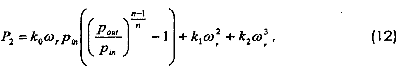
![]()
![]()
Das bedeutet, dass dieser Ausdruck anhand der Temperaturen Tin und Tout sowie der Drücke Pout und Pin wie folgt ermittelt werden kann: 
Die Motorleistung P1 kann in analoger Weise wie oben durch die Gleichung (8) angeben überwacht werden.The engine power P 1 can be monitored in a manner analogous to that indicated above by equation (8).
Anhand von
In diesem System ergeben sich folgende Variablen:
- Ti ∼ Temperatur am
Austritt des Verdampfers 3c - Th ∼ Temperatur am
Eintritt des Kondensators 5c - Tbox ∼ Temperatur im Kühlraum 7c
- Tamb ∼ Umgebungstemperatur
- Q 1 ∼ Kühlleistung
- Q 2 ∼ an die Umgebung abgegebene Leistung
- W ∼ von der Pumpe 2c abgegebene Leistung
- ωr ∼ Geschwindigkeit der Motorwelle [U/sec]
- Te ∼ Drehmoment [Nm]
- P 2 ∼ vom Motor abgegebene mechanische Leistung
- T i ∼ temperature at the outlet of the
evaporator 3c - T h ∼ temperature at the inlet of the
condenser 5c - T box ∼ temperature in the refrigerator compartment 7c
- T amb ∼ ambient temperature
- Q 1 ∼ cooling capacity
- Q 2 ∼ power emitted to the environment
- W ∼ power delivered by pump 2c
- ω r ∼ speed of the motor shaft [rev / sec]
- T e ∼ torque [Nm]
- P 2 ∼ mechanical power delivered by the motor
Diese stehen in folgendem mathematischen Zusammenhang: 
Die die Leistung des Motors 1c beschreibende Fläche gemäß Darstellung 14 entspricht der gemäß Darstellung 12 in 

Die Gleichung 15 beschreibt dabei die Leistung P2 am Eingang des Kompressors wohingegen die Gleichung 17 die Leistung am Ausgang des Kompressors beschreibt. Wie insbesondere die Darstellung 17 verdeutlicht, können die hier zur Ermittlung der Leistung an den Schnittstellen der Funktionseinheiten zu ermittelnden Flächen zwei- oder mehrdimensional sein. Die Fläche gemäß Darstellung 17 ist zweidimensional, also eine Linie. Die übrigen hier dargestellten Flächen sind sämtlichst dreidimensional. Es versteht sich, dass diese Flächen ggf. auch mehr als dreidimensional sein können, je nach Art der zu überwachenden Maschine und der dahinter stehenden mathematisch physikalischen Zusammenhänge.
Auch hier erfolgt die Überwachung in analoger Weise, indem die die Leistung an den Schnittstellen der Funktionseinheiten angebenden Flächen gemäß Darstellungen 14, 15 und 17 zum Zeitpunkt t1 sowie nach zeitlichem Abstand zum Zeitpunkt t2 ermittelt werden (es ergeben sich dann die Flächen gemäß den Darstellungen 14' 15' und 17'), um dann durch Ermittlung des Abstandes der Flächen bzw. das dazwischen aufgespannte Volumen zu ermitteln, welche der Funktionseinheiten 1 c, 2c, um welches Maß in ihrem Wirkungsgrad abgefallen sind.Here, too, the monitoring takes place in an analogous manner, in that the areas indicating the power at the interfaces of the functional units are determined according to
Schließlich ist anhand von
- q ∼ Volumenstrom des durch die Leitung 22 strömenden Wassers
- ṁg ∼ Abgasmasse
- Tw,out ∼ die Temperatur des aus der Leitung 22 austretenden Wassers
- T w,in ∼ die Temperatur des in die Leitung 22 eintretenden Wassers
- Tg.out ∼ die Temperatur des Abgases am Austritt
- Tg.in ∼ die Verbrennungstemperatur
- Tamb ∼ die Umgebungstemperatur
- P1 ∼ die durch den Brennstoff in das System eingebrachte Leistung
- P2 ∼ die durch das Wasser aus dem System abgeführte Leistung
- q ∼ volume flow rate of the water flowing through line 22
- ṁ g ∼ exhaust mass
- T w, out ∼ the temperature of the water emerging from line 22
- T w , in ∼ the temperature of the water entering the line 22
- T g.out ∼ the temperature of the exhaust gas at the outlet
- T g.in ∼ the combustion temperature
- T amb ∼ the ambient temperature
- P 1 ∼ the power brought into the system by the fuel
- P 2 ∼ the power removed from the system by the water
Hierbei ergeben sich folgende Zusammenhänge: ![]()

![]()
Wie die vorstehenden Ausführungsbeispiele verdeutlichen, kann das erfindungsgemäße Verfahren bei unterschiedlichsten Einrichtungen wie Aggregaten, Maschinen und Anlagen eingesetzt werden, wobei vorteilhaft stets die mehrdimensionalen Flächen ermittelt werden, welche jeweils die Leistung an den Schnittstellen der Funktionseinheiten zueinander in jedem beliebigen Betriebspunkt definieren und somit ein zuverlässiges Maß für die Leistungscharakteristik der Funktionseinheiten sowie bei entsprechender Auswertung der gesamten Einrichtung ergeben, wenn diese zu unterschiedlichen Zeitpunkten (z. B. t1 und t2) miteinander verglichen werden. Es versteht sich, dass die Zeitpunkte t1 und t2 hier nur beispielhaft zu verstehen sind, zweckmäßigerweise bleiben die zum Zeitpunkt t1 ermittelten Werte stets abgespeichert, um sie mit späteren vergleichen zu können, was jedoch nicht ausschließt, dass auch Zwischenwerte gespeichert werden um ggf. auch die Geschwindigkeit der Änderung zu erfassen. Auch dies kann in einer entsprechenden Auswerteinrichtung ausgewertet werden. Insoweit wird insbesondere auf
Es sei an dieser Stelle darauf hingewiesen, dass bei den vorstehend dargestellten Ausführungsbeispielen stets zwei- oder mehrdimensionale Flächen zur Ermittlung der Leistungsbilanz an den Schnittstellen der Funktionseinheiten verwendet worden sind, da dies eine Auswertung praktisch unabhängig vom jeweiligen Betriebspunkt ermöglicht. Die in Rede stehenden zwei- oder mehrdimensionalen Flächen werden vorteilhaft während des Betriebs ermittelt, wobei durch geeignete Iterationsverfahren versucht wird, unter Zugrundelegung möglichst weniger unterschiedlicher Betriebspunkte eine hohe Genauigkeit der Flächen zu erzielen. Dies kann insbesondere unter Verwendung des Kámánfilters erreicht werden, wie weiter oben schon beschrieben worden ist. Es können jedoch auch andere geeignete Iterationsverfahren Verwendung finden. Auch ist es denkbar, dass, beispielsweise bei einem Pumpenaggregat, bestimmte Betriebspunkte gezielt angefahren werden, um die die Leistungsbilanz repräsentierende Fläche mit möglichst hoher Genauigkeit zu erfassen oder durch gezieltes Anfahren von definierten Betriebspunkten auf das Ermitteln solcher Flächen verzichten zu können.It should be pointed out at this point that in the exemplary embodiments shown above, two- or multi-dimensional surfaces have always been used to determine the power balance at the interfaces of the functional units, since this enables an evaluation to be practically independent of the respective operating point. The two-dimensional or multi-dimensional surfaces in question are advantageously determined during operation, with attempts being made by means of suitable iteration methods to achieve a high level of accuracy of the surfaces on the basis of as few different operating points as possible. This can be achieved in particular using the Kámán filter, as has already been described above. However, other suitable iteration methods can also be used. It is also conceivable that, for example in the case of a pump unit, certain operating points are approached in a targeted manner in order to capture the area representing the power balance with the highest possible accuracy or to be able to dispense with determining such areas by specifically approaching defined operating points.
Claims (13)
- A method for monitoring an energy conversion device which consists of several function units which are functionally linked to one another, concerning which power-dependent variables of at least one function unit are automatically detected and/or computed in temporal intervals and are compared to one another or to values derived therefrom and/or to predefined values, and a corresponding signal is produced in dependence on the comparison, wherein power-dependent variables of at least two function units which are functionally linked to one another are detected and/or computed in an automatic manner in temporal intervals, and the power-dependent output variables or variables derived therefrom, of the one function unit, form the power-dependent input variables of the function unit which is functionally arranged subsequent to this and a multidimensional surface course which has a model character and is dependent on the power of a function unit is determined on the basis of several operating points and stored, characterised in that such surface courses are determined anew in temporal intervals and are compared to the previously determined ones.
- A method according to claim 1, characterised in that the volume spanned between the surfaces is used as a measure for the efficiency change, in particular an efficiency drop.
- A method according to claim 1 or 2, characterised in that a Kalman filter is used for determining the surface course on the basis of the operating points.
- A method according to one of the preceding claims, characterised in that it is used for operational optimisation and/or for monitoring the energy consumption or the efficiency of a pump assembly, in particular of an electromotorically driven centrifugal pump assembly, concerning which on operation, at least one power-dependent variable of the motor and at least one hydraulic variable of the pump or at least two hydraulic variables of the pump, at a temporal interval are compared to one another or are mathematically linked to one another or compared to predefined values, and a signal characterising the operating state of the pump assembly is produced in dependence on the comparison.
- A method according to claim 4, characterised in that it is carried out during the designated delivery operation.
- A method according to claim 4 to 5, characterised in that the detection of power-determining variables of the motor and/or pump is not effected until after the completion of a predefined time which corresponds at least to the running-in phase of the pump assembly.
- A method according to claim 6, characterised in that after completion of the predefined time, during the monitoring phase, automatically at least one operating profile is detected and the expected energy consumption is determined whilst taking into account the efficiency change which is possibly determined
- A centrifugal pump assembly with an electrical motor and a centrifugal pump driven by this, characterised in that a device for monitoring the power characteristics of at least one function unit of the assembly is provided, said device operating according to a method according to one of the preceding claims.
- A compressor assembly with an electrical motor and a displacement pump driven by this, characterised in that a device for monitoring the power characteristics of at least one function unit of the assembly is provided, said device operating according to a method according to one of the preceding claims.
- A cooling assembly with an electric motor, with a displacement pump driven by this, with an evaporator and with a condenser, characterised in that a device for monitoring the power characteristics of at least one function unit of the assembly is provided, said device functioning according to a method according to one of the preceding claims.
- A heating facility with a combustor and at least one water circuit which can be heated by this, characterised in that a device for monitoring the power characteristics of at least one function unit of the facility is provided, said device operating according to a method according to one of the preceding claims.
- 1 An assembly or facility according to one of the preceding claims, characterised in that after a predefined time after starting operation of the assembly or facility, the device automatically begins with the detection and storage of the variables which are relevant to determining the efficiency
- An assembly or facility according to claim 12, characterised in that the device comprises a measured value memory, in which at least the variables detected at the beginning of the measurement or variables derived therefrom are stored.
Priority Applications (5)
| Application Number | Priority Date | Filing Date | Title |
|---|---|---|---|
| EP07018530.1A EP2039939B2 (en) | 2007-09-20 | 2007-09-20 | Method for monitoring an energy conversion device |
| PCT/EP2008/007041 WO2009039934A1 (en) | 2007-09-20 | 2008-08-28 | Method for monitoring an energy conversion device |
| US12/679,054 US20100300220A1 (en) | 2007-09-20 | 2008-08-28 | Method for monitoring an energy conversion device |
| CN200880108089.6A CN101802413B (en) | 2007-09-20 | 2008-08-28 | Method for monitoring an energy conversion device |
| JP2010525224A JP5439378B2 (en) | 2007-09-20 | 2008-08-28 | Method for monitoring an energy conversion device |
Applications Claiming Priority (1)
| Application Number | Priority Date | Filing Date | Title |
|---|---|---|---|
| EP07018530.1A EP2039939B2 (en) | 2007-09-20 | 2007-09-20 | Method for monitoring an energy conversion device |
Publications (3)
| Publication Number | Publication Date |
|---|---|
| EP2039939A1 EP2039939A1 (en) | 2009-03-25 |
| EP2039939B1 EP2039939B1 (en) | 2017-08-09 |
| EP2039939B2 true EP2039939B2 (en) | 2020-11-18 |
Family
ID=39144574
Family Applications (1)
| Application Number | Title | Priority Date | Filing Date |
|---|---|---|---|
| EP07018530.1A Not-in-force EP2039939B2 (en) | 2007-09-20 | 2007-09-20 | Method for monitoring an energy conversion device |
Country Status (5)
| Country | Link |
|---|---|
| US (1) | US20100300220A1 (en) |
| EP (1) | EP2039939B2 (en) |
| JP (1) | JP5439378B2 (en) |
| CN (1) | CN101802413B (en) |
| WO (1) | WO2009039934A1 (en) |
Cited By (1)
| Publication number | Priority date | Publication date | Assignee | Title |
|---|---|---|---|---|
| EP4711241A1 (en) | 2024-09-12 | 2026-03-18 | KB Intellectual Property GmbH & Co. KG | Method and system for degradation detection of a power steering system |
Families Citing this family (14)
| Publication number | Priority date | Publication date | Assignee | Title |
|---|---|---|---|---|
| JP5437687B2 (en) * | 2009-04-14 | 2014-03-12 | ナブテスコ株式会社 | Actuator monitoring circuit, control device, and actuator unit |
| EP2440784B1 (en) * | 2009-06-12 | 2019-10-23 | Cidra Corporate Services, Inc. | Method and apparatus for predicting maintenance needs of a pump based at least partly on pump performance analysis |
| US20130204546A1 (en) * | 2012-02-02 | 2013-08-08 | Ghd Pty Ltd. | On-line pump efficiency determining system and related method for determining pump efficiency |
| JP2014202144A (en) * | 2013-04-05 | 2014-10-27 | 新日本造機株式会社 | Diagnostic method for centrifugal pump |
| JP6776078B2 (en) * | 2016-09-26 | 2020-10-28 | 朝日ライフサイエンス株式会社 | Freezer monitoring device, freezer monitoring system and freezer monitoring method |
| ES2982439T3 (en) * | 2016-12-30 | 2024-10-16 | Grundfos Holding As | Method for operating an electronically controlled pump unit |
| DE102018200651A1 (en) * | 2018-01-16 | 2019-07-18 | KSB SE & Co. KGaA | Method for the self-diagnosis of the mechanical and / or hydraulic condition of a centrifugal pump |
| ES3041905T3 (en) * | 2018-05-11 | 2025-11-17 | Grundfos Holding As | A monitoring module and method for identifying an operating scenario in a wastewater pumping station |
| FR3094421A1 (en) * | 2019-03-29 | 2020-10-02 | Wilo Intec | PREDICTIVE MAINTENANCE PROCEDURE FOR A FLUID CIRCULATION PUMP |
| EP4019779A1 (en) | 2020-12-23 | 2022-06-29 | Grundfos Holding A/S | A pump monitoring system and method for associating a current operating state of a pump system with one or more fault scenarios |
| CN114235271B (en) * | 2021-11-12 | 2024-01-12 | 潍柴动力股份有限公司 | Dew point detection method, device, storage medium and equipment for differential pressure sensor |
| DE102023111782A1 (en) | 2023-05-05 | 2024-11-07 | KSB SE & Co. KGaA | Method for detecting cavitation and/or air bubbles or air inflow within a hydraulic system |
| US20250042570A1 (en) * | 2023-07-31 | 2025-02-06 | United Airlines, Inc. | Cabin air compressor failure alert system |
| JP7814646B1 (en) * | 2025-06-27 | 2026-02-16 | 三菱電機株式会社 | Diagnostic equipment for electric motor load equipment |
Citations (4)
| Publication number | Priority date | Publication date | Assignee | Title |
|---|---|---|---|---|
| US4584654A (en) † | 1982-10-21 | 1986-04-22 | Ultra Products Systems, Inc. | Method and system for monitoring operating efficiency of pipeline system |
| US6260004B1 (en) † | 1997-12-31 | 2001-07-10 | Innovation Management Group, Inc. | Method and apparatus for diagnosing a pump system |
| US20030133808A1 (en) † | 2002-01-17 | 2003-07-17 | Itt Manufacturing Enterprises, Inc. | Centrifugal pump performance degradation detection |
| EP1171714B1 (en) † | 1999-03-24 | 2005-03-16 | ITT Manufacturing Enterprises | Apparatus and method for controlling a pump system |
Family Cites Families (24)
| Publication number | Priority date | Publication date | Assignee | Title |
|---|---|---|---|---|
| DE3402120A1 (en) | 1984-01-23 | 1985-07-25 | Rheinhütte vorm. Ludwig Beck GmbH & Co, 6200 Wiesbaden | METHOD AND DEVICE FOR CONTROLLING DIFFERENT OPERATING PARAMETERS FOR PUMPS AND COMPRESSORS |
| JPS6163491U (en) | 1984-10-02 | 1986-04-30 | ||
| JPH07117046B2 (en) * | 1988-12-27 | 1995-12-18 | 株式会社東芝 | Pump controller |
| US5742500A (en) | 1995-08-23 | 1998-04-21 | Irvin; William A. | Pump station control system and method |
| DE19618462A1 (en) * | 1996-05-08 | 1997-11-13 | Status Pro Maschinenmesstechni | Extrinsic power parameter determination method for energy conversion appliance |
| JP3343245B2 (en) | 1998-04-03 | 2002-11-11 | 株式会社荏原製作所 | Fluid machine diagnostic system |
| US20010010032A1 (en) * | 1998-10-27 | 2001-07-26 | Ehlers Gregory A. | Energy management and building automation system |
| US6584784B2 (en) * | 1999-02-05 | 2003-07-01 | Midwest Research Institute | Combined refrigeration system with a liquid pre-cooling heat exchanger |
| US6185944B1 (en) * | 1999-02-05 | 2001-02-13 | Midwest Research Institute | Refrigeration system with a compressor-pump unit and a liquid-injection desuperheating line |
| JP2003028076A (en) * | 2001-07-12 | 2003-01-29 | Hitachi Ltd | Pump abnormality diagnosis device |
| US7368853B2 (en) * | 2002-04-22 | 2008-05-06 | Elliptec Resonant Actuator Aktiengesellschaft | Piezoelectric motors and methods for the production and operation thereof |
| US6709240B1 (en) * | 2002-11-13 | 2004-03-23 | Eaton Corporation | Method and apparatus of detecting low flow/cavitation in a centrifugal pump |
| WO2005057086A1 (en) * | 2003-12-12 | 2005-06-23 | Rinnai Corporation | Hot water supply system |
| DE10359726A1 (en) | 2003-12-19 | 2005-07-14 | Ksb Aktiengesellschaft | quantity measurement |
| ATE389807T1 (en) | 2004-02-11 | 2008-04-15 | Grundfos As | METHOD FOR DETERMINING ERRORS DURING THE OPERATION OF A PUMP UNIT |
| JP4265982B2 (en) * | 2004-02-25 | 2009-05-20 | 三菱電機株式会社 | Equipment diagnostic equipment, refrigeration cycle equipment, refrigeration cycle monitoring system |
| US7406398B2 (en) * | 2004-06-05 | 2008-07-29 | Schlumberger Technology Corporation | System and method for determining pump underperformance |
| JP4625306B2 (en) * | 2004-10-28 | 2011-02-02 | 三菱重工業株式会社 | Fluid machinery performance diagnostic apparatus and system |
| JP2006226574A (en) * | 2005-02-16 | 2006-08-31 | Paloma Ind Ltd | Hot water circulation heating device |
| NZ538737A (en) * | 2005-03-10 | 2008-04-30 | Hot Water Innovations Ltd | Electronic control of water storage (hot water storage) parameters and operation |
| CN1693711A (en) * | 2005-06-03 | 2005-11-09 | 王黎明 | Intelligent control device for water pump electric machine |
| CN1302269C (en) * | 2005-12-16 | 2007-02-28 | 陈育青 | Method and apparatus for real-timely monitoring switch resistance of switch machine |
| CN101033744B (en) | 2006-03-08 | 2013-07-24 | Itt制造企业公司 | Pump protection method and apparatus without conventional sensors |
| DE102007022348A1 (en) | 2007-05-12 | 2008-11-13 | Ksb Aktiengesellschaft | Device and method for fault monitoring |
-
2007
- 2007-09-20 EP EP07018530.1A patent/EP2039939B2/en not_active Not-in-force
-
2008
- 2008-08-28 US US12/679,054 patent/US20100300220A1/en not_active Abandoned
- 2008-08-28 WO PCT/EP2008/007041 patent/WO2009039934A1/en not_active Ceased
- 2008-08-28 CN CN200880108089.6A patent/CN101802413B/en not_active Expired - Fee Related
- 2008-08-28 JP JP2010525224A patent/JP5439378B2/en not_active Expired - Fee Related
Patent Citations (4)
| Publication number | Priority date | Publication date | Assignee | Title |
|---|---|---|---|---|
| US4584654A (en) † | 1982-10-21 | 1986-04-22 | Ultra Products Systems, Inc. | Method and system for monitoring operating efficiency of pipeline system |
| US6260004B1 (en) † | 1997-12-31 | 2001-07-10 | Innovation Management Group, Inc. | Method and apparatus for diagnosing a pump system |
| EP1171714B1 (en) † | 1999-03-24 | 2005-03-16 | ITT Manufacturing Enterprises | Apparatus and method for controlling a pump system |
| US20030133808A1 (en) † | 2002-01-17 | 2003-07-17 | Itt Manufacturing Enterprises, Inc. | Centrifugal pump performance degradation detection |
Cited By (1)
| Publication number | Priority date | Publication date | Assignee | Title |
|---|---|---|---|---|
| EP4711241A1 (en) | 2024-09-12 | 2026-03-18 | KB Intellectual Property GmbH & Co. KG | Method and system for degradation detection of a power steering system |
Also Published As
| Publication number | Publication date |
|---|---|
| JP5439378B2 (en) | 2014-03-12 |
| US20100300220A1 (en) | 2010-12-02 |
| EP2039939A1 (en) | 2009-03-25 |
| CN101802413A (en) | 2010-08-11 |
| WO2009039934A1 (en) | 2009-04-02 |
| JP2010539380A (en) | 2010-12-16 |
| EP2039939B1 (en) | 2017-08-09 |
| CN101802413B (en) | 2014-07-30 |
Similar Documents
| Publication | Publication Date | Title |
|---|---|---|
| EP2039939B2 (en) | Method for monitoring an energy conversion device | |
| EP2145112B2 (en) | Device and method for fault monitoring | |
| DE10355651B4 (en) | Method for optimizing the efficiency of a motor operated under load | |
| EP1286240B1 (en) | Method of determining a pump-characteristic | |
| EP2258949B1 (en) | Method for recording characteristic values, in particular values, in particular of parameters of a centrifugal pump powered by an electric motor integrated into an assembly | |
| DE102011010218B4 (en) | A method of regulating the pressure of a fluid delivered by a variable speed pump | |
| EP2469094B1 (en) | Method for operating a double pump or multi pump assembly | |
| DE112013004970T5 (en) | Pressure control by means of a phase current and initial setting in a vehicle series | |
| EP1929151A1 (en) | Method for controlling a group of glow plugs for a diesel engine | |
| EP4224016A1 (en) | Electronic control device for a component of compressed air generation, compressed air conditioning, compressed air storage and / or compressed air distribution | |
| WO2018197033A1 (en) | Method for detecting an abnormal operating state of a pump unit | |
| EP3215763B1 (en) | Method for operating a fluid-guiding device, and corresponding fluid-guiding device | |
| DE112012005512T5 (en) | Methods and systems for monitoring and using a device for storing electrical energy | |
| WO2021052785A1 (en) | Method for monitoring an oil flow in an oil cooling circuit | |
| EP2220375B1 (en) | Fan arrangement | |
| DE19804330A1 (en) | Process for regulating a compressor | |
| EP3830422A1 (en) | Vacuum pump | |
| EP3298306B1 (en) | Method for operating an electrically actuable feed pump in a hydraulic circuit | |
| EP3058650B1 (en) | Method for controlling an electric motor of a vehicle pump | |
| WO2014094950A1 (en) | Method for reducing the particle emissions of an internal combustion engine and engine controller | |
| DE112009001698B4 (en) | Arrangement and method for the uninterrupted supply of a hydraulic system with a fluid | |
| DE102009056575B4 (en) | Method and device for determining a modeled temperature value in an internal combustion engine and method for plausibility of a temperature sensor | |
| DE102011008923B4 (en) | Method for controlling and/or regulating a hydraulic drive unit, hydraulic drive unit and injection molding machine | |
| DE102021211175A1 (en) | Method for operating an electric motor, feed pump, motor vehicle with such a feed pump, computer program and computer-readable medium | |
| EP1873898A2 (en) | Method for regulating a pump for conveying a liquid medium |
Legal Events
| Date | Code | Title | Description |
|---|---|---|---|
| PUAI | Public reference made under article 153(3) epc to a published international application that has entered the european phase |
Free format text: ORIGINAL CODE: 0009012 |
|
| AK | Designated contracting states |
Kind code of ref document: A1 Designated state(s): AT BE BG CH CY CZ DE DK EE ES FI FR GB GR HU IE IS IT LI LT LU LV MC MT NL PL PT RO SE SI SK TR |
|
| AX | Request for extension of the european patent |
Extension state: AL BA HR MK RS |
|
| 17P | Request for examination filed |
Effective date: 20090729 |
|
| 17Q | First examination report despatched |
Effective date: 20090826 |
|
| AKX | Designation fees paid |
Designated state(s): AT BE BG CH CY CZ DE DK EE ES FI FR GB GR HU IE IS IT LI LT LU LV MC MT NL PL PT RO SE SI SK TR |
|
| GRAP | Despatch of communication of intention to grant a patent |
Free format text: ORIGINAL CODE: EPIDOSNIGR1 |
|
| STAA | Information on the status of an ep patent application or granted ep patent |
Free format text: STATUS: GRANT OF PATENT IS INTENDED |
|
| INTG | Intention to grant announced |
Effective date: 20170123 |
|
| GRAS | Grant fee paid |
Free format text: ORIGINAL CODE: EPIDOSNIGR3 |
|
| GRAJ | Information related to disapproval of communication of intention to grant by the applicant or resumption of examination proceedings by the epo deleted |
Free format text: ORIGINAL CODE: EPIDOSDIGR1 |
|
| GRAL | Information related to payment of fee for publishing/printing deleted |
Free format text: ORIGINAL CODE: EPIDOSDIGR3 |
|
| STAA | Information on the status of an ep patent application or granted ep patent |
Free format text: STATUS: EXAMINATION IS IN PROGRESS |
|
| GRAR | Information related to intention to grant a patent recorded |
Free format text: ORIGINAL CODE: EPIDOSNIGR71 |
|
| STAA | Information on the status of an ep patent application or granted ep patent |
Free format text: STATUS: GRANT OF PATENT IS INTENDED |
|
| INTC | Intention to grant announced (deleted) | ||
| GRAA | (expected) grant |
Free format text: ORIGINAL CODE: 0009210 |
|
| STAA | Information on the status of an ep patent application or granted ep patent |
Free format text: STATUS: THE PATENT HAS BEEN GRANTED |
|
| INTG | Intention to grant announced |
Effective date: 20170629 |
|
| AK | Designated contracting states |
Kind code of ref document: B1 Designated state(s): AT BE BG CH CY CZ DE DK EE ES FI FR GB GR HU IE IS IT LI LT LU LV MC MT NL PL PT RO SE SI SK TR |
|
| REG | Reference to a national code |
Ref country code: GB Ref legal event code: FG4D Free format text: NOT ENGLISH |
|
| REG | Reference to a national code |
Ref country code: CH Ref legal event code: EP Ref country code: AT Ref legal event code: REF Ref document number: 917177 Country of ref document: AT Kind code of ref document: T Effective date: 20170815 |
|
| REG | Reference to a national code |
Ref country code: IE Ref legal event code: FG4D Free format text: LANGUAGE OF EP DOCUMENT: GERMAN |
|
| REG | Reference to a national code |
Ref country code: DE Ref legal event code: R096 Ref document number: 502007015791 Country of ref document: DE |
|
| REG | Reference to a national code |
Ref country code: FR Ref legal event code: PLFP Year of fee payment: 11 |
|
| REG | Reference to a national code |
Ref country code: NL Ref legal event code: MP Effective date: 20170809 |
|
| REG | Reference to a national code |
Ref country code: LT Ref legal event code: MG4D |
|
| PG25 | Lapsed in a contracting state [announced via postgrant information from national office to epo] |
Ref country code: FI Free format text: LAPSE BECAUSE OF FAILURE TO SUBMIT A TRANSLATION OF THE DESCRIPTION OR TO PAY THE FEE WITHIN THE PRESCRIBED TIME-LIMIT Effective date: 20170809 Ref country code: SE Free format text: LAPSE BECAUSE OF FAILURE TO SUBMIT A TRANSLATION OF THE DESCRIPTION OR TO PAY THE FEE WITHIN THE PRESCRIBED TIME-LIMIT Effective date: 20170809 Ref country code: LT Free format text: LAPSE BECAUSE OF FAILURE TO SUBMIT A TRANSLATION OF THE DESCRIPTION OR TO PAY THE FEE WITHIN THE PRESCRIBED TIME-LIMIT Effective date: 20170809 Ref country code: NL Free format text: LAPSE BECAUSE OF FAILURE TO SUBMIT A TRANSLATION OF THE DESCRIPTION OR TO PAY THE FEE WITHIN THE PRESCRIBED TIME-LIMIT Effective date: 20170809 |
|
| PG25 | Lapsed in a contracting state [announced via postgrant information from national office to epo] |
Ref country code: ES Free format text: LAPSE BECAUSE OF FAILURE TO SUBMIT A TRANSLATION OF THE DESCRIPTION OR TO PAY THE FEE WITHIN THE PRESCRIBED TIME-LIMIT Effective date: 20170809 Ref country code: LV Free format text: LAPSE BECAUSE OF FAILURE TO SUBMIT A TRANSLATION OF THE DESCRIPTION OR TO PAY THE FEE WITHIN THE PRESCRIBED TIME-LIMIT Effective date: 20170809 Ref country code: GR Free format text: LAPSE BECAUSE OF FAILURE TO SUBMIT A TRANSLATION OF THE DESCRIPTION OR TO PAY THE FEE WITHIN THE PRESCRIBED TIME-LIMIT Effective date: 20171110 Ref country code: IS Free format text: LAPSE BECAUSE OF FAILURE TO SUBMIT A TRANSLATION OF THE DESCRIPTION OR TO PAY THE FEE WITHIN THE PRESCRIBED TIME-LIMIT Effective date: 20171209 Ref country code: PL Free format text: LAPSE BECAUSE OF FAILURE TO SUBMIT A TRANSLATION OF THE DESCRIPTION OR TO PAY THE FEE WITHIN THE PRESCRIBED TIME-LIMIT Effective date: 20170809 Ref country code: BG Free format text: LAPSE BECAUSE OF FAILURE TO SUBMIT A TRANSLATION OF THE DESCRIPTION OR TO PAY THE FEE WITHIN THE PRESCRIBED TIME-LIMIT Effective date: 20171109 |
|
| PG25 | Lapsed in a contracting state [announced via postgrant information from national office to epo] |
Ref country code: RO Free format text: LAPSE BECAUSE OF FAILURE TO SUBMIT A TRANSLATION OF THE DESCRIPTION OR TO PAY THE FEE WITHIN THE PRESCRIBED TIME-LIMIT Effective date: 20170809 Ref country code: CZ Free format text: LAPSE BECAUSE OF FAILURE TO SUBMIT A TRANSLATION OF THE DESCRIPTION OR TO PAY THE FEE WITHIN THE PRESCRIBED TIME-LIMIT Effective date: 20170809 Ref country code: DK Free format text: LAPSE BECAUSE OF FAILURE TO SUBMIT A TRANSLATION OF THE DESCRIPTION OR TO PAY THE FEE WITHIN THE PRESCRIBED TIME-LIMIT Effective date: 20170809 |
|
| REG | Reference to a national code |
Ref country code: CH Ref legal event code: PL |
|
| REG | Reference to a national code |
Ref country code: DE Ref legal event code: R026 Ref document number: 502007015791 Country of ref document: DE |
|
| PLBI | Opposition filed |
Free format text: ORIGINAL CODE: 0009260 |
|
| PLAX | Notice of opposition and request to file observation + time limit sent |
Free format text: ORIGINAL CODE: EPIDOSNOBS2 |
|
| PG25 | Lapsed in a contracting state [announced via postgrant information from national office to epo] |
Ref country code: EE Free format text: LAPSE BECAUSE OF FAILURE TO SUBMIT A TRANSLATION OF THE DESCRIPTION OR TO PAY THE FEE WITHIN THE PRESCRIBED TIME-LIMIT Effective date: 20170809 Ref country code: SK Free format text: LAPSE BECAUSE OF FAILURE TO SUBMIT A TRANSLATION OF THE DESCRIPTION OR TO PAY THE FEE WITHIN THE PRESCRIBED TIME-LIMIT Effective date: 20170809 Ref country code: MC Free format text: LAPSE BECAUSE OF FAILURE TO SUBMIT A TRANSLATION OF THE DESCRIPTION OR TO PAY THE FEE WITHIN THE PRESCRIBED TIME-LIMIT Effective date: 20170809 |
|
| 26 | Opposition filed |
Opponent name: KSB AKTIENGESELLSCHAFT Effective date: 20180508 |
|
| REG | Reference to a national code |
Ref country code: IE Ref legal event code: MM4A |
|
| REG | Reference to a national code |
Ref country code: BE Ref legal event code: MM Effective date: 20170930 |
|
| PG25 | Lapsed in a contracting state [announced via postgrant information from national office to epo] |
Ref country code: LU Free format text: LAPSE BECAUSE OF NON-PAYMENT OF DUE FEES Effective date: 20170920 |
|
| PG25 | Lapsed in a contracting state [announced via postgrant information from national office to epo] |
Ref country code: IE Free format text: LAPSE BECAUSE OF NON-PAYMENT OF DUE FEES Effective date: 20170920 Ref country code: LI Free format text: LAPSE BECAUSE OF NON-PAYMENT OF DUE FEES Effective date: 20170930 Ref country code: CH Free format text: LAPSE BECAUSE OF NON-PAYMENT OF DUE FEES Effective date: 20170930 |
|
| PG25 | Lapsed in a contracting state [announced via postgrant information from national office to epo] |
Ref country code: SI Free format text: LAPSE BECAUSE OF FAILURE TO SUBMIT A TRANSLATION OF THE DESCRIPTION OR TO PAY THE FEE WITHIN THE PRESCRIBED TIME-LIMIT Effective date: 20170809 Ref country code: BE Free format text: LAPSE BECAUSE OF NON-PAYMENT OF DUE FEES Effective date: 20170930 |
|
| REG | Reference to a national code |
Ref country code: FR Ref legal event code: PLFP Year of fee payment: 12 |
|
| PG25 | Lapsed in a contracting state [announced via postgrant information from national office to epo] |
Ref country code: MT Free format text: LAPSE BECAUSE OF FAILURE TO SUBMIT A TRANSLATION OF THE DESCRIPTION OR TO PAY THE FEE WITHIN THE PRESCRIBED TIME-LIMIT Effective date: 20170809 |
|
| PLBB | Reply of patent proprietor to notice(s) of opposition received |
Free format text: ORIGINAL CODE: EPIDOSNOBS3 |
|
| REG | Reference to a national code |
Ref country code: AT Ref legal event code: MM01 Ref document number: 917177 Country of ref document: AT Kind code of ref document: T Effective date: 20170920 |
|
| PG25 | Lapsed in a contracting state [announced via postgrant information from national office to epo] |
Ref country code: AT Free format text: LAPSE BECAUSE OF NON-PAYMENT OF DUE FEES Effective date: 20170920 |
|
| PG25 | Lapsed in a contracting state [announced via postgrant information from national office to epo] |
Ref country code: HU Free format text: LAPSE BECAUSE OF FAILURE TO SUBMIT A TRANSLATION OF THE DESCRIPTION OR TO PAY THE FEE WITHIN THE PRESCRIBED TIME-LIMIT; INVALID AB INITIO Effective date: 20070920 |
|
| PG25 | Lapsed in a contracting state [announced via postgrant information from national office to epo] |
Ref country code: CY Free format text: LAPSE BECAUSE OF NON-PAYMENT OF DUE FEES Effective date: 20170809 |
|
| APAH | Appeal reference modified |
Free format text: ORIGINAL CODE: EPIDOSCREFNO |
|
| APBM | Appeal reference recorded |
Free format text: ORIGINAL CODE: EPIDOSNREFNO |
|
| APBP | Date of receipt of notice of appeal recorded |
Free format text: ORIGINAL CODE: EPIDOSNNOA2O |
|
| PLAB | Opposition data, opponent's data or that of the opponent's representative modified |
Free format text: ORIGINAL CODE: 0009299OPPO |
|
| PG25 | Lapsed in a contracting state [announced via postgrant information from national office to epo] |
Ref country code: TR Free format text: LAPSE BECAUSE OF FAILURE TO SUBMIT A TRANSLATION OF THE DESCRIPTION OR TO PAY THE FEE WITHIN THE PRESCRIBED TIME-LIMIT Effective date: 20170809 |
|
| APBM | Appeal reference recorded |
Free format text: ORIGINAL CODE: EPIDOSNREFNO |
|
| APBP | Date of receipt of notice of appeal recorded |
Free format text: ORIGINAL CODE: EPIDOSNNOA2O |
|
| R26 | Opposition filed (corrected) |
Opponent name: KSB SE & CO. KGAA Effective date: 20180508 |
|
| PG25 | Lapsed in a contracting state [announced via postgrant information from national office to epo] |
Ref country code: PT Free format text: LAPSE BECAUSE OF FAILURE TO SUBMIT A TRANSLATION OF THE DESCRIPTION OR TO PAY THE FEE WITHIN THE PRESCRIBED TIME-LIMIT Effective date: 20170809 |
|
| APBU | Appeal procedure closed |
Free format text: ORIGINAL CODE: EPIDOSNNOA9O |
|
| PUAH | Patent maintained in amended form |
Free format text: ORIGINAL CODE: 0009272 |
|
| STAA | Information on the status of an ep patent application or granted ep patent |
Free format text: STATUS: PATENT MAINTAINED AS AMENDED |
|
| 27A | Patent maintained in amended form |
Effective date: 20201118 |
|
| AK | Designated contracting states |
Kind code of ref document: B2 Designated state(s): AT BE BG CH CY CZ DE DK EE ES FI FR GB GR HU IE IS IT LI LT LU LV MC MT NL PL PT RO SE SI SK TR |
|
| REG | Reference to a national code |
Ref country code: DE Ref legal event code: R102 Ref document number: 502007015791 Country of ref document: DE |
|
| REG | Reference to a national code |
Ref country code: DE Ref legal event code: R082 Ref document number: 502007015791 Country of ref document: DE |
|
| PGFP | Annual fee paid to national office [announced via postgrant information from national office to epo] |
Ref country code: GB Payment date: 20230920 Year of fee payment: 17 |
|
| PGFP | Annual fee paid to national office [announced via postgrant information from national office to epo] |
Ref country code: FR Payment date: 20230928 Year of fee payment: 17 Ref country code: DE Payment date: 20230920 Year of fee payment: 17 |
|
| PGFP | Annual fee paid to national office [announced via postgrant information from national office to epo] |
Ref country code: IT Payment date: 20230927 Year of fee payment: 17 |
|
| REG | Reference to a national code |
Ref country code: DE Ref legal event code: R119 Ref document number: 502007015791 Country of ref document: DE |
|
| GBPC | Gb: european patent ceased through non-payment of renewal fee |
Effective date: 20240920 |
|
| PG25 | Lapsed in a contracting state [announced via postgrant information from national office to epo] |
Ref country code: DE Free format text: LAPSE BECAUSE OF NON-PAYMENT OF DUE FEES Effective date: 20250401 |
|
| PG25 | Lapsed in a contracting state [announced via postgrant information from national office to epo] |
Ref country code: GB Free format text: LAPSE BECAUSE OF NON-PAYMENT OF DUE FEES Effective date: 20240920 |
|
| PG25 | Lapsed in a contracting state [announced via postgrant information from national office to epo] |
Ref country code: IT Free format text: LAPSE BECAUSE OF NON-PAYMENT OF DUE FEES Effective date: 20240920 |
|
| PG25 | Lapsed in a contracting state [announced via postgrant information from national office to epo] |
Ref country code: FR Free format text: LAPSE BECAUSE OF NON-PAYMENT OF DUE FEES Effective date: 20240930 |