EP4365003A2 - Fahrzeugbedientafel - Google Patents
Fahrzeugbedientafel Download PDFInfo
- Publication number
- EP4365003A2 EP4365003A2 EP23206976.5A EP23206976A EP4365003A2 EP 4365003 A2 EP4365003 A2 EP 4365003A2 EP 23206976 A EP23206976 A EP 23206976A EP 4365003 A2 EP4365003 A2 EP 4365003A2
- Authority
- EP
- European Patent Office
- Prior art keywords
- pointer
- digital screen
- control panel
- support ring
- actuator device
- Prior art date
- Legal status (The legal status is an assumption and is not a legal conclusion. Google has not performed a legal analysis and makes no representation as to the accuracy of the status listed.)
- Pending
Links
- 230000005291 magnetic effect Effects 0.000 claims abstract description 11
- 230000008878 coupling Effects 0.000 claims abstract description 5
- 238000010168 coupling process Methods 0.000 claims abstract description 5
- 238000005859 coupling reaction Methods 0.000 claims abstract description 5
- 239000011521 glass Substances 0.000 description 11
- 239000004973 liquid crystal related substance Substances 0.000 description 5
- 238000005516 engineering process Methods 0.000 description 2
- 239000003302 ferromagnetic material Substances 0.000 description 2
- 238000004519 manufacturing process Methods 0.000 description 2
- 239000010763 heavy fuel oil Substances 0.000 description 1
- 239000000463 material Substances 0.000 description 1
- 230000003287 optical effect Effects 0.000 description 1
- 230000002093 peripheral effect Effects 0.000 description 1
- 230000001360 synchronised effect Effects 0.000 description 1
- 238000002834 transmittance Methods 0.000 description 1
Images


Classifications
-
- B—PERFORMING OPERATIONS; TRANSPORTING
- B60—VEHICLES IN GENERAL
- B60K—ARRANGEMENT OR MOUNTING OF PROPULSION UNITS OR OF TRANSMISSIONS IN VEHICLES; ARRANGEMENT OR MOUNTING OF PLURAL DIVERSE PRIME-MOVERS IN VEHICLES; AUXILIARY DRIVES FOR VEHICLES; INSTRUMENTATION OR DASHBOARDS FOR VEHICLES; ARRANGEMENTS IN CONNECTION WITH COOLING, AIR INTAKE, GAS EXHAUST OR FUEL SUPPLY OF PROPULSION UNITS IN VEHICLES
- B60K35/00—Instruments specially adapted for vehicles; Arrangement of instruments in or on vehicles
- B60K35/20—Output arrangements, i.e. from vehicle to user, associated with vehicle functions or specially adapted therefor
- B60K35/21—Output arrangements, i.e. from vehicle to user, associated with vehicle functions or specially adapted therefor using visual output, e.g. blinking lights or matrix displays
- B60K35/211—Output arrangements, i.e. from vehicle to user, associated with vehicle functions or specially adapted therefor using visual output, e.g. blinking lights or matrix displays producing three-dimensional [3D] effects, e.g. stereoscopic images
-
- B—PERFORMING OPERATIONS; TRANSPORTING
- B60—VEHICLES IN GENERAL
- B60K—ARRANGEMENT OR MOUNTING OF PROPULSION UNITS OR OF TRANSMISSIONS IN VEHICLES; ARRANGEMENT OR MOUNTING OF PLURAL DIVERSE PRIME-MOVERS IN VEHICLES; AUXILIARY DRIVES FOR VEHICLES; INSTRUMENTATION OR DASHBOARDS FOR VEHICLES; ARRANGEMENTS IN CONNECTION WITH COOLING, AIR INTAKE, GAS EXHAUST OR FUEL SUPPLY OF PROPULSION UNITS IN VEHICLES
- B60K35/00—Instruments specially adapted for vehicles; Arrangement of instruments in or on vehicles
- B60K35/50—Instruments characterised by their means of attachment to or integration in the vehicle
-
- B—PERFORMING OPERATIONS; TRANSPORTING
- B60—VEHICLES IN GENERAL
- B60K—ARRANGEMENT OR MOUNTING OF PROPULSION UNITS OR OF TRANSMISSIONS IN VEHICLES; ARRANGEMENT OR MOUNTING OF PLURAL DIVERSE PRIME-MOVERS IN VEHICLES; AUXILIARY DRIVES FOR VEHICLES; INSTRUMENTATION OR DASHBOARDS FOR VEHICLES; ARRANGEMENTS IN CONNECTION WITH COOLING, AIR INTAKE, GAS EXHAUST OR FUEL SUPPLY OF PROPULSION UNITS IN VEHICLES
- B60K35/00—Instruments specially adapted for vehicles; Arrangement of instruments in or on vehicles
- B60K35/20—Output arrangements, i.e. from vehicle to user, associated with vehicle functions or specially adapted therefor
- B60K35/21—Output arrangements, i.e. from vehicle to user, associated with vehicle functions or specially adapted therefor using visual output, e.g. blinking lights or matrix displays
- B60K35/215—Output arrangements, i.e. from vehicle to user, associated with vehicle functions or specially adapted therefor using visual output, e.g. blinking lights or matrix displays characterised by the combination of multiple visual outputs, e.g. combined instruments with analogue meters and additional displays
-
- B—PERFORMING OPERATIONS; TRANSPORTING
- B60—VEHICLES IN GENERAL
- B60K—ARRANGEMENT OR MOUNTING OF PROPULSION UNITS OR OF TRANSMISSIONS IN VEHICLES; ARRANGEMENT OR MOUNTING OF PLURAL DIVERSE PRIME-MOVERS IN VEHICLES; AUXILIARY DRIVES FOR VEHICLES; INSTRUMENTATION OR DASHBOARDS FOR VEHICLES; ARRANGEMENTS IN CONNECTION WITH COOLING, AIR INTAKE, GAS EXHAUST OR FUEL SUPPLY OF PROPULSION UNITS IN VEHICLES
- B60K35/00—Instruments specially adapted for vehicles; Arrangement of instruments in or on vehicles
- B60K35/20—Output arrangements, i.e. from vehicle to user, associated with vehicle functions or specially adapted therefor
- B60K35/21—Output arrangements, i.e. from vehicle to user, associated with vehicle functions or specially adapted therefor using visual output, e.g. blinking lights or matrix displays
- B60K35/22—Display screens
-
- B—PERFORMING OPERATIONS; TRANSPORTING
- B60—VEHICLES IN GENERAL
- B60K—ARRANGEMENT OR MOUNTING OF PROPULSION UNITS OR OF TRANSMISSIONS IN VEHICLES; ARRANGEMENT OR MOUNTING OF PLURAL DIVERSE PRIME-MOVERS IN VEHICLES; AUXILIARY DRIVES FOR VEHICLES; INSTRUMENTATION OR DASHBOARDS FOR VEHICLES; ARRANGEMENTS IN CONNECTION WITH COOLING, AIR INTAKE, GAS EXHAUST OR FUEL SUPPLY OF PROPULSION UNITS IN VEHICLES
- B60K35/00—Instruments specially adapted for vehicles; Arrangement of instruments in or on vehicles
- B60K35/60—Instruments characterised by their location or relative disposition in or on vehicles
-
- B—PERFORMING OPERATIONS; TRANSPORTING
- B60—VEHICLES IN GENERAL
- B60K—ARRANGEMENT OR MOUNTING OF PROPULSION UNITS OR OF TRANSMISSIONS IN VEHICLES; ARRANGEMENT OR MOUNTING OF PLURAL DIVERSE PRIME-MOVERS IN VEHICLES; AUXILIARY DRIVES FOR VEHICLES; INSTRUMENTATION OR DASHBOARDS FOR VEHICLES; ARRANGEMENTS IN CONNECTION WITH COOLING, AIR INTAKE, GAS EXHAUST OR FUEL SUPPLY OF PROPULSION UNITS IN VEHICLES
- B60K2360/00—Indexing scheme associated with groups B60K35/00 or B60K37/00 relating to details of instruments or dashboards
- B60K2360/1523—Matrix displays
-
- B—PERFORMING OPERATIONS; TRANSPORTING
- B60—VEHICLES IN GENERAL
- B60K—ARRANGEMENT OR MOUNTING OF PROPULSION UNITS OR OF TRANSMISSIONS IN VEHICLES; ARRANGEMENT OR MOUNTING OF PLURAL DIVERSE PRIME-MOVERS IN VEHICLES; AUXILIARY DRIVES FOR VEHICLES; INSTRUMENTATION OR DASHBOARDS FOR VEHICLES; ARRANGEMENTS IN CONNECTION WITH COOLING, AIR INTAKE, GAS EXHAUST OR FUEL SUPPLY OF PROPULSION UNITS IN VEHICLES
- B60K2360/00—Indexing scheme associated with groups B60K35/00 or B60K37/00 relating to details of instruments or dashboards
- B60K2360/20—Optical features of instruments
- B60K2360/33—Illumination features
- B60K2360/336—Light guides
-
- B—PERFORMING OPERATIONS; TRANSPORTING
- B60—VEHICLES IN GENERAL
- B60K—ARRANGEMENT OR MOUNTING OF PROPULSION UNITS OR OF TRANSMISSIONS IN VEHICLES; ARRANGEMENT OR MOUNTING OF PLURAL DIVERSE PRIME-MOVERS IN VEHICLES; AUXILIARY DRIVES FOR VEHICLES; INSTRUMENTATION OR DASHBOARDS FOR VEHICLES; ARRANGEMENTS IN CONNECTION WITH COOLING, AIR INTAKE, GAS EXHAUST OR FUEL SUPPLY OF PROPULSION UNITS IN VEHICLES
- B60K2360/00—Indexing scheme associated with groups B60K35/00 or B60K37/00 relating to details of instruments or dashboards
- B60K2360/60—Structural details of dashboards or instruments
- B60K2360/68—Features of instruments
- B60K2360/682—Arrangements to cover or hide instruments
-
- B—PERFORMING OPERATIONS; TRANSPORTING
- B60—VEHICLES IN GENERAL
- B60K—ARRANGEMENT OR MOUNTING OF PROPULSION UNITS OR OF TRANSMISSIONS IN VEHICLES; ARRANGEMENT OR MOUNTING OF PLURAL DIVERSE PRIME-MOVERS IN VEHICLES; AUXILIARY DRIVES FOR VEHICLES; INSTRUMENTATION OR DASHBOARDS FOR VEHICLES; ARRANGEMENTS IN CONNECTION WITH COOLING, AIR INTAKE, GAS EXHAUST OR FUEL SUPPLY OF PROPULSION UNITS IN VEHICLES
- B60K2360/00—Indexing scheme associated with groups B60K35/00 or B60K37/00 relating to details of instruments or dashboards
- B60K2360/60—Structural details of dashboards or instruments
- B60K2360/68—Features of instruments
- B60K2360/693—Cover plate features
-
- B—PERFORMING OPERATIONS; TRANSPORTING
- B60—VEHICLES IN GENERAL
- B60K—ARRANGEMENT OR MOUNTING OF PROPULSION UNITS OR OF TRANSMISSIONS IN VEHICLES; ARRANGEMENT OR MOUNTING OF PLURAL DIVERSE PRIME-MOVERS IN VEHICLES; AUXILIARY DRIVES FOR VEHICLES; INSTRUMENTATION OR DASHBOARDS FOR VEHICLES; ARRANGEMENTS IN CONNECTION WITH COOLING, AIR INTAKE, GAS EXHAUST OR FUEL SUPPLY OF PROPULSION UNITS IN VEHICLES
- B60K2360/00—Indexing scheme associated with groups B60K35/00 or B60K37/00 relating to details of instruments or dashboards
- B60K2360/60—Structural details of dashboards or instruments
- B60K2360/68—Features of instruments
- B60K2360/698—Pointers of combined instruments
- B60K2360/6985—Pointers of combined instruments with only part of pointer being visible
-
- B—PERFORMING OPERATIONS; TRANSPORTING
- B60—VEHICLES IN GENERAL
- B60K—ARRANGEMENT OR MOUNTING OF PROPULSION UNITS OR OF TRANSMISSIONS IN VEHICLES; ARRANGEMENT OR MOUNTING OF PLURAL DIVERSE PRIME-MOVERS IN VEHICLES; AUXILIARY DRIVES FOR VEHICLES; INSTRUMENTATION OR DASHBOARDS FOR VEHICLES; ARRANGEMENTS IN CONNECTION WITH COOLING, AIR INTAKE, GAS EXHAUST OR FUEL SUPPLY OF PROPULSION UNITS IN VEHICLES
- B60K2360/00—Indexing scheme associated with groups B60K35/00 or B60K37/00 relating to details of instruments or dashboards
- B60K2360/92—Manufacturing of instruments
- B60K2360/96—Manufacturing of instruments by assembling
-
- B—PERFORMING OPERATIONS; TRANSPORTING
- B60—VEHICLES IN GENERAL
- B60K—ARRANGEMENT OR MOUNTING OF PROPULSION UNITS OR OF TRANSMISSIONS IN VEHICLES; ARRANGEMENT OR MOUNTING OF PLURAL DIVERSE PRIME-MOVERS IN VEHICLES; AUXILIARY DRIVES FOR VEHICLES; INSTRUMENTATION OR DASHBOARDS FOR VEHICLES; ARRANGEMENTS IN CONNECTION WITH COOLING, AIR INTAKE, GAS EXHAUST OR FUEL SUPPLY OF PROPULSION UNITS IN VEHICLES
- B60K37/00—Dashboards
- B60K37/20—Dashboard panels
Definitions
- the present invention relates to a vehicle control panel.
- the present invention advantageously applies to a car control panel, to which the following description will make explicit reference without thereby losing generality.
- a car includes a dashboard, which forms the front wall of the driver and passenger compartment located beneath the windscreen.
- the dashboard supports a control panel, which is arranged in front of the driver immediately behind the steering wheel.
- control panel only included analogue instruments with pointers and a few warning lights; small digital screens gradually appeared, which over time became increasingly larger and more defined to show increasingly complex images until they became fully programmable.
- digital screens replaced the mileometer and some of the warning lights, subsequently they replaced the secondary analogue instruments (such as for example the residual fuel indicator and the clock), and eventually in some cases they also replaced the main analogue instruments (i.e. the speedometer and the rev counter) forming a fully digital instrumentation.
- the fully digital instrumentation is usually very appreciated at "cruising" speed (especially in cities) because, being fully programmable, it allows useful driving information to be highlighted (for instance the speed of the vehicle which is an indispensable information for compliance with the limits set by the law and the navigator) so that the useful driving information can be read easily and immediately without having to overly distract the eye from the road.
- fully digital instrumentation is generally less appreciated in “sporty” driving, particularly in on-track driving, as it is deemed to be less immediately readable (i.e., it requires greater attention to acquire the information displayed by the instrumentation as a "quick glance" is not generally sufficient).
- Patent EP3138722B1 describes a control panel comprising a digital screen and an analogue instrument provided with a circular support element and a pointer that moves within the support element; the analogue instrument is movable so as to be placed only when required in a working position, in which the analogue instrument overlaps the digital screen so that the support element of the analogue instrument covers a corresponding part of the digital screen itself.
- Patent application US20170253178A1 describes a display device for a vehicle and comprising a liquid crystal panel which provides a display surface, where an image is displayed, and a backlight which emits light on the liquid crystal panel from behind, a real object placed between the liquid crystal panel and the backlight and visible through the liquid crystal panel, and a controller which controls the liquid crystal panel so that a specific pixel region of the display surface behind which the real object is placed has a higher light transmittance than another pixel region of the display surface.
- the object of the present invention is to provide a vehicle control panel, which allows information to be displayed so that the driver can, in all driving situations, capture the data he/she needs with the least amount of distraction.
- a vehicle control panel is provided, as claimed in the appended claims.
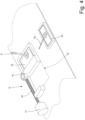
- Number 1 in Figure 1 indicates, as a whole, a car dashboard.
- the dashboard 1 supports a control panel 2, which is arranged in front of the driver behind a steering wheel 3.
- the control panel 2 is arranged above a support body which houses, on the inside, the steering shaft (i.e., the element at one end of which the steering wheel 3 is mounted).
- the control panel 2 comprises a box-shaped housing body 4, which is substantially parallelepiped in shape (with rounded edges) and shaped like a cup to contain, on the inside, all the components of the control panel 2; in particular, the housing body 4 has an open end, which faces the steering wheel 3 (i.e., towards the driver) and is closed by a main transparent panel 5 which reproduces the shape of the housing body 4 so as to engage the entire area of the housing body 4.
- the housing body 4 comprises a connecting element, which protrudes in a cantilevered manner from a lower wall of the housing body 4 and is configured to attach the housing body 4 to the dashboard 1 of the vehicle; in particular, the connecting element is a ring that is fitted around a cylindrical support of the dashboard 1.
- the control panel 2 comprises a main digital screen 6 (for example made with the LED or OLED technology), which is arranged in the housing body 4 below the main transparent panel 5 and reproduces the shape of the housing body 4 so as to engage the entire area of the housing body 4.
- the main digital screen 6 has at least one through opening 7, which is cut into the main digital screen 6 and completely surrounded by the main digital screen 6.
- one larger through opening 7 at the centre and two or more smaller through openings 7 at the sides may be present; that is, one through opening 7 arranged at the centre has a greater size than the sizes of the other two through openings 7 arranged at the ends, and the two through openings 7 arranged at the ends have the same size.
- two (or more) larger through openings 7 arranged at the centre and a few smaller through openings 7 arranged at the sides may be present.
- the through opening 7 cut through the main digital screen 6 has a circular (round) shape; in the case of three through openings 7, the radius of the through opening 7 arranged at the centre would preferably be larger than the radius of the two through openings 7 arranged at the ends.
- one or more through openings 7 cut through the main digital screen 6 have a different shape from the circular shape (e.g., a rectangular or elliptical shape).
- the control panel 2 comprises a secondary digital screen 8 (for example made with the LED or OLED technology), which is arranged behind the main digital screen 6 in the area of the through opening 7 of the main digital screen 6 so that it is visible through the through opening 7.
- the secondary digital screen 8 has the same shape and the same size as the through opening 7 of the main digital screen 6, so that it completely engages the through opening 7 and does not protrude significantly beyond the through opening 7; in any case, the secondary digital screen 8 has a size that is not smaller than the size of the through opening 7, such as to completely close the empty space of the through opening 7.
- the secondary digital screen 8 is arranged behind the main digital screen 6 (and at a short, yet non-null distance from the main digital screen 6), thus pointing out the step resulting from the through opening 7 of the main digital screen 6.
- a different number of through openings 7 and, hence, of corresponding secondary digital screens 8 is provided (e.g., one secondary digital screen 8 or two, four or five secondary digital screens 8).
- the size, position or shape of the through openings 7 and, hence, of the secondary digital screens 8 may be different.
- the control panel 2 comprises a pointer 9 (which is arranged between the main digital screen 6 and the secondary digital screen 8; that is, the pointer 9 is located behind the main digital screen 6 (thus it is only visible through the through opening 7) and in front of the secondary digital screen 8 so as to overlap (when necessary) the secondary digital screen 8.
- the pointer 9 is mounted in a movable manner so as to move (when necessary) on the secondary digital screen 8 to indicate information displayed by the secondary digital screen 8.
- the number and arrangement of the pointers 9 could be different and, for example, two or more pointers 9 could be coupled to the same secondary digital screen 8.
- the central secondary digital screen 8 is coupled to a single pointer 9, which is the only one cooperating with the central secondary digital screen 8, whereas each side secondary digital screen 8 is coupled to two pointers 9, which both cooperate with the same side secondary digital screen 8; the two pointers 9 cooperating together with the same side secondary digital screen 8 can be arranged aligned and facing each other to move together in a synchronized manner or can be moved independently of one another.
- each secondary digital screen 8 is coupled to a single pointer 9.
- the pointer 9 has a visible part (that is, it can overlap the respective secondary digital screen 8) extending from the edge of the secondary digital screen 8 towards the centre of the secondary digital screen 8; that is, the pointer 9 has a peripheral positioning since its visible part starts from the edge (from the periphery) of the secondary digital screen 8.
- the pointer 9 is U-shaped and encloses the secondary digital screen 8 from the outside; i.e., the pointer 9 has a visible part that can be arranged in front of the secondary digital screen 8 and a hidden part that is always arranged behind the digital screen 8 and is connected by a U-curve to the visible part.
- the main transparent panel 5 covering the main digital screen 6 has a through opening 10 which is arranged in the area of the through opening 7 of the main digital screen 6 and has the same shape and the same size as the through opening 7 of the main digital screen 6 (alternatively, the through opening 10 may be larger than the through opening 7 of the main digital screen 6).
- the control panel 2 comprises a secondary transparent panel 11 which is arranged in the area of the through opening 10 of the main transparent panel 5 and covers the secondary digital screen 8.
- the secondary transparent panel 11 is not coplanar with the main transparent panel 5 and is arranged further back than the main transparent panel 5 (i.e., further away from the driver than the main transparent panel 5); alternatively, the secondary transparent panel 11 is arranged further forward than the main transparent panel 5 (i.e., closer to the driver than the main transparent panel 5), or the secondary transparent panel 11 is coplanar with the main transparent panel 5.
- the main transparent panel 5 has no through opening 10 and seamlessly covers both the main digital screen 6 and the secondary digital screens 8.
- the control panel 2 comprises an actuator device 12 which is configured to move the pointer 9 (or the pointers 9) on the corresponding secondary digital screen 8.
- the actuator device 12 directly supports the pointer 9 (or the pointers 9).
- the actuator device 12 is mounted in a movable manner so as to move between an operating position (shown in the attached figures), in which the pointer 9 overlaps the secondary digital screen 8 and, hence, is visible through the through opening 7 of the main digital screen 6, and a rest position, in which the pointer 9 is arranged beside the secondary digital screen 8 (i.e., it is arranged behind the main digital screen 6) so as not to be visible through the through opening 7 of the main digital screen 6.
- the movement of the actuator device 12 (which directly supports the pointer 9) allows the pointer 9 to overlap the secondary digital screen 8, to make the pointer 9 visible through the through opening 7 of the main digital screen 6, and alternatively allows the pointer 9 to hide behind the main digital screen 6 so that the pointer 9 is hidden from view (i.e., the pointer 9 is no longer visible through the through opening 7 of the main digital screen 6 as it is located beside and not upon the secondary digital screen 8 and therefore is located beside the through opening 7 and hidden from view by the main digital screen 6).
- the control panel 2 comprises an actuator device 13 which is configured to move the actuator device 12 between the operating position and the rest position.
- the actuator device 12 is mounted on a slide 14 which slides along a fixed guide 15, and the actuator device 13 comprises a worm screw 16, which engages a threaded hole made in the slide 14, and an electric motor 17, which causes the rotation of the worm screw 16.
- the control panel 2 comprises an additional pointer 18, which is arranged between the main digital screen 6 and the central secondary digital screen 8 and is mounted in a movable manner so as to move on the central secondary digital screen 8.
- the control panel 2 also comprises an actuator device 19 (shown in Figures 2 , 3 and 4 ), which is configured to move the pointer 18 on the central secondary digital screen 8 and directly supports the pointer 18.
- the actuator device 19 is mounted in a fixed position inside the housing body 4 and therefore never changes its position.
- two different pointers 9 and 18 actuated by corresponding actuator devices 12 and 19 can move on the central secondary digital screen 8.
- the pointer 9 is moved (both in the area of the through opening 7 of the main digital screen 6 so as to be visible through the through opening 7, and beside the through opening 7 so as not to be visible through the through opening 7) by an actuator device 20 that transmits motion to the pointer 9 through a contactless magnetic coupling. That is, the actuator device 20 has no component that is physically in contact with the pointer 9 and is only bound to the pointer 9 by means of a contactless magnetic coupling.
- the actuator device 20 comprises a slider 21, which is arranged behind the secondary digital screen 8, is always aligned with the pointer 9 and magnetically attracts the pointer 9 to itself.
- the slider 21 supports a permanent magnet 22 which is designed to generate a relatively strong magnetic field so that the influence of the magnetic field also extends beyond the secondary digital screen 8 to magnetically attract the pointer 9.
- the secondary digital screen 8 is made so as to be unaffected by the magnetic field (i.e., so as not to be affected by the presence of the permanent magnet 22).
- the secondary digital screen 8 may also contain ferromagnetic material which allows the influence of the magnetic field to be increased beyond the secondary digital screen 8 (as it reduces the width of the air gap existing between the permanent magnet 22 and the pointer 9).
- the pointer 9 is obviously made of ferromagnetic material (to be magnetically attracted by the permanent magnet 22) and could also be magnetized with a polarity opposite to a polarity of the permanent magnet 22 to increase the magnetic attraction force between the permanent magnet 22 and the pointer 9.
- the secondary digital screen 8 is slightly larger than the through opening 7, so that when the pointer 9 is arranged on the edge of the secondary digital screen 8 the pointer 9 is not visible through the through opening 7 (in fact, the pointer 9 cannot be moved beyond the secondary digital screen 8 as it must always remain on the secondary digital screen 8 to slide on the secondary digital screen 8).
- a back surface of the pointer 9 that slides on the secondary digital screen 8 (and is pressed against the secondary digital screen 8 by the magnetic attraction force generated by the permanent magnet 22) may have a low friction outer layer (i.e., made of a material with a low friction coefficient).
- the actuator device 20 comprises a motor 23 that moves the slider 21; in the embodiment shown in Figure 6 , the motor 23 only generates a rotary movement but alternatively the motor 23 may only generate a translation movement or a roto-translation movement.
- the pointer 9 is moved (both in the area of the through opening 7 of the main digital screen 6 so as to be visible through the through opening 7, and beside the through opening 7 so as not to be visible through the through opening 7) by an actuator device 24 that transmits motion to the pointer 9 through a mechanical contact coupling. That is, the actuator device 24 is in physical contact with the pointer 9 and is bound to the pointer 9.
- the actuator device 24 comprises a support ring 25, which is mounted so as to rotate around a central rotation axis 26 and supports the pointer 9: the rotation of the support ring 25 around the rotation axis 26 also causes the rotation of the pointer 9 around the rotation axis 26.
- the support ring 25 is arranged above (i.e., in an upper plane) the secondary digital screen 8 (i.e., it is arranged between the secondary digital screen 8 and the through opening 7 of the main digital screen 6) so that the pointer 9 carried by the support ring 25 can be arranged on the secondary digital screen 8 (i.e., it can overlap the secondary digital screen 8).
- the support ring 25 has an inner diameter that is greater (larger) than an inner diameter of the through opening 7 of the main digital screen 6 so as not to be visible in any way through the through opening 7 and so as not to overlap the part of the secondary digital screen 8 visible through the through opening 7; in addition, preferably, the support ring 25 has an inner diameter that is greater (larger) than an outer diameter of the secondary digital screen 8 so as not to cover an edge of the secondary digital screen 8.
- the support ring 25 is inserted inside a containing ring 27 which is fixed (i.e., it is attached to the housing body 4) and coaxial to the support ring 25 so that the support ring 25 is free to slide (i.e., to rotate around the rotation axis 26) relative to the containing ring 27.
- the containing ring 27 has, on the inside, an annular seat which slidably accommodates the support ring 25 to allow the support ring 25 to slide (i.e., to rotate around the rotation axis 26) relative to the containing ring 27.
- an annular rack 28 is present within the support ring 25 (i.e., at the inner surface of the support ring 25).
- the actuator device 24 comprises a motor 29 (shown in Figure 7 ) which causes the rotation of a gear wheel meshing with the annular rack 28 so as to cause the rotation of the support ring 25 around the rotation axis 26 and relative to the containing ring 27 (i.e., inside the containing ring 27).
- the pointer 9 is mounted on the support ring 25 so as to rotate, relative to the support ring 25, around a rotation axis 30 parallel to the rotation axis 26.
- a central element 31 is provided, which is mounted in a rotary manner on the support ring 25 and from which the pointer 9 radially protrudes in a cantilever fashion; underneath, the central element 31 has a circular pin 32 engaging a circular seat 33 of the support ring 25 to be free to rotate, within the seat 33 of the support ring 25, around the rotation axis 30.
- Two appendages 34 and 35 which are arranged on the opposite side relative to the pointer 9, radially protrude in a cantilever fashion from the central element 31.
- the containing ring 27 is fitted with a countering body 36, which axially protrudes from a top surface of the containing ring 27 and is arranged so as to hit against the appendages 34 and 35 during the rotation of the support ring 25 relative to the containing ring 27.
- the countering body 36 has a cavity 37, which is open towards the centre (i.e., towards the rotation axis 26) and is shaped so as to contain, on the inside, the appendage 35.
- the pointer 9 is mounted on the support ring 25 so as to rotate, relative to the support ring 25, around the rotation axis 30 (parallel to the rotation axis 26) between an operating position (shown in Figure 9 ), in which the pointer 9 is oriented radially (i.e., perpendicularly to the rotation axis 26) and overlaps the secondary digital screen 8 so as to be visible through the through opening 7 of the main digital screen 6, and a rest position (shown in Figure 10 ), in which the pointer 9 is oriented circumferentially (i.e., transversely to the rotation axis 26) so as not to overlap the secondary digital screen 8 and, hence, not to be visible through the through opening 7 of the main digital screen 6.
- the pointer 9 is inserted in a seat 38 which is cut into the support ring 25 and is oriented circumferentially.
- the actuator device 24 comprises a pushing device 39, which is configured to push the pointer 9 towards the operating position (shown in Figure 9 ) with a predetermined force, without however preventing the pointer 9 from moving to the rest position (shown in Figure 10 ) overcoming the force generated by the pushing device 39.
- the pushing device 39 comprises an elastic element (typically a spring working by torsion), which generates an elastic force pushing the pointer 9 towards the operating position (shown in Figure 9 ).
- the pushing device 39 comprises two magnets (one housed in the central element 31 and the other arranged in the support ring 25), which are arranged aligned with one another and with opposite polarities when the pointer 9 is in the operating position (shown in Figure 9 ), and are perpendicular to one another when the pointer 9 is in the rest position (shown in Figure 10 ).
- the force generated by the pushing device 39 keeps the pointer 9 in the operating position (shown in Figure 9 ) and thus the pointer 9 is oriented radially and overlaps the secondary digital screen 8 so as to be visible through the through opening 7 of the main digital screen 6; by rotating the support body 25 around the rotation axis 26, the pointer 9 is moved along the secondary digital screen 8 to cooperate with the secondary digital screen 8.
- the pointer 9 is forced to rotate around the rotation axis 30 to move from the operating position (shown in Figure 9 ) to the rest position (shown in Figure 10 ), overcoming the force generated by the pushing device 39 (which tends to hold the pointer 9 in the operating position).
- the rotation of the pointer 9 around the rotation axis 30 initiated by the impact of the appendage 34 against the countering body 36 continues and brings the appendage 35 into the cavity 37 of the countering body 36, thus ending the rotation of the pointer 9 around the rotation axis 30 and arranging the pointer 9 in the rest position (shown in Figure 10 ).
- two collimated sheets of glass 40 are interposed between the main digital screen 6 and the main transparent panel 5 (i.e., on the main digital screen 6).
- Each collimated sheet of glass 40 consists of a bundle of parallel optical fibres placed side by side and fused together to form a single indivisible element and has the property of making an image on the bottom of the collimated sheet of glass 40 appear to the human eye as if it were on the top of the collimated sheet of glass 40. That is, looking through a collimated sheet of glass 40 at an image that is on the bottom wall of the collimated sheet of glass 40, the image appears to the human eye as if it were on the top wall of the collimated sheet of glass 40. Essentially, the collimated sheet of glass 40 brings the images closer to the observer without magnifying them.
- the purpose of the collimated sheets of glass 40 is to make pieces of information displayed by the main digital screen 6 appear closer to the driver so as to highlight them compared to other pieces of information displayed by the main digital screen 6.
- collimated sheets of glass 40 are envisaged. According to other embodiments, not shown, a different number, a different arrangement and/or a different shape of the collimated sheets of glass 40 are envisaged. According to other embodiments, not shown, the collimated sheets of glass 40 also overlap the secondary digital screens 8 or only overlap the secondary digital screens 8.
- control panel 2 described above advantageously applies to any type of road vehicle (for instance, a car or a motorcycle) and also to any type of off-road vehicle.
- control panel 2 described above has many advantages.
- control panel 2 allows information to be displayed so that the driver can, in all driving situations, capture the data he/she needs with the least amount of distraction.
- This result is achieved by the fact that, depending on the driving situation, the information can be displayed in a completely digital form (i.e., without using the pointers 9 and 18 which remain hidden behind the main digital screen 6 and therefore completely invisible to the driver) or in a hybrid form (i.e., partly digitally and partly analogically using the pointers 9 and 18 which are moved on the secondary digital screens 8).
- the information displayed in the completely digital form can be more complete and more detailed, whereas the information displayed in the hybrid form is less complete and less detailed but more quickly perceptible (as it is sufficient to see the position of the pointers 9 and 18 without actually reading the numerical scale associated with the pointers 9 and 18) .
- control panel 2 described above allows information to be displayed using only the digital screen 6 and 8 when the driver requires the display of complex information (typically a chart navigator during "cruising" speed) and also allows the pointers 9 and 18 to overlap the secondary digital screens 8 so as to faithfully recreate the appearance (particularly the three-dimensionality) of an analogue instrument when the driver requires this type of instrumentation for a "sporty" driving style.
- the control panel 2 described above does not reflect a watered-down compromise between the need of having a large digital screen and the conflicting need of also having a large analogue instrument; in fact, the control panel 2 described above makes it possible to have (at different times) both a large digital screen and an analogue instrument, depending on the driver's wishes.
- control panel 2 described above has particularly small overall dimensions and, hence, can be integrated into any type of vehicle.
- control panel 2 described above has a relatively low manufacturing cost as it uses simple components that are easily available on the market.
Landscapes
- Engineering & Computer Science (AREA)
- Chemical & Material Sciences (AREA)
- Combustion & Propulsion (AREA)
- Transportation (AREA)
- Mechanical Engineering (AREA)
- Instrument Panels (AREA)
Applications Claiming Priority (1)
| Application Number | Priority Date | Filing Date | Title |
|---|---|---|---|
| IT202200022758 | 2022-11-04 |
Publications (1)
| Publication Number | Publication Date |
|---|---|
| EP4365003A2 true EP4365003A2 (de) | 2024-05-08 |
Family
ID=84943657
Family Applications (2)
| Application Number | Title | Priority Date | Filing Date |
|---|---|---|---|
| EP23206969.0A Pending EP4365002A3 (de) | 2022-11-04 | 2023-10-31 | Fahrzeugbedientafel |
| EP23206976.5A Pending EP4365003A2 (de) | 2022-11-04 | 2023-10-31 | Fahrzeugbedientafel |
Family Applications Before (1)
| Application Number | Title | Priority Date | Filing Date |
|---|---|---|---|
| EP23206969.0A Pending EP4365002A3 (de) | 2022-11-04 | 2023-10-31 | Fahrzeugbedientafel |
Country Status (2)
| Country | Link |
|---|---|
| US (2) | US20240149684A1 (de) |
| EP (2) | EP4365002A3 (de) |
Citations (2)
| Publication number | Priority date | Publication date | Assignee | Title |
|---|---|---|---|---|
| US20170253178A1 (en) | 2014-09-05 | 2017-09-07 | Denso Corporation | Display device |
| EP3138722B1 (de) | 2015-09-04 | 2018-08-22 | FERRARI S.p.A. | Armaturenbrett für ein strassenfahrzeug |
Family Cites Families (1)
| Publication number | Priority date | Publication date | Assignee | Title |
|---|---|---|---|---|
| US7731374B2 (en) * | 2005-10-24 | 2010-06-08 | Continental Automotive Systems Us, Inc. | Reconfigurable instrument cluster |
-
2023
- 2023-10-31 EP EP23206969.0A patent/EP4365002A3/de active Pending
- 2023-10-31 EP EP23206976.5A patent/EP4365003A2/de active Pending
- 2023-11-01 US US18/499,474 patent/US20240149684A1/en active Pending
- 2023-11-01 US US18/499,477 patent/US20240149685A1/en active Pending
Patent Citations (2)
| Publication number | Priority date | Publication date | Assignee | Title |
|---|---|---|---|---|
| US20170253178A1 (en) | 2014-09-05 | 2017-09-07 | Denso Corporation | Display device |
| EP3138722B1 (de) | 2015-09-04 | 2018-08-22 | FERRARI S.p.A. | Armaturenbrett für ein strassenfahrzeug |
Also Published As
| Publication number | Publication date |
|---|---|
| US20240149684A1 (en) | 2024-05-09 |
| EP4365002A2 (de) | 2024-05-08 |
| US20240149685A1 (en) | 2024-05-09 |
| EP4365002A3 (de) | 2024-08-28 |
Similar Documents
| Publication | Publication Date | Title |
|---|---|---|
| US7482915B2 (en) | Vehicular display device | |
| CN106687772B (zh) | 显示装置 | |
| US10953748B2 (en) | Multi-layer display for vehicle dash | |
| US9919600B2 (en) | Vehicle information display systems | |
| JP3731739B2 (ja) | 車両用メータ | |
| JP2013147196A (ja) | 車両用表示装置 | |
| JP4234040B2 (ja) | 車両用表示装置 | |
| JP2018124118A (ja) | 車両用表示装置および車両用表示装置の表示方法 | |
| JP5406007B2 (ja) | 計器装置 | |
| EP4365003A2 (de) | Fahrzeugbedientafel | |
| CN102741728B (zh) | 特别是用于机动车辆的显示装置 | |
| EP3138722B1 (de) | Armaturenbrett für ein strassenfahrzeug | |
| EP2146187B1 (de) | Fahrzeug-anzeigevorrichtung | |
| CN102126434A (zh) | 刻度仪 | |
| JP2018162979A (ja) | 車両用表示装置 | |
| EP4365000A2 (de) | Bedienungstafel mit umkehrbarer blende für ein fahrzeug | |
| JP2006284460A (ja) | 計器用駆動機構及びこれを備える計器 | |
| JP6400185B2 (ja) | 車両用表示装置 | |
| JP2017181555A (ja) | 表示装置 | |
| JP2012198130A (ja) | 車両用表示装置 | |
| JP6179380B2 (ja) | 車両用表示装置 | |
| JP6238966B2 (ja) | 導光被覆要素、計器パネル、及び導光被覆要素の製造方法 | |
| JP2007155677A (ja) | 車両用指針計器 | |
| JP2003194588A (ja) | 表示装置 | |
| JP6361548B2 (ja) | 車両用表示装置 |
Legal Events
| Date | Code | Title | Description |
|---|---|---|---|
| PUAI | Public reference made under article 153(3) epc to a published international application that has entered the european phase |
Free format text: ORIGINAL CODE: 0009012 |
|
| STAA | Information on the status of an ep patent application or granted ep patent |
Free format text: STATUS: THE APPLICATION HAS BEEN PUBLISHED |
|
| AK | Designated contracting states |
Kind code of ref document: A2 Designated state(s): AL AT BE BG CH CY CZ DE DK EE ES FI FR GB GR HR HU IE IS IT LI LT LU LV MC ME MK MT NL NO PL PT RO RS SE SI SK SM TR |