EP4359256B1 - Containerverriegelungsvorrichtung sowie containerverriegelungsverfahren - Google Patents
Containerverriegelungsvorrichtung sowie containerverriegelungsverfahren Download PDFInfo
- Publication number
- EP4359256B1 EP4359256B1 EP22735767.0A EP22735767A EP4359256B1 EP 4359256 B1 EP4359256 B1 EP 4359256B1 EP 22735767 A EP22735767 A EP 22735767A EP 4359256 B1 EP4359256 B1 EP 4359256B1
- Authority
- EP
- European Patent Office
- Prior art keywords
- locking
- container
- locking bolt
- horizontal
- wedge slide
- Prior art date
- Legal status (The legal status is an assumption and is not a legal conclusion. Google has not performed a legal analysis and makes no representation as to the accuracy of the status listed.)
- Active
Links
Images


Classifications
-
- B—PERFORMING OPERATIONS; TRANSPORTING
- B60—VEHICLES IN GENERAL
- B60P—VEHICLES ADAPTED FOR LOAD TRANSPORTATION OR TO TRANSPORT, TO CARRY, OR TO COMPRISE SPECIAL LOADS OR OBJECTS
- B60P7/00—Securing or covering of load on vehicles
- B60P7/06—Securing of load
- B60P7/13—Securing freight containers or forwarding containers on vehicles
- B60P7/132—Securing freight containers or forwarding containers on vehicles twist-locks for containers or frames
-
- B—PERFORMING OPERATIONS; TRANSPORTING
- B60—VEHICLES IN GENERAL
- B60Y—INDEXING SCHEME RELATING TO ASPECTS CROSS-CUTTING VEHICLE TECHNOLOGY
- B60Y2200/00—Type of vehicle
- B60Y2200/10—Road Vehicles
- B60Y2200/14—Trucks; Load vehicles, Busses
- B60Y2200/147—Trailers, e.g. full trailers or caravans
Definitions
- the invention relates to a container locking device on a vehicle for locking a container to be transported on a loading area of the vehicle with a corner fitting, comprising a locking housing, a locking bolt and a drive, wherein the locking bolt has a shaft and a locking head which, in the unlocked state, can be inserted through an opening in the corner fitting of the container and, in the locked state, secures the container via projections engaging behind the opening of the corner fitting, the locking bolt with its shaft is mounted in the locking housing so as to be both axially displaceable and rotatable about its axis, a wedge slide is mounted laterally in the locking housing, i.e.
- the invention further relates to a container locking method that can be carried out using the above-mentioned device.
- Such a locking device for containers on a vehicle is known from EP 1 075 400 B1 known.
- a diaphragm accumulator drive is proposed as the drive for the linear movement, which is only held in its working position when compressed air is applied and is returned to its released position by means of a spring when the pressure drops.
- this locking device it is therefore necessary to first activate the drive by applying compressed air before loading the vehicle in order to bring the locking device into its unlocked state in order to then be able to load the container with its corner fitting via the unlocked locking head.
- the diaphragm accumulator spring is then loaded, it returns to its basic position, causing the locking bolt to rotate and lower.
- the DE 102 02 190 A1 describes a EP 1 075 400 B1 similar container locking device, but in which the locking bolt on its shaft does not have a tangential, rising recess to its circumference, but rather two pairs of cams arranged laterally one above the other and offset.
- the device can also have an additional safety device that prevents the pivot pin from being pulled out vertically in the direction of the container in all positions of the locking bolt (pivot pin).
- the disadvantage is that the additional safety device has to be set and released manually.
- the DE 10 2006 002 654 A1 a device for actuating a lock of a locking head with a corner fitting of a container is known, which has a pneumatic piston-cylinder arrangement with which an extendable and lowerable claw of the locking head can be brought from a retracted position to an extended position and from there to the locking position and back again.
- an additional lock is not provided, so that the device is held in the locking position by the pneumatic drive alone.
- a technically similar design with a hydraulic actuation is known from DE 20 2008 011 526 U1 known
- double locking systems In order to be able to load containers without a gooseneck tunnel onto such gooseneck trailers or chassis, so-called double locking systems are known, in which a console that can be swivelled around a horizontal axis can be folded down to the position of the locking bolt so that this console can be locked to the locking bolt and offers a raised support surface for containers without a gooseneck tunnel.
- This console usually has a conventional twist lock for locking the container.
- Such a double locking system is known, for example, from the company Jost-Werke GmbH, Siemens No, 63263 Neu-Isenburg, under the designation FB 88-14V.
- Such a double locking system is also available in the EP 0 934 848 A2 and in further training also in the DE 10 2014 218 891 A1 described.
- the EP 3 666 591 A1 describes a container locking system with horizontal and vertical locking options that can be operated independently of each other.
- the locking bolt has a Spring loading in the direction of the transport state and a run-on slope at its end facing the corner fitting, the locking bolt having a first locking position for the transport state of the locking bolt and a second locking position for the retracted unloading state and a sensing device for determining the loading state of the loading area, the locking bolt being manually brought into the unloading state for unloading and released by the sensing device after unloading.
- the sensing device arranged next to the locking bolt allows it to be determined that a container is resting in the loading position.
- the disadvantage is that the sensing device is made up of many parts and can lead to malfunctions due to its complexity, for example if it is not properly maintained, and the locking device is expensive to manufacture.
- the DE 197 20 238 A1 describes a container locking device with a rotationally driven locking head, in which a horizontally movable plug pin for so-called gooseneck container chassis is simultaneously extended laterally via a gear segment with the rotational movement.
- the DE 10 2004 045 665 A1 shows a cross member for front-side installation in a chassis, in which a twistlock and a horizontal plug pin are arranged so that they can be moved independently of each other.
- the JP 2011-051559 A describes a container chassis with horizontal and vertical locking devices that can be operated by means of adjusting cylinders.
- a horizontal locking bolt is additionally mounted in the locking housing so that it can be moved axially and horizontally, whereby a gooseneck container is arranged horizontally next to and adjacent to the locking housing with its corner fitting when loaded on the vehicle, the horizontal locking bolt has a free end which, when unlocked, does not protrude laterally beyond the locking housing and, when locked, engages in a lateral opening of the corner fitting of the gooseneck container and secures the gooseneck container via the opening, and the wedge slide is mounted so that it can move back and forth in the horizontal direction of movement of the horizontal locking bolt and is connected to the horizontal locking bolt, provides a double locking system which can secure both conventional containers with a locking system that engages vertically from below and gooseneck containers, i.e. containers with a gooseneck tunnel with an actively driven horizontal locking system.
- the wedge slide is mounted so that it can move back and forth in a horizontal plane perpendicular to the direction of movement of the horizontal locking bolt, and the horizontal locking bolt is operatively connected to the wedge slide via a wedge slide.
- This also provides a double locking system that can secure both conventional containers with a locking system that engages vertically from below, and gooseneck containers, i.e. containers with a gooseneck tunnel with an actively driven horizontal locking system.
- the movement deflection from the Wedge slide rotated 90° on the horizontal locking bolt creates a compact drive option that preserves valuable loading length on the vehicle.
- the drive has a double-acting pneumatic cylinder with a laterally movable piston rod, whereby the piston rod is operatively connected to the wedge slide in such a way that an idle stroke occurs during the first part of the stroke movement of the drive and the lateral movement of the wedge slide occurs during the second part of the stroke movement, the wedge slide is only actuated in the second part of the stroke movement.
- a locking device is arranged on the locking housing, which has a spring-loaded lock that is designed to engage in the lateral movement path of the wedge slide, moving the wedge slide and thus the horizontal locking bolt is achieved in a technically simple manner.
- the locking device activates a positive lock that prevents the locking device from being accidentally reopened, both with regard to the horizontal locking bolt and the locking bolt, by the lock in the movement path of the wedge slide.
- the locking device has a release mechanism for the lock, which releases the lock during the idle stroke, makes it possible for the locking device to be released during the idle stroke, i.e. in the first part of the stroke movement of the piston rod, so that the locking device can be opened from the locked state to the unlocked state.
- an emergency release is provided with which the positive locking of the locking device can be unlocked.
- the emergency release has two push elements equipped with external threads, in which the first push element is inserted into a first Threaded hole in the locking device and the second push element can be screwed into a second threaded hole in the locking housing, whereby the first push element releases the lock and the second push element moves the wedge slide to open the lock.
- the locking device can thus be released with the first push element and the locking device can be adjusted from the locked state to the unlocked state with the second push element, without the need for force to be applied via the pneumatic cylinder (emergency release). Accordingly, a container or even a gooseneck container can be unloaded by manually operating the emergency release if the pneumatic system fails.
- the wedge slide has a second driver that engages in the wedge slide, whereby the wedge slide has an actuating bevel that interacts with a bearing surface of the horizontal locking bolt for the axial movement of the horizontal locking bolt, the first horizontal, lateral movement of the wedge slide is converted via the actuating bevel in the wedge slide into a perpendicular, second horizontal movement of the axially displaceably mounted horizontal locking bolt, whereby the wedge slide can be actuated in a known manner by a hydraulic cylinder arranged in its direction of movement, without this drive causing a further shortening of the usable loading length.
- the container locking method is characterized in that an idle stroke is carried out during a first part of the lifting movement of the drive and the wedge slide is moved during a second part of the lifting movement, whereby when unlocking a container/gooseneck container from the locked state to the unlocked state, the lock is released during the first part of the lifting movement in the idle stroke and then during the second part of the lifting movement the wedge slide and thus the horizontal locking bolt is moved back and in parallel the locking bolt is first raised and then turned back to the unlocked state.
- FIG. 1 A first embodiment of the container locking device is shown in a spatial view, which is mounted on a loading area of a vehicle F, in particular on the front end of a gooseneck trailer. is provided on which a container to be transported is to be placed.
- the locking device has a locking housing 1, which has a drive box 10 and a guide component 11 with a load-bearing surface 12 built on it.
- the guide component 11 projects beyond the loading area.
- the upwardly projecting guide component 11 fits into a corner fitting of the container, whereby the container rests securely on the loading area, in particular the load-bearing surface 12.
- a gooseneck container is loaded, it is loaded with its two front corner fittings resting against a locking housing 1 arranged there on the gooseneck trailer in a slightly lower position.
- the locking device is in Fig. 1 in the unlocked state, ready to load or unload a (gooseneck) container, and in Fig. 2 in the locked state, in which the (gooseneck) container is positively and force-locked to the loading area of the vehicle (gooseneck trailer).
- a locking bolt 2 is provided, which is arranged in a central and vertical axis Z (see Fig. 4b ) is mounted in the guide component 11 so as to be axially displaceable and rotatable.
- the locking bolt 2 has a cylindrical shaft 20 which is mounted and held in the locking housing 1 so as to be axially displaceable and rotatable.
- the locking bolt 2 has a locking head 21 at the upper end of the shaft 20 which has a mushroom-like but elliptical contour and which, in an unlocked state, rests congruently on the guide component 11 and can be adjusted to a locked state in which the locking head 21 is rotated by 90 ° and lowered so that the projections now protruding from the elliptical locking head 21 over the guide component 11 engage behind the corner fitting of the loaded container.
- a horizontal locking bolt 7 is provided, which in the horizontal direction of movement of a retracted position in the unlocked state ( Fig. 1 ), in which the horizontal locking bolt 7 does not protrude beyond the locking housing 1, into a forward position in the locked state, in which the horizontal locking bolt 7 protrudes with a free end 71 beyond the locking housing 1 and there engages laterally in an opening of the corner fitting of the gooseneck container.
- Fig. 3 to 7 The exact mode of operation and the required components of the container locking device are described in the Fig. 3 to 7 in a top view of the container locking device (each for part figure a) and a cross-section (each for part figure b).
- FIG. 3 The container locking device is shown in its unlocked state, in which a container can be unloaded or loaded.
- a container can be unloaded or loaded.
- the locking bolt 2 with its shaft 20 is in an elevated position, i.e. axially displaced upwards, and the locking head 21 belonging to the locking bolt 2 rests on the guide component 11, as can be seen in particular from Fig. 3b can be seen.
- a container with its corner fitting and its slot-like opening formed therein can be loaded onto the loading surface and in particular onto the load-bearing surface 12 via the locking head 21 and the guide component 11 or lifted from the loaded position, since the locking head 21 is aligned with the guide component 11 (see top view).
- Fig. 3a Furthermore, the horizontal locking bolt 7 is in its retracted position, in which the horizontal locking bolt 7 does not protrude beyond the locking housing 1.
- the drive 3 can be seen in the form of a double-acting pneumatic cylinder 30, which is arranged in the drive box 10 of the locking housing 1.
- the double-acting pneumatic cylinder 30 has a piston rod 31, which interacts via a drive claw 32 with a wedge slide 4 that can be moved back and forth in the drive box 10 parallel to the pneumatic cylinder 30 via a driver 41.
- a driver 41 Regarding the design of the wedge slide 4 and its operative connection to the locking bolt 2, reference is made to the not yet published DE 10 2021 112 894 of the same applicant, how the required rotational movement of the shaft 20 and thus of the locking head 21 as well as the lowering and raising are realized.
- Fig. 5 the further movement sequence in the direction of the locked state is shown, whereby the piston rod 31 of the pneumatic cylinder 30 is extended even further and thus the wedge slide 4 is moved even further in the horizontal direction of movement H (in Fig. 5a downwards). Accordingly, the free end 71 of the horizontal locking bolt 7 protrudes even further and, in parallel, the locking head 21 is turned even further to the left (see Fig. 5a compared to Fig. 4a ).
- Fig. 6 the locked state is then reached, in which the locking head 21 is now rotated by 90 ° and lowered between the guide component 11 (see Fig. 6a and 6b ).
- the Horizontal locking bolt 7 can also be seen with its free end 71 protruding far in its locked state.
- the free end 71 of the horizontal locking bolt 7 can engage laterally in a corner fitting of a gooseneck container and thus securely fix it.
- a locking device 5 which is arranged in the drive box 10 of the locking housing 1 and has a lock 51 which is applied to the drive claw 32 or the driver 41 by means of a leaf spring 52, so that when the end position is reached in the locked state ( Fig. 6b ) engages in the path of the wedge slide 4, namely behind the driver 41, where it forms a positive lock against an undesired release (resetting) of the locking mechanism.
- the double-acting pneumatic cylinder 30 is activated to retract the piston rod 31, which initially results in a short idle stroke of the piston rod 31, during which the drive claw 32 moves from its position to the driver 41 in the plane of the drawing Fig. 5b to the left pushing position in which the driver 41 in the plane of the drawing of Fig. 7b pulling position to the right and comes into contact with a displacement component 53 of the locking device 5 by means of a release projection 33 on the drive claw 32.
- the release projection 33 on the drive claw 32 via the displacement component 53 of the locking device 5 releases the lock 51 against the force of the leaf spring 52 from the path of movement of the driver 41 (in the plane of the drawing of the Fig. 6b and 7b upwards), whereby the driver 41 and thus the wedge slide 4 in the drive box 10 is released and the driver 41 prevents the lock 51 loaded by the leaf spring 52 from springing back.
- the locking bolt 2 is raised completely in the axial direction so that the projections of the locking head 21 are above the guide component 11 ( Fig. 7b ) and Now the reverse rotation of the locking head 21 takes place, as can be seen from the comparison of the Fig. 6b with 7b, where the locking bolt 2 is raised and already slightly turned back.
- an emergency release 6 (in the Figures 3b to 7b only indicated by screw 61), whereby screw 61 interacts with locking device 5, so that when screw 61 is screwed in, lock 51 is moved out of the lateral movement path of driver 41 against the force of leaf spring 52.
- the no longer locked wedge slide 4 can be manually moved into its unlocked state according to Fig. 3a and b are reset.
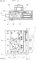
- a horizontal locking bolt 7 is provided which, in the first horizontal direction of movement, moves from a retracted position in the unlocked state ( Fig. 8 ), in which the horizontal locking bolt 7 essentially does not protrude beyond the locking housing 1, into a forward position in the locked state ( Fig. 9 ), in which the horizontal locking bolt 7 with a free end 71 protrudes significantly beyond the locking housing 1 and engages laterally into an opening in the corner fitting of the gooseneck container.
- Fig. 10 to 14 The exact mode of operation and the required components of the container locking device are described in the Fig. 10 to 14 in a side view (each for part figure a), a plan view (each for part figure b) of the container locking device and a cross-section (each for part figure c).
- Fig. 10 The container locking device is shown in its unlocked state, in which a container can be unloaded or loaded.
- a container can be unloaded or loaded.
- the locking bolt 2 with its shaft 20 is in an elevated position, i.e. axially displaced upwards, and the locking head 21 belonging to the locking bolt 2 rests on the guide component 11, as can be seen in particular from Fig. 10a can be seen.
- a container with its corner fitting and its slot-like opening formed therein can be loaded onto the loading surface and in particular onto the load-bearing surface 12 via the locking head 21 and the guide component 11 or lifted from the loaded position, since the locking head 21 is aligned with the guide component 11 (see top view).
- Fig. 10b the horizontal locking bolt 7 is in its retracted position, in which the horizontal locking bolt 7 does not protrude significantly beyond the locking housing 1.
- the drive 3 can be seen in the form of a double-acting pneumatic cylinder 30, which is arranged in the drive box 10 of the locking housing 1.
- the double-acting pneumatic cylinder 30 has a piston rod 31, which interacts via a drive claw 32 with a wedge slide 4 that can be moved back and forth in the drive box 10 parallel to the pneumatic cylinder 30 via a first driver 41.
- a first driver 41 With regard to the design of the wedge slide 4 and its operative connection to the locking bolt 2, reference is made to the as yet unpublished DE 10 2021 112 894 of the same applicant. How the required rotational movement of the shaft 20 and thus of the locking head 21 is realized is shown in the sectional view Fig. 10c visible.
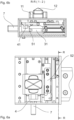
- the piston rod 31 with the drive claw 32 initially moves from the Fig. 10b shown position in the plane of the drawing to the left, as compared with Fig. 10b
- the first driver 41 is driven by the drive claw 32, whereby the wedge slide 4 connected to the first driver 41 also moves in the plane of the drawing according to Fig. 10b to the left.
- a second driver 42 is formed or attached to the wedge slide 4, which moves a wedge slide 8 on the locking housing 1 in the same first horizontal direction of movement (H 1 ), i.e. in Fig. 10b and 11b to the left.
- An actuating bevel (81) formed on the wedge slide (8) interacts with a bearing surface (72) on the horizontal locking bolt 7, whereby the latter moves in a second horizontal direction of movement (H 2 ) 90° to the first horizontal direction of movement (H 1 ) and, as can be seen from Fig. 11b visible, already protrudes significantly beyond the locking housing 1. Parallel to this, the shaft 20 of the locking bolt 2 rotates and thus also begins to move towards the locked state.
- Fig. 12 the locked state is then reached, in which the locking head 21 is now rotated by 90 ° and lowered between the guide component 11 (see Fig. 12a and 12b ). Parallel to this, the horizontal locking bolt 7 can also be seen with its free end 71 projecting far in its locked state.
- the wedge slide (4) and thus the wedge slide (8) slide out in the plane of the drawing according to Fig. 12 all the way to the left, the bearing surface (72) of the horizontal locking bolt 7 along the actuating bevel (81) of the wedge slide (8) to its outer edge, until the bearing surface (72) of the horizontal locking bolt 7 rests on the support surface (82) of the actuating bevel (81) (see Fig. 12c ).
- a locking device 5 which is arranged in the drive box 10 of the locking housing 1 and has a lock 51 which is applied to the drive claw 32 or the driver 41 by means of a leaf spring 52, so that when the end position is reached in the locked state ( Fig. 12b ) engages in the path of the wedge slide 4, namely behind the driver 41, where it forms a positive lock against an undesired release (resetting) of the locking mechanism.
- a short first idle stroke of the piston rod 31 takes place, during which the drive claw 32 moves from its first driver 41 in the plane of the drawing from Fig. 11b to the left pushing position in which the first driver 41 in the plane of the drawing of Fig. 13b to the right pulling position and comes into contact with a displacement component 53 of the locking device 5 by means of a release projection 33 on the drive claw 32.
- a second idle stroke is carried out between the second driver (42) and the wedge slide (8), so that the return movement of the wedge slide (8) in Fig. 13c opposite to the first horizontal direction of movement (H 1 ) just begins and the positive engagement of the bearing surface (72) of the horizontal locking bolt 7 on the support surface (82) is released.
- the release projection 33 on the drive claw 32 via the displacement component 53 of the locking device 5 the lock 51 against the force of the leaf spring 52 from the path of movement of the first driver 41 (in the plane of the drawing of the Fig. 13b and 14b upwards), whereby the first driver 41 and thus the wedge slide 4 in the drive box 10 is released and the first driver 41 prevents the lock 51 loaded by the leaf spring 52 from springing back.
- the locking bolt 2 is raised completely in the axial direction so that the projections of the locking head 21 are above the guide component 11 ( Fig. 14a ) and then the locking head 21 can be turned back.
- the horizontal locking bolt 7 is then also retracted with the parallel return movement of the wedge slide (8) via the actuating slope (81) of the wedge slide (8), so that the unlocked state is then restored according to Fig. 10 Accordingly, the locking bolt 2 rotates back into its unlocked state so that the locking head 21 is flush with the guide component 11, as shown in Fig. 10b shown in top view (unlocked state).
Landscapes
- Engineering & Computer Science (AREA)
- Transportation (AREA)
- Mechanical Engineering (AREA)
- Lock And Its Accessories (AREA)
- Fittings On The Vehicle Exterior For Carrying Loads, And Devices For Holding Or Mounting Articles (AREA)
- Load-Engaging Elements For Cranes (AREA)
Applications Claiming Priority (3)
| Application Number | Priority Date | Filing Date | Title |
|---|---|---|---|
| DE102021116280.7A DE102021116280A1 (de) | 2021-06-23 | 2021-06-23 | Containerverriegelungsvorrichtung sowie Containerverriegelungsverfahren |
| DE102021122625.2A DE102021122625A1 (de) | 2021-09-01 | 2021-09-01 | Containerverriegelungsvorrichtung sowie Containerverriegelungsverfahren |
| PCT/DE2022/100442 WO2022268257A1 (de) | 2021-06-23 | 2022-06-14 | Containerverriegelungsvorrichtung sowie containerverriegelungsverfahren |
Publications (2)
| Publication Number | Publication Date |
|---|---|
| EP4359256A1 EP4359256A1 (de) | 2024-05-01 |
| EP4359256B1 true EP4359256B1 (de) | 2025-01-22 |
Family
ID=82358609
Family Applications (1)
| Application Number | Title | Priority Date | Filing Date |
|---|---|---|---|
| EP22735767.0A Active EP4359256B1 (de) | 2021-06-23 | 2022-06-14 | Containerverriegelungsvorrichtung sowie containerverriegelungsverfahren |
Country Status (6)
| Country | Link |
|---|---|
| US (1) | US20240262283A1 (pl) |
| EP (1) | EP4359256B1 (pl) |
| KR (1) | KR102902513B1 (pl) |
| CA (1) | CA3222443A1 (pl) |
| PL (1) | PL4359256T3 (pl) |
| WO (1) | WO2022268257A1 (pl) |
Families Citing this family (2)
| Publication number | Priority date | Publication date | Assignee | Title |
|---|---|---|---|---|
| WO2025213225A1 (en) * | 2024-04-11 | 2025-10-16 | The Dynamic Engineering Solution Pty Ltd | Load securing device |
| CN119840963A (zh) * | 2025-02-28 | 2025-04-18 | 北京工业大学 | 一种基于柔性铰链的双向自锁楔块快速装配和拆卸机构 |
Family Cites Families (17)
| Publication number | Priority date | Publication date | Assignee | Title |
|---|---|---|---|---|
| US5575599A (en) | 1994-04-15 | 1996-11-19 | Penz Products, Inc. | Container lock pin system |
| DE19720238A1 (de) | 1997-05-14 | 1998-11-19 | Frank P Schulz | Verriegelung für Container an einem Fahrzeugchassis |
| DE19804771C2 (de) | 1998-02-06 | 2000-06-15 | Schneider Fahrzeug Und Contain | Verriegelungsvorrichtung für Container-Transportfahrzeuge |
| DE29903940U1 (de) | 1999-03-04 | 1999-09-09 | R. Metternich Metallbau GmbH, 21107 Hamburg | Verriegelungseinrichtung für Container auf dem Chassis eines Fahrzeuges |
| KR200186762Y1 (ko) * | 2000-01-27 | 2000-06-15 | 김용락 | 트레일러용 컨테이너의 자동 록킹장치 |
| DE10202190B4 (de) | 2002-01-22 | 2006-10-19 | Jost-Werke Gmbh & Co. Kg | Container-Verriegelungsvorrichtung |
| KR100460466B1 (ko) * | 2002-06-25 | 2004-12-14 | (주)파크랜드 | 트레일러 적재용 컨테이너의 자동 록킹장치 |
| DE102004045665B4 (de) | 2004-09-18 | 2008-01-31 | Jost-Werke Gmbh & Co. Kg | Querträger zum stirnseitigen Einbau in ein Chassis |
| DE102006002654A1 (de) | 2006-01-19 | 2007-08-23 | Rmm Entwicklungsgesellschaft Mbh & Co.Kg | Vorrichtung zur Betätigung einer Verriegelung eines Verriegelungskopfes mit einem Eckbeschlag eines Containers |
| DE202008011526U1 (de) | 2008-08-29 | 2009-12-31 | Bermüller, Wolfgang | Vorrichtung zum Festlegen des CC eines Containers |
| JP5468335B2 (ja) | 2009-09-04 | 2014-04-09 | 日本トレクス株式会社 | コンテナ積載用セミトレーラ |
| DE202010000387U1 (de) | 2010-03-16 | 2010-06-02 | 1. Rmm Entwicklungsgesellschaft Mbh & Co. Kg | Horizontalverriegelungsvorrichtung zur Verriegelung eines Containers mit Eckbeschlag auf einer Ladefläche |
| US9463732B2 (en) | 2014-02-19 | 2016-10-11 | Mi-Jack Products, Inc. | Latching system for automatic securement of a container to a container chassis |
| KR101507925B1 (ko) | 2014-09-19 | 2015-04-07 | 주식회사 케이지에스 | 컨테이너 하부지지대 |
| DE102014218891A1 (de) | 2014-09-19 | 2016-03-24 | Jost-Werke Gmbh | Verriegelungsvorrichtung für Container |
| DE202018107146U1 (de) * | 2018-12-14 | 2020-03-23 | Kögel Trailer GmbH | Containerverriegelung, Frontausschub eines Fahrgestells mit einer solchen Containerverriegelung, Fahrgestell und Verriegelungsanordnung |
| KR102340301B1 (ko) * | 2020-01-28 | 2021-12-15 | 전형율 | 컨테이너 자동 잠금장치 |
-
2022
- 2022-06-14 PL PL22735767.0T patent/PL4359256T3/pl unknown
- 2022-06-14 WO PCT/DE2022/100442 patent/WO2022268257A1/de not_active Ceased
- 2022-06-14 EP EP22735767.0A patent/EP4359256B1/de active Active
- 2022-06-14 US US18/567,704 patent/US20240262283A1/en active Pending
- 2022-06-14 KR KR1020247002312A patent/KR102902513B1/ko active Active
- 2022-06-14 CA CA3222443A patent/CA3222443A1/en active Pending
Also Published As
| Publication number | Publication date |
|---|---|
| KR102902513B1 (ko) | 2025-12-18 |
| PL4359256T3 (pl) | 2025-04-28 |
| WO2022268257A1 (de) | 2022-12-29 |
| US20240262283A1 (en) | 2024-08-08 |
| EP4359256A1 (de) | 2024-05-01 |
| CA3222443A1 (en) | 2022-12-29 |
| KR20240024227A (ko) | 2024-02-23 |
Similar Documents
| Publication | Publication Date | Title |
|---|---|---|
| EP2864222B1 (de) | Verriegelungsvorrichtungsanordnung | |
| EP2585341B1 (de) | Verriegelungsvorrichtung für container | |
| EP4341129B1 (de) | Containerverriegelungsvorrichtung sowie containerverriegelungsverfahren | |
| EP4359256B1 (de) | Containerverriegelungsvorrichtung sowie containerverriegelungsverfahren | |
| DE202009016268U1 (de) | Verriegelungsvorrichtung für Container | |
| EP4351925B1 (de) | Absenkbare containerverriegelung | |
| EP3528955B1 (de) | Selbstverriegelnder aufgabetrichter | |
| WO2010149180A1 (de) | Riegelelement | |
| EP1661755B1 (de) | Lastentransportfahrzeug, insbesondere Absetzkipper | |
| DE102021116280A1 (de) | Containerverriegelungsvorrichtung sowie Containerverriegelungsverfahren | |
| DE202011050490U1 (de) | Horizontalverriegelungsvorrichtung | |
| DE102021122625A1 (de) | Containerverriegelungsvorrichtung sowie Containerverriegelungsverfahren | |
| DE3048652C2 (de) | Handbetätigungsanordnung für Frachtladesysteme | |
| DE1605012C3 (de) | Fahrzeug, insbesondere Eisenbahnwagen mit aufklappbarem Dach | |
| EP4001006B1 (de) | Vorrichtung zur verriegelung einer behälterklappe | |
| EP0698545A1 (de) | Doppelstockwagen | |
| EP4489995A1 (de) | Anhebe- und absenkanordnung für containerverriegelung und anhebe- und absenkverfahren damit | |
| EP4450447B1 (de) | Mobilkran-abstützung mit feststelleinrichtung | |
| DE102006034666B4 (de) | Überladebrücke mit Sicherheitsspere und Verfahren zum Betreiben der Überladebrücke | |
| DE202010006591U1 (de) | Transportmittel mit Hubboden und Schubelement | |
| EP4397575A1 (de) | Nutzfahrzeug mit beweglichem heckausschub | |
| WO2001079081A1 (de) | Verriegelungsmechanismus für behälter, insbesondere container | |
| DE2343251C3 (de) | Vorrichtung zum Verriegeln eines Frachtbehälters auf einem Untersatz, insbesondere einem Fahrgestell | |
| DE2410771A1 (de) | Vorrichtung zum verriegeln eines frachtbehaelters auf einem untersatz, insbesondere einem fahrgestell | |
| EP1518768A1 (de) | Vorrichtung zum Abstützen von Plattformen |
Legal Events
| Date | Code | Title | Description |
|---|---|---|---|
| STAA | Information on the status of an ep patent application or granted ep patent |
Free format text: STATUS: UNKNOWN |
|
| STAA | Information on the status of an ep patent application or granted ep patent |
Free format text: STATUS: THE INTERNATIONAL PUBLICATION HAS BEEN MADE |
|
| PUAI | Public reference made under article 153(3) epc to a published international application that has entered the european phase |
Free format text: ORIGINAL CODE: 0009012 |
|
| STAA | Information on the status of an ep patent application or granted ep patent |
Free format text: STATUS: REQUEST FOR EXAMINATION WAS MADE |
|
| 17P | Request for examination filed |
Effective date: 20231229 |
|
| AK | Designated contracting states |
Kind code of ref document: A1 Designated state(s): AL AT BE BG CH CY CZ DE DK EE ES FI FR GB GR HR HU IE IS IT LI LT LU LV MC MK MT NL NO PL PT RO RS SE SI SK SM TR |
|
| GRAP | Despatch of communication of intention to grant a patent |
Free format text: ORIGINAL CODE: EPIDOSNIGR1 |
|
| STAA | Information on the status of an ep patent application or granted ep patent |
Free format text: STATUS: GRANT OF PATENT IS INTENDED |
|
| DAV | Request for validation of the european patent (deleted) | ||
| DAX | Request for extension of the european patent (deleted) | ||
| INTG | Intention to grant announced |
Effective date: 20240826 |
|
| GRAJ | Information related to disapproval of communication of intention to grant by the applicant or resumption of examination proceedings by the epo deleted |
Free format text: ORIGINAL CODE: EPIDOSDIGR1 |
|
| GRAP | Despatch of communication of intention to grant a patent |
Free format text: ORIGINAL CODE: EPIDOSNIGR1 |
|
| INTG | Intention to grant announced |
Effective date: 20241106 |
|
| GRAS | Grant fee paid |
Free format text: ORIGINAL CODE: EPIDOSNIGR3 |
|
| GRAA | (expected) grant |
Free format text: ORIGINAL CODE: 0009210 |
|
| STAA | Information on the status of an ep patent application or granted ep patent |
Free format text: STATUS: THE PATENT HAS BEEN GRANTED |
|
| AK | Designated contracting states |
Kind code of ref document: B1 Designated state(s): AL AT BE BG CH CY CZ DE DK EE ES FI FR GB GR HR HU IE IS IT LI LT LU LV MC MK MT NL NO PL PT RO RS SE SI SK SM TR |
|
| REG | Reference to a national code |
Ref country code: GB Ref legal event code: FG4D Free format text: NOT ENGLISH |
|
| REG | Reference to a national code |
Ref country code: CH Ref legal event code: EP |
|
| REG | Reference to a national code |
Ref country code: IE Ref legal event code: FG4D Free format text: LANGUAGE OF EP DOCUMENT: GERMAN |
|
| REG | Reference to a national code |
Ref country code: DE Ref legal event code: R096 Ref document number: 502022002730 Country of ref document: DE |
|
| REG | Reference to a national code |
Ref country code: NL Ref legal event code: FP |
|
| PG25 | Lapsed in a contracting state [announced via postgrant information from national office to epo] |
Ref country code: RS Free format text: LAPSE BECAUSE OF FAILURE TO SUBMIT A TRANSLATION OF THE DESCRIPTION OR TO PAY THE FEE WITHIN THE PRESCRIBED TIME-LIMIT Effective date: 20250422 |
|
| PG25 | Lapsed in a contracting state [announced via postgrant information from national office to epo] |
Ref country code: FI Free format text: LAPSE BECAUSE OF FAILURE TO SUBMIT A TRANSLATION OF THE DESCRIPTION OR TO PAY THE FEE WITHIN THE PRESCRIBED TIME-LIMIT Effective date: 20250122 |
|
| PGFP | Annual fee paid to national office [announced via postgrant information from national office to epo] |
Ref country code: PL Payment date: 20250529 Year of fee payment: 4 Ref country code: DE Payment date: 20250618 Year of fee payment: 4 |
|
| PG25 | Lapsed in a contracting state [announced via postgrant information from national office to epo] |
Ref country code: ES Free format text: LAPSE BECAUSE OF FAILURE TO SUBMIT A TRANSLATION OF THE DESCRIPTION OR TO PAY THE FEE WITHIN THE PRESCRIBED TIME-LIMIT Effective date: 20250122 |
|
| REG | Reference to a national code |
Ref country code: LT Ref legal event code: MG9D |
|
| PG25 | Lapsed in a contracting state [announced via postgrant information from national office to epo] |
Ref country code: IS Free format text: LAPSE BECAUSE OF FAILURE TO SUBMIT A TRANSLATION OF THE DESCRIPTION OR TO PAY THE FEE WITHIN THE PRESCRIBED TIME-LIMIT Effective date: 20250522 Ref country code: NO Free format text: LAPSE BECAUSE OF FAILURE TO SUBMIT A TRANSLATION OF THE DESCRIPTION OR TO PAY THE FEE WITHIN THE PRESCRIBED TIME-LIMIT Effective date: 20250422 |
|
| PGFP | Annual fee paid to national office [announced via postgrant information from national office to epo] |
Ref country code: NL Payment date: 20250618 Year of fee payment: 4 |
|
| PG25 | Lapsed in a contracting state [announced via postgrant information from national office to epo] |
Ref country code: HR Free format text: LAPSE BECAUSE OF FAILURE TO SUBMIT A TRANSLATION OF THE DESCRIPTION OR TO PAY THE FEE WITHIN THE PRESCRIBED TIME-LIMIT Effective date: 20250122 |
|
| PG25 | Lapsed in a contracting state [announced via postgrant information from national office to epo] |
Ref country code: LV Free format text: LAPSE BECAUSE OF FAILURE TO SUBMIT A TRANSLATION OF THE DESCRIPTION OR TO PAY THE FEE WITHIN THE PRESCRIBED TIME-LIMIT Effective date: 20250122 Ref country code: PT Free format text: LAPSE BECAUSE OF FAILURE TO SUBMIT A TRANSLATION OF THE DESCRIPTION OR TO PAY THE FEE WITHIN THE PRESCRIBED TIME-LIMIT Effective date: 20250522 |
|
| PGFP | Annual fee paid to national office [announced via postgrant information from national office to epo] |
Ref country code: FR Payment date: 20250626 Year of fee payment: 4 |
|
| PG25 | Lapsed in a contracting state [announced via postgrant information from national office to epo] |
Ref country code: BG Free format text: LAPSE BECAUSE OF FAILURE TO SUBMIT A TRANSLATION OF THE DESCRIPTION OR TO PAY THE FEE WITHIN THE PRESCRIBED TIME-LIMIT Effective date: 20250122 Ref country code: GR Free format text: LAPSE BECAUSE OF FAILURE TO SUBMIT A TRANSLATION OF THE DESCRIPTION OR TO PAY THE FEE WITHIN THE PRESCRIBED TIME-LIMIT Effective date: 20250423 |
|
| PGFP | Annual fee paid to national office [announced via postgrant information from national office to epo] |
Ref country code: AT Payment date: 20250721 Year of fee payment: 4 |
|
| PGFP | Annual fee paid to national office [announced via postgrant information from national office to epo] |
Ref country code: TR Payment date: 20250612 Year of fee payment: 4 |
|
| PG25 | Lapsed in a contracting state [announced via postgrant information from national office to epo] |
Ref country code: SE Free format text: LAPSE BECAUSE OF FAILURE TO SUBMIT A TRANSLATION OF THE DESCRIPTION OR TO PAY THE FEE WITHIN THE PRESCRIBED TIME-LIMIT Effective date: 20250122 |
|
| PG25 | Lapsed in a contracting state [announced via postgrant information from national office to epo] |
Ref country code: SM Free format text: LAPSE BECAUSE OF FAILURE TO SUBMIT A TRANSLATION OF THE DESCRIPTION OR TO PAY THE FEE WITHIN THE PRESCRIBED TIME-LIMIT Effective date: 20250122 |
|
| PG25 | Lapsed in a contracting state [announced via postgrant information from national office to epo] |
Ref country code: DK Free format text: LAPSE BECAUSE OF FAILURE TO SUBMIT A TRANSLATION OF THE DESCRIPTION OR TO PAY THE FEE WITHIN THE PRESCRIBED TIME-LIMIT Effective date: 20250122 |
|
| PG25 | Lapsed in a contracting state [announced via postgrant information from national office to epo] |
Ref country code: IT Free format text: LAPSE BECAUSE OF FAILURE TO SUBMIT A TRANSLATION OF THE DESCRIPTION OR TO PAY THE FEE WITHIN THE PRESCRIBED TIME-LIMIT Effective date: 20250122 |
|
| PG25 | Lapsed in a contracting state [announced via postgrant information from national office to epo] |
Ref country code: CZ Free format text: LAPSE BECAUSE OF FAILURE TO SUBMIT A TRANSLATION OF THE DESCRIPTION OR TO PAY THE FEE WITHIN THE PRESCRIBED TIME-LIMIT Effective date: 20250122 Ref country code: EE Free format text: LAPSE BECAUSE OF FAILURE TO SUBMIT A TRANSLATION OF THE DESCRIPTION OR TO PAY THE FEE WITHIN THE PRESCRIBED TIME-LIMIT Effective date: 20250122 |
|
| REG | Reference to a national code |
Ref country code: DE Ref legal event code: R097 Ref document number: 502022002730 Country of ref document: DE |
|
| PG25 | Lapsed in a contracting state [announced via postgrant information from national office to epo] |
Ref country code: RO Free format text: LAPSE BECAUSE OF FAILURE TO SUBMIT A TRANSLATION OF THE DESCRIPTION OR TO PAY THE FEE WITHIN THE PRESCRIBED TIME-LIMIT Effective date: 20250122 |
|
| PG25 | Lapsed in a contracting state [announced via postgrant information from national office to epo] |
Ref country code: SK Free format text: LAPSE BECAUSE OF FAILURE TO SUBMIT A TRANSLATION OF THE DESCRIPTION OR TO PAY THE FEE WITHIN THE PRESCRIBED TIME-LIMIT Effective date: 20250122 |
|
| PLBE | No opposition filed within time limit |
Free format text: ORIGINAL CODE: 0009261 |
|
| STAA | Information on the status of an ep patent application or granted ep patent |
Free format text: STATUS: NO OPPOSITION FILED WITHIN TIME LIMIT |
|
| REG | Reference to a national code |
Ref country code: CH Ref legal event code: L10 Free format text: ST27 STATUS EVENT CODE: U-0-0-L10-L00 (AS PROVIDED BY THE NATIONAL OFFICE) Effective date: 20251203 |
|
| 26N | No opposition filed |
Effective date: 20251023 |
|
| REG | Reference to a national code |
Ref country code: CH Ref legal event code: H13 Free format text: ST27 STATUS EVENT CODE: U-0-0-H10-H13 (AS PROVIDED BY THE NATIONAL OFFICE) Effective date: 20260127 |
|
| PG25 | Lapsed in a contracting state [announced via postgrant information from national office to epo] |
Ref country code: MC Free format text: LAPSE BECAUSE OF FAILURE TO SUBMIT A TRANSLATION OF THE DESCRIPTION OR TO PAY THE FEE WITHIN THE PRESCRIBED TIME-LIMIT Effective date: 20250122 |