EP4357631A1 - Radlagervorrichtung - Google Patents
Radlagervorrichtung Download PDFInfo
- Publication number
- EP4357631A1 EP4357631A1 EP22824872.0A EP22824872A EP4357631A1 EP 4357631 A1 EP4357631 A1 EP 4357631A1 EP 22824872 A EP22824872 A EP 22824872A EP 4357631 A1 EP4357631 A1 EP 4357631A1
- Authority
- EP
- European Patent Office
- Prior art keywords
- diameter side
- outer diameter
- recess portion
- vehicle wheel
- hub
- Prior art date
- Legal status (The legal status is an assumption and is not a legal conclusion. Google has not performed a legal analysis and makes no representation as to the accuracy of the status listed.)
- Pending
Links
Images


Classifications
-
- F—MECHANICAL ENGINEERING; LIGHTING; HEATING; WEAPONS; BLASTING
- F16—ENGINEERING ELEMENTS AND UNITS; GENERAL MEASURES FOR PRODUCING AND MAINTAINING EFFECTIVE FUNCTIONING OF MACHINES OR INSTALLATIONS; THERMAL INSULATION IN GENERAL
- F16C—SHAFTS; FLEXIBLE SHAFTS; ELEMENTS OR CRANKSHAFT MECHANISMS; ROTARY BODIES OTHER THAN GEARING ELEMENTS; BEARINGS
- F16C19/00—Bearings with rolling contact, for exclusively rotary movement
- F16C19/02—Bearings with rolling contact, for exclusively rotary movement with bearing balls essentially of the same size in one or more circular rows
- F16C19/14—Bearings with rolling contact, for exclusively rotary movement with bearing balls essentially of the same size in one or more circular rows for both radial and axial load
- F16C19/18—Bearings with rolling contact, for exclusively rotary movement with bearing balls essentially of the same size in one or more circular rows for both radial and axial load with two or more rows of balls
- F16C19/181—Bearings with rolling contact, for exclusively rotary movement with bearing balls essentially of the same size in one or more circular rows for both radial and axial load with two or more rows of balls with angular contact
- F16C19/183—Bearings with rolling contact, for exclusively rotary movement with bearing balls essentially of the same size in one or more circular rows for both radial and axial load with two or more rows of balls with angular contact with two rows at opposite angles
- F16C19/184—Bearings with rolling contact, for exclusively rotary movement with bearing balls essentially of the same size in one or more circular rows for both radial and axial load with two or more rows of balls with angular contact with two rows at opposite angles in O-arrangement
- F16C19/186—Bearings with rolling contact, for exclusively rotary movement with bearing balls essentially of the same size in one or more circular rows for both radial and axial load with two or more rows of balls with angular contact with two rows at opposite angles in O-arrangement with three raceways provided integrally on parts other than race rings, e.g. third generation hubs
-
- B—PERFORMING OPERATIONS; TRANSPORTING
- B60—VEHICLES IN GENERAL
- B60B—VEHICLE WHEELS; CASTORS; AXLES FOR WHEELS OR CASTORS; INCREASING WHEEL ADHESION
- B60B27/00—Hubs
- B60B27/0005—Hubs with ball bearings
-
- B—PERFORMING OPERATIONS; TRANSPORTING
- B60—VEHICLES IN GENERAL
- B60B—VEHICLE WHEELS; CASTORS; AXLES FOR WHEELS OR CASTORS; INCREASING WHEEL ADHESION
- B60B27/00—Hubs
- B60B27/0073—Hubs characterised by sealing means
-
- B—PERFORMING OPERATIONS; TRANSPORTING
- B60—VEHICLES IN GENERAL
- B60B—VEHICLE WHEELS; CASTORS; AXLES FOR WHEELS OR CASTORS; INCREASING WHEEL ADHESION
- B60B27/00—Hubs
- B60B27/0078—Hubs characterised by the fixation of bearings
-
- B—PERFORMING OPERATIONS; TRANSPORTING
- B60—VEHICLES IN GENERAL
- B60B—VEHICLE WHEELS; CASTORS; AXLES FOR WHEELS OR CASTORS; INCREASING WHEEL ADHESION
- B60B27/00—Hubs
- B60B27/0078—Hubs characterised by the fixation of bearings
- B60B27/0084—Hubs characterised by the fixation of bearings caulking to fix inner race
-
- B—PERFORMING OPERATIONS; TRANSPORTING
- B60—VEHICLES IN GENERAL
- B60B—VEHICLE WHEELS; CASTORS; AXLES FOR WHEELS OR CASTORS; INCREASING WHEEL ADHESION
- B60B27/00—Hubs
- B60B27/0094—Hubs one or more of the bearing races are formed by the hub
-
- F—MECHANICAL ENGINEERING; LIGHTING; HEATING; WEAPONS; BLASTING
- F16—ENGINEERING ELEMENTS AND UNITS; GENERAL MEASURES FOR PRODUCING AND MAINTAINING EFFECTIVE FUNCTIONING OF MACHINES OR INSTALLATIONS; THERMAL INSULATION IN GENERAL
- F16C—SHAFTS; FLEXIBLE SHAFTS; ELEMENTS OR CRANKSHAFT MECHANISMS; ROTARY BODIES OTHER THAN GEARING ELEMENTS; BEARINGS
- F16C33/00—Parts of bearings; Special methods for making bearings or parts thereof
- F16C33/72—Sealings
- F16C33/76—Sealings of ball or roller bearings
- F16C33/78—Sealings of ball or roller bearings with a diaphragm, disc, or ring, with or without resilient members
- F16C33/7869—Sealings of ball or roller bearings with a diaphragm, disc, or ring, with or without resilient members mounted with a cylindrical portion to the inner surface of the outer race and having a radial portion extending inward
- F16C33/7873—Sealings of ball or roller bearings with a diaphragm, disc, or ring, with or without resilient members mounted with a cylindrical portion to the inner surface of the outer race and having a radial portion extending inward with a single sealing ring of generally L-shaped cross-section
- F16C33/7876—Sealings of ball or roller bearings with a diaphragm, disc, or ring, with or without resilient members mounted with a cylindrical portion to the inner surface of the outer race and having a radial portion extending inward with a single sealing ring of generally L-shaped cross-section with sealing lips
-
- F—MECHANICAL ENGINEERING; LIGHTING; HEATING; WEAPONS; BLASTING
- F16—ENGINEERING ELEMENTS AND UNITS; GENERAL MEASURES FOR PRODUCING AND MAINTAINING EFFECTIVE FUNCTIONING OF MACHINES OR INSTALLATIONS; THERMAL INSULATION IN GENERAL
- F16C—SHAFTS; FLEXIBLE SHAFTS; ELEMENTS OR CRANKSHAFT MECHANISMS; ROTARY BODIES OTHER THAN GEARING ELEMENTS; BEARINGS
- F16C33/00—Parts of bearings; Special methods for making bearings or parts thereof
- F16C33/72—Sealings
- F16C33/76—Sealings of ball or roller bearings
- F16C33/80—Labyrinth sealings
- F16C33/805—Labyrinth sealings in addition to other sealings, e.g. dirt guards to protect sealings with sealing lips
-
- F—MECHANICAL ENGINEERING; LIGHTING; HEATING; WEAPONS; BLASTING
- F16—ENGINEERING ELEMENTS AND UNITS; GENERAL MEASURES FOR PRODUCING AND MAINTAINING EFFECTIVE FUNCTIONING OF MACHINES OR INSTALLATIONS; THERMAL INSULATION IN GENERAL
- F16J—PISTONS; CYLINDERS; SEALINGS
- F16J15/00—Sealings
- F16J15/16—Sealings between relatively-moving surfaces
- F16J15/32—Sealings between relatively-moving surfaces with elastic sealings, e.g. O-rings
- F16J15/3204—Sealings between relatively-moving surfaces with elastic sealings, e.g. O-rings with at least one lip
- F16J15/3232—Sealings between relatively-moving surfaces with elastic sealings, e.g. O-rings with at least one lip having two or more lips
-
- F—MECHANICAL ENGINEERING; LIGHTING; HEATING; WEAPONS; BLASTING
- F16—ENGINEERING ELEMENTS AND UNITS; GENERAL MEASURES FOR PRODUCING AND MAINTAINING EFFECTIVE FUNCTIONING OF MACHINES OR INSTALLATIONS; THERMAL INSULATION IN GENERAL
- F16J—PISTONS; CYLINDERS; SEALINGS
- F16J15/00—Sealings
- F16J15/16—Sealings between relatively-moving surfaces
- F16J15/32—Sealings between relatively-moving surfaces with elastic sealings, e.g. O-rings
- F16J15/328—Manufacturing methods specially adapted for elastic sealings
-
- F—MECHANICAL ENGINEERING; LIGHTING; HEATING; WEAPONS; BLASTING
- F16—ENGINEERING ELEMENTS AND UNITS; GENERAL MEASURES FOR PRODUCING AND MAINTAINING EFFECTIVE FUNCTIONING OF MACHINES OR INSTALLATIONS; THERMAL INSULATION IN GENERAL
- F16J—PISTONS; CYLINDERS; SEALINGS
- F16J15/00—Sealings
- F16J15/44—Free-space packings
- F16J15/447—Labyrinth packings
- F16J15/4476—Labyrinth packings with radial path
-
- B—PERFORMING OPERATIONS; TRANSPORTING
- B60—VEHICLES IN GENERAL
- B60B—VEHICLE WHEELS; CASTORS; AXLES FOR WHEELS OR CASTORS; INCREASING WHEEL ADHESION
- B60B2380/00—Bearings
- B60B2380/10—Type
- B60B2380/12—Ball bearings
-
- F—MECHANICAL ENGINEERING; LIGHTING; HEATING; WEAPONS; BLASTING
- F16—ENGINEERING ELEMENTS AND UNITS; GENERAL MEASURES FOR PRODUCING AND MAINTAINING EFFECTIVE FUNCTIONING OF MACHINES OR INSTALLATIONS; THERMAL INSULATION IN GENERAL
- F16C—SHAFTS; FLEXIBLE SHAFTS; ELEMENTS OR CRANKSHAFT MECHANISMS; ROTARY BODIES OTHER THAN GEARING ELEMENTS; BEARINGS
- F16C2326/00—Articles relating to transporting
- F16C2326/01—Parts of vehicles in general
- F16C2326/02—Wheel hubs or castors
Definitions
- the present invention relates to a bearing device for vehicle wheel.
- a bearing device for vehicle wheel rotatably supporting a vehicle wheel in a suspension device of an automobile or the like.
- the bearing device for vehicle wheel is provided with a sealing device that closes an opening end of an annular space formed by an outer member and an inner member to prevent entry of foreign matters such as muddy water.
- a hub ring which is an inner member, has a hub flange extending radially outward, a sliding face on which a main lip of a sealing device is in sliding contact is formed at a base end portion of the hub flange, and a recess portion is formed on an outer diameter side relative to the sliding face of the hub flange.
- a side lip of the sealing device contactlessly faces the recess portion of the hub flange, and a labyrinth seal is formed by the recess portion and the side lip, thereby improving mud water resistance of the sealing device.
- a flange face and the recess portion positioned on the outer diameter side relative to the recess portion in the hub flange are formed by turning, and the sliding face is formed by grinding.
- Patent Literature 1 JP-A 2013-61048 Gazette
- the recess portion has a U-shape and an outer diameter side edge portion of the recess portion is formed on a face perpendicular to the radial direction, when the hub flange is ground from the outer diameter side toward the inner diameter side, a turning tool for turning the flange face is less likely to enter an outer peripheral side portion of the recess portion from the outer diameter side.
- the present invention has been made in view of the above circumstances, and it is an object of the present invention to provide a bearing device for vehicle wheel that, when performing turning on a hub flange, can continuously perform turning on a recess portion without replacing a turning tool after performing turning on an outer diameter side relative to the recess portion, and can simplify grinding work on a hub ring.
- a bearing device for vehicle wheel includes: an outer member having a double row outer raceway grooves on an inner periphery; an inner member including a hub ring having a hub flange extending radially outward at an axial one end portion and having a small diameter step portion extending axially on an outer periphery, and at least one inner ring press-fitted into the small diameter step portion of the hub ring, the inner member having a double row inner raceway grooves facing the double row outer raceway grooves; a double row rolling elements rollably accommodated between both raceway grooves of the outer member and the inner member; and a sealing device closing an opening end on an axial one end side of an annular space formed by the outer member and the inner member, in which the hub ring includes the inner raceway groove, a seal land portion positioned at a base end portion of the hub flange and the seal land portion with which the sealing device is in sliding contact, a recess portion positioned on an outer diameter side of the seal land portion in the hub
- grinding work of a hub ring can be simplified.
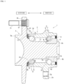
- a bearing device for a vehicle wheel 1 illustrated in FIG. 1 is an embodiment of a bearing device for vehicle wheel according to the present invention, and rotatably supports a vehicle wheel in a suspension device of a vehicle such as an automobile.
- the bearing device for a vehicle wheel 1 has a configuration called a third generation, and includes an outer ring 2, which is an outer member, a hub ring 3 and an inner ring 4, which are inner members, two rows of an inner side ball rows 5 and an outer side ball row 6, which are rolling rows, and an inner side seal member 9 and an outer side seal member 10.
- the inner side represents the vehicle body side of the bearing device for a vehicle wheel 1 when mounted to the vehicle body
- the outer side represents the vehicle wheel side of the bearing device for a vehicle wheel 1 when mounted to the vehicle body.
- the axial represents a direction along a rotation axis of the bearing device for a vehicle wheel 1, and the axial one end side is the outer side and the axial other end side is the inner side.
- An inner side opening portion 2a into which the inner side seal member 9 can be fitted is formed at an inner side end portion of the outer ring 2.
- An outer side opening portion 2b into which the outer side seal member 10 can be fitted is formed at an outer side end portion of the outer ring 2.
- An outer raceway groove 2c on the inner side and an outer raceway groove 2d on the outer side are formed on an inner peripheral face of the outer ring 2.
- a vehicle body mounting flange 2e for mounting the outer ring 2 to a vehicle body side member is integrally formed on an outer peripheral face of the outer ring 2.
- the vehicle body mounting flange 2e is provided with a bolt hole 2g into which a fastening member (here, the bolt) for fastening the vehicle body side member and the outer ring 2 is inserted.
- a small diameter step portion 3a having a smaller diameter than the outer side end portion is formed at an inner side end portion of an outer peripheral face 3j of the hub ring 3.
- a shoulder portion 3e is formed at an outer side end portion of the small diameter step portion 3a of the hub ring 3.
- a vehicle wheel mounting flange 3b for mounting a vehicle wheel is integrally formed at an outer side end portion of the hub ring 3.
- a plurality of bolt holes 3f are formed in the vehicle wheel mounting flange 3b.
- a hub bolt 3i for fastening the hub ring 3 and the vehicle wheel or a brake component is press-fitted into the bolt hole 3f.
- the vehicle wheel mounting flange 3b is an example of the hub flange extending radially outward.
- the outer peripheral face 3j of the hub ring 3 is provided with an inner raceway groove 3c on the outer side so as to face the outer raceway groove 2d on the outer side of the outer ring 2. That is, on the outer side of the inner member, the inner raceway groove 3c is configured by the hub ring 3.
- the outer side seal member 10 is fitted to an outer side opening end of an annular space formed by the outer ring 2 and the hub ring 3, and closes the outer side opening end.
- the outer side seal member 10 is an example of the sealing device.
- a seal land portion 3d with which the outer side seal member 10 comes into sliding contact is formed at a base end portion on the inner side of the vehicle wheel mounting flange 3b.
- the inner raceway groove 3c is axially positioned adjacent to the inner side of the seal land portion 3d.
- the vehicle wheel mounting flange 3b includes a flange face 3k facing the inner side. The flange face 3k is positioned on the outer diameter side of the seal land portion 3d.
- a recess portion 3m is formed between the flange face 3k and the seal land portion 3d on a side face om the inner side of the vehicle wheel mounting flange 3b.
- the recess portion 3m is formed in a groove shape recessed from the side face on the inner side to the outer side of the vehicle wheel mounting flange 3b.
- the hub ring 3 includes an outer side end face 3g at an end portion on the outer side of the vehicle wheel mounting flange 3b.
- the small diameter step portion 3a of the hub ring 3 is provided with the inner ring 4.
- the inner ring 4 is fixed to the small diameter step portion 3a of the hub ring 3 by press fitting and crimping.
- the inner ring 4 applies preload to the inner side ball row 5 and the outer side ball row 6, which are rolling rows.
- the inner ring 4 includes an inner side end face 4b at the inner side end portion, and an outer side end face 4c at the outer side end portion.
- a crimped portion 3h crimped to the inner side end face 4b of the inner ring 4 is formed at an inner side end portion of the hub ring 3.
- the outer peripheral face of the inner ring 4 is provided with an inner raceway groove 4a on the inner side so as to face the outer raceway groove 2c on the inner side of the outer ring 2. That is, the inner raceway groove 4a is formed by the inner ring 4 on the inner side of the inner member.
- the inner side ball row 5 and the outer side ball row 6, which are rolling rows, are configured by holding a plurality of balls 7, which are rolling elements, by a cage 8.
- the inner side ball row 5 is rollably sandwiched between the inner raceway groove 4a of the inner ring 4 and the outer raceway groove 2c on the inner side of the outer ring 2.
- the outer side ball row 6 is rollably sandwiched between the inner raceway groove 3c of the hub ring 3 and the outer raceway groove 2d on the outer side of the outer ring 2. That is, the inner side ball row 5 and the outer side ball row 6 are rollably accommodated between the both raceway grooves of the outer member and the inner member.
- the outer ring 2, the hub ring 3, the inner ring 4, the inner side ball row 5, and the outer side ball row 6 constitute a double row angular ball bearing.
- the bearing device for a vehicle wheel 1 may constitute a double row tapered roller bearing instead of the double row angular ball bearing.
- the outer side seal member 10 includes a core metal 11 fitted to the inner periphery of the outer side end portion in the outer ring 2, and a seal member 12 integrally joined to the core metal 11.
- the core metal 11 is made of, for example, a steel plate, and includes a fitting portion 11a having a cylindrical shape fitted to the inner periphery of the outer side opening portion 2b of the outer ring 2, an inner portion 11b extending from the inner side end portion of the fitting portion 11a to the inner diameter side, an outer portion 11c extending from the outer side end portion of the fitting portion 11a to the outer diameter side, and an outer edge portion 11d extending from the outer diameter side end portion of the outer portion 11c to the inner side.
- the inner portion 11b is bent from the inner side end portion of the fitting portion 11a, extends to the outer side, then extends to the inner diameter side, further extends to the inner side and the inner diameter side, and then extends to the inner diameter side.
- the outer edge portion 11d extends to the inner side at a predetermined interval from the outer peripheral face 2h of the outer ring 2.
- the seal member 12 is made of, for example, an elastic member such as synthetic rubber, and is joined to the core metal 11 by vulcanization adhesion.
- the seal member 12 includes a base portion 12a, a radial lip 12b, a first contact lip 12c, a second contact lip 12d, a labyrinth lip 12e, and a weir portion 12f.
- the base portion 12a is joined in a range from the inner portion 11b of the core metal 11 to the outer edge portion 11d via the fitting portion 11a and the outer portion 11c.
- the radial lip 12b is positioned at the inner diameter side end portion of the seal member 12, and extends radially inward and toward the inner side from the inner portion 11b of the core metal 11.
- the radial lip 12b is in sliding contact with the outer peripheral face 3j of the hub ring 3 via an oil film of grease.
- the first contact lip 12c extends from the inner portion 11b of the core metal 11 toward the vehicle wheel mounting flange 3b side and radially outward on the outer diameter side relative to the radial lip 12b.
- the first contact lip 12c is in sliding contact with the seal land portion 3d via an oil film of grease.
- the first contact lip 12c is an example of the contact lip that comes into contact with the seal land portion 3d.
- the second contact lip 12d extends from the inner portion 11b of the core metal 11 toward the vehicle wheel mounting flange 3b side and radially outward on the outer diameter side relative to the first contact lip 12c.
- the second contact lip 12d is in sliding contact with the seal land portion 3d via an oil film of grease.
- the second contact lip 12d includes, on a tip end side, a contact portion 121 in sliding contact with the seal land portion 3d.
- the second contact lip 12d is an example of the contact lip that comes into contact with the seal land portion 3d.
- the seal member 12 in the outer side seal member 10 includes the first contact lip 12c and the second contact lip 12d, and includes the plurality of contact lips.
- the seal member 12 may have a configuration including one contact lip or a configuration including three or more contact lips.
- the labyrinth lip 12e extends from the outer portion 11c of the core metal 11 toward the vehicle wheel mounting flange 3b side on an outer diameter side relative to the second contact lip 12d.
- the labyrinth lip 12e axially faces the recess portion 3m of the vehicle wheel mounting flange 3b across a gap.
- the labyrinth lip 12e is an example of the labyrinth lip axially facing a recess portion across a gap.
- the labyrinth lip 12e of the seal member 12 and the recess portion 3m of the vehicle wheel mounting flange 3b constitute a labyrinth seal.
- the labyrinth lip 12e and the recess portion 3m constitute the labyrinth seal, thereby suppressing foreign matters such as muddy water from entering the outer side seal member 10.
- the weir portion 12f covers the outer edge portion 11d of the core metal 11, protrudes radially outward relative to the outer peripheral face 2h of the outer ring 2, and is in contact with the outer peripheral face 2h of the outer ring 2.
- the flange face 3k, the recess portion 3m, and the seal land portion 3d are positioned in this order from the outer diameter side toward the base end portion side. That is, in the vehicle wheel mounting flange 3b, the recess portion 3m is positioned on the outer diameter side of the seal land portion 3d, and the flange face 3k is positioned on the outer diameter side of the recess portion 3m.
- the inner raceway groove 3c is positioned on the inner side and the inner diameter side of the seal land portion 3d.
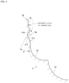
- the flange face 3k, the recess portion 3m, the seal land portion 3d, and the inner raceway groove 3c are subjected to turning by a turning tool, and the seal land portion 3d and the inner raceway groove 3c are further subjected to grinding by a grinding wheel after the turning.
- the flange face 3k is processed from the outer diameter side toward the inner diameter side, then the recess portion 3m is processed, and the seal land portion 3d and the inner raceway groove 3c are processed in order.
- grinding is simultaneously performed on the seal land portion 3d and the inner raceway groove 3c using a grinding wheel.
- the flange face 3k and the recess portion 3m have turning faces
- the seal land portion 3d and the inner raceway groove 3c have grinding faces.
- the recess portion 3m of the hub ring 3 can be subjected to post-processing such as shot blasting after turning.
- the recess portion 3m has a blasted face.
- the recess portion 3m is formed in an annular groove shape extending along the circumferential direction, and includes an outer diameter side edge portion 311, which serves as a boundary portion between the flange face 3k and the recess portion 3m, an inner diameter side edge portion 312, which serves as a boundary portion between the recess portion 3m and the seal land portion 3d, and a bottom portion 313, which is radially positioned between the outer diameter side edge portion 311 and the inner diameter side edge portion 312 and has the largest axial depth of the recess portion 3m.
- the inner diameter side edge portion 312 of the recess portion 3m is positioned on the outer diameter side relative to the contact portion 121 with respect to the seal land portion 3d of the second contact lip 12d positioned on the outermost diameter side among the contact lips included in the seal member 12.
- the inner diameter side edge portion 312 of the recess portion 3m is positioned on the outer diameter side by 1 mm or more relative to the contact portion 121 of the second contact lip 12d. That is, it is preferable that in the radial direction, a separation distance L1 between the inner diameter side edge portion 312 and the contact portion 121 is 1 mm or more.
- the inner diameter side edge portion 312 of the recess portion 3m is positioned on the outer diameter side relative to the contact portion 121 of the second contact lip 12d, when the hub ring 3 is rotating, for example, in a case where the radial position with respect to the hub ring 3 of the outer side opening portion 2b positioned at the axial one end portion of the outer ring 2 is displaced relatively to the outer diameter side, the contact portion 121 of the second contact lip 12d can be suppressed from falling off into the recess portion 3m to deteriorate the sealing performance.
- the inner diameter side edge portion 312 of the recess portion 3m is positioned on the outer diameter side relative to the contact portion 121 of the second contact lip 12d by 1 mm or more, even when the amount of radial positional displacement of the outer side opening portion 2b with respect to the hub ring 3 is large, it is possible to suppress the contact portion 121 from falling off into the recess portion 3m and the sealing performance from deteriorating.
- the inner diameter side edge portion 312 of the recess portion 3m is positioned on the outer diameter side relative to the contact portion with respect to the seal land portion 3d of the first contact lip 12c positioned on the inner diameter side of the second contact lip 12d, and even when the radial position with respect to the hub ring 3 of the outer side opening portion 2b of the outer ring 2 is relatively displaced to the outer diameter side, it is possible to suppress the contact portion with respect to the seal land portion 3d of the first contact lip 12c from falling off into the recess portion 3m and the sealing performance from deteriorating.
- the recess portion 3m includes a tapered face 314 radially extending from the outer diameter side edge portion 311 toward the bottom portion 313 side and inclined to the outer side from the outer diameter side edge portion 311 toward the bottom portion 313.
- the tapered face 314 is a tapered face in which an inclination angle ⁇ to the outer side with respect to the radial direction is an acute angle.
- the inclination angle ⁇ is set to be equal to or less than 26.5°.
- the turning tool moves along the movement locus illustrated in FIG. 4 .
- the recess portion 3m includes the tapered face 314, the turning tool can smoothly enter the recess portion 3m along the tapered face 314 from the flange face 3k, and the turning tool easily enters the recess portion 3m.
- the turning work of the hub ring 3 can be simplified.
- the inclination angle ⁇ to the outer side with respect to the radial direction of the tapered face 314 is a small angle of equal to or less than 26.5°, it is easy for the turning tool to enter the recess portion 3m from the flange face 3k, and the turning work of the hub ring 3 can be further simplified.
- the inner diameter side edge portion 312 of the recess portion 3m protrudes by a dimension D to the inner side on the outer side seal member 10 side relative to the outer diameter side edge portion 311 in the axial direction.
- the grinding wheel 15 does not come into contact with the outer diameter side edge portion 311 of the recess portion 3m when grinding the seal land portion 3d and the inner raceway groove grinding portion 15b, and the processability of grinding is not impaired. Since the outer diameter side edge portion 311 of the recess portion 3m is not ground by the grinding wheel 15, it is possible to suppress deterioration of the life of the grinding wheel 15 and the processing accuracy of the grinding.
- the hub ring 3 includes a heat treatment portion 31 quenched within a range where at least the inner raceway groove 3c, the seal land portion 3d, and the recess portion 3m are formed.
- the part where the inner raceway groove 3c and the seal land portion 3d are formed is entirely quenched, and the part where the recess portion 3m is formed is quenched in a partial range.
- the part where the recess portion 3m is formed can also be entirely quenched. Quenching may be applied to a range beyond the part where the inner raceway groove 3c, the seal land portion 3d, and the recess portion 3m are formed.
- the surface hardness and strength of the hub ring 3 are improved. Quenching in the heat treatment portion 31 can be performed by induction quenching, carburization quenching, or the like.
- the heat treatment portion 31 includes an outer peripheral edge 31a serving as a boundary with a non-heat treatment portion on the outer face of the hub ring 3, and the outer peripheral edge 31a on the outer diameter side in the heat treatment portion 31 is positioned on the outer diameter side relative to the bottom portion 313 of the recess portion 3m.
- the outer peripheral edge 31a of the heat treatment portion 31 is preferably positioned on the outer diameter side by 1 mm or more relative to the bottom portion 313 of the recess portion 3m. That is, it is preferable that in the radial direction, a separation distance L2 between the bottom portion 313 of the recess portion 3m and the outer peripheral edge 31a positioned on the outer diameter side relative to the bottom portion 313 is 1 mm or more.
- the outer peripheral edge 31a of the heat treatment portion 31 is disposed on the outer diameter side relative to the bottom portion 313 of the recess portion 3m, and the outer peripheral edge 31a is set not to be positioned at the bottom portion 313. This suppresses application of excessive stress to the bottom portion 313 of the recess portion 3m and can prevent a crack from occurring in the hub ring 3 with the bottom portion 313 of the recess portion 3m as a starting point.
- the present invention is applicable to a bearing device for vehicle wheel.
Landscapes
- Engineering & Computer Science (AREA)
- General Engineering & Computer Science (AREA)
- Mechanical Engineering (AREA)
- Manufacturing & Machinery (AREA)
- Rolling Contact Bearings (AREA)
- Sealing With Elastic Sealing Lips (AREA)
- Sealing Devices (AREA)
- Sealing Of Bearings (AREA)
Applications Claiming Priority (2)
| Application Number | Priority Date | Filing Date | Title |
|---|---|---|---|
| JP2021098729A JP7602435B2 (ja) | 2021-06-14 | 2021-06-14 | 車輪用軸受装置 |
| PCT/JP2022/022946 WO2022264880A1 (ja) | 2021-06-14 | 2022-06-07 | 車輪用軸受装置 |
Publications (2)
| Publication Number | Publication Date |
|---|---|
| EP4357631A1 true EP4357631A1 (de) | 2024-04-24 |
| EP4357631A4 EP4357631A4 (de) | 2024-11-06 |
Family
ID=84527466
Family Applications (1)
| Application Number | Title | Priority Date | Filing Date |
|---|---|---|---|
| EP22824872.0A Pending EP4357631A4 (de) | 2021-06-14 | 2022-06-07 | Radlagervorrichtung |
Country Status (5)
| Country | Link |
|---|---|
| US (1) | US12523252B2 (de) |
| EP (1) | EP4357631A4 (de) |
| JP (1) | JP7602435B2 (de) |
| CN (1) | CN117441067A (de) |
| WO (1) | WO2022264880A1 (de) |
Families Citing this family (1)
| Publication number | Priority date | Publication date | Assignee | Title |
|---|---|---|---|---|
| FR3151531A1 (fr) | 2023-07-28 | 2025-01-31 | Ntn Europe | Moyeu de roue de véhicule comprenant un siège de joint d'étanchéite, ensemble de roulement de roue et procédé de fabrication associés |
Family Cites Families (9)
| Publication number | Priority date | Publication date | Assignee | Title |
|---|---|---|---|---|
| JP2010180896A (ja) | 2009-02-03 | 2010-08-19 | Ntn Corp | 車輪用軸受シールおよびこれを備えた車輪用軸受装置 |
| JP2011089558A (ja) * | 2009-10-21 | 2011-05-06 | Ntn Corp | 車輪用軸受装置 |
| DE102011003704B4 (de) * | 2011-02-07 | 2018-09-13 | Schaeffler Technologies AG & Co. KG | Labyrinthdichtung eines Radiallagers mit Radialflansch |
| JP2013061048A (ja) | 2011-09-15 | 2013-04-04 | Nsk Ltd | シール付車輪支持用軸受ユニット |
| JP2013072553A (ja) | 2011-09-29 | 2013-04-22 | Nsk Ltd | シール付車輪支持用転がり軸受ユニット |
| DE102013217299B4 (de) * | 2013-08-30 | 2018-09-13 | Schaeffler Technologies AG & Co. KG | Dichtungsanordnung mit einem Schleuderring für ein Wälzlager |
| JP6392531B2 (ja) * | 2014-03-25 | 2018-09-19 | Ntn株式会社 | 車輪用軸受装置 |
| BR112018073599A2 (pt) | 2016-05-18 | 2019-02-26 | Nok Corporation | estrutura de vedação com cavidade anular e dispositivo de vedação |
| FR3056655B1 (fr) * | 2016-09-26 | 2019-07-19 | Ntn-Snr Roulements | Palier a roulement equipe d’un dispositif d’etancheite |
-
2021
- 2021-06-14 JP JP2021098729A patent/JP7602435B2/ja active Active
-
2022
- 2022-06-07 US US18/569,371 patent/US12523252B2/en active Active
- 2022-06-07 WO PCT/JP2022/022946 patent/WO2022264880A1/ja not_active Ceased
- 2022-06-07 EP EP22824872.0A patent/EP4357631A4/de active Pending
- 2022-06-07 CN CN202280040620.0A patent/CN117441067A/zh active Pending
Also Published As
| Publication number | Publication date |
|---|---|
| JP7602435B2 (ja) | 2024-12-18 |
| WO2022264880A1 (ja) | 2022-12-22 |
| EP4357631A4 (de) | 2024-11-06 |
| US12523252B2 (en) | 2026-01-13 |
| JP2022190415A (ja) | 2022-12-26 |
| CN117441067A (zh) | 2024-01-23 |
| US20240270017A1 (en) | 2024-08-15 |
Similar Documents
| Publication | Publication Date | Title |
|---|---|---|
| JP5184875B2 (ja) | 車輪用軸受装置 | |
| US9982713B2 (en) | Bearing apparatus for wheels | |
| US7942585B2 (en) | Wheel bearing apparatus for a vehicle | |
| EP3012475A1 (de) | Nabenlagereinheit mit einer dichtungsvorrichtung | |
| US20050157965A1 (en) | Bearing with tapered rolling bodies provided with a sealing device | |
| JP2015183801A (ja) | 車輪用軸受装置 | |
| JP2017125531A (ja) | 車輪用軸受装置 | |
| EP4357631A1 (de) | Radlagervorrichtung | |
| EP1947355A1 (de) | Lagervorrichtung für rad | |
| JP6629545B2 (ja) | 車輪用軸受装置 | |
| JP6012803B2 (ja) | 車輪用軸受装置 | |
| JP2008045673A (ja) | 車輪用軸受装置 | |
| JP2012056528A (ja) | 車輪用軸受装置 | |
| CN107107660B (zh) | 车轮轴承设备 | |
| US11298976B2 (en) | Bearing device for vehicle wheel | |
| JP5790109B2 (ja) | 転がり軸受装置 | |
| JP2009024804A (ja) | 密封装置 | |
| JP4780707B2 (ja) | 車輪用軸受装置 | |
| JP5236097B2 (ja) | 車輪用軸受装置 | |
| US12169001B2 (en) | Sensor bearing unit with improved breaking torque and method of manufacturing thereof | |
| JP2024119417A (ja) | 車輪用軸受装置 | |
| JP5024850B2 (ja) | 車輪用軸受装置 | |
| KR20130104668A (ko) | 실링 캡 및 이를 이용한 휠 베어링 조립체 | |
| JP2007100715A (ja) | 車輪用軸受装置 | |
| US20250043827A1 (en) | Wheel hub unit |
Legal Events
| Date | Code | Title | Description |
|---|---|---|---|
| STAA | Information on the status of an ep patent application or granted ep patent |
Free format text: STATUS: THE INTERNATIONAL PUBLICATION HAS BEEN MADE |
|
| PUAI | Public reference made under article 153(3) epc to a published international application that has entered the european phase |
Free format text: ORIGINAL CODE: 0009012 |
|
| STAA | Information on the status of an ep patent application or granted ep patent |
Free format text: STATUS: REQUEST FOR EXAMINATION WAS MADE |
|
| 17P | Request for examination filed |
Effective date: 20240109 |
|
| AK | Designated contracting states |
Kind code of ref document: A1 Designated state(s): AL AT BE BG CH CY CZ DE DK EE ES FI FR GB GR HR HU IE IS IT LI LT LU LV MC MK MT NL NO PL PT RO RS SE SI SK SM TR |
|
| DAV | Request for validation of the european patent (deleted) | ||
| DAX | Request for extension of the european patent (deleted) | ||
| A4 | Supplementary search report drawn up and despatched |
Effective date: 20241009 |
|
| RIC1 | Information provided on ipc code assigned before grant |
Ipc: F16J 15/447 20060101ALI20241002BHEP Ipc: B60B 27/00 20060101ALI20241002BHEP Ipc: F16J 15/328 20160101ALI20241002BHEP Ipc: F16J 15/3232 20160101ALI20241002BHEP Ipc: F16C 33/80 20060101ALI20241002BHEP Ipc: F16C 19/18 20060101ALI20241002BHEP Ipc: B60B 35/02 20060101ALI20241002BHEP Ipc: F16C 33/78 20060101AFI20241002BHEP |
|
| STAA | Information on the status of an ep patent application or granted ep patent |
Free format text: STATUS: EXAMINATION IS IN PROGRESS |
|
| 17Q | First examination report despatched |
Effective date: 20250530 |
|
| GRAP | Despatch of communication of intention to grant a patent |
Free format text: ORIGINAL CODE: EPIDOSNIGR1 |
|
| STAA | Information on the status of an ep patent application or granted ep patent |
Free format text: STATUS: GRANT OF PATENT IS INTENDED |
|
| INTG | Intention to grant announced |
Effective date: 20251212 |