EP4356939A1 - Blood purification device - Google Patents
Blood purification device Download PDFInfo
- Publication number
- EP4356939A1 EP4356939A1 EP22824590.8A EP22824590A EP4356939A1 EP 4356939 A1 EP4356939 A1 EP 4356939A1 EP 22824590 A EP22824590 A EP 22824590A EP 4356939 A1 EP4356939 A1 EP 4356939A1
- Authority
- EP
- European Patent Office
- Prior art keywords
- blood
- circuit
- pressure
- side circuit
- closed
- Prior art date
- Legal status (The legal status is an assumption and is not a legal conclusion. Google has not performed a legal analysis and makes no representation as to the accuracy of the status listed.)
- Pending
Links
Images






Classifications
-
- A—HUMAN NECESSITIES
- A61—MEDICAL OR VETERINARY SCIENCE; HYGIENE
- A61M—DEVICES FOR INTRODUCING MEDIA INTO, OR ONTO, THE BODY; DEVICES FOR TRANSDUCING BODY MEDIA OR FOR TAKING MEDIA FROM THE BODY; DEVICES FOR PRODUCING OR ENDING SLEEP OR STUPOR
- A61M1/00—Suction or pumping devices for medical purposes; Devices for carrying-off, for treatment of, or for carrying-over, body-liquids; Drainage systems
- A61M1/36—Other treatment of blood in a by-pass of the natural circulatory system, e.g. temperature adaptation, irradiation ; Extra-corporeal blood circuits
- A61M1/3621—Extra-corporeal blood circuits
- A61M1/3643—Priming, rinsing before or after use
-
- A—HUMAN NECESSITIES
- A61—MEDICAL OR VETERINARY SCIENCE; HYGIENE
- A61M—DEVICES FOR INTRODUCING MEDIA INTO, OR ONTO, THE BODY; DEVICES FOR TRANSDUCING BODY MEDIA OR FOR TAKING MEDIA FROM THE BODY; DEVICES FOR PRODUCING OR ENDING SLEEP OR STUPOR
- A61M1/00—Suction or pumping devices for medical purposes; Devices for carrying-off, for treatment of, or for carrying-over, body-liquids; Drainage systems
- A61M1/14—Dialysis systems; Artificial kidneys; Blood oxygenators ; Reciprocating systems for treatment of body fluids, e.g. single needle systems for hemofiltration or pheresis
- A61M1/30—Single needle dialysis ; Reciprocating systems, alternately withdrawing blood from and returning it to the patient, e.g. single-lumen-needle dialysis or single needle systems for hemofiltration or pheresis
-
- A—HUMAN NECESSITIES
- A61—MEDICAL OR VETERINARY SCIENCE; HYGIENE
- A61M—DEVICES FOR INTRODUCING MEDIA INTO, OR ONTO, THE BODY; DEVICES FOR TRANSDUCING BODY MEDIA OR FOR TAKING MEDIA FROM THE BODY; DEVICES FOR PRODUCING OR ENDING SLEEP OR STUPOR
- A61M1/00—Suction or pumping devices for medical purposes; Devices for carrying-off, for treatment of, or for carrying-over, body-liquids; Drainage systems
- A61M1/36—Other treatment of blood in a by-pass of the natural circulatory system, e.g. temperature adaptation, irradiation ; Extra-corporeal blood circuits
- A61M1/3621—Extra-corporeal blood circuits
- A61M1/3627—Degassing devices; Buffer reservoirs; Drip chambers; Blood filters
-
- A—HUMAN NECESSITIES
- A61—MEDICAL OR VETERINARY SCIENCE; HYGIENE
- A61M—DEVICES FOR INTRODUCING MEDIA INTO, OR ONTO, THE BODY; DEVICES FOR TRANSDUCING BODY MEDIA OR FOR TAKING MEDIA FROM THE BODY; DEVICES FOR PRODUCING OR ENDING SLEEP OR STUPOR
- A61M1/00—Suction or pumping devices for medical purposes; Devices for carrying-off, for treatment of, or for carrying-over, body-liquids; Drainage systems
- A61M1/36—Other treatment of blood in a by-pass of the natural circulatory system, e.g. temperature adaptation, irradiation ; Extra-corporeal blood circuits
- A61M1/3621—Extra-corporeal blood circuits
- A61M1/3643—Priming, rinsing before or after use
- A61M1/3644—Mode of operation
- A61M1/3646—Expelling the residual body fluid after use, e.g. back to the body
-
- A—HUMAN NECESSITIES
- A61—MEDICAL OR VETERINARY SCIENCE; HYGIENE
- A61M—DEVICES FOR INTRODUCING MEDIA INTO, OR ONTO, THE BODY; DEVICES FOR TRANSDUCING BODY MEDIA OR FOR TAKING MEDIA FROM THE BODY; DEVICES FOR PRODUCING OR ENDING SLEEP OR STUPOR
- A61M1/00—Suction or pumping devices for medical purposes; Devices for carrying-off, for treatment of, or for carrying-over, body-liquids; Drainage systems
- A61M1/36—Other treatment of blood in a by-pass of the natural circulatory system, e.g. temperature adaptation, irradiation ; Extra-corporeal blood circuits
- A61M1/3621—Extra-corporeal blood circuits
- A61M1/3643—Priming, rinsing before or after use
- A61M1/3644—Mode of operation
- A61M1/3649—Mode of operation using dialysate as priming or rinsing liquid
-
- A—HUMAN NECESSITIES
- A61—MEDICAL OR VETERINARY SCIENCE; HYGIENE
- A61M—DEVICES FOR INTRODUCING MEDIA INTO, OR ONTO, THE BODY; DEVICES FOR TRANSDUCING BODY MEDIA OR FOR TAKING MEDIA FROM THE BODY; DEVICES FOR PRODUCING OR ENDING SLEEP OR STUPOR
- A61M1/00—Suction or pumping devices for medical purposes; Devices for carrying-off, for treatment of, or for carrying-over, body-liquids; Drainage systems
- A61M1/36—Other treatment of blood in a by-pass of the natural circulatory system, e.g. temperature adaptation, irradiation ; Extra-corporeal blood circuits
- A61M1/3621—Extra-corporeal blood circuits
- A61M1/3643—Priming, rinsing before or after use
- A61M1/3644—Mode of operation
- A61M1/365—Mode of operation through membranes, e.g. by inverted trans-membrane pressure [TMP]
-
- A—HUMAN NECESSITIES
- A61—MEDICAL OR VETERINARY SCIENCE; HYGIENE
- A61M—DEVICES FOR INTRODUCING MEDIA INTO, OR ONTO, THE BODY; DEVICES FOR TRANSDUCING BODY MEDIA OR FOR TAKING MEDIA FROM THE BODY; DEVICES FOR PRODUCING OR ENDING SLEEP OR STUPOR
- A61M1/00—Suction or pumping devices for medical purposes; Devices for carrying-off, for treatment of, or for carrying-over, body-liquids; Drainage systems
- A61M1/36—Other treatment of blood in a by-pass of the natural circulatory system, e.g. temperature adaptation, irradiation ; Extra-corporeal blood circuits
- A61M1/3621—Extra-corporeal blood circuits
- A61M1/3643—Priming, rinsing before or after use
- A61M1/3644—Mode of operation
- A61M1/3652—Mode of operation using gas, e.g. air
-
- A—HUMAN NECESSITIES
- A61—MEDICAL OR VETERINARY SCIENCE; HYGIENE
- A61M—DEVICES FOR INTRODUCING MEDIA INTO, OR ONTO, THE BODY; DEVICES FOR TRANSDUCING BODY MEDIA OR FOR TAKING MEDIA FROM THE BODY; DEVICES FOR PRODUCING OR ENDING SLEEP OR STUPOR
- A61M60/00—Blood pumps; Devices for mechanical circulatory actuation; Balloon pumps for circulatory assistance
- A61M60/10—Location thereof with respect to the patient's body
- A61M60/104—Extracorporeal pumps, i.e. the blood being pumped outside the patient's body
- A61M60/109—Extracorporeal pumps, i.e. the blood being pumped outside the patient's body incorporated within extracorporeal blood circuits or systems
-
- A—HUMAN NECESSITIES
- A61—MEDICAL OR VETERINARY SCIENCE; HYGIENE
- A61M—DEVICES FOR INTRODUCING MEDIA INTO, OR ONTO, THE BODY; DEVICES FOR TRANSDUCING BODY MEDIA OR FOR TAKING MEDIA FROM THE BODY; DEVICES FOR PRODUCING OR ENDING SLEEP OR STUPOR
- A61M60/00—Blood pumps; Devices for mechanical circulatory actuation; Balloon pumps for circulatory assistance
- A61M60/20—Type thereof
- A61M60/205—Non-positive displacement blood pumps
- A61M60/216—Non-positive displacement blood pumps including a rotating member acting on the blood, e.g. impeller
-
- A—HUMAN NECESSITIES
- A61—MEDICAL OR VETERINARY SCIENCE; HYGIENE
- A61M—DEVICES FOR INTRODUCING MEDIA INTO, OR ONTO, THE BODY; DEVICES FOR TRANSDUCING BODY MEDIA OR FOR TAKING MEDIA FROM THE BODY; DEVICES FOR PRODUCING OR ENDING SLEEP OR STUPOR
- A61M60/00—Blood pumps; Devices for mechanical circulatory actuation; Balloon pumps for circulatory assistance
- A61M60/40—Details relating to driving
- A61M60/403—Details relating to driving for non-positive displacement blood pumps
- A61M60/408—Details relating to driving for non-positive displacement blood pumps the force acting on the blood contacting member being mechanical, e.g. transmitted by a shaft or cable
-
- A—HUMAN NECESSITIES
- A61—MEDICAL OR VETERINARY SCIENCE; HYGIENE
- A61M—DEVICES FOR INTRODUCING MEDIA INTO, OR ONTO, THE BODY; DEVICES FOR TRANSDUCING BODY MEDIA OR FOR TAKING MEDIA FROM THE BODY; DEVICES FOR PRODUCING OR ENDING SLEEP OR STUPOR
- A61M60/00—Blood pumps; Devices for mechanical circulatory actuation; Balloon pumps for circulatory assistance
- A61M60/50—Details relating to control
- A61M60/508—Electronic control means, e.g. for feedback regulation
-
- A—HUMAN NECESSITIES
- A61—MEDICAL OR VETERINARY SCIENCE; HYGIENE
- A61M—DEVICES FOR INTRODUCING MEDIA INTO, OR ONTO, THE BODY; DEVICES FOR TRANSDUCING BODY MEDIA OR FOR TAKING MEDIA FROM THE BODY; DEVICES FOR PRODUCING OR ENDING SLEEP OR STUPOR
- A61M2205/00—General characteristics of the apparatus
- A61M2205/07—General characteristics of the apparatus having air pumping means
-
- A—HUMAN NECESSITIES
- A61—MEDICAL OR VETERINARY SCIENCE; HYGIENE
- A61M—DEVICES FOR INTRODUCING MEDIA INTO, OR ONTO, THE BODY; DEVICES FOR TRANSDUCING BODY MEDIA OR FOR TAKING MEDIA FROM THE BODY; DEVICES FOR PRODUCING OR ENDING SLEEP OR STUPOR
- A61M2205/00—General characteristics of the apparatus
- A61M2205/33—Controlling, regulating or measuring
- A61M2205/3331—Pressure; Flow
Definitions
- the present invention relates to a blood purification apparatus that self-evaluates the connection state of a blood circuit in draining liquid in the blood circuit.
- a blood purification apparatus can be used in treating a patient.
- a blood purification apparatus has a blood circuit for removing blood from the body of a patient and returning blood into the body again.
- the blood circuit is mainly formed of a blood removal circuit (also called an arterial side circuit) and a blood return circuit (also called a venous side circuit) that may be connected to a dialyzer.
- the dialyzer is known as a blood purifier.
- Patent Literature 1 discloses a method for draining liquid in a blood circuit hygienically and safely for a patient by making the blood circuit a closed loop.
- Patent Literature 1 does not address a method for checking the connection state of the blood circuit before starting drainage of liquid in the blood circuit. In a case where drainage is done without a proper closed circuit being formed, leakage of liquid from the blood circuit occurs, and in a case where the patient is still connected, unnecessary blood removal may be performed. In this way, problematically, drainage may be performed improperly.
- Patent Literature 2 discloses a method for stopping a blood pump and restricting the operation to a low-speed operation in a case where there is a possibility of a needle being connected to a patient in a process before drainage of liquid in the blood circuit is performed.
- Patent Literature 2 does not address determination of the AV coupled state.
- the present invention aims to determine if the blood circuit is in the AV coupled state in performing drainage of liquid in the blood circuit.
- a blood purification apparatus includes: a blood circuit having a blood removal side circuit into which blood removed from a patient flows and a blood return side circuit from which blood is returned to the patient and being able to form a closed circuit by having a first end portion of the blood removal side circuit and a first end portion of the blood return side circuit connected to each other via a blood purifier and by having a second end portion of the blood removal side circuit and a second end portion of the blood return side circuit connected to each other directly or indirectly; a blood pump provided at the blood circuit; a flow channel switch unit capable of switching between an open state in which fluid is able to flow through the first end portions of the blood removal side circuit and the blood return side circuit and a closed state in which the fluid is unable to flow through the first end portions of the blood removal side circuit and the blood return side circuit; a pressure detection unit that detects pressure inside the blood circuit; and a control unit that executes a drainage process of draining liquid remaining in the blood circuit to a predetermined drainage destination with the blood circuit
- the control unit further executes a determination process in which the control unit generates a difference in pressure between the blood removal side circuit and the blood return side circuit by rotating the blood pump with the flow channel switch unit switched to the closed state, and then determines whether the blood circuit is the closed circuit by switching the flow channel switch unit to the open state and monitoring the difference in pressure based on a result of detection by the pressure detection unit. In a case where it is determined in the determination process that the blood circuit is the closed circuit, the control unit executes the drainage process after the determination.
- the blood purification apparatus can self-evaluate that the blood circuit is in an AV coupled state in performing drainage of liquid in the AV-coupling-type blood circuit.
- a blood purification apparatus can be a device used for dialysis treatment, the gist of the present invention can also be applied to devices other than ones for dialysis treatment.
- a blood purification apparatus includes a piping unit for allowing a dialysate to flow into a dialyzer and an extracorporeal circulation unit for allowing the blood of a patient to flow into the dialyzer.
- the gist of the present invention is described with reference to the configuration of the extracorporeal circulation unit of the blood purification apparatus.
- an artery may be referred to as "A” based on the initial letter of the English word
- a vein may be referred to as "V” based on the initial letter of the English word.
- A an artery
- V a vein
- drainage process means a process of draining liquid in the blood circuit.
- Fig. 1 is a piping diagram showing the configuration of a blood purification apparatus 100 according to a first embodiment.
- Fig. 1 shows that a blood removal circuit can be connected to a blood vessel of a patient at a patient connection portion 11 of the blood removal circuit and that a blood return circuit can be connected to a blood vessel of the patient at a patient connection portion 12 of the blood return circuit.
- the patient connection portion 11 of the blood removal circuit and the patient connection portion 12 of the blood return circuit are pulled out of the body of the patient and are coupled to each other so that a blood circuit 16 may be a closed loop.
- the patient connection portion 11 and the patient connection portion 12 may be coupled to each other via a given coupler. This is called an AV coupled state 13 herein.
- the blood purification apparatus 100 includes an ACLP, an A chamber 14, a PCLP, an A pressure sensor 15, the blood circuit 16, a blood pump (BP1), a DI chamber 17, a DI pressure sensor 18, a blood purifier 19, a V chamber 20, a V pressure sensor 21, a VCLP, a solenoid valve 22, a drainer 23, and a controller 24.
- the controller 24 controls the operation of the blood purification apparatus 100 described herein. Note that the controller 24 is configured by appropriately combining a CPU, a ROM, a RAM, and various interfaces.
- the ACLP is a clamp attached to the blood removal circuit
- the VCLP is a clamp attached to the blood return circuit
- the PCLP is a clamp attached to a line (a priming line) for introducing a dialysate, a physiological saline solution, or the like into the blood circuit 16 at the time of, e.g., priming of the blood circuit 16.
- the clamp may be a solenoid valve that closes or opens the blood circuit 16 by opening and closing operations.
- the A chamber 14 traps air in the blood removal circuit.
- the DI chamber 17 traps air in the blood flowing to the blood purifier 19.
- the V chamber 20 traps air in the blood return circuit.
- the A pressure sensor 15 is a pressure sensor for measuring the pressure inside the blood circuit 16 at the A chamber 14.
- the DI pressure sensor 18 is a pressure sensor for measuring the pressure inside the blood circuit 16 at the DI chamber 17.
- the V pressure sensor 21 is a pressure sensor for measuring the pressure inside the blood circuit 16 at the V chamber 20.
- the BP1 can send the blood, physiological saline solution, and air in the blood circuit 16 in a predetermined direction.
- the forward rotation means clockwise rotation
- the backward rotation means counterclockwise rotation.
- the blood purifier 19 may be called a dialyzer.
- the blood purifier 19 has a blood purification membrane thereinside and also has a blood introduction inlet for introducing blood, a blood introduction outlet for letting out the introduced blood, a dialysate introduction inlet for introducing a dialysate, and a dialysate drainage outlet for draining the introduced dialysate.
- the blood purifier 19 purifies the blood introduced from the blood introduction inlet by bringing it into contact with the dialysate via the blood purification membrane.
- the drainer 23 is a degassing pump or water removal pump that drains waste and moisture in the blood sent via a drainage circuit from the blood purifier 19.
- the drainage circuit is a circuit connecting between the blood purifier 19 and the drainer 23 and shown with a broken line in Fig. 1 .
- the solenoid valve 22 is attached between the blood purifier 19 and the drainer 23 and closes or opens the drainage circuit by opening and closing operations.
- the patient connection portion 11 of the blood removal circuit and the patient connection portion 12 of the blood return circuit need to be coupled either indirectly via a given coupler or directly without any coupler to make the blood circuit 16 a closed loop.
- the blood purification apparatus 100 determines if the V pressure sensor 21 and the blood circuit 16 are connected. Specifically, the blood purification apparatus 100 closes the ACLP, the VCLP, and the solenoid valve 22, opens the PCLP to introduce air, physiological saline solution, or dialysate from the priming line, and rotates the BP1 forwards. This operation causes the V side to have increased pressure.
- Fig. 3 is a diagram showing this state (a first state). Because the ACLP, the VCLP, and the solenoid valve 22 are closed, they are shown distinguishably from the PCLP. Because the BP1 is rotating forwards, the introduced air, physiological saline solution, or dialysate travels in the blood circuit 16 along the arrows indicating the first direction 30. In Fig. 3 , the direction in which the air, physiological saline solution, or dialysate travels is shown with a plurality of arrows. As a result of this operation, the V side is brought to positive pressure.
- Reasons for closing the ACLP and the VCLP are to eliminate the risk of bubbles entering the patient even in a case where the blood return circuit is connected to the patient and also to prevent blood removal in a case where the blood removal circuit is connected to the patient.
- the blood purification apparatus 100 determines that the V pressure sensor 21 and the blood circuit 16 are connected, and the processing proceeds to S203.
- a predetermined criterion can be used as a criterion for determining whether the V side is under increased pressure. If it is determined that the V side is not under increased pressure, it is determined that the V pressure sensor 21 and the blood circuit 16 are not connected, and the processing proceeds to S209.
- the blood purification apparatus 100 determines if the A side is not connected to the patient. The reason for performing this determination is because if the blood removal circuit is connected to the patient, then blood will be removed from the patient. Specifically, the blood purification apparatus 100 closes the PCLP, opens the ACLP and the solenoid valve 22, and then rotates the BP1 forwards. Unlike the processing in S201, because the PCLP is closed, air, physiological saline solution, or dialysate is not introduced into the blood circuit 16, and the A side is brought to negative pressure.
- Fig. 4 is a diagram showing this state (a second state). Fig. 4 shows that the BP1 is rotating forwards and the A side is under negative pressure.
- the blood purification apparatus 100 can reduce the pressure of the downstream side (the V side) by opening the solenoid valve 22.
- the blood purification apparatus 100 determines if the A side is not connected to the patient. Specifically, the blood purification apparatus 100 closes the solenoid valve 22, stops the rotation of the BP1, and measures a change in the A pressure afterwards using the A pressure sensor 15.
- the BP1 is a roller pump, and once the BP1 is stopped, the BP1 part is closed, making the part from the VCLP to the ACLP to the BP1 a closed circuit and keeping the A side under negative pressure. Any given condition can be set as the condition for the A side being under negative pressure, and the condition may be such that a change in the A pressure in a predetermined period of time after the BP1 is stopped falls within a predetermined range.
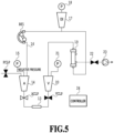
- Fig. 5 is a diagram showing this state (a third state). While the ACLP is open, the PCLP and the VCLP are still closed, and the BP1 is stopped; thus, the A side pressure remains under negative pressure.
- the blood purification apparatus 100 determines if the A side and the V side of the blood circuit 16 are coupled and the AV coupled state 13 is established. Specifically, the blood purification apparatus 100 brings the ACLP and the VCLP into an open state by opening the VCLP, measures the A pressure and the V pressure using the A pressure sensor 15 and the V pressure sensor 21, respectively, and compares the pressure difference between them. The PCLP and the solenoid valve 22 are still closed.
- the condition for establishment of the AV coupled state 13 is, for example, the difference between the A pressure and the V pressure becoming so small as to fall within a predetermined range.
- the reason for bringing the ACLP and the VCLP into an open state is to balance (equalize) the pressures at the A side and the V side.
- Fig. 6 is a diagram showing this state (a fourth state). Because the BP1 is stopped, the residual liquid moves so as to balance the pressures at the A side and the V side. In this state, the blood purification apparatus 100 determines whether the condition for establishment of the AV coupled state 13 is satisfied by measuring the A pressure and the V pressure using the A pressure sensor 15 and the V pressure sensor 21, respectively, and comparing the pressure difference between them.
- the processing proceeds to S208, it means that before performing drainage of liquid in the AV-coupling-type blood circuit, the blood purification apparatus 100 has successfully self-evaluated that the blood circuit 16 is in the AV coupled state 13 (a closed loop state) as a result of the above-described processing.
- Fig. 7 is a diagram illustrating the operation for draining liquid from the blood circuit 16 in the AV coupled state 13.
- the blood purification apparatus 100 introduces air from an upper portion of the V chamber 20, an upper portion of the A chamber 14, or a given opening portion of the blood circuit 16 (such as, e.g., the PCLP or an upper portion of the DI chamber 17) and rotates the BP1 forwards. Once the BP1 rotates forwards, liquid remaining in the blood circuit 16 flows in the first direction 30 and is drained from the drainer 23 via the blood purifier 19, as shown in Fig. 7 .
- the blood purification apparatus 100 may control the amount of rotation of the BP 1 in any given way.
- the blood purification apparatus 100 can start rotating the BP1 while restricting the rotation amount to a first rotation amount and then after a predetermined period of time passes, increase the rotation amount to a second rotation amount.
- a reason for controlling the rotational amount of the BP1 this way is to reduce the amount of blood removed from the body of the patient, should the blood removal circuit be connected to the patient.
- the blood purification apparatus 100 can also be configured to start the drainage operation, and then in a case where it is determined that the blood circuit 16 is a closed loop, continue the drainage operation, or in a case where the blood circuit 16 is not a closed loop, abort the drainage operation at that point.
- Fig. 8 is a diagram showing lists of the A pressures and the V pressures in the first to fourth states.
- V pressure increases in S201 and then reduces in S206, while the A pressure reduces in S203 and increases in S206.
- connection state is abnormal.
- the A pressure increases in S204, causing an error.
- the A pressure does not change, causing an error.
- the V pressure remains increased and the A pressure remains reduced.
- the puncture needle of the patient connection portion 11 of the blood removal circuit and the puncture needle of the patient connection portion 12 of the blood return circuit are both connected to the patient.
- an SNDP single-needle double-pump
- single-needle dialysis is a method for carrying out dialysis by having a route only at a single location on the patient and repeating blood removal and blood return alternately, and uses a special bifurcated needle or a bifurcated tube. Because liquid in the blood circuit may be drained and disposed of after a treatment in the single-needle approach as well, the self-evaluation method according to the present invention in performing drainage of liquid in the AV-coupling-type blood circuit can be applied.
- the configuration of the second embodiment is such that a second blood pump (BP2), an SN chamber 25, and an SN pressure sensor 26 are added to the configuration of the first embodiment.
- the BP2 is a pump for increasing or reducing the pressure at the V side.
- the SN chamber 25 is formed of the same member as the A chamber 14, the DI chamber 17, and the V chamber 20 and plays the role as a buffer that accumulates pressure during a single-need treatment.
- the SN pressure sensor 26 is a pressure sensor for measuring the pressure inside the blood circuit 16 at the SN chamber 25. Referring to the configuration in Fig.
- the BP1 is rotated and the BP2 is stopped to accumulate pressure in the SN chamber 25, and at the time of blood return, the BP1 is stopped and the BP2 is rotated to return, to the patient, blood corresponding to the pressure accumulated in the SN chamber 25.
- Fig. 9 is a diagram illustrating an operation flow of self-evaluation according to the second embodiment carried out in starting drainage of liquid in the AV-coupling-type blood circuit.
- the operation flow in Fig. 9 is similar to the operation flow described with Fig. 2 .
- the self-evaluation is performed to confirm that the blood circuit 16 is in the AV coupled state 13, i.e., in a closed-loop state.
- the blood purification apparatus 100 determines if the V pressure sensor 21 and the blood circuit 16 are connected. Specifically, the blood purification apparatus 100 closes the ACLP, the VCLP, and the solenoid valve 22 and opens the PCLP to introduce air, physiological saline solution, or dialysate from the priming line, and rotates the BP1 and the BP2 forwards. This operation causes the V side to be increased in pressure.
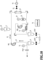
- Fig. 10 is a diagram showing this state (a fifth state). Because the ACLP, the VCLP, and the solenoid valve 22 are closed, they are shown distinguishably from the PCLP. Because the BP1 and the BP2 are rotating forwards, the introduced air, physiological saline solution, or dialysate travels in the blood circuit 16 along the arrows indicating the first direction 30. In Fig. 10 , the direction in which the air, physiological saline solution, or dialysate travels is shown with a plurality of arrows. As a result of this operation, the V side is brought to positive pressure.
- Reasons for closing the ACLP and the VCLP is to eliminate the risk of bubbles entering the patient even if the blood return circuit is connected to the patient and also to prevent blood removal in a case where the blood removal circuit is connected to the patient.
- the blood purification apparatus 100 determines that the V pressure sensor 21 and the blood circuit 16 are connected, and the processing proceeds to S903.
- a predetermined criterion can be used as a criterion for determining whether the V side is under increased pressure.
- it is determined that the V side is not under increased pressure it is determined that the V pressure sensor 21 and the blood circuit 16 are not connected, and the processing proceeds to S909.
- the blood purification apparatus 100 determines if the A side is not connected to the patient. The reason for performing this determination is because if the blood removal circuit is connected to the patient, then blood will be removed from the patient. Specifically, the blood purification apparatus 100 closes the PCLP and opens the ACLP and the solenoid valve 22, and then rotates the BP1 forwards and the BP2 backwards. Unlike the processing in S901, because the PCLP is closed, air, physiological saline solution, or dialysate is not introduced into the blood circuit 16, and the A side is brought to negative pressure.
- Fig. 11 is a diagram showing this state (a sixth state). Because the BP1 is rotating forwards, the A side is under negative pressure. Also, because the BP2 is rotating backwards, the V side is reduced in pressure.
- the forward rotation of the BP1 and the backward rotation of the BP2 cause the liquid such as blood remaining in the blood circuit 16 to be drained from the drainer 23 via the blood purifier 19 and the solenoid valve 22, and the V side is reduced in pressure.
- the blood purification apparatus 100 determines if the A side is not connected to the patient. Specifically, the blood purification apparatus 100 closes the solenoid valve 22, stops the rotation of the BP1 and the BP2, and measures a change in the A pressure afterwards using the A pressure sensor 15.
- the BP1 is a roller pump, and once the BP1 is stopped, the BP1 part is closed, making the part from the VCLP to the ACLP to the BP1 a closed circuit and keeping the A side under negative pressure. Any given condition can be set as the condition for the A side being under negative pressure, and the condition may be such that a change in the A pressure in a predetermined period of time after the BP1 and the BP2 are stopped falls within a predetermined range.
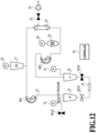
- Fig. 12 is a diagram showing this state (a seventh state). While the ACLP is open, the PCLP and the VCLP are still closed, and the BP1 is stopped; thus, the A side pressure is still under negative pressure.
- the blood purification apparatus 100 determines if the A side and the V side of the blood circuit 16 are coupled and the AV coupled state 13 is established. Specifically, the blood purification apparatus 100 brings the ACLP and the VCLP into an open state by opening the VCLP, measures the A pressure and the V pressure using the A pressure sensor 15 and the V pressure sensor 21, respectively, and compares the pressure difference between them. The PCLP and the solenoid valve 22 are still closed.
- the condition for establishment of the AV coupled state 13 is, for example, the difference between the A pressure and the V pressure becoming so small as to fall within a predetermined range.
- the reason for bringing the ACLP and the VCLP into an open state is to balance (equalize) the pressures at the A side and the V side.
- Fig. 13 is a diagram showing this state (an eighth state). Because the BP1 and the BP2 are stopped, the residual liquid moves to balance the pressures at the A side and the V side. In this state, the blood purification apparatus 100 determines whether the condition for establishment of the AV coupled state 13 is satisfied by measuring the A pressure and the V pressure using the A pressure sensor 15 and the V pressure sensor 21, respectively, and comparing the pressure difference between them.
- the processing proceeds to S908, it means that before performing drainage of liquid in the AV-coupling-type blood circuit, the blood purification apparatus 100 has successfully self-evaluated that the blood circuit 16 is in the AV coupled state 13 (a closed loop state) as a result of the above-described processing.
- the blood purification apparatus 100 starts an operation for draining liquid in the AV-coupling-type blood circuit.
- the blood purification apparatus 100 introduces air from an upper portion of the V chamber 20, an upper portion of the A chamber 14, or a given opening portion of the blood circuit 16 (such as, e.g., the PCLP or an upper portion of the DI chamber 17) and rotates the BP1 forwards and the BP2 backwards. Once the BP1 rotates forwards, liquid remaining in the blood removal circuit flows in the first direction 30, liquid remaining in the blood return circuit flows in the second direction 40, and the liquid is drained from the drainer 23 via the blood purifier 19.
- the blood purification apparatus 100 may control the amount of rotation of the BP1 in any given way.
- the blood purification apparatus 100 can start rotating the BP1 while restricting the rotation amount to a first rotation amount and then after a predetermined period of time passes, increase the rotation amount to a second rotation amount.
- a reason for controlling the rotational amount of the BP1 this way is to reduce the amount of blood removed from the body of the patient, should the blood removal circuit be connected to the patient.
- the blood purification apparatus 100 can also be configured to start the drainage operation, and then in a case where it is determined that the blood circuit 16 is a closed loop, continue the drainage operation, or in a case where the blood circuit 16 is not a closed loop, abort the drainage operation at that point.
- the blood purification apparatus 100 aborts the operation for draining liquid in the blood circuit 16.
- a third embodiment is a configuration having a third blood pump (BP3) installed between the blood purifier 19 and the V chamber 20 in the configuration of the first embodiment.
- the installation position of the BP3 may be the same as that in the second embodiment.
- the V pressure increases as the BP3 rotates forwards, and the V pressure reduces as the BP3 rotates backwards.
- the blood purification apparatus 100 closes the ACLP, the VCLP, and the solenoid valve 22 and opens the PCLP to introduce air from the priming line, and rotates the BP1 forwards and the BP3 forwards.
- This operation causes the V side to be increased in pressure.
- the V side is brought to positive pressure relatively fast compared to the first embodiment because the BP1 and the BP3 are rotating forwards.
- the blood purification apparatus 100 closes the PCLP and opens the ACLP and the solenoid valve 22, and then rotates the BP1 forwards and the BP3 backwards. Unlike the processing in S201, because the PCLP is closed, air is not introduced into the blood circuit 16, and the A side is brought to negative pressure. The blood purification apparatus 100 can reduce the pressure at the V side by rotating the BP3 backwards and opening the solenoid valve 22.
- the third embodiment can perform self-evaluation more efficiently and faster than the first embodiment.
- a first mode of the present invention is a blood purification apparatus including: a blood circuit having a blood removal side circuit into which blood removed from a patient flows and a blood return side circuit from which blood is returned to the patient and being able to form a closed circuit by having a first end portion of the blood removal side circuit and a first end portion of the blood return side circuit connected to each other via a blood purifier and by having a second end portion of the blood removal side circuit and a second end portion of the blood return side circuit connected to each other directly or indirectly; a blood pump provided at the blood circuit; a flow channel switch unit capable of switching between an open state in which fluid is able to flow through the first end portions of the blood removal side circuit and the blood return side circuit and a closed state in which the fluid is unable to flow through the first end portions of the blood removal side circuit and the blood return side circuit; a pressure detection unit that detects pressure inside the blood circuit; and a control unit that executes a drainage process of draining liquid remaining in the blood circuit to a predetermined drainage destination with the
- the control unit further executes a determination process in which the control unit generates a difference in pressure between the blood removal side circuit and the blood return side circuit by rotating the blood pump with the flow channel switch unit switched to the closed state, and then determines whether the blood circuit is the closed circuit by switching the flow channel switch unit to the open state and monitoring the difference in pressure based on a result of detection by the pressure detection unit, and in a case where it is determined in the determination process that the blood circuit is the closed circuit, the control unit executes the drainage process after the determination.
- the blood purification apparatus can self-evaluate that the blood circuit is in an AV coupled state.
- the blood pump is a first blood pump provided at the blood removal side circuit
- the blood purification apparatus further comprises a second blood pump provided at the blood return side circuit.
- the control unit generates a difference in pressure between the blood removal side circuit and the blood return side circuit by switching the flow channel switch unit to the closed state and rotating the first blood pump and the second blood pump in a first direction and then determines whether the blood circuit is the closed circuit by switching the flow channel switch unit to the open state and monitoring the difference in pressure based on a result of detection by the pressure detection unit.
- the difference in pressure is a difference in pressure with the blood removal side circuit being negative pressure and the blood return side circuit being positive pressure.
- the blood purification apparatus can monitor the pressure difference between the blood removal side circuit at negative pressure and the blood return side circuit at positive pressure.
- the control unit determines whether the blood circuit is the closed circuit based on a result of the monitoring of the difference in pressure, and the result of the monitoring of the difference in pressure indicates that the difference in pressure generated between the blood removal side circuit and the blood return side circuit has reduced.
- the blood purification apparatus further includes an introduction portion that introduces a first fluid into the blood circuit, the first fluid being for draining the liquid remaining in the blood circuit.
- the control unit With the flow channel switch unit being switched to the open state, the control unit introduces the first fluid from the introduction portion into the blood circuit and rotates the blood pump, thereby draining the liquid remaining in the blood circuit to the predetermined drainage destination.
- the blood purification apparatus can drain liquid remaining in the blood circuit to a predetermined drainage destination by introducing the first fluid into the blood circuit and rotating the blood pump.
- introduction material is air, physiological saline solution, or dialysate.
- a seventh mode of the present invention is a method executed by a blood purification apparatus including a blood circuit having a blood removal side circuit into which blood removed from a patient flows and a blood return side circuit from which blood is returned to the patient and being able to form a closed circuit by having a first end portion of the blood removal side circuit and a first end portion of the blood return side circuit connected to each other via a blood purifier and having a second end portion of the blood removal side circuit and a second end portion of the blood return side circuit connected to each other directly or indirectly; a blood pump provided at the blood circuit, a flow channel switch unit capable of switching between an open state in which fluid is able to flow through the first end portions of the blood removal side circuit and the blood return side circuit and a closed state in which the fluid is unable to flow through the first end portions of the blood removal side circuit and the blood return side circuit; a pressure detection unit that detects pressure inside the blood circuit, and a control unit that executes a drainage process of draining liquid remaining in the blood circuit to a predetermined drainage
- the method includes: generating, by the control unit, a difference in pressure between the blood removal side circuit and the blood return side circuit by rotating the blood pump with the flow channel switch unit switched to the closed state; determining, by the control unit, whether the blood circuit is the closed circuit by switching the flow channel switch unit to the open state and monitoring the difference in pressure based on a result of detection by the pressure detection unit; and in a case where it is determined in the determination process that the blood circuit is the closed circuit, executing, by the control unit, the drainage process after the determination.
- the blood purification apparatus can self-evaluate that the blood circuit is in an AV coupled state.
- the present invention may be implemented as modes such as, for example, a system, an apparatus, a method, a program, or a storage medium.
Landscapes
- Health & Medical Sciences (AREA)
- Heart & Thoracic Surgery (AREA)
- Engineering & Computer Science (AREA)
- Vascular Medicine (AREA)
- Life Sciences & Earth Sciences (AREA)
- Anesthesiology (AREA)
- Biomedical Technology (AREA)
- Hematology (AREA)
- Animal Behavior & Ethology (AREA)
- General Health & Medical Sciences (AREA)
- Public Health (AREA)
- Veterinary Medicine (AREA)
- Cardiology (AREA)
- Mechanical Engineering (AREA)
- Urology & Nephrology (AREA)
- Emergency Medicine (AREA)
- External Artificial Organs (AREA)
Abstract
Description
- The present invention relates to a blood purification apparatus that self-evaluates the connection state of a blood circuit in draining liquid in the blood circuit.
- A blood purification apparatus can be used in treating a patient. A blood purification apparatus has a blood circuit for removing blood from the body of a patient and returning blood into the body again. The blood circuit is mainly formed of a blood removal circuit (also called an arterial side circuit) and a blood return circuit (also called a venous side circuit) that may be connected to a dialyzer. The dialyzer is known as a blood purifier.
- After treatment of a patient, puncture needles are pulled out of the body of the patient, and liquid in the blood circuit is drained and disposed of. The reason for this practice is to, in a case where liquid is remaining in the blood circuit, prevent a healthcare worker doing later work from being exposed to the liquid and the like and to reduce the disposal cost for disposal of the blood circuit and the dialyzer (Patent Literature 1).
-
- PTL 1:
Japanese Patent No. 4160754 - PTL 2:
Japanese Patent No. 6437349 - Patent Literature 1 discloses a method for draining liquid in a blood circuit hygienically and safely for a patient by making the blood circuit a closed loop. However, Patent Literature 1 does not address a method for checking the connection state of the blood circuit before starting drainage of liquid in the blood circuit. In a case where drainage is done without a proper closed circuit being formed, leakage of liquid from the blood circuit occurs, and in a case where the patient is still connected, unnecessary blood removal may be performed. In this way, problematically, drainage may be performed improperly.
- A process of draining liquid in a blood circuit of an AV-coupling type (closed loop) is performed with no needles being punctured in the patient and with the blood removal circuit and the blood return circuit being coupled, i.e., in an AV coupled state. Patent Literature 2 discloses a method for stopping a blood pump and restricting the operation to a low-speed operation in a case where there is a possibility of a needle being connected to a patient in a process before drainage of liquid in the blood circuit is performed. However, Patent Literature 2 does not address determination of the AV coupled state.
- The present invention aims to determine if the blood circuit is in the AV coupled state in performing drainage of liquid in the blood circuit.
- A blood purification apparatus according to an aspect of the present invention includes: a blood circuit having a blood removal side circuit into which blood removed from a patient flows and a blood return side circuit from which blood is returned to the patient and being able to form a closed circuit by having a first end portion of the blood removal side circuit and a first end portion of the blood return side circuit connected to each other via a blood purifier and by having a second end portion of the blood removal side circuit and a second end portion of the blood return side circuit connected to each other directly or indirectly; a blood pump provided at the blood circuit; a flow channel switch unit capable of switching between an open state in which fluid is able to flow through the first end portions of the blood removal side circuit and the blood return side circuit and a closed state in which the fluid is unable to flow through the first end portions of the blood removal side circuit and the blood return side circuit; a pressure detection unit that detects pressure inside the blood circuit; and a control unit that executes a drainage process of draining liquid remaining in the blood circuit to a predetermined drainage destination with the blood circuit forming the closed circuit. The control unit further executes a determination process in which the control unit generates a difference in pressure between the blood removal side circuit and the blood return side circuit by rotating the blood pump with the flow channel switch unit switched to the closed state, and then determines whether the blood circuit is the closed circuit by switching the flow channel switch unit to the open state and monitoring the difference in pressure based on a result of detection by the pressure detection unit. In a case where it is determined in the determination process that the blood circuit is the closed circuit, the control unit executes the drainage process after the determination.
- The blood purification apparatus can self-evaluate that the blood circuit is in an AV coupled state in performing drainage of liquid in the AV-coupling-type blood circuit.
- In-depth understanding of embodiments disclosed herein can be gained from the following description exemplified in relation to the drawings attached hereto.
- [
Fig. 1] Fig. 1 is a piping diagram showing the configuration of a blood purification apparatus according to a first embodiment. - [
Fig. 2] Fig. 2 is a diagram illustrating an operation flow of self-evaluation according to the first embodiment carried out in starting drainage of liquid in an AV-coupling-type blood circuit. - [
Fig. 3] Fig. 3 is a diagram showing a first state of the blood purification apparatus according to the first embodiment. - [
Fig. 4] Fig. 4 is a diagram showing a second state of the blood purification apparatus according to the first embodiment. - [
Fig. 5] Fig. 5 is a diagram showing a third state of the blood purification apparatus according to the first embodiment. - [
Fig. 6] Fig. 6 is a diagram showing a fourth state of the blood purification apparatus according to the first embodiment. - [
Fig. 7] Fig. 7 is a diagram illustrating an operation of how liquid is drained from the blood circuit in an AV coupled state. - [
Fig. 8] Fig. 8 is a diagram showing lists of A pressures and V pressures in the first to fourth states. - [
Fig. 9] Fig. 9 is a diagram illustrating an operation flow of self-evaluation according to a second embodiment carried out in starting drainage of liquid in an AV-coupling-type blood circuit. - [
Fig. 10] Fig. 10 is a diagram showing a fifth state of the blood purification apparatus according to the second embodiment. - [
Fig. 11] Fig. 11 is a diagram showing a sixth state of the blood purification apparatus according to the second embodiment. - [
Fig. 12] Fig. 12 is a diagram showing a seventh state of the blood purification apparatus according to the second embodiment. - [
Fig. 13] Fig. 13 is a diagram showing an eighth state of the blood purification apparatus according to the second embodiment. - Blood purification apparatuses according to some embodiments are described below with reference the drawings attached hereto. Although a blood purification apparatus can be a device used for dialysis treatment, the gist of the present invention can also be applied to devices other than ones for dialysis treatment. A blood purification apparatus includes a piping unit for allowing a dialysate to flow into a dialyzer and an extracorporeal circulation unit for allowing the blood of a patient to flow into the dialyzer. Herein, the gist of the present invention is described with reference to the configuration of the extracorporeal circulation unit of the blood purification apparatus.
- Herein, an artery may be referred to as "A" based on the initial letter of the English word, and a vein may be referred to as "V" based on the initial letter of the English word. For instance, "arterial side ..." may be written as "A side ...," and "venous side ..." may be written as "V side ...." Also, the term "drainage process" used herein means a process of draining liquid in the blood circuit.
-
Fig. 1 is a piping diagram showing the configuration of a blood purification apparatus 100 according to a first embodiment.Fig. 1 shows that a blood removal circuit can be connected to a blood vessel of a patient at apatient connection portion 11 of the blood removal circuit and that a blood return circuit can be connected to a blood vessel of the patient at apatient connection portion 12 of the blood return circuit. After the patient is treated, thepatient connection portion 11 of the blood removal circuit and thepatient connection portion 12 of the blood return circuit are pulled out of the body of the patient and are coupled to each other so that ablood circuit 16 may be a closed loop. Thepatient connection portion 11 and thepatient connection portion 12 may be coupled to each other via a given coupler. This is called an AV coupledstate 13 herein. - The blood purification apparatus 100 includes an ACLP, an
A chamber 14, a PCLP, anA pressure sensor 15, theblood circuit 16, a blood pump (BP1), aDI chamber 17, aDI pressure sensor 18, ablood purifier 19, aV chamber 20, aV pressure sensor 21, a VCLP, asolenoid valve 22, adrainer 23, and acontroller 24. Thecontroller 24 controls the operation of the blood purification apparatus 100 described herein. Note that thecontroller 24 is configured by appropriately combining a CPU, a ROM, a RAM, and various interfaces. - The ACLP is a clamp attached to the blood removal circuit, and the VCLP is a clamp attached to the blood return circuit. The PCLP is a clamp attached to a line (a priming line) for introducing a dialysate, a physiological saline solution, or the like into the
blood circuit 16 at the time of, e.g., priming of theblood circuit 16. The clamp may be a solenoid valve that closes or opens theblood circuit 16 by opening and closing operations. - The
A chamber 14 traps air in the blood removal circuit. TheDI chamber 17 traps air in the blood flowing to theblood purifier 19. TheV chamber 20 traps air in the blood return circuit. - The
A pressure sensor 15 is a pressure sensor for measuring the pressure inside theblood circuit 16 at theA chamber 14. TheDI pressure sensor 18 is a pressure sensor for measuring the pressure inside theblood circuit 16 at theDI chamber 17. TheV pressure sensor 21 is a pressure sensor for measuring the pressure inside theblood circuit 16 at theV chamber 20. - The BP1 can send the blood, physiological saline solution, and air in the
blood circuit 16 in a predetermined direction. As the BP1 rotates forwards, the blood, physiological saline solution, and air flow in theblood circuit 16 in afirst direction 30, and as the BP1 rotates backwards, the blood, physiological saline solution, and air flow in theblood circuit 16 in asecond direction 40 which is opposite from thefirst direction 30. Herein, the forward rotation means clockwise rotation, and the backward rotation means counterclockwise rotation. - The
blood purifier 19 may be called a dialyzer. Theblood purifier 19 has a blood purification membrane thereinside and also has a blood introduction inlet for introducing blood, a blood introduction outlet for letting out the introduced blood, a dialysate introduction inlet for introducing a dialysate, and a dialysate drainage outlet for draining the introduced dialysate. Theblood purifier 19 purifies the blood introduced from the blood introduction inlet by bringing it into contact with the dialysate via the blood purification membrane. - The
drainer 23 is a degassing pump or water removal pump that drains waste and moisture in the blood sent via a drainage circuit from theblood purifier 19. The drainage circuit is a circuit connecting between theblood purifier 19 and thedrainer 23 and shown with a broken line inFig. 1 . Thesolenoid valve 22 is attached between theblood purifier 19 and thedrainer 23 and closes or opens the drainage circuit by opening and closing operations. - To perform drainage of liquid in the AV-coupling-type blood circuit, the
patient connection portion 11 of the blood removal circuit and thepatient connection portion 12 of the blood return circuit need to be coupled either indirectly via a given coupler or directly without any coupler to make the blood circuit 16 a closed loop. Performing a drainage process with theblood circuit 16 connected to the patient, i.e., not in the AV coupledstate 13, poses a risk for the blood purification apparatus 100 to send air or liquid remaining in the blood circuit to the patient and perform blood removal subsequently. Also, even if theblood circuit 16 is pulled out of the patient, in a case where the AV coupledstate 13 is not established, there is a possibility that liquid remaining in the blood circuit may leak out from thepatient connection portion 11 of the blood removal circuit and/or thepatient connection portion 12 of the blood return circuit due to introduction of air into theblood circuit 16 from the priming line or a different location or due to rotation of the BP 1. - An operation flow of self-evaluation according to the first embodiment carried out in starting drainage of liquid in the AV-coupling-type blood circuit is described below with reference to
Fig. 2 . The self-evaluation is performed to confirm that theblood circuit 16 is in the AV coupledstate 13, i.e., in a closed-loop state. - In S201, the blood purification apparatus 100 determines if the
V pressure sensor 21 and theblood circuit 16 are connected. Specifically, the blood purification apparatus 100 closes the ACLP, the VCLP, and thesolenoid valve 22, opens the PCLP to introduce air, physiological saline solution, or dialysate from the priming line, and rotates the BP1 forwards. This operation causes the V side to have increased pressure. -
Fig. 3 is a diagram showing this state (a first state). Because the ACLP, the VCLP, and thesolenoid valve 22 are closed, they are shown distinguishably from the PCLP. Because the BP1 is rotating forwards, the introduced air, physiological saline solution, or dialysate travels in theblood circuit 16 along the arrows indicating thefirst direction 30. InFig. 3 , the direction in which the air, physiological saline solution, or dialysate travels is shown with a plurality of arrows. As a result of this operation, the V side is brought to positive pressure. - Reasons for closing the ACLP and the VCLP are to eliminate the risk of bubbles entering the patient even in a case where the blood return circuit is connected to the patient and also to prevent blood removal in a case where the blood removal circuit is connected to the patient.
- In S202, if it is determined that the V side is under increased pressure, the blood purification apparatus 100 determines that the
V pressure sensor 21 and theblood circuit 16 are connected, and the processing proceeds to S203. A predetermined criterion can be used as a criterion for determining whether the V side is under increased pressure. If it is determined that the V side is not under increased pressure, it is determined that theV pressure sensor 21 and theblood circuit 16 are not connected, and the processing proceeds to S209. - In S203, the blood purification apparatus 100 determines if the A side is not connected to the patient. The reason for performing this determination is because if the blood removal circuit is connected to the patient, then blood will be removed from the patient. Specifically, the blood purification apparatus 100 closes the PCLP, opens the ACLP and the
solenoid valve 22, and then rotates the BP1 forwards. Unlike the processing in S201, because the PCLP is closed, air, physiological saline solution, or dialysate is not introduced into theblood circuit 16, and the A side is brought to negative pressure. -
Fig. 4 is a diagram showing this state (a second state).Fig. 4 shows that the BP1 is rotating forwards and the A side is under negative pressure. - Because the V pressure is increased by the forward rotation of the BP1, the blood purification apparatus 100 can reduce the pressure of the downstream side (the V side) by opening the
solenoid valve 22. - In S204, the blood purification apparatus 100 determines if the A side is not connected to the patient. Specifically, the blood purification apparatus 100 closes the
solenoid valve 22, stops the rotation of the BP1, and measures a change in the A pressure afterwards using theA pressure sensor 15. The BP1 is a roller pump, and once the BP1 is stopped, the BP1 part is closed, making the part from the VCLP to the ACLP to the BP1 a closed circuit and keeping the A side under negative pressure. Any given condition can be set as the condition for the A side being under negative pressure, and the condition may be such that a change in the A pressure in a predetermined period of time after the BP1 is stopped falls within a predetermined range. -
Fig. 5 is a diagram showing this state (a third state). While the ACLP is open, the PCLP and the VCLP are still closed, and the BP1 is stopped; thus, the A side pressure remains under negative pressure. - In S205, if the A side pressure remains under negative pressure, it is determined that the A side is not connected to the patient, and the processing proceeds to S206. Meanwhile, if the A side pressure is no longer under negative pressure, it is determined that the A side is connected to the patient or that an atmosphere relief state is established, and the processing proceeds to S209. Note that if the A side is connected to the patient, blood may be removed from the body of the patient, but the
controller 24 may be configured to restrict the amount of rotation of the BP1 in S203 to minimize the blood removal. - In S206, the blood purification apparatus 100 determines if the A side and the V side of the
blood circuit 16 are coupled and the AV coupledstate 13 is established. Specifically, the blood purification apparatus 100 brings the ACLP and the VCLP into an open state by opening the VCLP, measures the A pressure and the V pressure using theA pressure sensor 15 and theV pressure sensor 21, respectively, and compares the pressure difference between them. The PCLP and thesolenoid valve 22 are still closed. The condition for establishment of the AV coupledstate 13 is, for example, the difference between the A pressure and the V pressure becoming so small as to fall within a predetermined range. The reason for bringing the ACLP and the VCLP into an open state is to balance (equalize) the pressures at the A side and the V side. -
Fig. 6 is a diagram showing this state (a fourth state). Because the BP1 is stopped, the residual liquid moves so as to balance the pressures at the A side and the V side. In this state, the blood purification apparatus 100 determines whether the condition for establishment of the AV coupledstate 13 is satisfied by measuring the A pressure and the V pressure using theA pressure sensor 15 and theV pressure sensor 21, respectively, and comparing the pressure difference between them. - In S207, if it is determined that the AV coupled
state 13 is established, the processing proceeds to S208, and if it is determined that the AV coupledstate 13 is not established, the processing proceeds to S209. - In a case where the processing proceeds to S208, it means that before performing drainage of liquid in the AV-coupling-type blood circuit, the blood purification apparatus 100 has successfully self-evaluated that the
blood circuit 16 is in the AV coupled state 13 (a closed loop state) as a result of the above-described processing. - In S208, with the PCLP being closed and the
solenoid valve 22, the ACLP, and the VCLP being open, the blood purification apparatus 100 starts an operation for draining liquid in the AV-coupling-type blood circuit.Fig. 7 is a diagram illustrating the operation for draining liquid from theblood circuit 16 in the AV coupledstate 13. The blood purification apparatus 100 introduces air from an upper portion of theV chamber 20, an upper portion of theA chamber 14, or a given opening portion of the blood circuit 16 (such as, e.g., the PCLP or an upper portion of the DI chamber 17) and rotates the BP1 forwards. Once the BP1 rotates forwards, liquid remaining in theblood circuit 16 flows in thefirst direction 30 and is drained from thedrainer 23 via theblood purifier 19, as shown inFig. 7 . - Note that in one embodiment of the present invention, in performing the drainage operation in S208, the blood purification apparatus 100 may control the amount of rotation of the BP 1 in any given way. For example, the blood purification apparatus 100 can start rotating the BP1 while restricting the rotation amount to a first rotation amount and then after a predetermined period of time passes, increase the rotation amount to a second rotation amount. A reason for controlling the rotational amount of the BP1 this way is to reduce the amount of blood removed from the body of the patient, should the blood removal circuit be connected to the patient.
- Although in the operation flow described with
Fig. 2 , the drainage operation is performed after it is determined that theblood circuit 16 is a closed loop, the present invention is not limited to this embodiment. The blood purification apparatus 100 can also be configured to start the drainage operation, and then in a case where it is determined that theblood circuit 16 is a closed loop, continue the drainage operation, or in a case where theblood circuit 16 is not a closed loop, abort the drainage operation at that point. - In a case where the processing proceeds to S209, it means that some trouble is occurring for the reasons described earlier, and thus, in S209, the blood purification apparatus 100 aborts the operation for draining liquid in the
blood circuit 16. -
Fig. 8 is a diagram showing lists of the A pressures and the V pressures in the first to fourth states. In a normal AV coupledstate 13, the V pressure increases in S201 and then reduces in S206, while the A pressure reduces in S203 and increases in S206. - On the other hand, there are a plurality of conceivable cases where the connection state is abnormal. First, in a case where the A side and the V side are connected to the patient, the A pressure increases in S204, causing an error. Next, in a case where the A side is in an open state and the V side is connected to the patient, because air is introduced from the blood removal circuit, the A pressure does not change, causing an error. Lastly, in a case where the A side is in a closed state and the V side is connected to the patient, the V pressure remains increased and the A pressure remains reduced.
- In the embodiment described as the first embodiment, the puncture needle of the
patient connection portion 11 of the blood removal circuit and the puncture needle of thepatient connection portion 12 of the blood return circuit are both connected to the patient. In the second embodiment, an SNDP (single-needle double-pump) configuration is described. Note that single-needle dialysis is a method for carrying out dialysis by having a route only at a single location on the patient and repeating blood removal and blood return alternately, and uses a special bifurcated needle or a bifurcated tube. Because liquid in the blood circuit may be drained and disposed of after a treatment in the single-needle approach as well, the self-evaluation method according to the present invention in performing drainage of liquid in the AV-coupling-type blood circuit can be applied. - The configuration of the second embodiment is such that a second blood pump (BP2), an
SN chamber 25, and anSN pressure sensor 26 are added to the configuration of the first embodiment. The BP2 is a pump for increasing or reducing the pressure at the V side. TheSN chamber 25 is formed of the same member as theA chamber 14, theDI chamber 17, and theV chamber 20 and plays the role as a buffer that accumulates pressure during a single-need treatment. TheSN pressure sensor 26 is a pressure sensor for measuring the pressure inside theblood circuit 16 at theSN chamber 25. Referring to the configuration inFig. 10 , at the time of blood removal, the BP1 is rotated and the BP2 is stopped to accumulate pressure in theSN chamber 25, and at the time of blood return, the BP1 is stopped and the BP2 is rotated to return, to the patient, blood corresponding to the pressure accumulated in theSN chamber 25. -
Fig. 9 is a diagram illustrating an operation flow of self-evaluation according to the second embodiment carried out in starting drainage of liquid in the AV-coupling-type blood circuit. The operation flow inFig. 9 is similar to the operation flow described withFig. 2 . The self-evaluation is performed to confirm that theblood circuit 16 is in the AV coupledstate 13, i.e., in a closed-loop state. - In S901, the blood purification apparatus 100 determines if the
V pressure sensor 21 and theblood circuit 16 are connected. Specifically, the blood purification apparatus 100 closes the ACLP, the VCLP, and thesolenoid valve 22 and opens the PCLP to introduce air, physiological saline solution, or dialysate from the priming line, and rotates the BP1 and the BP2 forwards. This operation causes the V side to be increased in pressure. -
Fig. 10 is a diagram showing this state (a fifth state). Because the ACLP, the VCLP, and thesolenoid valve 22 are closed, they are shown distinguishably from the PCLP. Because the BP1 and the BP2 are rotating forwards, the introduced air, physiological saline solution, or dialysate travels in theblood circuit 16 along the arrows indicating thefirst direction 30. InFig. 10 , the direction in which the air, physiological saline solution, or dialysate travels is shown with a plurality of arrows. As a result of this operation, the V side is brought to positive pressure. - Reasons for closing the ACLP and the VCLP is to eliminate the risk of bubbles entering the patient even if the blood return circuit is connected to the patient and also to prevent blood removal in a case where the blood removal circuit is connected to the patient.
- In S902, if it is determined that the V side is under increased pressure, the blood purification apparatus 100 determines that the
V pressure sensor 21 and theblood circuit 16 are connected, and the processing proceeds to S903. A predetermined criterion can be used as a criterion for determining whether the V side is under increased pressure. On the other hand, if it is determined that the V side is not under increased pressure, it is determined that theV pressure sensor 21 and theblood circuit 16 are not connected, and the processing proceeds to S909. - In S903, the blood purification apparatus 100 determines if the A side is not connected to the patient. The reason for performing this determination is because if the blood removal circuit is connected to the patient, then blood will be removed from the patient. Specifically, the blood purification apparatus 100 closes the PCLP and opens the ACLP and the
solenoid valve 22, and then rotates the BP1 forwards and the BP2 backwards. Unlike the processing in S901, because the PCLP is closed, air, physiological saline solution, or dialysate is not introduced into theblood circuit 16, and the A side is brought to negative pressure. -
Fig. 11 is a diagram showing this state (a sixth state). Because the BP1 is rotating forwards, the A side is under negative pressure. Also, because the BP2 is rotating backwards, the V side is reduced in pressure. - The forward rotation of the BP1 and the backward rotation of the BP2 cause the liquid such as blood remaining in the
blood circuit 16 to be drained from thedrainer 23 via theblood purifier 19 and thesolenoid valve 22, and the V side is reduced in pressure. - In S904, the blood purification apparatus 100 determines if the A side is not connected to the patient. Specifically, the blood purification apparatus 100 closes the
solenoid valve 22, stops the rotation of the BP1 and the BP2, and measures a change in the A pressure afterwards using theA pressure sensor 15. The BP1 is a roller pump, and once the BP1 is stopped, the BP1 part is closed, making the part from the VCLP to the ACLP to the BP1 a closed circuit and keeping the A side under negative pressure. Any given condition can be set as the condition for the A side being under negative pressure, and the condition may be such that a change in the A pressure in a predetermined period of time after the BP1 and the BP2 are stopped falls within a predetermined range. -
Fig. 12 is a diagram showing this state (a seventh state). While the ACLP is open, the PCLP and the VCLP are still closed, and the BP1 is stopped; thus, the A side pressure is still under negative pressure. - In S905, if the A side pressure is still under negative pressure, it is determined that the A side is not connected to the patient, and the processing proceeds to S906. Meanwhile, if the A side pressure is no longer under negative pressure, it is determined that either the A side is connected to the patient or an atmosphere relief state is established, and the processing proceeds to S909. Note that if the A side is connected to the patient, blood may be removed from the body of the patient, but the
controller 24 may be configured to restrict the amount of rotation of the BP1 and the BP2 in S903 to minimize the blood removal. - In S906, the blood purification apparatus 100 determines if the A side and the V side of the
blood circuit 16 are coupled and the AV coupledstate 13 is established. Specifically, the blood purification apparatus 100 brings the ACLP and the VCLP into an open state by opening the VCLP, measures the A pressure and the V pressure using theA pressure sensor 15 and theV pressure sensor 21, respectively, and compares the pressure difference between them. The PCLP and thesolenoid valve 22 are still closed. The condition for establishment of the AV coupledstate 13 is, for example, the difference between the A pressure and the V pressure becoming so small as to fall within a predetermined range. The reason for bringing the ACLP and the VCLP into an open state is to balance (equalize) the pressures at the A side and the V side. -
Fig. 13 is a diagram showing this state (an eighth state). Because the BP1 and the BP2 are stopped, the residual liquid moves to balance the pressures at the A side and the V side. In this state, the blood purification apparatus 100 determines whether the condition for establishment of the AV coupledstate 13 is satisfied by measuring the A pressure and the V pressure using theA pressure sensor 15 and theV pressure sensor 21, respectively, and comparing the pressure difference between them. - In S907, if it is determined that the AV coupled
state 13 is established, the processing proceeds to S908, and if it is determined that the AV coupledstate 13 is not established, the processing proceeds to S909. - In a case where the processing proceeds to S908, it means that before performing drainage of liquid in the AV-coupling-type blood circuit, the blood purification apparatus 100 has successfully self-evaluated that the
blood circuit 16 is in the AV coupled state 13 (a closed loop state) as a result of the above-described processing. - In S908, with the PCLP being closed and the
solenoid valve 22, the ACLP, and the VCLP being open, the blood purification apparatus 100 starts an operation for draining liquid in the AV-coupling-type blood circuit. The blood purification apparatus 100 introduces air from an upper portion of theV chamber 20, an upper portion of theA chamber 14, or a given opening portion of the blood circuit 16 (such as, e.g., the PCLP or an upper portion of the DI chamber 17) and rotates the BP1 forwards and the BP2 backwards. Once the BP1 rotates forwards, liquid remaining in the blood removal circuit flows in thefirst direction 30, liquid remaining in the blood return circuit flows in thesecond direction 40, and the liquid is drained from thedrainer 23 via theblood purifier 19. - Note that in one embodiment of the present invention, in performing the drainage operation in S908, the blood purification apparatus 100 may control the amount of rotation of the BP1 in any given way. For example, the blood purification apparatus 100 can start rotating the BP1 while restricting the rotation amount to a first rotation amount and then after a predetermined period of time passes, increase the rotation amount to a second rotation amount. A reason for controlling the rotational amount of the BP1 this way is to reduce the amount of blood removed from the body of the patient, should the blood removal circuit be connected to the patient.
- Although in the operation flow described with
Fig. 9 , the drainage operation is performed after it is determined that theblood circuit 16 is a closed loop, the present invention is not limited to this embodiment. The blood purification apparatus 100 can also be configured to start the drainage operation, and then in a case where it is determined that theblood circuit 16 is a closed loop, continue the drainage operation, or in a case where theblood circuit 16 is not a closed loop, abort the drainage operation at that point. - In a case where the processing proceeds to S909, it means that some trouble is occurring for the reasons described earlier. Thus, in S909, the blood purification apparatus 100 aborts the operation for draining liquid in the
blood circuit 16. - A third embodiment is a configuration having a third blood pump (BP3) installed between the
blood purifier 19 and theV chamber 20 in the configuration of the first embodiment. The installation position of the BP3 may be the same as that in the second embodiment. Specifically, the V pressure increases as the BP3 rotates forwards, and the V pressure reduces as the BP3 rotates backwards. With reference to the flow inFig. 2 , changes made in the third embodiment are described below. - In S201, the blood purification apparatus 100 closes the ACLP, the VCLP, and the
solenoid valve 22 and opens the PCLP to introduce air from the priming line, and rotates the BP1 forwards and the BP3 forwards. This operation causes the V side to be increased in pressure. The V side is brought to positive pressure relatively fast compared to the first embodiment because the BP1 and the BP3 are rotating forwards. - In S203, the blood purification apparatus 100 closes the PCLP and opens the ACLP and the
solenoid valve 22, and then rotates the BP1 forwards and the BP3 backwards. Unlike the processing in S201, because the PCLP is closed, air is not introduced into theblood circuit 16, and the A side is brought to negative pressure. The blood purification apparatus 100 can reduce the pressure at the V side by rotating the BP3 backwards and opening thesolenoid valve 22. - In this way, by using two blood pumps (the BP1 and the BP3), the third embodiment can perform self-evaluation more efficiently and faster than the first embodiment.
- A first mode of the present invention is a blood purification apparatus including: a blood circuit having a blood removal side circuit into which blood removed from a patient flows and a blood return side circuit from which blood is returned to the patient and being able to form a closed circuit by having a first end portion of the blood removal side circuit and a first end portion of the blood return side circuit connected to each other via a blood purifier and by having a second end portion of the blood removal side circuit and a second end portion of the blood return side circuit connected to each other directly or indirectly; a blood pump provided at the blood circuit; a flow channel switch unit capable of switching between an open state in which fluid is able to flow through the first end portions of the blood removal side circuit and the blood return side circuit and a closed state in which the fluid is unable to flow through the first end portions of the blood removal side circuit and the blood return side circuit; a pressure detection unit that detects pressure inside the blood circuit; and a control unit that executes a drainage process of draining liquid remaining in the blood circuit to a predetermined drainage destination with the blood circuit forming the closed circuit. The control unit further executes a determination process in which the control unit generates a difference in pressure between the blood removal side circuit and the blood return side circuit by rotating the blood pump with the flow channel switch unit switched to the closed state, and then determines whether the blood circuit is the closed circuit by switching the flow channel switch unit to the open state and monitoring the difference in pressure based on a result of detection by the pressure detection unit, and in a case where it is determined in the determination process that the blood circuit is the closed circuit, the control unit executes the drainage process after the determination.
- This offers an advantageous effect that in performing drainage of liquid in the AV-coupling-type blood circuit, the blood purification apparatus can self-evaluate that the blood circuit is in an AV coupled state.
- In a second mode of the present invention according to the first mode, the blood pump is a first blood pump provided at the blood removal side circuit, the blood purification apparatus further comprises a second blood pump provided at the blood return side circuit. As the determination process, the control unit generates a difference in pressure between the blood removal side circuit and the blood return side circuit by switching the flow channel switch unit to the closed state and rotating the first blood pump and the second blood pump in a first direction and then determines whether the blood circuit is the closed circuit by switching the flow channel switch unit to the open state and monitoring the difference in pressure based on a result of detection by the pressure detection unit.
- This offers an advantageous effect that in performing drainage of liquid in the AV-coupling-type blood circuit, the blood purification apparatus of a double-pump configuration can self-evaluate that the blood circuit is in an AV coupled state.
- In a third mode of the present invention according to the first or second mode, the difference in pressure is a difference in pressure with the blood removal side circuit being negative pressure and the blood return side circuit being positive pressure.
- This offers an advantageous effect that the blood purification apparatus can monitor the pressure difference between the blood removal side circuit at negative pressure and the blood return side circuit at positive pressure.
- In a fourth mode of the present invention according to the first or second mode, in the determination process, the control unit determines whether the blood circuit is the closed circuit based on a result of the monitoring of the difference in pressure, and the result of the monitoring of the difference in pressure indicates that the difference in pressure generated between the blood removal side circuit and the blood return side circuit has reduced.
- This offers an advantageous effect that the result of the monitoring performed by the blood purification apparatus indicates that the difference in pressure generated between the blood removal side circuit and the blood return side circuit has reduced.
- In a fifth mode of the present invention according to the first mode, the blood purification apparatus further includes an introduction portion that introduces a first fluid into the blood circuit, the first fluid being for draining the liquid remaining in the blood circuit. With the flow channel switch unit being switched to the open state, the control unit introduces the first fluid from the introduction portion into the blood circuit and rotates the blood pump, thereby draining the liquid remaining in the blood circuit to the predetermined drainage destination.
- This offers an advantageous effect that the blood purification apparatus can drain liquid remaining in the blood circuit to a predetermined drainage destination by introducing the first fluid into the blood circuit and rotating the blood pump.
- In a sixth mode of the present invention according to the fifth mode, introduction material is air, physiological saline solution, or dialysate.
- This offers an advantageous effect that the blood purification apparatus introduces air, physiological saline solution, or dialysate into the blood circuit in the drainage process.
- A seventh mode of the present invention is a method executed by a blood purification apparatus including a blood circuit having a blood removal side circuit into which blood removed from a patient flows and a blood return side circuit from which blood is returned to the patient and being able to form a closed circuit by having a first end portion of the blood removal side circuit and a first end portion of the blood return side circuit connected to each other via a blood purifier and having a second end portion of the blood removal side circuit and a second end portion of the blood return side circuit connected to each other directly or indirectly; a blood pump provided at the blood circuit, a flow channel switch unit capable of switching between an open state in which fluid is able to flow through the first end portions of the blood removal side circuit and the blood return side circuit and a closed state in which the fluid is unable to flow through the first end portions of the blood removal side circuit and the blood return side circuit; a pressure detection unit that detects pressure inside the blood circuit, and a control unit that executes a drainage process of draining liquid remaining in the blood circuit to a predetermined drainage destination with the blood circuit forming the closed circuit. The method includes: generating, by the control unit, a difference in pressure between the blood removal side circuit and the blood return side circuit by rotating the blood pump with the flow channel switch unit switched to the closed state; determining, by the control unit, whether the blood circuit is the closed circuit by switching the flow channel switch unit to the open state and monitoring the difference in pressure based on a result of detection by the pressure detection unit; and in a case where it is determined in the determination process that the blood circuit is the closed circuit, executing, by the control unit, the drainage process after the determination.
- This offers an advantageous effect that in performing drainage of liquid in the AV-coupling-type blood circuit, the blood purification apparatus can self-evaluate that the blood circuit is in an AV coupled state.
- Although the principle of the present invention has been described above with reference to exemplary embodiments, those skilled in the art will understand that various embodiments modified in configurations and details can be implemented without departing from the gist of the present invention. Specifically, the present invention may be implemented as modes such as, for example, a system, an apparatus, a method, a program, or a storage medium.
-
- 100
- blood purification apparatus
- 11
- patient connection portion of blood removal circuit
- 12
- patient connection portion of blood return circuit
- 13
- AV coupled state
- 14
- A chamber
- 15
- A pressure sensor
- 16
- blood circuit
- 17
- DI chamber
- 18
- DI pressure sensor
- 19
- blood purifier
- 20
- V chamber
- 21
- V pressure sensor
- 22
- solenoid valve
- 23
- drainer
- 24
- controller
- 25
- SN chamber
- 26
- SN pressure sensor
- 30
- first direction
- 40
- second direction
Claims (7)
- A blood purification apparatus comprising:a blood circuit having a blood removal side circuit into which blood removed from a patient flows and a blood return side circuit from which blood is returned to the patient and being able to form a closed circuit by having a first end portion of the blood removal side circuit and a first end portion of the blood return side circuit connected to each other via a blood purifier and by having a second end portion of the blood removal side circuit and a second end portion of the blood return side circuit connected to each other directly or indirectly;a blood pump provided at the blood circuit;a flow channel switch unit capable of switching between an open state in which fluid is able to flow through the first end portions of the blood removal side circuit and the blood return side circuit and a closed state in which the fluid is unable to flow through the first end portions of the blood removal side circuit and the blood return side circuit;a pressure detection unit that detects pressure inside the blood circuit; anda control unit that executes a drainage process of draining liquid remaining in the blood circuit to a predetermined drainage destination with the blood circuit forming the closed circuit, whereinthe control unit further executes a determination process in which the control unit generates a difference in pressure between the blood removal side circuit and the blood return side circuit by rotating the blood pump with the flow channel switch unit switched to the closed state, and then determines whether the blood circuit is the closed circuit by switching the flow channel switch unit to the open state and monitoring the difference in pressure based on a result of detection by the pressure detection unit, andin a case where it is determined in the determination process that the blood circuit is the closed circuit, the control unit executes the drainage process after the determination.
- The blood purification apparatus according to claim 1, whereinthe blood pump is a first blood pump provided at the blood removal side circuit,the blood purification apparatus further comprises a second blood pump provided at the blood return side circuit,as the determination process, the control unit generates a difference in pressure between the blood removal side circuit and the blood return side circuit by switching the flow channel switch unit to the closed state and rotating the first blood pump and the second blood pump in a first direction and then determines whether the blood circuit is the closed circuit by switching the flow channel switch unit to the open state and monitoring the difference in pressure based on a result of detection by the pressure detection unit.
- The blood purification apparatus according to claim 1 or 2, wherein
the difference in pressure is a difference in pressure with the blood removal side circuit being negative pressure and the blood return side circuit being positive pressure. - The blood purification apparatus according to claim 1 or 2, whereinin the determination process, the control unit determines whether the blood circuit is the closed circuit based on a result of the monitoring of the difference in pressure, andthe result of the monitoring of the difference in pressure indicates that the difference in pressure generated between the blood removal side circuit and the blood return side circuit has reduced.
- The blood purification apparatus according to claim 1, further comprising an introduction portion that introduces a first fluid into the blood circuit, the first fluid being for draining the liquid remaining in the blood circuit, wherein
with the flow channel switch unit being switched to the open state, the control unit introduces the first fluid from the introduction portion into the blood circuit and rotates the blood pump, thereby draining the liquid remaining in the blood circuit to the predetermined drainage destination. - The blood purification apparatus according to claim 5, wherein
the first fluid is air, physiological saline solution, or dialysate. - A method executed by a blood purification apparatus includinga blood circuit having a blood removal side circuit into which blood removed from a patient flows and a blood return side circuit from which blood is returned to the patient and being able to form a closed circuit by having a first end portion of the blood removal side circuit and a first end portion of the blood return side circuit connected to each other via a blood purifier and having a second end portion of the blood removal side circuit and a second end portion of the blood return side circuit connected to each other directly or indirectly;a blood pump provided at the blood circuit,a flow channel switch unit capable of switching between an open state in which fluid is able to flow through the first end portions of the blood removal side circuit and the blood return side circuit and a closed state in which the fluid is unable to flow through the first end portions of the blood removal side circuit and the blood return side circuit;a pressure detection unit that detects pressure inside the blood circuit, anda control unit that executes a drainage process of draining liquid remaining in the blood circuit to a predetermined drainage destination with the blood circuit forming the closed circuit, the method comprising:generating, by the control unit, a difference in pressure between the blood removal side circuit and the blood return side circuit by rotating the blood pump with the flow channel switch unit switched to the closed state;determining, by the control unit, whether the blood circuit is the closed circuit by switching the flow channel switch unit to the open state and monitoring the difference in pressure based on a result of detection by the pressure detection unit; andin a case where it is determined in the determination process that the blood circuit is the closed circuit, executing, by the control unit, the drainage process after the determination.
Applications Claiming Priority (2)
| Application Number | Priority Date | Filing Date | Title |
|---|---|---|---|
| JP2021098770A JP7228005B2 (en) | 2021-06-14 | 2021-06-14 | blood purifier |
| PCT/JP2022/013280 WO2022264594A1 (en) | 2021-06-14 | 2022-03-22 | Blood purification device |
Publications (2)
| Publication Number | Publication Date |
|---|---|
| EP4356939A1 true EP4356939A1 (en) | 2024-04-24 |
| EP4356939A4 EP4356939A4 (en) | 2025-06-25 |
Family
ID=84527043
Family Applications (1)
| Application Number | Title | Priority Date | Filing Date |
|---|---|---|---|
| EP22824590.8A Pending EP4356939A4 (en) | 2021-06-14 | 2022-03-22 | Blood purification device |
Country Status (5)
| Country | Link |
|---|---|
| US (1) | US20240245842A1 (en) |
| EP (1) | EP4356939A4 (en) |
| JP (1) | JP7228005B2 (en) |
| CN (1) | CN117479967A (en) |
| WO (1) | WO2022264594A1 (en) |
Family Cites Families (24)
| Publication number | Priority date | Publication date | Assignee | Title |
|---|---|---|---|---|
| JPH0622609B2 (en) * | 1987-02-25 | 1994-03-30 | 横河電機株式会社 | Artificial dialysis machine |
| IT1319785B1 (en) | 2000-01-12 | 2003-11-03 | Gambro Dasco Spa | EMPTYING METHOD OF A BLOOD CIRCUIT IN A DIDIALYSIS AND BLOOD CIRCUIT FOR IMPLEMENTING THE METHOD. |
| JP2003180823A (en) * | 2001-12-18 | 2003-07-02 | Kita Kyushu Biophysics Kenkyusho:Kk | Automatic hemodialysis machine |
| JP4250712B2 (en) * | 2002-06-19 | 2009-04-08 | 株式会社北九州バイオフィジックス研究所 | Automatic hemodialysis machine |
| JP4798653B2 (en) * | 2005-11-18 | 2011-10-19 | 日機装株式会社 | Blood purification equipment |
| US8496809B2 (en) * | 2006-06-05 | 2013-07-30 | Baxter International Inc. | Dynamic weight balancing of flow in kidney failure treatment systems |
| JP5160975B2 (en) * | 2008-06-24 | 2013-03-13 | 日機装株式会社 | Blood purification equipment |
| JP5276909B2 (en) * | 2008-06-24 | 2013-08-28 | 日機装株式会社 | Blood purification equipment |
| JP5323459B2 (en) * | 2008-11-28 | 2013-10-23 | 旭化成メディカル株式会社 | Blood extracorporeal circulation device and priming method thereof |
| US8685251B2 (en) * | 2009-12-05 | 2014-04-01 | Home Dialysis Plus, Ltd. | Ultra-pasteurization for dialysis machines |
| US8801922B2 (en) * | 2009-06-24 | 2014-08-12 | State Of Oregon Acting By And Through The State Board Of Higher Education On Behalf Of Oregon State University | Dialysis system |
| JP6022846B2 (en) * | 2011-08-09 | 2016-11-09 | 川澄化学工業株式会社 | Blood purification apparatus and blood purification system |
| US9440017B2 (en) * | 2013-03-14 | 2016-09-13 | Baxter International Inc. | System and method for performing alternative and sequential blood and peritoneal dialysis modalities |
| JP6305848B2 (en) * | 2014-06-27 | 2018-04-04 | 日機装株式会社 | Blood purification equipment |
| JP6545485B2 (en) * | 2015-03-10 | 2019-07-17 | 日機装株式会社 | Blood purification device |
| JP6437349B2 (en) * | 2015-03-10 | 2018-12-12 | 日機装株式会社 | Blood purification equipment |
| CN107847656B (en) * | 2015-06-05 | 2021-09-10 | 生物技术公司 | Testing of medical fluid treatment systems |
| US10413654B2 (en) * | 2015-12-22 | 2019-09-17 | Baxter International Inc. | Access disconnection system and method using signal metrics |
| JP6111351B1 (en) * | 2016-01-25 | 2017-04-05 | 日機装株式会社 | Blood purification equipment |
| US11083827B2 (en) * | 2016-10-03 | 2021-08-10 | Baxter International Inc. | Medical fluid therapy machine including servicing regime therefore |
| US11946466B2 (en) * | 2016-10-27 | 2024-04-02 | Baxter International Inc. | Medical fluid therapy machine including pneumatic pump box and accumulators therefore |
| US10792408B2 (en) * | 2016-10-27 | 2020-10-06 | Baxter International Inc. | Medical fluid therapy machine including readily accessible pneumatic manifold and valves therefore |
| EP3476414A1 (en) * | 2017-10-27 | 2019-05-01 | Gambro Lundia AB | Dialysis machine and method |
| EP4100077A1 (en) * | 2020-02-06 | 2022-12-14 | Gambro Lundia AB | A system and method for producing fluid for peritoneal dialysis |
-
2021
- 2021-06-14 JP JP2021098770A patent/JP7228005B2/en active Active
-
2022
- 2022-03-22 EP EP22824590.8A patent/EP4356939A4/en active Pending
- 2022-03-22 WO PCT/JP2022/013280 patent/WO2022264594A1/en not_active Ceased
- 2022-03-22 CN CN202280042392.0A patent/CN117479967A/en active Pending
- 2022-03-22 US US18/562,401 patent/US20240245842A1/en active Pending
Also Published As
| Publication number | Publication date |
|---|---|
| EP4356939A4 (en) | 2025-06-25 |
| JP7228005B2 (en) | 2023-02-22 |
| US20240245842A1 (en) | 2024-07-25 |
| WO2022264594A1 (en) | 2022-12-22 |
| JP2022190443A (en) | 2022-12-26 |
| CN117479967A (en) | 2024-01-30 |
Similar Documents
| Publication | Publication Date | Title |
|---|---|---|
| US8287480B2 (en) | Hemodialysis apparatus | |
| US9821106B1 (en) | Apparatus for extracorporeal blood treatment and a control method therefor | |
| EP2586474B1 (en) | Hemodialysis device | |
| US7985196B2 (en) | Method for at least partially draining an extracorporeal blood flow and haemodialysis device for use with said method | |
| EP2535067A1 (en) | Blood purification device and priming method therefor | |
| US20190201609A1 (en) | Blood purification apparatus | |
| CN111278484B (en) | Dialysis machines and methods | |
| JP4101512B2 (en) | Dialysis machine | |
| US11278655B2 (en) | Blood purification apparatus | |
| EP1875931A1 (en) | Blood depurator and depurating method | |
| US20240245842A1 (en) | Blood purification apparatus | |
| JP5125013B2 (en) | Method for detecting occurrence of trouble causing poor blood removal and hemodialysis apparatus | |
| JP2022518766A (en) | How to fill the membrane filter | |
| JP5431228B2 (en) | Blood purification equipment | |
| JPH07100199A (en) | Blood dialyzer | |
| US12558467B2 (en) | Blood purification apparatus | |
| JP3933512B2 (en) | Hemodialysis machine | |
| JP6296057B2 (en) | Automatic blood return method in case of emergency such as a power failure that occurred during blood purification | |
| CN114533993A (en) | Method and system for detecting airtightness of replacement liquid interface of hemodiafiltration equipment | |
| JP7592518B2 (en) | Blood Purification Device | |
| EP4356940A1 (en) | Blood purification device | |
| EP4327842A1 (en) | Blood purification device | |
| JP2008062000A (en) | Circuit mechanism of passage in dialysis treatment and temporary dialysate storage method in dialysis treatment | |
| JP2021159574A (en) | Blood treatment system |
Legal Events
| Date | Code | Title | Description |
|---|---|---|---|
| STAA | Information on the status of an ep patent application or granted ep patent |
Free format text: STATUS: THE INTERNATIONAL PUBLICATION HAS BEEN MADE |
|
| PUAI | Public reference made under article 153(3) epc to a published international application that has entered the european phase |
Free format text: ORIGINAL CODE: 0009012 |
|
| STAA | Information on the status of an ep patent application or granted ep patent |
Free format text: STATUS: REQUEST FOR EXAMINATION WAS MADE |
|
| 17P | Request for examination filed |
Effective date: 20231122 |
|
| AK | Designated contracting states |
Kind code of ref document: A1 Designated state(s): AL AT BE BG CH CY CZ DE DK EE ES FI FR GB GR HR HU IE IS IT LI LT LU LV MC MK MT NL NO PL PT RO RS SE SI SK SM TR |
|
| DAV | Request for validation of the european patent (deleted) | ||
| DAX | Request for extension of the european patent (deleted) | ||
| A4 | Supplementary search report drawn up and despatched |
Effective date: 20250522 |
|
| RIC1 | Information provided on ipc code assigned before grant |
Ipc: A61M 60/531 20210101ALI20250516BHEP Ipc: A61M 60/37 20210101ALI20250516BHEP Ipc: A61M 60/109 20210101ALI20250516BHEP Ipc: A61M 1/36 20060101ALI20250516BHEP Ipc: A61M 1/16 20060101AFI20250516BHEP |