EP4354040A1 - Kondensatabführvorrichtung und deren verwendung - Google Patents
Kondensatabführvorrichtung und deren verwendung Download PDFInfo
- Publication number
- EP4354040A1 EP4354040A1 EP23199733.9A EP23199733A EP4354040A1 EP 4354040 A1 EP4354040 A1 EP 4354040A1 EP 23199733 A EP23199733 A EP 23199733A EP 4354040 A1 EP4354040 A1 EP 4354040A1
- Authority
- EP
- European Patent Office
- Prior art keywords
- condensate
- discharge device
- channel
- holder
- heating element
- Prior art date
- Legal status (The legal status is an assumption and is not a legal conclusion. Google has not performed a legal analysis and makes no representation as to the accuracy of the status listed.)
- Granted
Links
Images


Classifications
-
- F—MECHANICAL ENGINEERING; LIGHTING; HEATING; WEAPONS; BLASTING
- F24—HEATING; RANGES; VENTILATING
- F24F—AIR-CONDITIONING; AIR-HUMIDIFICATION; VENTILATION; USE OF AIR CURRENTS FOR SCREENING
- F24F13/00—Details common to, or for air-conditioning, air-humidification, ventilation or use of air currents for screening
- F24F13/22—Means for preventing condensation or evacuating condensate
- F24F13/222—Means for preventing condensation or evacuating condensate for evacuating condensate
-
- F—MECHANICAL ENGINEERING; LIGHTING; HEATING; WEAPONS; BLASTING
- F24—HEATING; RANGES; VENTILATING
- F24F—AIR-CONDITIONING; AIR-HUMIDIFICATION; VENTILATION; USE OF AIR CURRENTS FOR SCREENING
- F24F13/00—Details common to, or for air-conditioning, air-humidification, ventilation or use of air currents for screening
- F24F13/22—Means for preventing condensation or evacuating condensate
-
- F—MECHANICAL ENGINEERING; LIGHTING; HEATING; WEAPONS; BLASTING
- F24—HEATING; RANGES; VENTILATING
- F24F—AIR-CONDITIONING; AIR-HUMIDIFICATION; VENTILATION; USE OF AIR CURRENTS FOR SCREENING
- F24F13/00—Details common to, or for air-conditioning, air-humidification, ventilation or use of air currents for screening
- F24F13/22—Means for preventing condensation or evacuating condensate
- F24F13/222—Means for preventing condensation or evacuating condensate for evacuating condensate
- F24F2013/227—Condensate pipe for drainage of condensate from the evaporator
Definitions
- the invention relates to condensate removal devices, in particular for ventilation systems, air conditioning systems or, very particularly preferably, for heat pumps.
- the resulting liquid can be disposed of via a so-called condensate drain.
- a condensate drain For this purpose, it is particularly known to provide a hose with an internal heating cable with which the condensate can be fed into the ground.
- the heating cable has the function of keeping the drain hose frost-free, i.e. preventing the condensate from freezing, and also of feeding the condensate into a frost-free area of the ground.
- drain hose can occasionally become blocked by leaves, animals and/or incorrect installation in the ground.
- the proposed drain hoses or heating cables are usually are not UV-resistant and/or not resistant to rodents, etc.
- the arrangement of the internal heating cable is sometimes problematic, so that electrical safety is not always guaranteed.
- the proposed concepts are often very complex to install. There is a high risk of errors, especially incorrect installation.
- the drain hoses with internal heating cables are only offered in a limited selection in terms of their length and heating options.
- a condensate discharge device is to be provided which is simple and safe and can be particularly easily adapted to the respective structural conditions.
- the condensate drainage device is available in particular in the form of a kit and is particularly designed to be connected, if necessary, to different design variants or units from the group of ventilation systems, air conditioning systems and, in particular, heat pumps using a standardized connection element.
- the condensate drainage device has a single condensate channel casing.
- the condensate channel casing can in particular be designed to be rigid or dimensionally stable. It is particularly preferably made of a UV-resistant material. It is also preferred that the condensate channel casing comprises a structure and/or a material that largely protects it against damage by rodents. For this purpose, it can be helpful for the condensate channel casing to be provided with a protective layer, a protective grille or the like. It is also possible for the condensate channel casing to have a sufficient casing thickness so that it is not possible to reach the inner channel, especially if rodents infest it.
- the inner channel serves in particular to pass on condensate, to at least partially accommodate the holder and/or the electrical heating element and/or other components of the condensate drainage device.
- the holder is preferably made in one piece. It is possible for it to be made of a different material than the condensate channel casing.
- the holder is preferably made of metal.
- the holder is dimensioned such that it can be inserted into the channel of the condensate channel casing. In particular, it is designed such that it can be completely accommodated in the channel. Most preferably, the holder extends diagonally almost or completely over the channel diameter.
- the holder is designed in such a way that at least one electrical heating element can be fixed there. It is preferred that a single electrical heating element is provided in the form of a heating cable.
- the elongated heating cable or the at least one electrical heating element can be fixed in a precise position and/or permanently to the holder and/or in the channel of the condensate channel casing at various mounting points.
- the holder it is possible for the holder to be provided with corresponding receptacles or recesses into which the at least one electrical heating element can be inserted in a form-fitting and possibly also force-fitting manner, which is thus fixed in position.
- connection element for fixing the condensate channel casing to a condensate collecting tray can preferably be arranged or is arranged near one end of the condensate channel casing. It is possible for the connection element to at least partially surround the condensate channel casing. It is possible for the connection element to be designed such that the at least one electrical heating element and/or its electrical supply line extends through it.
- the condensate channel casing can be designed as a pipe.
- the pipe in particular has a substantially circular cross-section.
- the pipe can be designed with stiffening grooves and/or ribs.
- the pipe can be made of metal or a durable plastic.
- the pipe essentially has a single (straight) direction of extension and is not elastically deformable or can only be elastically deformed to a limited extent.
- the holder can have an internal passage for condensate.
- the holder could be shaped in such a way that it forms a passage that is limited exclusively by the holder and can extend over the entire extent of the holder.
- the holder is designed in such a way that it, in particular Center surfaces to be planned on both sides, each forming a lateral passage for condensate, then each together with the adjacent inner surface of the condensate channel shell.
- the bracket can be formed with a sheet metal part. It is possible that the bracket is formed with only a single sheet metal part. It is possible that the sheet metal part is a formed stamped sheet metal. It is possible that the bracket is rod-shaped.
- the at least one electrical heating element can be aligned with the condensate channel casing by means of the holder.
- the holder it is possible for the holder to be aligned with the condensate channel casing, the connection element and/or the condensate collecting tray, whereby at the same time the at least one electrical heating element is positioned precisely with respect to the condensate channel casing.
- the arrangement of the at least one electrical heating element can be provided in such a way that it can deliver a different heating output over its extension section in the condensate channel casing.
- the arrangement of the at least one electrical heating element is particularly crucial for the heating output that can be set or configured differently in the different zones. This means in particular that the at least one electrical heating element usually delivers a surface-specific, identical heating output over its outer surface, but the different heating output is set due to a concentrated or more distant arrangement of sub-areas and/or a number of the at least one electrical heating element.
- the electrical heating element it is possible for the electrical heating element to be wound around the holder in the manner of a heating cable, with the density or the angle of inclination of the winding varying. If several electrical heating elements are provided, they can be positioned at a smaller and/or larger distance from each other in order to set different heating outputs in the extension section.
- connection element can comprise a detachable clamp closure.
- the connection element can thus be attached to the condensate channel casing and/or the condensate collecting tray.
- the detachable clamp closure can be designed in such a way that two parts are provided that can be moved relative to one another and can be clamped together in such a way that the connection element is fixed to the condensate channel casing and/or the condensate collecting tray.
- connection element can comprise a seal towards the condensate collecting tray.
- the seal can be provided on the connection element in such a way that it rests against the condensate collecting tray, possibly on the front side, and thus fulfills a sealing function.
- a drainage cover can be fixed opposite the connection element and on and/or in the condensate channel casing, which forms a closure for the inner channel.
- the drainage cover can be designed as a separate component, which can be arranged, if necessary detachably, at the opposite end of the condensate channel casing.
- the drainage cover spans the inner channel, thereby forming a closure.
- the drainage cover can be designed in the manner of a pot.
- the drainage cover can have a large number of pores through which condensate can escape.
- an extension section of the at least one electrical heating element in the condensate channel casing is at least 20% smaller than a length of the condensate channel casing. This means in particular that the at least one electrical heating element does not extend over the entire Length of the condensate channel casing.
- the fixing to the bracket is designed in such a way that the at least one electrical heating element can only reach or heat a portion of the length of the condensate channel casing.
- the excess length of the condensate channel casing is shortened, so that in the available set variant, the excess length of the condensate channel casing can also be more than 20%, in particular, for example, at least 30% or even 40%.
- a condensate discharge device of the type described here is proposed for the safe introduction of condensate from a ventilation system, air conditioning system and/or heat pump into the ground.
- the condensate drainage device proposed here is a prefabricated system which enables tolerance compensation on the one hand and variable heating zone design on the other.
- the condensate channel casing can be designed like a drainage pipe, with internal pipe heating (at least one electric heating element).
- the heating output can be adjusted outside the condensate channel casing, whereby focused heating is possible within the condensate channel casing by means of an individual winding at the desired locations.
- connection element can be used as a kind of universal connection to a base plate of a unit described here.
- this system can be individually adjusted or shortened to a specified or desired length. Furthermore, it is especially designed for vertical condensate drainage (this is the standard installation case).
- the Condensate duct jacket is UV-resistant, has rodent protection, and is electrically safe due to contactless, internal installation of the heating elements.
- Fig.1 shows a condensate drainage device 1 in the assembled state below a unit 14.
- the floor 15 can be seen below, in which a drainage pit is installed, in which the condensate channel jacket 2 is positioned.
- the condensate channel jacket 2 has an internal channel 3 in which a spiral-shaped electrical heating element 5 is provided.
- This electrical heating element 5 is positioned correctly on an indicated holder 4.
- the condensate channel jacket 2 is fixed to a condensate collecting tray 7 of the unit 14 by means of a connection element 6. It is also indicated that the power supply of the electrical heating element 5 extends into the unit, namely up to a power connection 16 inside the housing 17 of the unit 14.
- Fig.2 shows a set for providing a condensate drainage device 1 proposed here.
- This comprises a condensate channel casing 2 with an internal channel 3, which has two opposite ends, with a connection element 6 for fixing the condensate channel casing 2 to a condensate collecting tray 7 being provided at one end and a drainage cover 11 being fixable on the other side.
- the holder 4 is shown in the form of a sheet metal component, with this radially opposite the bends with recesses and a central flat surface. The central flat surface can be used to delimit two lateral passages.
- a cable-shaped electrical heating element 5 is provided, which can be wound up without the holder 4 according to the division of the recesses in the sheet metal part.
- a connection element is indicated, which here comprises a seal 10.
- Fig.3 shows another embodiment, wherein the condensate channel casing 2 is fixed to the condensate collecting tray 7 by means of the connection element 6, which in this case is designed in the manner of a detachable clamp closure 9. It can also be seen that an extension section 12 of the at least one electrical heating element 5 in the condensate channel casing 2 is at least 20% smaller than the length 13 of the condensate channel casing 2.
- Fig.4 shows an embodiment of a drainage cover 11, which is designed for fixing to the condensate channel casing 2 with a matching collar 19, and which furthermore has a plurality of pores 18.
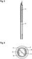
- FIG. 5 It can be seen first of all that a sheet metal or plastic part is used to provide a different intensity of winding or density of the electric heating element in certain zones.
- a sheet metal or plastic part In the upper area of the holder 4, tight connections of the heating element 3 can be seen, while below it is only laid approximately parallel to the direction of extension of the holder.
- the outer bends of the holder 4 are such that the windings of the heating element 5, for example, lie on the inside of the channel 3 of the condensate channel casing 2 and lateral passages 8 for the condensate are provided between the condensate channel casing 2 and the holder 4. This is in Figure 6 illustrated.
Landscapes
- Engineering & Computer Science (AREA)
- Chemical & Material Sciences (AREA)
- Combustion & Propulsion (AREA)
- Mechanical Engineering (AREA)
- General Engineering & Computer Science (AREA)
- Devices For Blowing Cold Air, Devices For Blowing Warm Air, And Means For Preventing Water Condensation In Air Conditioning Units (AREA)
Abstract
Description
- Die Erfindung betrifft Kondensatabführungsvorrichtungen, insbesondere für Lüftungsanlagen, Klimaanlagen oder, ganz besonders bevorzugt, für Wärmepumpen.
- Bei den hier genannten Aggregaten, nämlich Lüftungsanlagen, Klimaanlagen und Wärmepumpen, bildet sich immer, wenn Luft mit einem ausreichenden Feuchtigkeitsgehalt sich daran abkühlt, ein Kondensat, welches abgeführt werden muss. Dieses Phänomen tritt insbesondere bei außen aufgestellten Lüftungsanlagen, Klimaanlagen und Wärmepumpen auf. Das Kondensat entsteht auch an den Außenseiten von Klima-, Wärmepumpen- und Lüftungsleitungen. Ein solches Verhalten ist insbesondere dann festzustellen, wenn warme Luft die kühlen Leitungsoberflächen berührt. Die größten Kondensatmengen entstehen beim Abtauvorgang der Geräte, wodurch eine Schwallbildung entsteht. Daraus ergibt sich in besonderem Maße die Gefahr des Einfrierens und/oder einer Verstopfung des Kondensatkanals.
- Die anfallende Flüssigkeit lässt sich über einen sogenannten Kondensatablauf entsorgen. Hierfür ist es insbesondere bekannt, einen Schlauch mit einen innenliegenden Heizkabel vorzusehen, mit dem das Kondensat ins Erdreich eingeleitet werden kann. Das Heizkabel hat dabei die Funktion, den Ablaufschlauch frostfrei zu halten, also einem Vereisen des Kondensats entgegenzuwirken, und zudem das Kondensat in einen frostfreien Bereich des Erdreichs einzuleiten.
- Aus diversen Anwendungen wurde erkannt, dass ein solcher Ablaufschlauch gelegentlich durch Laub, Tiere und/oder falsche Verlegung im Boden verstopfen kann. Außerdem ist festzustellen, dass die vorgeschlagenen Ablaufschläuche bzw. Heizkabel in der Regel nicht UV-beständig und/oder nicht beständig gegen Nagetiere etc. sind. Zudem ist auch die Anordnung des innenliegenden Heizkabels teilweise mit Problemen behaftet, sodass eine elektrische Sicherheit nicht immer gewährleistet ist.
- Die vorgeschlagenen Konzepte sind häufig bauseitig sehr aufwändig. Es besteht ein hohes Risiko für Fehler, insbesondere eine falsche Montage. Darüber hinaus werden die Ablaufschläuche mit innenliegendem Heizkabel in nur beschränkter Auswahl hinsichtlich ihrer Länge und ihrer Heizmöglichkeiten angeboten. Zudem fehlt es vielfach auch an einer Drainagefunktion, die gegebenenfalls durch externe Maßnahmen sichergestellt werden. Dies kann allerdings zu einem Rückstau in dem Ablaufschlauch führen, was gegebenenfalls sogar zu einer Gerätebeschädigung durch Vereisung führen kann.
- Hiervon ausgehend ist es Aufgabe der vorliegenden Erfindung, die mit Bezug auf den Stand der Technik geschilderten Probleme zumindest teilweise zu lösen. Insbesondere soll eine Kondensatabführvorrichtung angegeben werden, die einfach und sicher ist sowie an den jeweiligen baulichen Gegebenheiten besonders einfach anpassbar sein soll.
- Diese Aufgaben werden gelöst mit einer Kondensatabführvorrichtung gemäß den Merkmalen des Patentanspruchs 1. Vorteilhafte Weiterbildungen sind in den abhängigen Patentansprüchen angegeben. Es ist darauf hinzuweisen, dass die in den Patentansprüchen einzeln aufgeführten Merkmale in beliebiger, technologisch sinnvoller Weise miteinander kombiniert werden können. Die Beschreibung, insbesondere in Zusammenhang mit den Figuren, erläutert die Erfindung und gibt zusätzliche Ausführungsbeispiele an.
- Hierzu trägt eine Kondensatabführvorrichtung bei, die zumindest Folgendes umfasst: einen Kondensatkanalmantel mit einem innenliegenden Kanal,
- eine Halterung, die in den Kanal einführbar ist,
- mindestens ein elektrisches Heizelement, das an der Halterung fixierbar ist, und
- ein Anschlusselement zur Fixierung des Kondensatkanalmantels an einer Kondensatauffangwanne.
- Die Kondensatabführvorrichtung ist insbesondere nach Art eines Bausatzes verfügbar und insbesondere eingerichtet, mit einem standardisierten Anschlusselement gegebenenfalls an unterschiedliche Ausführungsvarianten oder Aggregate aus der Gruppe Lüftungsanlagen, Klimaanlage und insbesondere Wärmepumpen angeschlossen zu werden.
- Es ist bevorzugt, dass die Kondensatabführvorrichtung einen einzelnen Kondensatkanalmantel aufweist. Der Kondensatkanalmantel kann insbesondere formsteif bzw. formstabil ausgeführt sein. Ganz besonders bevorzugt ist dieser mit einem UV-beständigen Material gebildet. Zudem ist bevorzugt, dass der Kondensatkanalmantel eine Struktur und/oder ein Material umfasst, das diesen gegen Beschädigungen durch Nagetiere weitgehend schützt. Hierfür kann hilfreich sein, dass der Kondensatkanalmantel mit einer Schutzschicht, einem Schutzgitter oder dergleichen versehen ist. Es ist weiter möglich, dass der Kondensatkanalmantel eine ausreichende Manteldicke hat, sodass es gerade durch Befall durch Nagetiere nicht möglich ist, den innenliegenden Kanal zu erreichen. Der innenliegende Kanal dient insbesondere zur Weiterleitung von Kondensat, einer zumindest teilweisen Aufnahme der Halterung und/oder des elektrischen Heizelementes und/oder weiterer Komponenten der Kondensatabführvorrichtung.
- Die Halterung ist bevorzugt einteilig ausgeführt. Es ist möglich, dass diese mit einem anderen Material bereitgestellt wird als der Kondensatkanalmantel. Bevorzugt ist die Halterung mit Metall gebildet. Die Halterung ist so dimensioniert, dass diese in den Kanal des Kondensatkanalmantels einführbar ist. Insbesondere ist sie so gestaltet, dass sie vollständig in den Kanal aufgenommen werden kann. Ganz bevorzugt erstreckt sich die Halterung diagonal nahezu oder vollständig über den Kanaldurchmesser.
- Zudem ist die Halterung so ausgestaltet, dass dort mindestens ein elektrisches Heizelement fixierbar ist. Bevorzugt ist, dass ein einzelnes elektrisches Heizelement nach Art oder in Form eines Heizkabels vorgesehen ist. Das längliche Heizkabel bzw. das mindestens eine elektrische Heizelement kann an diversen Halterungspunkten positionsgenau und/oder dauerhaft an der Halterung und/oder im Kanal des Kondensatkanalmantels fixiert werden. So ist beispielsweise möglich, dass die Halterung mit entsprechenden Aufnahmen oder Aussparungen versehen ist, in die formschlüssig und gegebenenfalls auch kraftschlüssig das mindestens eine elektrische Heizelement eingebracht werden kann, welches somit lagefixiert ist.
- Das Anschlusselement zur Fixierung des Kondensatkanalmantels an einer Kondensatauffangwanne ist bevorzugt nahe einem Ende des Kondensatkanalmantels anordenbar bzw. angeordnet. Es ist möglich, dass das Anschlusselement den Kondensatkanalmantel zumindest teilweise umgibt. Es ist möglich, dass das Anschlusselement so gestaltet ist, dass sich das mindestens eine elektrische Heizelement und/oder dessen elektrische Versorgungsleitung dort hindurcherstreckt.
- Der Kondensatkanalmantel kann als Rohr ausgebildet sein. Das Rohr hat insbesondere einen wesentlichen kreisrunden Querschnitt. Das Rohr kann mit aussteifenden Rillen und/oder Rippen ausgeführt sein. Das Rohr kann mit Metall oder einem beständigen Kunststoff gebildet sein. Das Rohr hat im Wesentlichen eine einzige (gerade verlaufende) Erstreckungsrichtung und ist nicht oder nur in beschränktem Umfang elastisch verformbar.
- Die Halterung kann einen innenliegenden Durchlass für Kondensat aufweisen. Es ist alternativ auch möglich, dass die Halterung einen lateralen Durchlass für Kondensat mit dem Kondensatkanalmantel bilden kann. Im erstgenannten Fall könnte die Halterung so geformt sein, dass sie einen ausschließlich von der Halterung begrenzten Durchlass bildet, der sich über die gesamte Erstreckung der Halterung ausdehnen kann. Gemäß der weiteren Alternative kann vorgesehen sein, dass die Halterung so gestaltet ist, dass sie, insbesondere beidseits zu planen Mittelflächen, jeweils einen lateralen Durchlass für Kondensat bildet, dann jeweils gemeinsam mit der angrenzenden Innenoberfläche des Kondensatkanalmantels.
- Die Halterung kann mit einem Blechteil gebildet sein. Es ist möglich, dass die Halterung nur mit einem einzelnen Blechteil gebildet ist. Es ist möglich, dass das Blechteil ein umgeformtes Stanzblech ist. Es ist möglich, dass die Halterung stabförmig ausgebildet ist.
- Das mindestens eine elektrische Heizelement ist mittels der Halterung hin zum Kondensatkanalmantel ausrichtbar. Dies bedeutet insbesondere, dass die Halterung bzw. die Platzierung des mindestens einen elektrischen Heizelements an der Halterung zu einer ausgerichteten Positionierung des Heizelements in einem vorbestimmten Bereich des Kondensatkanalmantel ermöglicht ist. Hierfür ist möglich, dass die Halterung an dem Kondensatkanalmantel, dem Anschlusselement und/oder der Kondensatauffangwanne ausrichtbar ist, wodurch gleichzeitig auch das mindestens eine elektrische Heizelement zum Kondensatkanalmantel positionsgenau angeordnet ist.
- Die Anordnung des mindestens einen elektrischen Heizelements kann so vorgesehen sein, dass dieses über dessen Erstreckungsabschnitt im Kondensatkanalmantel eine verschiedene Heizleistung abgeben kann. Für die in den gegebenenfalls verschiedenen Zonen verschieden einstellbare oder eingerichtete Heizleistung ist insbesondere die Anordnung des mindestens einen elektrischen Heizelementes ausschlaggebend. Dies meint insbesondere, dass das mindestens eine elektrische Heizelement üblicherweise über seine Außenoberfläche eine oberflächenspezifisch gleiche Heizleistung abgibt, aber aufgrund einer konzentrierten oder weiter entfernten Anordnung von Teilbereichen und/oder einer Anzahl des mindestens einen elektrischen Heizelements ist die verschiedene Heizleistung eingestellt. Beispielsweise ist möglich, dass das elektrische Heizelement nach Art eines Heizkabels um die Halterung gewickelt ist, wobei die Dichte bzw. der Neigungswinkel der Wicklung variiert ist. Werden mehrere elektrische Heizelemente vorgesehen, so können diese mit einer kleineren und/oder einem größeren Abstand zueinander positioniert werden, um in dem Erstreckungsabschnitt unterschiedliche Heizleistungen einzustellen.
- Das Anschlusselement kann einen lösbaren Klemmverschluss umfassen. Das Anschlusselement kann damit an dem Kondensatkanalmantel und/oder der Kondensatauffangwanne befestigt sein. Der lösbare Klemmverschluss kann so gestaltet sein, dass zwei zueinander relativ bewegbare Teile vorgesehen sind, die so miteinander verspannt werden können, dass das Anschlusselement an dem Kondensatkanalmantel und/oder der Kondensatauffangwanne fixiert ist.
- Das Anschlusselement kann eine Abdichtung hin zur Kondensatauffangwanne umfassen. Hierfür kann die Abdichtung so an dem Anschlusselement vorgesehen sein, dass diese, gegebenenfalls stirnseitig, hin zu der Kondensatauffangwanne anliegt und so eine Dichtungsfunktion erfüllt.
- Gegenüberliegend zum Anschlusselement sowie am und/oder im Kondensatkanalmantel ist ein Drainagedeckel fixierbar, der einen Abschluss des innenliegenden Kanals bildet. Der Drainagedeckel kann als separates Bauteil ausgeführt sein, welches, gegebenenfalls lösbar, am gegenüberliegenden Ende des Kondensatkanalmantels anordenbar ist. Der Drainagedeckel überspannt den innenliegenden Kanal, wodurch ein Abschluss gebildet ist. Der Drainagedeckel kann nach Art eines Topfes ausgeführt sein. Der Drainagedeckel kann eine Vielzahl von Poren aufweisen, durch die Kondensat austreten kann.
- Es ist möglich, dass ein Erstreckungsabschnitt des mindestens einen elektrischen Heizelements im Kondensatkanalmantel mindestens 20 % kleiner ist als eine Länge des Kondensatkanalmantels. Damit ist insbesondere gemeint, dass sich das mindestens eine elektrische Heizelement ausgehend von dem Anschlusselement nicht über die gesamte Länge des Kondensatkanalmantels erstreckt. Insbesondere ist die Fixierung an der Halterung so vorgesehen, dass das mindestens eine elektrische Heizelement nur einen Teilbereich der Länge den Kondensatkanalmantels erreicht bzw. wärmen kann. Es ist möglich, dass für den Fall, dass die Kondensatabführvorrichtung im Boden platziert wird, die Überlänge des Kondensatkanalmantels gekürzt wird, sodass gegebenenfalls in der erhältlichen Set-Variante die Überlänge des Kondensatkanalmantels auch mehr als 20 % betragen kann, insbesondere z. B. mindestens 30 % oder sogar 40 %.
- Gemäß einem weiteren Aspekt der Erfindung wird eine Kondensatabführvorrichtung in der hier beschriebenen Art zur sicheren Einleitung von Kondensat einer Lüftungsanlage, Klimaanlage und/oder Wärmepumpe in den Boden vorgeschlagen.
- Mit der hier vorgeschlagenen Kondensatabführvorrichtung ist ein vorkonfektioniertes System angegeben, welches zum einen eine Toleranzausgleich ermöglicht und zum anderen eine variable Heizzonengestaltung.
- Der Kondensatkanalmantel kann nach Art eines Drainagerohres ausgebildet sein, mit innenliegender Rohrbegleitheizung (mindestens ein elektrisches Heizelement). Die Heizleistung kann außerhalb des Kondensatkanalmantels eingestellt werden, wobei innerhalb des Kondensatkanalmantels durch eine individuelle Wicklung an den gewünschten Stellen eine fokussierte Erhitzung ermöglicht ist.
- Das Anschlusselement kann als eine Art Universalanschluss an ein Bodenblech eines hier beschriebenen Aggregats eingesetzt werden.
- Insofern ist dieses System individuell auf eine vorgegebene bzw. eine gewünschte Länge einzustellen bzw. kürzbar. Weiter ist es insbesondere ausgelegt für eine vertikale Kondensatabführung (das ist der Standardinstallationsfall). Zudem ist der Kondensatkanalmantel UV-beständig, weist einen Nagetierschutz auf, und ist elektrisch sicher durch eine berührungslose, innere Verlegung der Heizelemente.
- Hier wird auch ein Verfahren zur Montage einer Kondensatabführvorrichtung der hier beschriebenen Art zu einem Aggregat erläutert. Dieses Montageverfahren kann beispielsweise folgende Schritte umfassen:
- a) Zunächst wird der vorkonfektionierte Kondensatkanalmantel entsprechend den Gegebenheiten auf eine gewünschte Länge gekürzt.
- b) Auch die Halterung kann gegebenenfalls entsprechend den Gegebenheiten vor Ort auf eine vorgegebene Erstreckungslänge gekürzt werden.
- c) Weiter ist nun möglich, das mindestens eine elektrische Heizelement, bevorzugt ein Heizkabel, so an bzw. um die Halterung zu positionieren bzw. wickeln, dass besonders "kalte Zonen" (z. B. direkt unterhalb des Aggregats an der Umgebungsluft und/oder im oberen Bereich des Bodens) eine größere Anzahl bzw. größere Wicklungszahl aufweist, als in anderen Bereichen.
- d) Die Halterung kann mit dem daran befestigten mindestens einen elektrischen Heizelement bzw. dem dort aufgewickelten Heizkabel in den Kondensatkanalmantel eingeführt werden, wobei die Halterung insbesondere so gestaltet ist, dass diese eine geführte translatorische Bewegung innerhalb des Kanals ausführen kann. Zudem kann der Drainagedeckel aufgesteckt werden.
- e) Die Kondensatabführvorrichtung bzw. soweit diese vorbereitet ist, kann nun in eine bereitgestellte Sickergrube gesteckt werden und von unten an das Aggregat bzw. die Kondensatauffangwanne des Aggregats befestigt werden.
- f) Die elektrische Stromversorgung hin zu dem mindestens einen elektrischen Heizelement kann innerhalb des Aggregates verlegt werden und dort beispielweise an eine Stromquelle bzw. Platine angeschlossen werden.
- g) Das Anschlusselement kann nun aufgesteckt bzw. fixiert werden.
- Die Erfindung sowie das technische Umfeld werden nachfolgend anhand der Figuren näher erläutert. Es ist darauf hinzuweisen, dass die in den Figuren gezeigten Bauteile Ausführungsbeispiele sind, auf die die Erfindung nicht beschränkt ist. Insbesondere sind die Figuren schematischer Natur und können nicht zur exakten Dimensionierung herangezogen werden.
-
Fig. 1 zeigt eine Kondensatabführvorrichtung 1 im montierten Zustand unterhalb eines Aggregats 14. Zu erkennen ist unten der Boden 15, in dem eine Sickergrube eingebracht ist, indem der Kondensatkanalmantel 2 positioniert ist. Der Kondensatkanalmantel 2 hat einen innenliegenden Kanal 3, in dem eine wendelförmiges elektrisches Heizelement 5 vorgesehen ist. Dieses elektrische Heizelement 5 ist auf einer angedeuteten Halterung 4 lagegerecht positioniert. Der Kondensatkanalmantel 2 ist mittels eines Anschlusselementes 6 an einer Kondensatauffangwanne 7 des Aggregats 14 fixiert. Ebenso ist angedeutet, dass die Stromversorgung des elektrischen Heizelements 5 sich in das Aggregat erstreckt, nämlich bis hin zu einem Stromanschluss 16 im Inneren des Gehäuses 17 des Aggregats 14. -
Fig. 2 zeigt ein Set zur Bereitstellung einer hier vorgeschlagenen Kondensatabführvorrichtung 1. Dieses umfasst einen Kondensatkanalmantel 2 mit einem innenliegenden Kanal 3, der gegenüberliegende zwei Enden hat, wobei an dem einen Ende ein Anschlusselement 6 zur Fixierung des Kondensatkanalmantels 2 an einer Kondensatauffangwanne 7 vorgesehen ist und auf der anderen Seite ein Drainagedeckel 11 fixierbar ist. Rechts daneben ist die Halterung 4 nach Art eines Blechbauteils dargestellt, wobei dieses radial gegenüberliegend der Umbiegungen mit Aussparungen aufweist und einer zentralen planen Fläche. Die zentrale plane Fläche kann zur Abgrenzung zweier lateraler Durchlässe genutzt werden. Weiter rechts ist ein kabelförmiges elektrisches Heizelement 5 vorgesehen, welches ohne die Halterung 4 entsprechend der Teilung der Aussparungen im Blechteil aufgewickelt werden kann. Zudem ist ein Anschlusselement angedeutet, welches hier eine Dichtung 10 umfasst. -
Fig. 3 zeigt ein anderes Ausführungsbeispiel, wobei der Kondensatkanalmantel 2 mittels des Anschlusselementes 6, welches in diesem Fall nach Art eines lösbaren Klemmverschlusses 9 ausgeführt ist, an der Kondensatauffangwanne 7 exemplarisch fixiert ist. Es ist weiter zu erkennen, dass ein Erstreckungsabschnitt 12 des mindestens einen elektrischen Heizelements 5 im Kondensatkanalmantel 2 mindestens 20 % kleiner als die Länge 13 des Kondensatkanalmantels 2 ist. -
Fig. 4 zeigt ein Ausführungsbeispiel eines Drainagedeckels 11, der zur Fixierung an dem Kondensatkanalmantel 2 mit einem passenden Kragen 19 ausgeführt ist, und der im Übrigen eine Vielzahl von Poren 18 aufweist. - Schließlich noch ein Detail einer Halterung mit einem kabelähnlichen Heizelement, welches mit den
Figuren 5 und 6 veranschaulicht ist. InFigur 5 ist zunächst zu erkennen, dass ein Blech- oder Kunststoffteil genutzt wird, um in bestimmten Zonen eine unterschiedlich intensive Wicklung oder Dichte vom elektrischen Heizelement vorzusehen. Im oberen Bereich der Halterung 4 sind enge Bindungen des Heizelements 3 zu erkennen, während es darunter nur etwa parallel zur Erstreckungsrichtung der Halterung verlegt ist. Die äußeren Biegungen der Halterung 4 sind der Art, dass die Wicklungen des Heizelementes 5 beispielsweise innen am Kanal 3 des Kondensatkanalmantels 2 anliegen und zwischen dem Kondensatkanalmantel 2 und der Halterung 4 laterale Durchlässe 8 für das Kondensat vorgesehen sind. Dies ist inFigur 6 veranschaulicht. -
- 1
- Kondensatabführvorrichtung
- 2
- Kondensatkanalmantel
- 3
- Kanal
- 4
- Halterung
- 5
- elektrisches Heizelement
- 6
- Anschlusselement
- 7
- Kondensatauffangwanne
- 8
- Durchlass
- 9
- Klemmverschluss
- 10
- Abdichtung
- 11
- Drainagedeckel
- 12
- Erstreckungsabschnitt
- 13
- Länge
- 14
- Aggregat
- 15
- Boden
- 16
- Stromanschluss
- 17
- Gehäuse
- 18
- Pore
- 19
- Kragen
Claims (11)
- Kondensatabführvorrichtung (1), zumindest umfassend einen Kondensatkanalmantel (2) mit einem innenliegenden Kanal (3), eine Halterung (4), die in dem Kanal (3) einführbar ist, mindestens ein elektrisches Heizelement (5), das an der Halterung (4) fixierbar ist und ein Anschlusselement (6) zur Fixierung des Kondensatkanalmantels (2) an einer Kondensatauffangwanne (7).
- Kondensatabführvorrichtung (1) nach Anspruch 1, dadurch gekennzeichnet, dass der Kondensatkanalmantel (2) ein Rohr ist.
- Kondensatabführvorrichtung (1) nach einem der vorhergehenden Ansprüche,
dadurch gekennzeichnet, dass die Halterung (4) einen innenliegenden Durchlass (8) für Kondensat aufweist oder einen lateralen Durchlass (8) für Kondensat mit dem Kondensatkanalmantel (2) bilden kann. - Kondensatabführvorrichtung (1) nach einem der vorhergehenden Ansprüche,
dadurch gekennzeichnet, dass die Halterung (4) mit einem Blechteil gebildet ist. - Kondensatabführvorrichtung (1) nach einem der vorhergehenden Ansprüche,
dadurch gekennzeichnet, dass das mindestens eine elektrische Heizelement (5) mittels der Halterung (4) hin zum Kondensatkanalmantel (2) ausrichtbar ist. - Kondensatabführvorrichtung (1) nach einem der vorhergehenden Ansprüche,
dadurch gekennzeichnet, dass eine Anordnung des mindestens einen elektrischen Heizelements (5) vorgesehen ist, so dass dieses über dessen Erstreckungsabschnitt (12) im Kondensatkanalmantel (2) eine verschiedene Heizleistung abgeben kann. - Kondensatabführvorrichtung (1) nach einem der vorhergehenden Ansprüche,
dadurch gekennzeichnet, dass das Anschlusselement (6) einen lösbaren Klemmverschluss (9) umfasst. - Kondensatabführvorrichtung (1) nach einem der vorhergehenden Ansprüche,
dadurch gekennzeichnet, dass das Anschlusselement (6) eine Abdichtung (10) hin zur Kondensatauffangwanne (7) umfasst. - Kondensatabführvorrichtung (1) nach einem der vorhergehenden Ansprüche,
dadurch gekennzeichnet, dass gegenüberliegend zum Anschlusselement (6) sowie am/im Kondensatkanalmantel (2) ein Drainagedeckel (11) fixierbar ist, der einen Abschluss des innenliegenden Kanals (3) bildet. - Kondensatabführvorrichtung (1) nach einem der vorhergehenden Ansprüche,
dadurch gekennzeichnet, dass ein Erstreckungsabschnitt (12) des mindestens einen elektrischen Heizelements (5) im Kondensatkanalmantel (2) mindestens 20 % kleiner ist als eine Länge (13) des Kondensatkanalmantels (2). - Verwendung einer Kondensatabführvorrichtung (1) nach einem der vorhergehenden Ansprüche zur sichern Einleitung von Kondensat einer Lüftungsanlage, Klimaanlage und/oder Wärmepumpe in einen Boden.
Applications Claiming Priority (1)
| Application Number | Priority Date | Filing Date | Title |
|---|---|---|---|
| DE102022126167.0A DE102022126167A1 (de) | 2022-10-10 | 2022-10-10 | Kondensatabführvorrichtung und Wärmepumpe |
Publications (3)
| Publication Number | Publication Date |
|---|---|
| EP4354040A1 true EP4354040A1 (de) | 2024-04-17 |
| EP4354040B1 EP4354040B1 (de) | 2025-08-20 |
| EP4354040C0 EP4354040C0 (de) | 2025-08-20 |
Family
ID=88204150
Family Applications (1)
| Application Number | Title | Priority Date | Filing Date |
|---|---|---|---|
| EP23199733.9A Active EP4354040B1 (de) | 2022-10-10 | 2023-09-26 | Kondensatabführvorrichtung und deren verwendung |
Country Status (2)
| Country | Link |
|---|---|
| EP (1) | EP4354040B1 (de) |
| DE (1) | DE102022126167A1 (de) |
Citations (2)
| Publication number | Priority date | Publication date | Assignee | Title |
|---|---|---|---|---|
| DE102007046009A1 (de) * | 2006-09-29 | 2008-09-04 | Denso Corp., Kariya | Wärmepumpeneinrichtung und im Freien anzuordnende Einheit für dieselbe |
| EP2354694A2 (de) * | 2010-02-08 | 2011-08-10 | Haven Limited | Frostschutzsystem für ein Kondensatabflussrohr |
-
2022
- 2022-10-10 DE DE102022126167.0A patent/DE102022126167A1/de active Pending
-
2023
- 2023-09-26 EP EP23199733.9A patent/EP4354040B1/de active Active
Patent Citations (2)
| Publication number | Priority date | Publication date | Assignee | Title |
|---|---|---|---|---|
| DE102007046009A1 (de) * | 2006-09-29 | 2008-09-04 | Denso Corp., Kariya | Wärmepumpeneinrichtung und im Freien anzuordnende Einheit für dieselbe |
| EP2354694A2 (de) * | 2010-02-08 | 2011-08-10 | Haven Limited | Frostschutzsystem für ein Kondensatabflussrohr |
Also Published As
| Publication number | Publication date |
|---|---|
| DE102022126167A1 (de) | 2024-04-11 |
| EP4354040B1 (de) | 2025-08-20 |
| EP4354040C0 (de) | 2025-08-20 |
Similar Documents
| Publication | Publication Date | Title |
|---|---|---|
| DE102010049015B4 (de) | Kühlflüssigkeits-Verteilerschlauch und Batterieanordnung | |
| DE202016004862U1 (de) | Abgeschirmter Drahtstrang und Abschirmungselement | |
| EP3499145B1 (de) | Anordnung einer vorrichtung zur temperierung eines raumes an einer decke des raumes | |
| EP0333906A1 (de) | Kaltleiter-PTC-Heizkörper | |
| DE202017104318U1 (de) | Klemme mit Installationsbestätigungsanzeige zum Sichern einer fluidführenden Leitung an einem Schaumstoffeil | |
| DE20021614U1 (de) | Fußbodenheizung | |
| DE102017111525A1 (de) | Fahrzeug mit mindestens einer Kanalvorrichtung und Verfahren zum Ausrüsten eines Fahrzeugs mit einer Kanalvorrichtung | |
| EP4354040B1 (de) | Kondensatabführvorrichtung und deren verwendung | |
| AT506308B1 (de) | Befestigungsvorrichtung und verfahren zum anschluss hydraulischer leitungen | |
| EP2375182B1 (de) | Wanddurchführung für eine innen aufstellbare Wärmepumpenanlage | |
| DE102012206076A1 (de) | Stromschienensystem | |
| WO2011009753A1 (de) | Endstück für einen wellschlauch und teilesatz mit einem solchen endstück | |
| EP1610049B1 (de) | Schlauchverbindungssystem für einen beheizbaren Schlauch | |
| EP3933284A1 (de) | Heiz- oder kühlkörper, insbesondere mehrreihiger flachheizkörper oder heizwand in vertikaler oder horizontaler anordnung, mit mindestens einer lüfterbaugruppe | |
| DE102024124774B4 (de) | Abdeckungsvorrichtung zum Abdecken einer Dachöffnung | |
| DE9002321U1 (de) | Ventilator | |
| DE102014012873A1 (de) | Verbindungselement zum elektrischen Verbinden von Flachleitern | |
| DE20021612U1 (de) | Fußbodenheizung | |
| EP2182268A1 (de) | Heiz- oder Kühlanordnung für eine Rohrleitung | |
| DE102016218723A1 (de) | Einrichtung zum Ausgleich von Längenänderungen von Kunststoffrohren | |
| DE102016115343B4 (de) | Wärmespeicher | |
| DE102016225471A1 (de) | Handbremsseil | |
| EP1413833B1 (de) | Führungsprofil und Konvektor | |
| DE60116245T2 (de) | Klammer für elektrische Kabel | |
| AT403180B (de) | Abdeckelement |
Legal Events
| Date | Code | Title | Description |
|---|---|---|---|
| PUAI | Public reference made under article 153(3) epc to a published international application that has entered the european phase |
Free format text: ORIGINAL CODE: 0009012 |
|
| STAA | Information on the status of an ep patent application or granted ep patent |
Free format text: STATUS: THE APPLICATION HAS BEEN PUBLISHED |
|
| AK | Designated contracting states |
Kind code of ref document: A1 Designated state(s): AL AT BE BG CH CY CZ DE DK EE ES FI FR GB GR HR HU IE IS IT LI LT LU LV MC ME MK MT NL NO PL PT RO RS SE SI SK SM TR |
|
| STAA | Information on the status of an ep patent application or granted ep patent |
Free format text: STATUS: REQUEST FOR EXAMINATION WAS MADE |
|
| 17P | Request for examination filed |
Effective date: 20241011 |
|
| RBV | Designated contracting states (corrected) |
Designated state(s): AL AT BE BG CH CY CZ DE DK EE ES FI FR GB GR HR HU IE IS IT LI LT LU LV MC ME MK MT NL NO PL PT RO RS SE SI SK SM TR |
|
| GRAP | Despatch of communication of intention to grant a patent |
Free format text: ORIGINAL CODE: EPIDOSNIGR1 |
|
| STAA | Information on the status of an ep patent application or granted ep patent |
Free format text: STATUS: GRANT OF PATENT IS INTENDED |
|
| RIC1 | Information provided on ipc code assigned before grant |
Ipc: F24F 13/22 20060101AFI20250313BHEP |
|
| INTG | Intention to grant announced |
Effective date: 20250401 |
|
| GRAS | Grant fee paid |
Free format text: ORIGINAL CODE: EPIDOSNIGR3 |
|
| GRAA | (expected) grant |
Free format text: ORIGINAL CODE: 0009210 |
|
| STAA | Information on the status of an ep patent application or granted ep patent |
Free format text: STATUS: THE PATENT HAS BEEN GRANTED |
|
| AK | Designated contracting states |
Kind code of ref document: B1 Designated state(s): AL AT BE BG CH CY CZ DE DK EE ES FI FR GB GR HR HU IE IS IT LI LT LU LV MC ME MK MT NL NO PL PT RO RS SE SI SK SM TR |
|
| REG | Reference to a national code |
Ref country code: GB Ref legal event code: FG4D Free format text: NOT ENGLISH |
|
| REG | Reference to a national code |
Ref country code: CH Ref legal event code: EP |
|
| REG | Reference to a national code |
Ref country code: IE Ref legal event code: FG4D Free format text: LANGUAGE OF EP DOCUMENT: GERMAN |
|
| REG | Reference to a national code |
Ref country code: DE Ref legal event code: R096 Ref document number: 502023001617 Country of ref document: DE |
|
| U01 | Request for unitary effect filed |
Effective date: 20250820 |
|
| U07 | Unitary effect registered |
Designated state(s): AT BE BG DE DK EE FI FR IT LT LU LV MT NL PT RO SE SI Effective date: 20250828 |
|
| U20 | Renewal fee for the european patent with unitary effect paid |
Year of fee payment: 3 Effective date: 20250903 |
|
| PG25 | Lapsed in a contracting state [announced via postgrant information from national office to epo] |
Ref country code: IS Free format text: LAPSE BECAUSE OF FAILURE TO SUBMIT A TRANSLATION OF THE DESCRIPTION OR TO PAY THE FEE WITHIN THE PRESCRIBED TIME-LIMIT Effective date: 20251220 |
|
| PG25 | Lapsed in a contracting state [announced via postgrant information from national office to epo] |
Ref country code: NO Free format text: LAPSE BECAUSE OF FAILURE TO SUBMIT A TRANSLATION OF THE DESCRIPTION OR TO PAY THE FEE WITHIN THE PRESCRIBED TIME-LIMIT Effective date: 20251120 |
|
| PG25 | Lapsed in a contracting state [announced via postgrant information from national office to epo] |
Ref country code: HR Free format text: LAPSE BECAUSE OF FAILURE TO SUBMIT A TRANSLATION OF THE DESCRIPTION OR TO PAY THE FEE WITHIN THE PRESCRIBED TIME-LIMIT Effective date: 20250820 |
|
| PG25 | Lapsed in a contracting state [announced via postgrant information from national office to epo] |
Ref country code: GR Free format text: LAPSE BECAUSE OF FAILURE TO SUBMIT A TRANSLATION OF THE DESCRIPTION OR TO PAY THE FEE WITHIN THE PRESCRIBED TIME-LIMIT Effective date: 20251121 |
|
| PG25 | Lapsed in a contracting state [announced via postgrant information from national office to epo] |
Ref country code: PL Free format text: LAPSE BECAUSE OF FAILURE TO SUBMIT A TRANSLATION OF THE DESCRIPTION OR TO PAY THE FEE WITHIN THE PRESCRIBED TIME-LIMIT Effective date: 20250820 |
|
| PG25 | Lapsed in a contracting state [announced via postgrant information from national office to epo] |
Ref country code: RS Free format text: LAPSE BECAUSE OF FAILURE TO SUBMIT A TRANSLATION OF THE DESCRIPTION OR TO PAY THE FEE WITHIN THE PRESCRIBED TIME-LIMIT Effective date: 20251120 |
|
| PG25 | Lapsed in a contracting state [announced via postgrant information from national office to epo] |
Ref country code: ES Free format text: LAPSE BECAUSE OF FAILURE TO SUBMIT A TRANSLATION OF THE DESCRIPTION OR TO PAY THE FEE WITHIN THE PRESCRIBED TIME-LIMIT Effective date: 20250820 |
|
| PG25 | Lapsed in a contracting state [announced via postgrant information from national office to epo] |
Ref country code: SM Free format text: LAPSE BECAUSE OF FAILURE TO SUBMIT A TRANSLATION OF THE DESCRIPTION OR TO PAY THE FEE WITHIN THE PRESCRIBED TIME-LIMIT Effective date: 20250820 |
|
| PG25 | Lapsed in a contracting state [announced via postgrant information from national office to epo] |
Ref country code: CZ Free format text: LAPSE BECAUSE OF FAILURE TO SUBMIT A TRANSLATION OF THE DESCRIPTION OR TO PAY THE FEE WITHIN THE PRESCRIBED TIME-LIMIT Effective date: 20250820 |
|
| PG25 | Lapsed in a contracting state [announced via postgrant information from national office to epo] |
Ref country code: SK Free format text: LAPSE BECAUSE OF FAILURE TO SUBMIT A TRANSLATION OF THE DESCRIPTION OR TO PAY THE FEE WITHIN THE PRESCRIBED TIME-LIMIT Effective date: 20250820 |