EP4353433B1 - Hybride formvibration - Google Patents
Hybride formvibration Download PDFInfo
- Publication number
- EP4353433B1 EP4353433B1 EP22213854.7A EP22213854A EP4353433B1 EP 4353433 B1 EP4353433 B1 EP 4353433B1 EP 22213854 A EP22213854 A EP 22213854A EP 4353433 B1 EP4353433 B1 EP 4353433B1
- Authority
- EP
- European Patent Office
- Prior art keywords
- mold
- frame
- vibration
- pallet
- vibration frame
- Prior art date
- Legal status (The legal status is an assumption and is not a legal conclusion. Google has not performed a legal analysis and makes no representation as to the accuracy of the status listed.)
- Active
Links
Images


Classifications
-
- B—PERFORMING OPERATIONS; TRANSPORTING
- B28—WORKING CEMENT, CLAY, OR STONE
- B28B—SHAPING CLAY OR OTHER CERAMIC COMPOSITIONS; SHAPING SLAG; SHAPING MIXTURES CONTAINING CEMENTITIOUS MATERIAL, e.g. PLASTER
- B28B1/00—Producing shaped prefabricated articles from the material
- B28B1/08—Producing shaped prefabricated articles from the material by vibrating or jolting
- B28B1/087—Producing shaped prefabricated articles from the material by vibrating or jolting by means acting on the mould ; Fixation thereof to the mould
- B28B1/0873—Producing shaped prefabricated articles from the material by vibrating or jolting by means acting on the mould ; Fixation thereof to the mould the mould being placed on vibrating or jolting supports, e.g. moulding tables
Definitions
- This application relates generally to concrete product manufacturing devices.
- Concrete products machines generally include some form of vibration assembly to remove air pockets during the forming of a concrete product.
- Known vibration assemblies may employ vibration means such as rotary vibrations to shake the mold, or impact tables that strike the bottom of the production pallet to induce vibration.
- vibration means such as rotary vibrations to shake the mold, or impact tables that strike the bottom of the production pallet to induce vibration.
- a given product may benefit from one vibration type, while being harmed by another.
- Current vibration technology for concrete products machines uses one or the other type of vibration, which is not optimal for every product.
- US 4,830,597 discloses a vibration assembly in accordance with the preamble of claim 1, more specifically it discloses a vibrator for a concrete block molding machine.
- US 4,238,177 discloses a concrete block molding machine.
- a hybrid vibration assembly comprising a concrete product mold, a vibration frame positioned to transmit vibration to at least a portion of the mold, and a stationary frame carrying the vibration frame.
- the assembly also comprises knocker bars supportable on the stationary frame in positions where, when installed, they carry at least a portion of the mold, a motor operatively connected to a vibrator mounted on the vibration frame, and a mechanical frame/mold clamp positioned and actuable to alternately couple the vibration frame to the mold and decouple the vibration frame from the mold.
- the vibration frame may be positioned to carry at least a portion of the mold.
- the knocker bars may be supportable on the stationary frame for vertical adjustment relative to the stationary frame.
- the motor is not operatively coupled to distribute motion among the knocker bars.
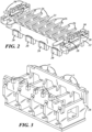
- a hybrid vibration assembly for a concrete products machine is generally shown at 10 in the figures.
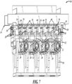
- the assembly 10 comprises one or more motors 12 operatively connected to other components of the vibration assembly 10, so that the motors 12, when actuated, drive at least one vibrator 20 (which may comprise eccentric-weight rotary vibrators) mounted to a vibration frame 22 configured to carry a mold 14 of a concrete products machine, and thereby transmit vibration to the contents of the mold 14.
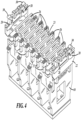
- the motors 12 and the vibration frame 22 may be supported by a stationary frame 18 of the assembly 10 (as best shown by comparing Figs. 2-4 ).
- the motors 12 may be adjusted to change frequency and/or amplitude of the vibrators 20 by changing the speed and/or phase of the eccentric weight vibrators 20.
- the adjustment of the motors 12 may be either manually-adjusted, or via an automated controller programmed to respond to a remote operator input. While the motors are shown supported by stationary frame 18 in the preferred embodiment shown in Figure 7 , in alternate embodiments the motors may be mounted anywhere on or adjacent the assembly 10, and may drive the vibrators directly, or via remote linkages such as flexible driveshafts known in the art.
- the stationary frame 18 may also support removable knocker bars 16.
- the knocker bars 16 may be removably supported on knocker bar mounting points 17 on the stationary frame 18.
- the knocker bar mounting points 17 may permit vertical adjustment of the knocker bars 16 relative to the stationary frame 18.
- the knocker bars 16 may be supportable on the stationary frame 18 in positions where, when installed, they carry at least a portion of the mold 14.
- the knocker bars 16 are preferably not used as agitation implements.
- the motors 12 are optionally not operatively coupled to the knocker bars 16 to distribute motion among the knocker bars 16.
- the vibration frame 22 may be configured to carry, and transmit vibration to, the mold 14 in several different ways depending on the type of vibration desired for the mold 14.
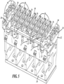
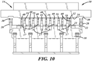
- the vibration frame 22 may include standoffs 26 mounted to an upper vibration frame surface 23.
- the vibration frame standoffs 26 may be configured to support the weight of the mold 14.
- the vibration frame 22 may further comprise frame connection points 28 for one or more mechanical frame/mold clamps 30 configured to alternately couple the vibration frame 22 to the mold 14 and decouple the vibration frame 22 from the mold 14.
- the vibration frame standoffs 26 may be positioned to be horizontally interleaved with the knocker bars 16 when the knocker bars 16 are supported on the stationary frame 18.
- the vibration frame standoffs 26 are not essential, and optionally the vibration frame 22 does not include vibration frame standoffs 26.
- the mold 14 may comprise a typical concrete product pallet mold, i.e., comprising a mold box, and a pallet 32 configured to removably cover an open bottom 34 of the mold box, so that concrete products may be left on the pallet 32 after demolding.
- the standoffs 26 of the vibration frame 22 and/or the knocker bars 16 may be positioned to support the pallet 32.
- the frame/mold clamps 30 may also attach to the mold 14 at mold connection points 36 on the mold box. These mold connection points may alternatively be located anywhere on the mold 14, but in a preferred embodiment, none of these mold connection points 36 are located on the pallet 32.
- the assembly may include pallet rubbers 38 made from a resilient material.
- the pallet rubbers 38 may be positioned between the pallet 32 and other components of the assembly 10 where a buffer is desired.
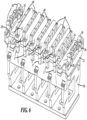
- the pallet rubbers 38 are shown in several possible positions fastened atop the knocker bars 16 (in Figs. 1 and 8 ) and/or atop standoff extensions 40 (in Figs. 5 and 9 ).
- the standoff extensions 40 comprise bars of a hard material that are removably supportable atop the standoffs 26.
- the extensions 40 are shaped to contact the mold when it is at least partially-supported by the knocker bars, effectively allowing transmission of vibration from the vibration frame 22 through the standoffs 26, and into the pallet 32.
- the hybrid vibration assembly 10 may be configured to agitate the mold 14 in several different modes. These different modes may comprise variations in how the pallet 32 and mold 14 are supported and/or attached to the vibration frame 22, and variations in how the contents of the mold 14 are agitated.
- the pallet rubbers 38 may be fastened atop the knocker bars 16 so that the pallet 32 rests on the rubbers 38.
- the assembly 10 may approximate the effect of earlier known vibration devices, such as the Besser Servopac ® .
- the assembly 10 is configured to impart vibratory motion to the mold 14 by coupling the frame/mold tie 30, moving the knocker bars 16 out of engagement with the pallet 32 (or by removing the knocker bars 16 from their mounting points 17), fastening standoff extensions 40 atop the vibration frame standoffs 26, fastening pallet rubbers 38 atop the vibration frame standoffs 26, and actuating the motors 12 to drive the vibrators 20 mounted to the vibrating frame 22.
- the pallet 32 is clamped against the mold box via the vibration frame pallet rubbers 38 and the frame/mold clamps 30 so that the pallet 32 cannot move relative to the mold box.
- the assembly 10 is configured to impart vibratory motion to the mold 14 by fastening the standoff extensions 40 (preferably lacking the pallet rubbers 38 of the second mode) to the vibration frame standoffs 26, decoupling the frame/mold clamps 30, installing knocker bars 16 and adjusting them to engage and support the mold 14, and actuating the motors 12 to cause the extensions 40 to vibrate with the vibration frame 22 and repeatedly strike the pallet 32 of the mold 14..
- the mold 14 is not attached to the vibration frame 22 via the frame/mold clamps 30, but the mobility of the mold 14 may still be limited to some degree by mold clamps or similar interfaces with a conventional concrete products machine known and typical in the art.
- vibration is intended to cover any rapid motion about and/or across an equilibrium position relative to one or more axes, and includes but is not limited to oscillatory motion, linear reciprocal motion, rotary reciprocal motion, and random motion.
Landscapes
- Engineering & Computer Science (AREA)
- Manufacturing & Machinery (AREA)
- Chemical & Material Sciences (AREA)
- Ceramic Engineering (AREA)
- Mechanical Engineering (AREA)
- Press-Shaping Or Shaping Using Conveyers (AREA)
- Moulds, Cores, Or Mandrels (AREA)
Claims (15)
- Hybride Vibrationsanordnung (10), umfassendeine Betonproduktform (14);einen Vibrationsrahmen (22), der positioniert ist, um Vibration an mindestens einen Abschnitt der Form (14) zu übertragen;einen stationären Rahmen (18), der den Vibrationsrahmen (22) trägt;Klopferstangen (16), die an dem stationären Rahmen (18) in Positionen getragen werden können, in denen sie, wenn sie installiert sind, mindestens einen Abschnitt der Form (14) tragen;einen Motor (12), der operativ mit einem Vibrator (20) verbunden ist, der an dem Vibrationsrahmen (22) montiert ist; undeine mechanische Rahmen/Form (14) -Klammer (30),dadurch gekennzeichnet, dass die mechanische Rahmen/Form (14) -Klammer (30) positioniert und betätigbar ist, um abwechselnd den Vibrationsrahmen (22) an die Form (14) zu koppeln und den Vibrationsrahmen (22) von der Form (14) zu entkoppeln.
- Hybride Vibrationsanordnung (10) nach Anspruch 1, in der die Form (14) einen Formkasten und eine Palette (32) umfasst, die konfiguriert ist, um einen offenen Boden des Formkastens entfernbar abzudecken.
- Hybride Vibrationsanordnung (10) nach Anspruch 2, in der die mechanische Rahmen/Form (14) -Klammer (30) den Vibrationsrahmen (22) an die Form (14) koppelt durch Koppeln des Vibrationsrahmens (22) an den Formkasten.
- Hybride Vibrationsanordnung (10) nach einem der Ansprüche 1 bis 3, in der der Vibrationsrahmen (22) Vibrationsrahmen (22) -Abstandshalter beinhaltet, die an eine obere Vibrationsrahmen (22) -Fläche montiert sind und optional positioniert sind, um mindestens einen Abschnitt der Form (14) zu tragen,
wobei optional die Klopferstangen (16) und die Vibrationsrahmen (22) -Abstandshalter horizontal verschachtelt sind, wenn die Klopferstangen (16) an dem stationären Rahmen (18) getragen werden. - Hybride Vibrationsanordnung (10) nach Anspruch 4, in der:die Klopferstangen (16) mindestens einen Abschnitt der Form (14) tragen;die Abstandshalter kürzer als die erweiterten Klopferstangen (16) sind; unddie Anordnung (10) Vibrationsrahmen (22) -Abstandshaltererweiterungen (40) beinhaltet, die entfernbar auf den Abstandshaltern getragen werden können und eine Form aufweisen, um die Form (14) zu berühren, wenn sie mindestens teilweise durch die Klopferstangen (16) getragen wird.
- Verfahren des Konfigurierens der Anordnung (10) nach Anspruch 3, um Vibrationsbewegung an eine Form (14) zu vermitteln durch:Koppeln der Rahmen/Form (14) -Klammer (30);Eingreifen der Klopferstangen (16) mit der Palette (32); undBetätigen des Motors (12), um den Form (14) -Vibrationsrahmen zum Vibrieren zu bringen.
- Verfahren nach Anspruch 6, in dem der Schritt des Eingreifens der Klopferstangen (16) mit der Palette (32) zusätzlich das Zulassen von limitierter relativer Bewegung zwischen der Palette (32) und dem Form (14) -Kasten während der Betätigung des Motors (12) umfasst.
- Verfahren nach Anspruch 6 oder 7, einschließlich des zusätzlichen Schritts des Befestigens von Palettengummis (38) an die Klopferstangen (16) in Positionen, die zulassen, dass die Palette (32) auf den Palettengummis (38) ruhen, wenn die Klopferstangen (16) die Palette (32) eingreifen.
- Verfahren des Konfigurierens der Anordnung (10) nach Anspruch 3, um Vibrationsbewegung an eine Form (14) zu vermitteln durch:Koppeln der Rahmen/Form (14) -Klammer (30);Halten der Klopferstangen (16) außerhalb eines Eingriffs mit der Palette (32);Konfigurieren des Vibrationsrahmens (22), um die Palette (32) gegen den Form (14) - Kasten zu halten; undBetätigen des Motors (12), um Bewegung an den Vibrationsrahmen (22) über den Vibrator (20) zu verteilen.
- Verfahren nach Anspruch 9, in dem der Schritt des Konfigurierens des Vibrationsrahmens (22) das Befestigen von Abstandshaltererweiterungen (40) an Abstandshalter (26) umfasst, die von einer Oberseite des Vibrationsrahmens (22) vorstehen, wobei die Erweiterungen positioniert sind, sodass die Palette (32) gegen den Form (14) -Kasten durch die Abstandshaltererweiterungen (40) gehalten wird, die wiederum durch die Abstandshalter (26) getragen werden, was die Bewegung der Palette (32) relativ zum Form (14) -Kasten einschränkt.
- Verfahren nach Anspruch 10, in dem der Schritt des Konfigurierens der Abstandshalter (26) ferner das Befestigen von Palettengummis (38) an den Abstandshaltererweiterungen (40) des Vibrationsrahmens (22) beinhaltet, sodass die Palette (32) gegen die Form (14) durch die Palettengummis (38) gehalten wird, die durch die Abstandshaltererweiterungen (40) getragen werden, die durch die Abstandshalter (26) getragen werden.
- Verfahren nach einem der Ansprüche 9 bis 11, in dem der Schritt des Haltens der Klopferstangen (16) außerhalb eines Eingriffs mit der Palette (32) das vollständige Entfernen der Klopferstangen (16) von dem Vibrationsrahmen (22) umfasst.
- Verfahren des Konfigurierens der Anordnung (10) nach Anspruch 2, um Vibrationsbewegung an eine Form (14) zu vermitteln durch:Befestigen von harten Abstandshaltererweiterungen (40) an dem Vibrationsrahmen (22);Entkoppeln der Rahmen/Form (14) -Klammer (30);Tragen der Form (14) auf den Abstandshaltererweiterungen (40); undBetätigen des Motors (12), um Bewegung an den Vibrationsrahmen (22) über den Vibrator (20) zu verteilen.
- Verfahren nach Anspruch 13, in dem der Schritt des Befestigens von harten Abstandshaltererweiterungen (40) an dem Vibrationsrahmen (22) das Befestigen der Abstandshaltererweiterungen (40) auf Abstandshaltern (26) des Vibrationsrahmens (22) umfasst, die von einer Oberseite des Vibrationsrahmens (22) vorstehen, sodass Vibration des Vibrationsrahmens (22) verursachen wird, dass die Abstandshaltererweiterungen (40) gegen die Form (14) schlagen, während sie mit dem Vibrationsrahmen (22) vibrieren,
wobei optional die Abstandshaltererweiterungen (40) die Palette (32) der Form (14) schlagen. - Verfahren nach Anspruch 13 oder 14, einschließlich des zusätzlichen Schritts des Installierens der Klopferstangen (16) in jeweilige Positionen, wo sie mit der Form (14) und/oder der Palette (32) in Eingriff kommen werden, vor dem Schritt des Betätigens des Motors (12).
Applications Claiming Priority (1)
| Application Number | Priority Date | Filing Date | Title |
|---|---|---|---|
| US17/966,763 US12325150B2 (en) | 2021-10-14 | 2022-10-14 | Hybrid mold vibration |
Publications (3)
| Publication Number | Publication Date |
|---|---|
| EP4353433A1 EP4353433A1 (de) | 2024-04-17 |
| EP4353433B1 true EP4353433B1 (de) | 2025-04-16 |
| EP4353433C0 EP4353433C0 (de) | 2025-04-16 |
Family
ID=84537125
Family Applications (1)
| Application Number | Title | Priority Date | Filing Date |
|---|---|---|---|
| EP22213854.7A Active EP4353433B1 (de) | 2022-10-14 | 2022-12-15 | Hybride formvibration |
Country Status (2)
| Country | Link |
|---|---|
| EP (1) | EP4353433B1 (de) |
| PL (1) | PL4353433T3 (de) |
Family Cites Families (2)
| Publication number | Priority date | Publication date | Assignee | Title |
|---|---|---|---|---|
| US4238177A (en) * | 1978-04-24 | 1980-12-09 | Crile Eugene E | Molding machine with vibration isolation |
| DE3709112C1 (de) * | 1986-08-27 | 1988-01-28 | Knauer Maschf Gmbh | Ruettelvorrichtung fuer eine Betonsteinformmaschine |
-
2022
- 2022-12-15 PL PL22213854.7T patent/PL4353433T3/pl unknown
- 2022-12-15 EP EP22213854.7A patent/EP4353433B1/de active Active
Also Published As
| Publication number | Publication date |
|---|---|
| EP4353433A1 (de) | 2024-04-17 |
| PL4353433T3 (pl) | 2025-06-16 |
| EP4353433C0 (de) | 2025-04-16 |
Similar Documents
| Publication | Publication Date | Title |
|---|---|---|
| US12325150B2 (en) | Hybrid mold vibration | |
| US6342750B1 (en) | Vibration drive for a mold | |
| US20250222621A1 (en) | Hybrid mold vibration | |
| DE69430443D1 (de) | Verfahren und vorrichtung zum herstellen von betongegenständen | |
| WO2006081480A3 (en) | Large pallet machine for forming molded products | |
| GB1349025A (en) | Vibratory 'creening machine | |
| WO2004074201A3 (en) | Form with displaceable vibratory panel | |
| US2531706A (en) | Vibrating device for a directed vibratory effect by means of rotatable vibratory members | |
| US6402499B1 (en) | Vibration drive | |
| EP4353433B1 (de) | Hybride formvibration | |
| US7309933B2 (en) | Vibrator for acting on an object in a predetermined direction and apparatus for producing concrete blocks | |
| GB2203682A (en) | Vibratory shakeout apparatus for use with castings | |
| KR200487980Y1 (ko) | 콘크리트제품 성형기용 동조진동장치 | |
| JPH05138298A (ja) | 消失模型鋳造用振動装置 | |
| JP3052281U (ja) | コンクリート型枠用加振装置 | |
| JPH079531U (ja) | 材料送り装置 | |
| US6758665B2 (en) | Concrete block vibrator | |
| JPH11226921A (ja) | コンクリートブロック成型機の振動装置 | |
| JPH10328783A (ja) | 鋳物砂の振動充填装置 | |
| JPH02233185A (ja) | 振動篩機 | |
| JP2549517B2 (ja) | コンクリ−ト型枠の加振方法及び加振装置 | |
| CN1307012C (zh) | 垂直圆周运动振动台 | |
| RU2036083C1 (ru) | Виброплощадка для формования железобетонных изделий | |
| CN219902557U (zh) | 混凝土模具振捣装置 | |
| JP3640389B2 (ja) | コンクリート二次製品の低騒音成形方法と装置 |
Legal Events
| Date | Code | Title | Description |
|---|---|---|---|
| PUAI | Public reference made under article 153(3) epc to a published international application that has entered the european phase |
Free format text: ORIGINAL CODE: 0009012 |
|
| STAA | Information on the status of an ep patent application or granted ep patent |
Free format text: STATUS: THE APPLICATION HAS BEEN PUBLISHED |
|
| AK | Designated contracting states |
Kind code of ref document: A1 Designated state(s): AL AT BE BG CH CY CZ DE DK EE ES FI FR GB GR HR HU IE IS IT LI LT LU LV MC ME MK MT NL NO PL PT RO RS SE SI SK SM TR |
|
| P01 | Opt-out of the competence of the unified patent court (upc) registered |
Effective date: 20240507 |
|
| STAA | Information on the status of an ep patent application or granted ep patent |
Free format text: STATUS: REQUEST FOR EXAMINATION WAS MADE |
|
| 17P | Request for examination filed |
Effective date: 20240902 |
|
| RBV | Designated contracting states (corrected) |
Designated state(s): AL AT BE BG CH CY CZ DE DK EE ES FI FR GB GR HR HU IE IS IT LI LT LU LV MC ME MK MT NL NO PL PT RO RS SE SI SK SM TR |
|
| GRAP | Despatch of communication of intention to grant a patent |
Free format text: ORIGINAL CODE: EPIDOSNIGR1 |
|
| STAA | Information on the status of an ep patent application or granted ep patent |
Free format text: STATUS: GRANT OF PATENT IS INTENDED |
|
| RIC1 | Information provided on ipc code assigned before grant |
Ipc: B28B 1/087 20060101AFI20241220BHEP |
|
| INTG | Intention to grant announced |
Effective date: 20250114 |
|
| GRAS | Grant fee paid |
Free format text: ORIGINAL CODE: EPIDOSNIGR3 |
|
| GRAA | (expected) grant |
Free format text: ORIGINAL CODE: 0009210 |
|
| STAA | Information on the status of an ep patent application or granted ep patent |
Free format text: STATUS: THE PATENT HAS BEEN GRANTED |
|
| AK | Designated contracting states |
Kind code of ref document: B1 Designated state(s): AL AT BE BG CH CY CZ DE DK EE ES FI FR GB GR HR HU IE IS IT LI LT LU LV MC ME MK MT NL NO PL PT RO RS SE SI SK SM TR |
|
| REG | Reference to a national code |
Ref country code: GB Ref legal event code: FG4D |
|
| REG | Reference to a national code |
Ref country code: CH Ref legal event code: EP Ref country code: DE Ref legal event code: R096 Ref document number: 602022013204 Country of ref document: DE |
|
| REG | Reference to a national code |
Ref country code: IE Ref legal event code: FG4D |
|
| U01 | Request for unitary effect filed |
Effective date: 20250417 |
|
| P04 | Withdrawal of opt-out of the competence of the unified patent court (upc) registered |
Free format text: CASE NUMBER: APP_19293/2025 Effective date: 20250423 |
|
| U07 | Unitary effect registered |
Designated state(s): AT BE BG DE DK EE FI FR IT LT LU LV MT NL PT RO SE SI Effective date: 20250424 |
|
| PG25 | Lapsed in a contracting state [announced via postgrant information from national office to epo] |
Ref country code: ES Free format text: LAPSE BECAUSE OF FAILURE TO SUBMIT A TRANSLATION OF THE DESCRIPTION OR TO PAY THE FEE WITHIN THE PRESCRIBED TIME-LIMIT Effective date: 20250416 |
|
| PG25 | Lapsed in a contracting state [announced via postgrant information from national office to epo] |
Ref country code: NO Free format text: LAPSE BECAUSE OF FAILURE TO SUBMIT A TRANSLATION OF THE DESCRIPTION OR TO PAY THE FEE WITHIN THE PRESCRIBED TIME-LIMIT Effective date: 20250716 Ref country code: GR Free format text: LAPSE BECAUSE OF FAILURE TO SUBMIT A TRANSLATION OF THE DESCRIPTION OR TO PAY THE FEE WITHIN THE PRESCRIBED TIME-LIMIT Effective date: 20250717 |
|
| PG25 | Lapsed in a contracting state [announced via postgrant information from national office to epo] |
Ref country code: HR Free format text: LAPSE BECAUSE OF FAILURE TO SUBMIT A TRANSLATION OF THE DESCRIPTION OR TO PAY THE FEE WITHIN THE PRESCRIBED TIME-LIMIT Effective date: 20250416 |
|
| PG25 | Lapsed in a contracting state [announced via postgrant information from national office to epo] |
Ref country code: RS Free format text: LAPSE BECAUSE OF FAILURE TO SUBMIT A TRANSLATION OF THE DESCRIPTION OR TO PAY THE FEE WITHIN THE PRESCRIBED TIME-LIMIT Effective date: 20250716 |
|
| PG25 | Lapsed in a contracting state [announced via postgrant information from national office to epo] |
Ref country code: IS Free format text: LAPSE BECAUSE OF FAILURE TO SUBMIT A TRANSLATION OF THE DESCRIPTION OR TO PAY THE FEE WITHIN THE PRESCRIBED TIME-LIMIT Effective date: 20250816 |
|
| U20 | Renewal fee for the european patent with unitary effect paid |
Year of fee payment: 4 Effective date: 20251118 |
|
| PG25 | Lapsed in a contracting state [announced via postgrant information from national office to epo] |
Ref country code: SM Free format text: LAPSE BECAUSE OF FAILURE TO SUBMIT A TRANSLATION OF THE DESCRIPTION OR TO PAY THE FEE WITHIN THE PRESCRIBED TIME-LIMIT Effective date: 20250416 |
|
| PGFP | Annual fee paid to national office [announced via postgrant information from national office to epo] |
Ref country code: TR Payment date: 20251210 Year of fee payment: 4 |
|
| PG25 | Lapsed in a contracting state [announced via postgrant information from national office to epo] |
Ref country code: CZ Free format text: LAPSE BECAUSE OF FAILURE TO SUBMIT A TRANSLATION OF THE DESCRIPTION OR TO PAY THE FEE WITHIN THE PRESCRIBED TIME-LIMIT Effective date: 20250416 |
|
| PGFP | Annual fee paid to national office [announced via postgrant information from national office to epo] |
Ref country code: IE Payment date: 20251126 Year of fee payment: 4 |
|
| PGFP | Annual fee paid to national office [announced via postgrant information from national office to epo] |
Ref country code: PL Payment date: 20251118 Year of fee payment: 4 |
|
| PG25 | Lapsed in a contracting state [announced via postgrant information from national office to epo] |
Ref country code: SK Free format text: LAPSE BECAUSE OF FAILURE TO SUBMIT A TRANSLATION OF THE DESCRIPTION OR TO PAY THE FEE WITHIN THE PRESCRIBED TIME-LIMIT Effective date: 20250416 |