US7309933B2 - Vibrator for acting on an object in a predetermined direction and apparatus for producing concrete blocks - Google Patents
Vibrator for acting on an object in a predetermined direction and apparatus for producing concrete blocks Download PDFInfo
- Publication number
- US7309933B2 US7309933B2 US11/056,541 US5654105A US7309933B2 US 7309933 B2 US7309933 B2 US 7309933B2 US 5654105 A US5654105 A US 5654105A US 7309933 B2 US7309933 B2 US 7309933B2
- Authority
- US
- United States
- Prior art keywords
- armature
- casing
- linear motor
- vibrator
- motor coils
- Prior art date
- Legal status (The legal status is an assumption and is not a legal conclusion. Google has not performed a legal analysis and makes no representation as to the accuracy of the status listed.)
- Expired - Fee Related, expires
Links
Images


Classifications
-
- B—PERFORMING OPERATIONS; TRANSPORTING
- B06—GENERATING OR TRANSMITTING MECHANICAL VIBRATIONS IN GENERAL
- B06B—METHODS OR APPARATUS FOR GENERATING OR TRANSMITTING MECHANICAL VIBRATIONS OF INFRASONIC, SONIC, OR ULTRASONIC FREQUENCY, e.g. FOR PERFORMING MECHANICAL WORK IN GENERAL
- B06B1/00—Methods or apparatus for generating mechanical vibrations of infrasonic, sonic, or ultrasonic frequency
- B06B1/02—Methods or apparatus for generating mechanical vibrations of infrasonic, sonic, or ultrasonic frequency making use of electrical energy
- B06B1/04—Methods or apparatus for generating mechanical vibrations of infrasonic, sonic, or ultrasonic frequency making use of electrical energy operating with electromagnetism
-
- B—PERFORMING OPERATIONS; TRANSPORTING
- B28—WORKING CEMENT, CLAY, OR STONE
- B28B—SHAPING CLAY OR OTHER CERAMIC COMPOSITIONS; SHAPING SLAG; SHAPING MIXTURES CONTAINING CEMENTITIOUS MATERIAL, e.g. PLASTER
- B28B1/00—Producing shaped prefabricated articles from the material
- B28B1/08—Producing shaped prefabricated articles from the material by vibrating or jolting
- B28B1/087—Producing shaped prefabricated articles from the material by vibrating or jolting by means acting on the mould ; Fixation thereof to the mould
-
- B—PERFORMING OPERATIONS; TRANSPORTING
- B28—WORKING CEMENT, CLAY, OR STONE
- B28B—SHAPING CLAY OR OTHER CERAMIC COMPOSITIONS; SHAPING SLAG; SHAPING MIXTURES CONTAINING CEMENTITIOUS MATERIAL, e.g. PLASTER
- B28B13/00—Feeding the unshaped material to moulds or apparatus for producing shaped articles; Discharging shaped articles from such moulds or apparatus
- B28B13/02—Feeding the unshaped material to moulds or apparatus for producing shaped articles
- B28B13/0215—Feeding the moulding material in measured quantities from a container or silo
- B28B13/023—Feeding the moulding material in measured quantities from a container or silo by using a feed box transferring the moulding material from a hopper to the moulding cavities
-
- B—PERFORMING OPERATIONS; TRANSPORTING
- B28—WORKING CEMENT, CLAY, OR STONE
- B28B—SHAPING CLAY OR OTHER CERAMIC COMPOSITIONS; SHAPING SLAG; SHAPING MIXTURES CONTAINING CEMENTITIOUS MATERIAL, e.g. PLASTER
- B28B3/00—Producing shaped articles from the material by using presses; Presses specially adapted therefor
- B28B3/02—Producing shaped articles from the material by using presses; Presses specially adapted therefor wherein a ram exerts pressure on the material in a moulding space; Ram heads of special form
- B28B3/022—Producing shaped articles from the material by using presses; Presses specially adapted therefor wherein a ram exerts pressure on the material in a moulding space; Ram heads of special form combined with vibrating or jolting
-
- B—PERFORMING OPERATIONS; TRANSPORTING
- B30—PRESSES
- B30B—PRESSES IN GENERAL
- B30B11/00—Presses specially adapted for forming shaped articles from material in particulate or plastic state, e.g. briquetting presses, tabletting presses
- B30B11/02—Presses specially adapted for forming shaped articles from material in particulate or plastic state, e.g. briquetting presses, tabletting presses using a ram exerting pressure on the material in a moulding space
- B30B11/022—Presses specially adapted for forming shaped articles from material in particulate or plastic state, e.g. briquetting presses, tabletting presses using a ram exerting pressure on the material in a moulding space whereby the material is subjected to vibrations
-
- H—ELECTRICITY
- H02—GENERATION; CONVERSION OR DISTRIBUTION OF ELECTRIC POWER
- H02K—DYNAMO-ELECTRIC MACHINES
- H02K16/00—Machines with more than one rotor or stator
-
- H—ELECTRICITY
- H02—GENERATION; CONVERSION OR DISTRIBUTION OF ELECTRIC POWER
- H02K—DYNAMO-ELECTRIC MACHINES
- H02K7/00—Arrangements for handling mechanical energy structurally associated with dynamo-electric machines, e.g. structural association with mechanical driving motors or auxiliary dynamo-electric machines
- H02K7/06—Means for converting reciprocating motion into rotary motion or vice versa
Definitions
- the invention relates to a vibrator for acting on an object in a predetermined direction and an apparatus for producing concrete blocks by acting on a mould in a vibratory manner.
- the vibrators used are imbalance exciters, which necessitate a complicated and a voluminous construction and are highly susceptible to wear at high vibration frequencies.
- linear motors A large number of designs of linear motors are known in which linear motor coils and an armature moved by the latter are provided but, as a rule, roller bearings are used for the armature, cf. U.S. Pat. No. 4,868,431.
- Such linear motors are designed for large strokes of the armature.
- mountings of this type only permit a movement of the armature in a predetermined direction, for high stroke frequencies at small strokes, such as are needed in the case of vibrators, roller mountings of this type are unsuitable since, because of the mass moment of inertia, the rollers then cannot follow the movement of the armature, so that the result is quickly correspondingly high wear because of the lack of lubrication.
- a vibrator comprising a casing and two identical, synchronously driven, electric linear motor coils arranged mirror-symmetrically therein is provided, between which coils there is an armature which can be moved to and fro in an oscillatory fashion by driving the linear motor coils appropriately in their longitudinal direction, the armature being mounted via wires arranged under spring bias in the casing.
- the armature can be moved at high frequency and with short strokes and both in the direction of the linear motor coils and in the direction perpendicular thereto, in order that, with a connection (for example with a force-transmitting and/or form-fitting engagement) to an object to be vibrated, that is to say moved in a direction other than the vibration direction, the armature can follow the said object, so that in this way no wear is caused.
- the result is a compact design little susceptible to wear.
- an apparatus for producing concrete blocks for constructional purposes comprising a mould having side walls and a vibration device for the mould for vibrating the mould horizontally, said vibration device comprising at least one pair of vibrators acting in a force-transmitting manner on opposite side walls of the mould.
- FIG. 1 shows an embodiment of a vibrator, halved, schematized and partly cut open.
- FIG. 2 shows a front view of the vibrator from FIG. 1 , halved and partly in section.
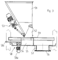
- FIG. 3 shows a filling device for a concrete block machine, schematically in side view.
- FIGS. 4 and 5 show a compaction station for a concrete block machine, schematically in front view and in plan view, respectively.
- FIGS. 1 and 2 The embodiment of a vibrator illustrated in FIGS. 1 and 2 comprises a substantially box-shaped casing 1 made of non-magnetic or non-magnetizable material such as an aluminium alloy and having side walls 2 , which are connected to one another by walls 3 to form an elongated box.
- a linear motor On the inner sides of the side walls 2 , arranged mirror-symmetrically in relation to each other as primary parts of a linear motor, there are linear motor coils 4 which can be driven and accordingly acted on electrically synchronously in the longitudinal direction of their arrangement via appropriate driving means 5 and electrical feed lines 6 , in order to cause an armature 7 arranged between the linear motor coils 4 as the secondary part of the linear motor to oscillate to and fro.
- the armature 7 comprises a carrier 8 made of a non-magnetic or non-magnetizable material such as an aluminium alloy which, on both sides, in each case has a permanent magnetic plate 9 which extends substantially over the area of the linear motor coils 4 , is fixed to the carrier 8 and can consist of a permanent magnet or can be assembled from a large number of permanent magnets.
- the carrier 8 is in each case provided with a fixing flange 10 at the ends.
- the armature 7 is held by a plurality of wires 11 (in particular made of spring steel wire), which extend through appropriate holes in the armature 7 and in the side walls 2 of the housing 1 and, on the outside of the side walls 2 , are clamped in clamping sleeves 12 with the interposition of disc spring packs 13 .
- wires 11 in particular made of spring steel wire
- This type of suspension is suitable in particular for small strokes of the armature 7 in the region of a few mm, in which mounting via antifriction elements is disadvantageous because of the lack of lubrication and, in addition, for relatively high frequencies of, for example, 30 to 50 Hz for the armature stroke.
- Mounting the armature 7 via antifriction elements in order to guide the armature 7 with respect to the linear motor coils 4 becomes expedient only when the strokes of the armature 7 reach at least approximately one antifriction element revolution.
- an operating spring 14 formed as a leaf spring extending in the direction of movement of the armature 7 is expediently fixed to the armature 7 on both sides and is formed in the shape of a bow which has a central limb 14 a and two limbs 14 b parallel thereto.
- the latter are fixed to the carrier 8 by means of screws 15 and, in addition, are clamped in by means of a clamping plate 16 on the carrier 8 adjacent to the curved connecting section 17 between the central limb 14 a and the respective limb 14 b , the clamping plate 16 being fixed to the fixing flange 10 by means of screws 18 .
- the limbs 14 b belong to the oscillating part, while the connecting section 17 and the central limb 14 a , which is fixed to the casing 1 by means of screws 19 and clamping plates 20 , form two sprung sections which are in each case stressed and unstressed appropriately as the armature 7 oscillates to and fro.
- the operating springs 14 are expediently matched in such a way that, in the mass/spring system which acts in the direction of movement of the armature, they continue to oscillate on their own when the desired stroke amplitude has been reached and virtually only the energy loss resulting from spring deformation has to be topped up but, on the other hand, not all of the acceleration energy has to be produced via the linear motor coils 4 .
- the stroke amplitude of the armature 7 is built up in that the linear motor coils 4 always apply sufficient energy that, during each stroke, in addition to tensioning the operating springs 14 , a small additional stroke of the armature 7 takes place until the desired stroke amplitude has been reached.
- Vibrators of the type described above can be used advantageously in a concrete block machine.
- the latter can have a filling device as illustrated in FIG. 3 .
- This comprises a hopper 51 with a funnel-like outlet and a flap 52 attached to the hopper 51 (or having a plurality of funnel-like outlets in each case closed by a flap), which can be moved between an open and a closed position by means of a drive 53 comprising a linkage acting on the flap 52 .
- a filling carriage 54 which is open at the top and the bottom and which can be moved over a table plate 55 between a position under the flap 52 and a position above a mould 57 located on a fabrication base 56 for concrete blocks, by means of a linear drive 58 , for example comprising an electric motor 58 a arranged on the filling carriage 54 and a pinion 58 b which is driven by the said electric motor 58 a and which engages in a rack 58 c that is parallel to the table plate 55 , or comprising a piston/cylinder drive or a crank drive.
- the filling carriage 54 is guided in this case by a horizontal guide 59 , preferably arranged on both sides of the filling carriage 54 .
- the fabrication base 56 is located above a vibratory table 60 which can be set oscillating vertically and which is mounted within a frame 61 on damping elements 62 , so that the vibrations originating from the vibratory table 60 are in practice not transmitted to the frame 61 and the foundations.
- the vibratory table 60 strikes the fabrication base 56 from below, preferably via impact bars 60 a , so that the said fabrication base 56 is moved up and down under the action of the force of gravity.
- a plunger 63 Arranged in the frame 61 is a plunger 63 which can be moved vertically and via which concrete mortar 64 in the mould 57 can be compacted.
- the plunger 63 can be moved by means of at least two synchronized motors 65 (four such motors 65 in the exemplary embodiment illustrated). This can be done via pinions 66 and racks 67 , as illustrated by way of example, which are connected to a top load 68 such that they can move in any direction, for example via a ball joint, and on the underside of which the plunger 63 is located.
- motors 65 for example a motor 65 which acts on the side of the mould 57 that is reached first by the filling carriage 54 during filling, while the two others are arranged adjacently, transversely with respect to the direction of travel, and act in the region of the side of the mould 57 reached last by the filling carriage 54 .
- the motors 65 can be electric or hydraulic motors. They are respectively coupled to a torque sensor 69 , which, in the case of an electric motor 65 , is expediently a current sensor and, in the case of a hydraulic motor 65 , is a pressure sensor.
- the torque sensors 69 are coupled to a control system 70 for the drive of the filling carriage 54 .
- the filling is changed by changing the speed of travel or the profile of the speed of travel of the filling carriage 54 during its forward and/or reverse travel and/or by changing its travel displacement (that is to say the extent to which the filling carriage 54 moves over the mould 57 or beyond the latter), in such a way that the result is always a substantially uniform filling and therefore a virtually constant product quality.
- At least two vibrators 71 act on the mould 57 in pairs in a force-transmitting manner, possibly even without the use of the vibratory table 60 , in order to carry out the compaction of the damp concrete mortar in the mould 57 by means of lateral vibration, for example at a frequency in the range from 30 to 50 Hz and with an amplitude of a few mm.
- eight vibrators 71 are distributed on the circumference of the mould 57 (here in each case two arranged diagonally in a respective corner region).
- the use of the vibrators 71 according to the invention not only permits good compaction but also rapid changing of the mould 57 , since, because they act in a force-transmitting manner, the vibrators 71 leave a clearance from the mould 57 in their neutral initial position or possibly also in their position pulled back from the mould 57 , so that the latter can readily be removed quickly and replaced in this state.
- the vibrators 71 can also be used as filling aids by being operated during the filling of the mould 57 .
- the vibrators 71 lead to the wall of the mould 57 striking the concrete mortar 64 put in, which means that the sides of the concrete blocks produced are improved.
- the filling is improved and made uniform.
Landscapes
- Engineering & Computer Science (AREA)
- Mechanical Engineering (AREA)
- Manufacturing & Machinery (AREA)
- Chemical & Material Sciences (AREA)
- Ceramic Engineering (AREA)
- Power Engineering (AREA)
- Physics & Mathematics (AREA)
- Electromagnetism (AREA)
- On-Site Construction Work That Accompanies The Preparation And Application Of Concrete (AREA)
- Apparatuses For Generation Of Mechanical Vibrations (AREA)
- Devices For Post-Treatments, Processing, Supply, Discharge, And Other Processes (AREA)
- Piezo-Electric Or Mechanical Vibrators, Or Delay Or Filter Circuits (AREA)
- Confectionery (AREA)
Abstract
The invention relates to a vibrator for acting on an object in a predetermined direction, comprising a casing and two identical, synchronously driven, electric linear motor coils arranged mirror-symmetrically therein, between which coils there is an armature which can be moved to and fro in an oscillatory fashion by driving the linear motor coils appropriately in their longitudinal direction, the armature being mounted via wires arranged under spring bias in the casing, and also to an apparatus for producing concrete blocks which uses vibrators of this type.
Description
The invention relates to a vibrator for acting on an object in a predetermined direction and an apparatus for producing concrete blocks by acting on a mould in a vibratory manner.
During the production of concrete blocks, it is known inter alia to make use of a mould which is vibrated by means of vibrators during and/or after being filled with damp concrete mortar, the vibrators acting on the side walls of the mould. In this case, the vibrators used are imbalance exciters, which necessitate a complicated and a voluminous construction and are highly susceptible to wear at high vibration frequencies.
A large number of designs of linear motors are known in which linear motor coils and an armature moved by the latter are provided but, as a rule, roller bearings are used for the armature, cf. U.S. Pat. No. 4,868,431. Such linear motors are designed for large strokes of the armature. Apart from the fact that mountings of this type only permit a movement of the armature in a predetermined direction, for high stroke frequencies at small strokes, such as are needed in the case of vibrators, roller mountings of this type are unsuitable since, because of the mass moment of inertia, the rollers then cannot follow the movement of the armature, so that the result is quickly correspondingly high wear because of the lack of lubrication.
The use of ball bearings, as they are described in the German Patent No. 953 890, or sliding bearings, as they are described in WO 91/17874, leads to corresponding problems.
It is an object of the invention to provide a vibrator for acting on an object in a predetermined direction, of which the design permits a movement of the armature in two mutually perpendicular directions.
It is a further object of the invention to provide a vibrator which permits operation at high stroke frequency with low wear.
It is still a further object of the invention to provide an apparatus for producing concrete blocks using a vibrational motion of a mould taking up a corresponding amount of mortar.
According to the present invention, a vibrator comprising a casing and two identical, synchronously driven, electric linear motor coils arranged mirror-symmetrically therein is provided, between which coils there is an armature which can be moved to and fro in an oscillatory fashion by driving the linear motor coils appropriately in their longitudinal direction, the armature being mounted via wires arranged under spring bias in the casing. Because of the free suspension, the armature can be moved at high frequency and with short strokes and both in the direction of the linear motor coils and in the direction perpendicular thereto, in order that, with a connection (for example with a force-transmitting and/or form-fitting engagement) to an object to be vibrated, that is to say moved in a direction other than the vibration direction, the armature can follow the said object, so that in this way no wear is caused. In general, the result is a compact design little susceptible to wear.
According to the invention, an apparatus for producing concrete blocks for constructional purposes is provided, said apparatus comprising a mould having side walls and a vibration device for the mould for vibrating the mould horizontally, said vibration device comprising at least one pair of vibrators acting in a force-transmitting manner on opposite side walls of the mould.
Further objects, advantages and embodiments of the invention can be gathered from the following description.
The invention will be explained in more detail below using exemplary embodiments illustrated in the appended drawings.
The embodiment of a vibrator illustrated in FIGS. 1 and 2 comprises a substantially box-shaped casing 1 made of non-magnetic or non-magnetizable material such as an aluminium alloy and having side walls 2, which are connected to one another by walls 3 to form an elongated box. On the inner sides of the side walls 2, arranged mirror-symmetrically in relation to each other as primary parts of a linear motor, there are linear motor coils 4 which can be driven and accordingly acted on electrically synchronously in the longitudinal direction of their arrangement via appropriate driving means 5 and electrical feed lines 6, in order to cause an armature 7 arranged between the linear motor coils 4 as the secondary part of the linear motor to oscillate to and fro.
The armature 7 comprises a carrier 8 made of a non-magnetic or non-magnetizable material such as an aluminium alloy which, on both sides, in each case has a permanent magnetic plate 9 which extends substantially over the area of the linear motor coils 4, is fixed to the carrier 8 and can consist of a permanent magnet or can be assembled from a large number of permanent magnets. In addition, on its opposite longitudinal sides, the carrier 8 is in each case provided with a fixing flange 10 at the ends.
Between the armature 7 and the linear motor coils 4 there is a narrow air gap of, for example, 0.5 mm. In order to maintain this, that is to say to keep the armature 7 centred between the linear motor coils 4 as the armature 7 oscillates to and fro, in the exemplary embodiment illustrated the armature 7 is held by a plurality of wires 11 (in particular made of spring steel wire), which extend through appropriate holes in the armature 7 and in the side walls 2 of the housing 1 and, on the outside of the side walls 2, are clamped in clamping sleeves 12 with the interposition of disc spring packs 13. This type of suspension is suitable in particular for small strokes of the armature 7 in the region of a few mm, in which mounting via antifriction elements is disadvantageous because of the lack of lubrication and, in addition, for relatively high frequencies of, for example, 30 to 50 Hz for the armature stroke. Mounting the armature 7 via antifriction elements in order to guide the armature 7 with respect to the linear motor coils 4 becomes expedient only when the strokes of the armature 7 reach at least approximately one antifriction element revolution.
Furthermore, in each case an operating spring 14 formed as a leaf spring extending in the direction of movement of the armature 7 is expediently fixed to the armature 7 on both sides and is formed in the shape of a bow which has a central limb 14 a and two limbs 14 b parallel thereto. The latter are fixed to the carrier 8 by means of screws 15 and, in addition, are clamped in by means of a clamping plate 16 on the carrier 8 adjacent to the curved connecting section 17 between the central limb 14 a and the respective limb 14 b, the clamping plate 16 being fixed to the fixing flange 10 by means of screws 18. As a result, the limbs 14 b belong to the oscillating part, while the connecting section 17 and the central limb 14 a, which is fixed to the casing 1 by means of screws 19 and clamping plates 20, form two sprung sections which are in each case stressed and unstressed appropriately as the armature 7 oscillates to and fro.
In this case, the operating springs 14 are expediently matched in such a way that, in the mass/spring system which acts in the direction of movement of the armature, they continue to oscillate on their own when the desired stroke amplitude has been reached and virtually only the energy loss resulting from spring deformation has to be topped up but, on the other hand, not all of the acceleration energy has to be produced via the linear motor coils 4.
In order to keep the expenditure on energy and therefore also the overall sizes of the components of the linear motors small, when the vibrator is switched on, the stroke amplitude of the armature 7 is built up in that the linear motor coils 4 always apply sufficient energy that, during each stroke, in addition to tensioning the operating springs 14, a small additional stroke of the armature 7 takes place until the desired stroke amplitude has been reached.
Vibrators of the type described above can be used advantageously in a concrete block machine.
The latter can have a filling device as illustrated in FIG. 3 . This comprises a hopper 51 with a funnel-like outlet and a flap 52 attached to the hopper 51 (or having a plurality of funnel-like outlets in each case closed by a flap), which can be moved between an open and a closed position by means of a drive 53 comprising a linkage acting on the flap 52. Underneath the hopper 51 there is a filling carriage 54 which is open at the top and the bottom and which can be moved over a table plate 55 between a position under the flap 52 and a position above a mould 57 located on a fabrication base 56 for concrete blocks, by means of a linear drive 58, for example comprising an electric motor 58 a arranged on the filling carriage 54 and a pinion 58 b which is driven by the said electric motor 58 a and which engages in a rack 58 c that is parallel to the table plate 55, or comprising a piston/cylinder drive or a crank drive. The filling carriage 54 is guided in this case by a horizontal guide 59, preferably arranged on both sides of the filling carriage 54.
The fabrication base 56 is located above a vibratory table 60 which can be set oscillating vertically and which is mounted within a frame 61 on damping elements 62, so that the vibrations originating from the vibratory table 60 are in practice not transmitted to the frame 61 and the foundations. During the vibrations, the vibratory table 60 strikes the fabrication base 56 from below, preferably via impact bars 60 a, so that the said fabrication base 56 is moved up and down under the action of the force of gravity.
Arranged in the frame 61 is a plunger 63 which can be moved vertically and via which concrete mortar 64 in the mould 57 can be compacted. The plunger 63 can be moved by means of at least two synchronized motors 65 (four such motors 65 in the exemplary embodiment illustrated). This can be done via pinions 66 and racks 67, as illustrated by way of example, which are connected to a top load 68 such that they can move in any direction, for example via a ball joint, and on the underside of which the plunger 63 is located.
Because the result is irregular filling, mainly in the direction of travel of the filling carriage 54, if only two motors 65 are used, these should expediently be arranged one after another in the direction of travel of the filling carriage 54. However, this also includes the fact that they can be offset in relation to the direction of travel, for example to act substantially on the diagonally opposite corners of the mould 57. In the case of four motors 65 corresponding to the exemplary embodiment illustrated, these are arranged one after another in pairs in the direction of travel of the filling carriage 54. However, it is also possible to use three motors 65, for example a motor 65 which acts on the side of the mould 57 that is reached first by the filling carriage 54 during filling, while the two others are arranged adjacently, transversely with respect to the direction of travel, and act in the region of the side of the mould 57 reached last by the filling carriage 54.
The motors 65 can be electric or hydraulic motors. They are respectively coupled to a torque sensor 69, which, in the case of an electric motor 65, is expediently a current sensor and, in the case of a hydraulic motor 65, is a pressure sensor. The torque sensors 69 are coupled to a control system 70 for the drive of the filling carriage 54. By this means, during production, depending on the difference between the measured values from the torque sensor 69 and a predetermined reference value representing the desired power consumption, which is generally identical for all the motors 65, the filling is changed by changing the speed of travel or the profile of the speed of travel of the filling carriage 54 during its forward and/or reverse travel and/or by changing its travel displacement (that is to say the extent to which the filling carriage 54 moves over the mould 57 or beyond the latter), in such a way that the result is always a substantially uniform filling and therefore a virtually constant product quality.
Accordingly, since measurements are carried out during each filling and compaction cycle, in the event of different torques (caused by different forces F1, F2, F3, F4 acting on the plunger 63, cf. FIG. 4 ), a correction to the concrete block height can be made immediately.
As FIG. 5 illustrates, at least two vibrators 71 according to the invention act on the mould 57 in pairs in a force-transmitting manner, possibly even without the use of the vibratory table 60, in order to carry out the compaction of the damp concrete mortar in the mould 57 by means of lateral vibration, for example at a frequency in the range from 30 to 50 Hz and with an amplitude of a few mm. In the exemplary embodiment illustrated, eight vibrators 71 are distributed on the circumference of the mould 57 (here in each case two arranged diagonally in a respective corner region).
The use of the vibrators 71 according to the invention not only permits good compaction but also rapid changing of the mould 57, since, because they act in a force-transmitting manner, the vibrators 71 leave a clearance from the mould 57 in their neutral initial position or possibly also in their position pulled back from the mould 57, so that the latter can readily be removed quickly and replaced in this state.
Furthermore, in the case of compaction by means of vibration through the vibratory table and/or the vibrators 71, equalisation of the elasticity of the mechanical equipment, but also of the concrete blocks to be formed, takes place, in that the drive, by means of that motor 65 which is assigned the greater power or the greater torque, runs synchronously with the other motor or motors 65. This avoids the situation in which the top-load side of the plunger 63 sinks in the poorer filled region as compared with the well-filled region. The synchronization of the motors 65 is carried out electronically, for example via an appropriate displacement measurement.
The vibrators 71 can also be used as filling aids by being operated during the filling of the mould 57. In this case, operated as horizontal vibrators, the vibrators 71 lead to the wall of the mould 57 striking the concrete mortar 64 put in, which means that the sides of the concrete blocks produced are improved. At the same time, by controlling the force exerted by the vibrators 71, their vibration amplitude and frequency, the filling is improved and made uniform.
While the invention has been shwon and described with reference to preferred embodiments, it should be apparent to one of ordinary skill in the art that many changes and modifications may be made without departing from the spirit and scope of the invention as defined in the claims.
Claims (6)
1. A vibrator for acting on an object in a predetermined direction, comprising:
a casing;
two identical, synchronously driven, electric linear motor coils arranged mirror-symmetrically in the casing;
wherein between the coils there is an armature moveable to and from in an oscillatory fashion by corresponding driving the linear motor coils in the longitudinal direction of the motor coils; and
wherein the armature is mounted via wires arranged under spring bias in the casing;
wherein the armature is biased in both stroke directions by means of at least one operating spring; and
wherein the at least one operating spring is formed in the manner of a bow and is arranged in the direction of movement of the armature, its free limb substantially parallel to a central limb being fixed to the armature and the central limb being fixed to the casing.
2. The vibrator according to claim 1 , wherein the wires hold the armature centered between the linear motor coils.
3. The vibrator according to claim 1 , wherein the wires are clamped in clamping sleeves at the ends with the interposition of disc springs.
4. The vibrator according to claim 1 , wherein the at least one operating spring is coordinated in such a way that, in the mass/spring system which acts in the direction of movement of the armature, it continues to oscillate on its own when the desired stroke amplitude has been reached and virtually only the energy loss resulting from spring deformation has to be topped up.
5. The vibrator according to claim 1 , wherein the armature comprises a carrier and two identical permanent magnetic plates which are fixed to both sides of the carrier.
6. The vibrator according to claim 1 , for acting on a wall of a mould for compacting a granular material, in particular a damp concrete mortar.
Applications Claiming Priority (2)
| Application Number | Priority Date | Filing Date | Title |
|---|---|---|---|
| DE102004009251.6 | 2004-02-26 | ||
| DE102004009251A DE102004009251B4 (en) | 2004-02-26 | 2004-02-26 | Vibrator for applying an object in a predetermined direction and apparatus for producing concrete blocks |
Publications (2)
| Publication Number | Publication Date |
|---|---|
| US20050189823A1 US20050189823A1 (en) | 2005-09-01 |
| US7309933B2 true US7309933B2 (en) | 2007-12-18 |
Family
ID=34745277
Family Applications (1)
| Application Number | Title | Priority Date | Filing Date |
|---|---|---|---|
| US11/056,541 Expired - Fee Related US7309933B2 (en) | 2004-02-26 | 2005-02-11 | Vibrator for acting on an object in a predetermined direction and apparatus for producing concrete blocks |
Country Status (4)
| Country | Link |
|---|---|
| US (1) | US7309933B2 (en) |
| EP (1) | EP1568419B1 (en) |
| AT (1) | ATE361789T1 (en) |
| DE (2) | DE102004009251B4 (en) |
Families Citing this family (13)
| Publication number | Priority date | Publication date | Assignee | Title |
|---|---|---|---|---|
| US8167431B2 (en) * | 2005-12-21 | 2012-05-01 | International Business Machines Corporation | Universal stereographic trigger peripheral for electronic equipment |
| US8172399B2 (en) * | 2005-12-21 | 2012-05-08 | International Business Machines Corporation | Lumen optimized stereo projector using a plurality of polarizing filters |
| US8152303B2 (en) * | 2005-12-21 | 2012-04-10 | International Business Machines Corporation | Signal synthesizer for periodic acceleration and deceleration of rotating optical devices |
| US8182099B2 (en) | 2005-12-21 | 2012-05-22 | International Business Machines Corporation | Noise immune optical encoder for high ambient light projection imaging systems |
| US8157381B2 (en) * | 2005-12-21 | 2012-04-17 | International Business Machines Corporation | Method to synchronize stereographic hardware to sequential color rendering apparatus |
| US8189038B2 (en) * | 2005-12-21 | 2012-05-29 | International Business Machines Corporation | Stereographic projection apparatus with passive eyewear utilizing a continuously variable polarizing element |
| US8162482B2 (en) | 2006-08-30 | 2012-04-24 | International Business Machines Corporation | Dynamic projector refresh rate adjustment via PWM control |
| DE102008011272A1 (en) * | 2008-02-26 | 2009-08-27 | Institut für Fertigteiltechnik und Fertigbau Weimar e.V. | Concrete paver with harmonic vibration due to shape excitation |
| US9430921B2 (en) | 2014-09-24 | 2016-08-30 | Taction Technology Inc. | Systems and methods for generating damped electromagnetically actuated planar motion for audio-frequency vibrations |
| US10573139B2 (en) | 2015-09-16 | 2020-02-25 | Taction Technology, Inc. | Tactile transducer with digital signal processing for improved fidelity |
| CN105479593A (en) * | 2016-01-25 | 2016-04-13 | 广西辰宇建材科技有限公司 | Full-automatic building block casting machine |
| CN114658225B (en) * | 2022-04-01 | 2023-11-10 | 中和华丰建设集团有限公司 | Concrete construction equipment and construction method |
| CN115847591B (en) * | 2022-12-06 | 2023-09-01 | 福建群峰机械有限公司 | Brick making machine of high accuracy brickmaking |
Citations (19)
| Publication number | Priority date | Publication date | Assignee | Title |
|---|---|---|---|---|
| DE819161C (en) | 1949-10-28 | 1951-10-31 | Elektro Mechanik G M B H | Vibration device |
| GB664941A (en) | 1949-04-16 | 1952-01-16 | Lockers Engineers Ltd | Improvements in and relating to a vibratory motor |
| DE953890C (en) | 1955-10-28 | 1956-12-06 | Voigt & Haeffner Ag | Oscillating armature motor, the armature of which has longitudinal ball bearings on two opposite sides for parallel guidance |
| US3173664A (en) | 1963-07-01 | 1965-03-16 | Isaacson | Vibrator |
| DE2621181A1 (en) | 1975-05-13 | 1976-11-25 | Lohjan Kalkkitehdas Oy Lojo Ka | CASTING MACHINE FOR THE PASTING OF CONCRETE ELEMENTS |
| US4868431A (en) | 1987-03-05 | 1989-09-19 | Shinko Electric Co., Ltd. | Linear motor with an elongated core using oppositely polarized magnets to maximize perpendicular flux lines |
| FR2715424A1 (en) | 1994-01-21 | 1995-07-28 | Quille Entreprise | Control for forming concrete walls in long row |
| DE69021087T2 (en) | 1989-03-10 | 1995-11-30 | Skako A/S, Faaborg | METHOD AND DEVICE FOR PRODUCING COMPONENTS FROM VIBRATED CONCRETE. |
| US5682132A (en) * | 1994-09-28 | 1997-10-28 | Seiko Instruments Inc. | Vibrating module |
| US5936516A (en) | 1997-01-31 | 1999-08-10 | Motorola, Inc. | Vibrating apparatus and method therefor |
| US5959939A (en) | 1995-06-28 | 1999-09-28 | Unaco Systems Ab | Electrodynamic driving means for acoustic emitters |
| DE19921145A1 (en) | 1999-05-07 | 2000-11-09 | Kobra Formen & Anlagenbau Gmbh | Vibration drive for a form |
| EP1116524A1 (en) | 1999-07-27 | 2001-07-18 | Iwasaki Seiki Corporation | Electromagnetic device and driver circuit |
| US6289662B1 (en) * | 1999-02-05 | 2001-09-18 | Zinser Textilmaschinen Gmbh | Method of and apparatus for clamping the underwinding thread of a spinning spindle |
| DE10026985A1 (en) | 2000-05-31 | 2001-12-06 | Elek Sche Automatisierungs Und | Linear synchronous motor has new type of secondary part in which carbon-reinforced plastic is used, and permanent magnets are machined directly into secondary part |
| EP1187509A1 (en) | 2000-09-04 | 2002-03-13 | Sambu Communics Co., Ltd. | Signal converter functioning as a loudspeaker or a receiver and as a vibrator |
| DE10129468A1 (en) | 2000-11-11 | 2002-06-27 | Gedib Ingbuero Innovation | Compaction device for molded body uses vibrating table coupled to spring-mass system with forced excitation |
| US7078833B2 (en) * | 2002-05-31 | 2006-07-18 | Minebea Co., Ltd. | Force motor with increased proportional stroke |
| US7078832B2 (en) * | 2002-10-16 | 2006-07-18 | Matsushita Refrigeration Company | Linear motor, and linear compressor using the same |
-
2004
- 2004-02-26 DE DE102004009251A patent/DE102004009251B4/en not_active Expired - Fee Related
-
2005
- 2005-02-11 US US11/056,541 patent/US7309933B2/en not_active Expired - Fee Related
- 2005-02-22 AT AT05003733T patent/ATE361789T1/en not_active IP Right Cessation
- 2005-02-22 DE DE502005000673T patent/DE502005000673D1/en not_active Expired - Lifetime
- 2005-02-22 EP EP05003733A patent/EP1568419B1/en not_active Expired - Lifetime
Patent Citations (19)
| Publication number | Priority date | Publication date | Assignee | Title |
|---|---|---|---|---|
| GB664941A (en) | 1949-04-16 | 1952-01-16 | Lockers Engineers Ltd | Improvements in and relating to a vibratory motor |
| DE819161C (en) | 1949-10-28 | 1951-10-31 | Elektro Mechanik G M B H | Vibration device |
| DE953890C (en) | 1955-10-28 | 1956-12-06 | Voigt & Haeffner Ag | Oscillating armature motor, the armature of which has longitudinal ball bearings on two opposite sides for parallel guidance |
| US3173664A (en) | 1963-07-01 | 1965-03-16 | Isaacson | Vibrator |
| DE2621181A1 (en) | 1975-05-13 | 1976-11-25 | Lohjan Kalkkitehdas Oy Lojo Ka | CASTING MACHINE FOR THE PASTING OF CONCRETE ELEMENTS |
| US4868431A (en) | 1987-03-05 | 1989-09-19 | Shinko Electric Co., Ltd. | Linear motor with an elongated core using oppositely polarized magnets to maximize perpendicular flux lines |
| DE69021087T2 (en) | 1989-03-10 | 1995-11-30 | Skako A/S, Faaborg | METHOD AND DEVICE FOR PRODUCING COMPONENTS FROM VIBRATED CONCRETE. |
| FR2715424A1 (en) | 1994-01-21 | 1995-07-28 | Quille Entreprise | Control for forming concrete walls in long row |
| US5682132A (en) * | 1994-09-28 | 1997-10-28 | Seiko Instruments Inc. | Vibrating module |
| US5959939A (en) | 1995-06-28 | 1999-09-28 | Unaco Systems Ab | Electrodynamic driving means for acoustic emitters |
| US5936516A (en) | 1997-01-31 | 1999-08-10 | Motorola, Inc. | Vibrating apparatus and method therefor |
| US6289662B1 (en) * | 1999-02-05 | 2001-09-18 | Zinser Textilmaschinen Gmbh | Method of and apparatus for clamping the underwinding thread of a spinning spindle |
| DE19921145A1 (en) | 1999-05-07 | 2000-11-09 | Kobra Formen & Anlagenbau Gmbh | Vibration drive for a form |
| EP1116524A1 (en) | 1999-07-27 | 2001-07-18 | Iwasaki Seiki Corporation | Electromagnetic device and driver circuit |
| DE10026985A1 (en) | 2000-05-31 | 2001-12-06 | Elek Sche Automatisierungs Und | Linear synchronous motor has new type of secondary part in which carbon-reinforced plastic is used, and permanent magnets are machined directly into secondary part |
| EP1187509A1 (en) | 2000-09-04 | 2002-03-13 | Sambu Communics Co., Ltd. | Signal converter functioning as a loudspeaker or a receiver and as a vibrator |
| DE10129468A1 (en) | 2000-11-11 | 2002-06-27 | Gedib Ingbuero Innovation | Compaction device for molded body uses vibrating table coupled to spring-mass system with forced excitation |
| US7078833B2 (en) * | 2002-05-31 | 2006-07-18 | Minebea Co., Ltd. | Force motor with increased proportional stroke |
| US7078832B2 (en) * | 2002-10-16 | 2006-07-18 | Matsushita Refrigeration Company | Linear motor, and linear compressor using the same |
Non-Patent Citations (1)
| Title |
|---|
| Syed A. Nasar, et al., Linear Electric Motors: Theory, Design, and Practical Applications, Linear Motion Oscillators, Chapter 8, pp. 233-243, 1987 (Publication date). |
Also Published As
| Publication number | Publication date |
|---|---|
| EP1568419B1 (en) | 2007-05-09 |
| DE102004009251B4 (en) | 2006-05-24 |
| EP1568419A1 (en) | 2005-08-31 |
| ATE361789T1 (en) | 2007-06-15 |
| DE102004009251A1 (en) | 2005-09-22 |
| DE502005000673D1 (en) | 2007-06-21 |
| US20050189823A1 (en) | 2005-09-01 |
Similar Documents
| Publication | Publication Date | Title |
|---|---|---|
| US7309933B2 (en) | Vibrator for acting on an object in a predetermined direction and apparatus for producing concrete blocks | |
| US6342750B1 (en) | Vibration drive for a mold | |
| CN1193866C (en) | Compacting device and method for compacting molded bodies of granular materials | |
| GB1349025A (en) | Vibratory 'creening machine | |
| CA2316455C (en) | Vibrator drive | |
| KR102351706B1 (en) | Concrete block forming device | |
| US12325150B2 (en) | Hybrid mold vibration | |
| US20250222621A1 (en) | Hybrid mold vibration | |
| JP3077043B2 (en) | Vibration device for vanishing model casting | |
| KR200487980Y1 (en) | Tuned vibrator for concrete products forming machine | |
| US3331112A (en) | Machine for molding concrete blocks | |
| CN213632876U (en) | Vibrating compaction forming device | |
| CN211099976U (en) | Centrifugal force vibration platform | |
| CN201082562Y (en) | Percussive vibration table device | |
| JPH0740107U (en) | Vibration equipment for compaction in concrete product molding equipment | |
| CN215410904U (en) | Suspension device for vibration exciter | |
| US20050189668A1 (en) | Method and apparatus for producing concrete blocks | |
| CN1307012C (en) | Vertical circular motion vibration bench | |
| EP1170103A2 (en) | Unit for vibrating concrete and similar materials, and concrete product production plant incorporating the said unit | |
| EP4353433B1 (en) | Hybrid mold vibration | |
| EP1318001A2 (en) | Vibrating device for use in a concrete block molding machine | |
| JP2002144308A (en) | Concrete casting equipment | |
| HK1037574A (en) | Apparatus for generating vibrations | |
| RU2712460C1 (en) | Device for vibration compaction of cathode-heating units filling | |
| SU1735000A1 (en) | Vibration platform for compacting concrete mixes |
Legal Events
| Date | Code | Title | Description |
|---|---|---|---|
| AS | Assignment |
Owner name: HESS MASCHINENFABRIK GMBH & CO. KG, GERMANY Free format text: ASSIGNMENT OF ASSIGNORS INTEREST;ASSIGNOR:BACKS, ULRICH;REEL/FRAME:015969/0582 Effective date: 20050331 |
|
| FEPP | Fee payment procedure |
Free format text: PAYOR NUMBER ASSIGNED (ORIGINAL EVENT CODE: ASPN); ENTITY STATUS OF PATENT OWNER: SMALL ENTITY |
|
| REMI | Maintenance fee reminder mailed | ||
| LAPS | Lapse for failure to pay maintenance fees | ||
| STCH | Information on status: patent discontinuation |
Free format text: PATENT EXPIRED DUE TO NONPAYMENT OF MAINTENANCE FEES UNDER 37 CFR 1.362 |
|
| FP | Lapsed due to failure to pay maintenance fee |
Effective date: 20111218 |