EP4353376A1 - Méthode de fabrication d'un bras mécanique - Google Patents
Méthode de fabrication d'un bras mécanique Download PDFInfo
- Publication number
- EP4353376A1 EP4353376A1 EP23201711.1A EP23201711A EP4353376A1 EP 4353376 A1 EP4353376 A1 EP 4353376A1 EP 23201711 A EP23201711 A EP 23201711A EP 4353376 A1 EP4353376 A1 EP 4353376A1
- Authority
- EP
- European Patent Office
- Prior art keywords
- matrix
- holes
- initial
- sheet metal
- hole
- Prior art date
- Legal status (The legal status is an assumption and is not a legal conclusion. Google has not performed a legal analysis and makes no representation as to the accuracy of the status listed.)
- Pending
Links
- 238000004519 manufacturing process Methods 0.000 title claims abstract description 51
- 239000011159 matrix material Substances 0.000 claims abstract description 68
- 239000002184 metal Substances 0.000 claims abstract description 63
- 238000000034 method Methods 0.000 claims abstract description 41
- 238000000465 moulding Methods 0.000 claims abstract description 21
- 230000008569 process Effects 0.000 claims abstract description 17
- 238000005452 bending Methods 0.000 claims description 30
- 238000012545 processing Methods 0.000 claims description 27
- 230000000149 penetrating effect Effects 0.000 claims description 5
- 238000003801 milling Methods 0.000 claims description 4
- 239000005557 antagonist Substances 0.000 claims description 2
- 238000005520 cutting process Methods 0.000 abstract description 9
- 230000008901 benefit Effects 0.000 abstract description 8
- 230000007246 mechanism Effects 0.000 abstract description 7
- 239000011265 semifinished product Substances 0.000 abstract description 6
- 238000012546 transfer Methods 0.000 abstract description 2
- 238000007688 edging Methods 0.000 description 47
- 238000003754 machining Methods 0.000 description 13
- 239000000463 material Substances 0.000 description 9
- 230000008878 coupling Effects 0.000 description 7
- 238000010168 coupling process Methods 0.000 description 7
- 238000005859 coupling reaction Methods 0.000 description 7
- 238000003825 pressing Methods 0.000 description 6
- 238000004512 die casting Methods 0.000 description 3
- 239000000047 product Substances 0.000 description 3
- 230000009471 action Effects 0.000 description 2
- 230000000694 effects Effects 0.000 description 2
- 230000003466 anti-cipated effect Effects 0.000 description 1
- 230000015572 biosynthetic process Effects 0.000 description 1
- 238000010276 construction Methods 0.000 description 1
- 230000002950 deficient Effects 0.000 description 1
- 238000013461 design Methods 0.000 description 1
- 238000011161 development Methods 0.000 description 1
- 230000018109 developmental process Effects 0.000 description 1
- 238000005553 drilling Methods 0.000 description 1
- 238000000605 extraction Methods 0.000 description 1
- 230000003116 impacting effect Effects 0.000 description 1
- 230000006872 improvement Effects 0.000 description 1
- 230000035515 penetration Effects 0.000 description 1
- 238000002360 preparation method Methods 0.000 description 1
- 230000004044 response Effects 0.000 description 1
- 238000004513 sizing Methods 0.000 description 1
- 239000011343 solid material Substances 0.000 description 1
- 239000007858 starting material Substances 0.000 description 1
- 239000000725 suspension Substances 0.000 description 1
- 238000009966 trimming Methods 0.000 description 1
Images


Classifications
-
- B—PERFORMING OPERATIONS; TRANSPORTING
- B21—MECHANICAL METAL-WORKING WITHOUT ESSENTIALLY REMOVING MATERIAL; PUNCHING METAL
- B21D—WORKING OR PROCESSING OF SHEET METAL OR METAL TUBES, RODS OR PROFILES WITHOUT ESSENTIALLY REMOVING MATERIAL; PUNCHING METAL
- B21D53/00—Making other particular articles
- B21D53/88—Making other particular articles other parts for vehicles, e.g. cowlings, mudguards
-
- B—PERFORMING OPERATIONS; TRANSPORTING
- B21—MECHANICAL METAL-WORKING WITHOUT ESSENTIALLY REMOVING MATERIAL; PUNCHING METAL
- B21D—WORKING OR PROCESSING OF SHEET METAL OR METAL TUBES, RODS OR PROFILES WITHOUT ESSENTIALLY REMOVING MATERIAL; PUNCHING METAL
- B21D19/00—Flanging or other edge treatment, e.g. of tubes
- B21D19/08—Flanging or other edge treatment, e.g. of tubes by single or successive action of pressing tools, e.g. vice jaws
- B21D19/088—Flanging or other edge treatment, e.g. of tubes by single or successive action of pressing tools, e.g. vice jaws for flanging holes
-
- B—PERFORMING OPERATIONS; TRANSPORTING
- B21—MECHANICAL METAL-WORKING WITHOUT ESSENTIALLY REMOVING MATERIAL; PUNCHING METAL
- B21D—WORKING OR PROCESSING OF SHEET METAL OR METAL TUBES, RODS OR PROFILES WITHOUT ESSENTIALLY REMOVING MATERIAL; PUNCHING METAL
- B21D28/00—Shaping by press-cutting; Perforating
- B21D28/24—Perforating, i.e. punching holes
- B21D28/26—Perforating, i.e. punching holes in sheets or flat parts
-
- B—PERFORMING OPERATIONS; TRANSPORTING
- B21—MECHANICAL METAL-WORKING WITHOUT ESSENTIALLY REMOVING MATERIAL; PUNCHING METAL
- B21D—WORKING OR PROCESSING OF SHEET METAL OR METAL TUBES, RODS OR PROFILES WITHOUT ESSENTIALLY REMOVING MATERIAL; PUNCHING METAL
- B21D5/00—Bending sheet metal along straight lines, e.g. to form simple curves
-
- B—PERFORMING OPERATIONS; TRANSPORTING
- B21—MECHANICAL METAL-WORKING WITHOUT ESSENTIALLY REMOVING MATERIAL; PUNCHING METAL
- B21D—WORKING OR PROCESSING OF SHEET METAL OR METAL TUBES, RODS OR PROFILES WITHOUT ESSENTIALLY REMOVING MATERIAL; PUNCHING METAL
- B21D53/00—Making other particular articles
- B21D53/84—Making other particular articles other parts for engines, e.g. connecting-rods
-
- B—PERFORMING OPERATIONS; TRANSPORTING
- B60—VEHICLES IN GENERAL
- B60G—VEHICLE SUSPENSION ARRANGEMENTS
- B60G7/00—Pivoted suspension arms; Accessories thereof
- B60G7/001—Suspension arms, e.g. constructional features
-
- F—MECHANICAL ENGINEERING; LIGHTING; HEATING; WEAPONS; BLASTING
- F16—ENGINEERING ELEMENTS AND UNITS; GENERAL MEASURES FOR PRODUCING AND MAINTAINING EFFECTIVE FUNCTIONING OF MACHINES OR INSTALLATIONS; THERMAL INSULATION IN GENERAL
- F16C—SHAFTS; FLEXIBLE SHAFTS; ELEMENTS OR CRANKSHAFT MECHANISMS; ROTARY BODIES OTHER THAN GEARING ELEMENTS; BEARINGS
- F16C7/00—Connecting-rods or like links pivoted at both ends; Construction of connecting-rod heads
- F16C7/08—Connecting-rods or like links pivoted at both ends; Construction of connecting-rod heads made from sheet metal
-
- B—PERFORMING OPERATIONS; TRANSPORTING
- B21—MECHANICAL METAL-WORKING WITHOUT ESSENTIALLY REMOVING MATERIAL; PUNCHING METAL
- B21D—WORKING OR PROCESSING OF SHEET METAL OR METAL TUBES, RODS OR PROFILES WITHOUT ESSENTIALLY REMOVING MATERIAL; PUNCHING METAL
- B21D41/00—Application of procedures in order to alter the diameter of tube ends
- B21D41/02—Enlarging
- B21D41/026—Enlarging by means of mandrels
Definitions
- the field of application of the present invention concerns the use of production processes based on sheet metal molding for the production of some mechanical elements.
- the invention indicates a production method applicable for the creation of certain types of pieces which are typically produced with other techniques, different from sheet metal molding, as these are pieces whose characteristics do not lend themselves poorly to production by cutting. and sheet metal bending (i.e., the operations that are normally performed in molding processes, which use a series of molds in sequence).
- a mechanical "arm” is an elongated mechanical element which has, typically in correspondence with the two heads, some holes, designed to couple this "arm” to other elements of a more complex mechanism.
- the "arms” are always connected to other elements, through mobile couplings.
- the holes made at the ends of these "arms” are used to implement these mobile connections, and are normally designed to couple with pins, which must be inserted into these holes.
- Such "hole-pin” coupling typically offer a degree of freedom in rotation; in other words, these pins must rotate on their axis inside the hole, and between the pin and the hole there must not normally be enough tolerance to allow significant vibrations of the pin inside the hole.
- the present invention aims to indicate a new sheet metal molding procedure that allows the production of mechanical "arms", i.e., elongated elements provided with holes at their ends and suitable to act as a mechanical connection between other elements of more complex mechanisms.
- the present invention while accepting the use of more complex molds than those normally used, aims to indicate a new production method that can be applied for the production of a number of mechanical "arms", even when their shape requires a greater thickness than that obtainable from cutting a single sheet of sheet metal and, above all, when requirements of mechanical resistance and precision of the holes are required, such that the known technique is still oriented towards production methods other than sequences of cuts, folding, drawing, i.e. processes of sheet metal molding.
- a preparatory purpose for achieving the objectives of the invention is also to indicate a particular type of bending mold that allows holes to be made at the ends of the "arms" with excellent control of the machining precision.
- the main advantage of the present invention consists in the fact that the production method implemented according to the teachings of the present invention allows to offer a satisfactory response to the main needs for which it was conceived, i.e., the need to extend production by sheet metal molding (which is a very efficient production processes) even to quite common mechanical elements, such as mechanical "arms", which normally, and according to known practice, are often produced with die-casting processes.
- Figure 1a shows an initial piece of flat sheet metal, indicated with the number 110.
- Said initial piece of flat sheet metal 110 is already shaped, in the sense that it has already been subjected to some initial cutting processes that can be easily carried out with various techniques, including, for example, through the use of appropriate cutting molds.
- these initial processes we will not describe these initial processes since, as mentioned, they are relatively simple and, above all, they can be carried out according to the known technique, therefore they do not present particular technical problems. So, just the essential characteristics of said initial flat sheet metal piece 110 are described which allow the processing to continue according to the teachings of the present invention.
- the first characteristic to be highlighted is that said initial piece of flat sheet metal 110 has an elongated shape and a longitudinal axis of symmetry, which is indicated in Figure 1a with the number 101.
- said initial piece of flat sheet metal 110 has one or more pairs of initial holes.
- Each pair of said initial holes is also arranged symmetrically with respect to said longitudinal symmetry axis 101; one of these two pairs of initial holes is indicated in Figure 1a with the numbers 111 and 112.
- Figure 1b shows said initial piece of flat sheet metal 110 after the execution of two 90-degree bends along said two bending lines 102.
- said initial piece of flat sheet metal 110 is transformed into a intermediate folded semi-finished piece, indicated in Figure 1b with the number 120.
- Said intermediate folded semi-finished piece 120 has some peculiar characteristics which distinguish the production method according to the present invention.
- a first characteristic consists in the fact that said intermediate folded semi-finished piece 120 has two parallel flaps of sheet metal, indicated with the numbers 121 and 122, and these two flaps are spaced apart so as to form a space between them of constant width: width which, in Figure 1b , is indicated with the number 123.
- a further characteristic of said intermediate folded semi-finished piece 120 consists in the fact that, due to the symmetries of said initial piece of flat sheet metal 110, and the bends performed, the holes of each pair are substantially aligned one in front of the other and spaced apart from each other approximately how far apart the two parallel folding lines 102 are, i.e., at the distance 123.
- FIG 1b there is shown the hole 111, which is located in the flap 121 of said folded intermediate semi-finished piece 120, behind it, only partially visible in Figure 1b (because covered by the flap 121), there is the hole 112 which is located in the flap 122, and which is aligned with the corresponding hole 111.
- Said intermediate folded semi-finished piece 120 begins to make apparent the main characteristics of a mechanical "arm”.
- the folding lines 102 must not necessarily be understood as folding lines in the strict sense.
- the bending edges it is not necessary for the bending edges to be sharp edges (as in the schematic and indicative representation proposed in Figure 1b ), indeed, it could even be more convenient to make gentle bends, avoiding stressing the material of the sheet metal.
- the flaps 121 and 122, once folded, in the areas where said initial holes are present are parallel, so that the holes are aligned and as coaxial as possible.
- the two holes 111 and 112 (as well as the holes of any other pairs of holes that are present in the "arm") will hardly be perfectly coaxial.
- the overall hole constituted by the pair of holes aligned on the two flaps 121 and 122 does not have a continuous and smooth internal surface, as it should be to ensure a good sliding coupling with another mechanical element which has a pin designed to be inserted into the holes of the "arm", to rotate easily inside the hole itself.
- the process with which it is possible to obtain the desired finish in the holes of a mechanical "arm", made with a sheet metal molding production process consists in the so-called edging of both holes which, after bending the initial piece of flat sheet metal 110, are aligned one in front of the other. This edging of the pair of holes is carried out with a further 90-degree bend towards the inside.
- hole edging operation is an operation that requires forcefully deforming the material of which the sheet metal is made by subjecting it to considerable traction. These operations are the most difficult to control precisely because they involve very high forces and are sensitive even to small imperfections in the starting material.
- the present invention proposes the use of an original edging mold, conceived and designed to create edgings with bending in the opposite direction acting on holes which, at the end, will result to be perfectly coaxial.
- Figure 2a shows, in a schematic and essential way, a mold that allows the required edgings to be made with excellent control of the machining precision with regards to the internal finish of the hole which must appear on the mechanical "arm" once it is finished.
- the mold presented in Figure 2a is indicated as a whole with the number 200.
- the matrix of the edging mold 200 according to the invention is indicated in Figure 2a with the number 220, and has some differences compared to the typical matrixes used in hole edging molds.
- the latter are usually designed to be positioned above the pressing basement and support the semi-finished product, or in any case they are positioned in a firm way to oppose the movement of a single punch, which, in the act of pressing, goes to compress forcefully onto the matrix.
- the matrix 220 according to the teachings of the present invention, however, is designed to be inserted inside the so-called folded intermediate semi-finished piece 120, and more precisely in the space that forms between the two flaps 121 and 122 as a result of the folds.
- the thickness of said matrix 220 is indicated with the number 123, precisely to highlight that said matrix 220 is designed to fit precisely between the two flaps 121 and 122 of the folded intermediate semi-finished piece 120.
- said matrix 220 is mounted in the pressing compartment vertically, and fixed to the base, while the intermediate folded semi-finished piece 120 is placed above so that the two flaps 121 and 122 adhere to the lateral surfaces of the matrix itself.
- said matrix 220 has at least one passing-through matrix-hole, indicated in Figure 2a with the number 225, and that said matrix-hole 225 aligns with a pair of initial holes 111 and 112 present in the folded intermediate semi-finished piece 120.
- an essential characteristic of said matrix 220 is that it is designed for the execution of the edgings of both initial holes found in the two flaps 121 and 122 of the folded intermediate semi-finished piece 120.
- the axis of said matrix-hole 225 is indicated in Figure 2a with the number 224 and, as mentioned, the matrix 220 is designed so that said axis 224 overlaps with the axes of the initial holes 111 and 112. Therefore, the two initial holes 111 and 112 and the matrix hole 225, before the edging operation, are all aligned, with the alignment precision that can be obtained, which typically cannot be a high precision, given that this operation will have to be performed repetitively and as quickly as possible.
- matrix-hole 225 must be slightly larger than the initial holes 111 and 112, because the latter must be edged, and therefore the edged bending operation ends up widening them, folding their edge onto the internal surface of the matrix-hole 225.
- the edging mold 200 shown in Figure 2a then highlights the presence of two punches, indicated with the numbers 211 and 212.
- Said punches 211 and 212 also share the same axis 224 of the matrix 220 and they are designed to move in the opposite direction, one towards the other, along said axis 224, as shown by the dotted arrows shown in Figure 2a , which highlight precisely the movement of the two punches.
- Said two punches 211 and 212 therefore, are designed to fit into the matrix hole 225, penetrating from the two opposite sides, thus performing the two edgings of the initial holes 111 and 112 present on the two flaps 121 and 122 of said folded intermediate semi-finished piece 120.
- the axis 224 shared by the two punches 211 and 212 and the matrix 220, instead, can be positioned and determined with much more controllable precision, given that the processes that concern the manufacture of the molds, as well as their fixing in the pressing compartment, are carried out once and for all, and can be carried out with great precision as the speed of preparation of the molds is not critical.
- a second technical advantage that can be obtained with this machining procedure concerns the internal face of the holes after their edging.
- the edging maneuver stresses the material in such a way as to make it difficult to control the exact size of the cutting edge of the sheet metal inside the hole, it is also true that this edge extends towards the inside of the hole (impacting only the length of the folded part) in an area where precision is not required, given that the hole of the "arm" must be sized accurately only in the final dimension of the hole after the edgings, and this dimension is determined by the size of the punches which are tools that can be produced with an excellent control of the precision.
- the hole that, in the end, is obtained on the "arm" therefore, presents excellent requirements for controllability of the machining precision, given that it is composed of the two holes on the two flaps 121 and 122 of the folded intermediate semi-finished piece 120, which can be made perfectly aligned from the edging maneuver. Furthermore, the internal surface of the overall hole on the "arm” is also workable with excellent precision, since it is not determined by the effect of a cut of a sheet metal but by a conformation determined by a punch, the size of which is excellently controllable.
- FIG. 2b a further feature of the mold 200 is shown, and in particular a feature that concerns the matrix 220.
- said matrix 220 is composed of two parts that can be separated from each other, and which in Figure 2b are indicated with the numbers 221 and 222.
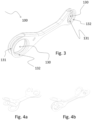
- Figure 3 shows an example of a mechanical "arm", indicated as a whole with the number 100. It is an "arm” for a suspension, which has been actually produced by applying the teachings of the invention, and which allows us to illustrate some variants implementation or other construction details that are compatible with the method taught.
- the "arm” 100 represented in Figure 3 recalls the classic shape of mechanical "arms” made by die-casting, but allows us to appreciate very clearly how it was instead obtained by molding starting from a piece of sheet metal.
- Said holes 130 constitute the most critical parts of the "arm" 100 to be made, because they typically have to be made with precision machining.
- both holes 130 is indicated with the number 132, and although it is composed of the folds made on the initial holes undergone to edging of the sheet metal, said internal surface 132 offers optimal contact with the external surface of an eventual pin, which can be inserted into each of the two holes 130, and which can rotate inside the hole itself by sliding on said surface 132.
- the surfaces 132 although not continuous, offer a good support surface also suitable for being lubricated.
- Said surfaces 132 are not continuous, but they are still an excellent approximation of the internal surfaces of a hole obtained by milling. Their non-continuity is due to the presence of a central crack, visible on both holes, and indicated with the number 131.
- Said crack 131 corresponds to the two margins of the initial holes, before they are undergone to edging: it is observed that any cutting inaccuracies (for making the initial holes), as well as the inaccuracies determined by the edging maneuver, are reflected exclusively on the width of this crack, i.e., in an aspect on which there is no precision constraint, given that the crack 131 may not even be regular. What matters, as already mentioned, is that each hole 130 has a very precise diameter to guarantee exactly the desired tolerances in the coupling with the pin which will then have to be inserted into that hole 130.
- the precision of the diameter of the hole 130 is guaranteed by the edging maneuver, i.e., by the precision with which the punches and the matrix, belonging to the particular edging mold that has been used, are made.
- the machining precision of the final hole 130 can be further improved by providing a further processing phase in which milling or filing is carried out of the internal surface 132 of the final hole 130.
- the two punches which carry out the edging on each side, can take on a shape which is not perfectly cylindrical, but slightly beveled at their tip, i.e., the part which is first inserted into the matrix-hole 225 (as well as, obviously, in the initial hole 111 or 112, of which each punch must carry out the edging) and then assume a constant circular section in the central part of the punch.
- the edging can be carried out by acting with a gradual impact on the edge of the two holes to be undergone to edging, so as not to produce too violent impacts (and dents) on the material of which the sheet metal is made, in particular in the area where this material must form the internal surfaces 132 of the hole 130.
- the alternating action of the two punches can take place by repeating the penetration action of the punches two or more times, so as to make the processing of the internal surface 132 of the holes 130 increasingly precise, avoiding the formation of imperfections in corresponding to the crack, imperfections which could protrude towards the internal part of the hole 130.
- the production method may include some additional folds that allow you to work with greater flexibility in the shape to be given to the finished "arm" 100.
- Figures 4a and 4b show a sequence of folds different from the essential one shown with the help of Figures 1a and 1b , which were intended to show only the effects of the essential folds along the directions parallel to the longitudinal symmetry axis 101 of the initial piece of flat sheet metal 110.
- Figure 4a shows the execution of two (additional) folds along transversal directions with respect to the longitudinal axis of symmetry.
- the piece, folded as shown in Figure 4a is then folded with the two additional 90-degree folds so as to obtain the folded intermediate semi-finished piece in which the initial holes are approximately aligned in front of each other.
- This second folding maneuver is shown in Figure 4b and (contrary to the folds shown in Figure 4a which represent an optional choice) constitutes an essential fold for the application of the method according to the invention.
- the example of making an "arm” shows some technical advantages of the invention, which is characterized by the way in which the edgings of the holes are made.
- the first folds shown in Figure 4a influence the difficulty of performing the second folds, shown in Figure 4b , given that the latter are no longer performed along a straight line, but rather along a line that has an angle.
- the bends shown in Figure 4b therefore stress the material of which the sheet metal is made in tension, expanding it quite a bit to form the desired bend.
- This maneuver is one of those that, once again, can compromise the perfect alignment of the holes, which must be achieved after the folds shown in Figure 4b .
- This risk of imperfection is completely acceptable, given that the production method of the "arm” then proceeds with the edging maneuvers previously described, which ensure that the machining requirements foreseen for the holes 130 of the finished "arm” are obtained.
- the edging carried out according to the teachings of the invention is very effective, because it allows the invention to be implemented according to many variations: for example, by performing non-essential folds, for the sole purpose of playing with the final shape to be given to the "arm", and without being limited by the potential difficulty of completing the manufacturing of the "arm” respecting the tolerances foreseen in the machining of the holes 130.
- the edging mold 200 which represents an essential tool for the implementation of the method according to the invention, can be made according to different variants.
- various arrangements can be adopted for the shape of the punches, in order to stress more or less gradually the material of which the sheet metal is made, in the act of the edging.
- Some variations may concern the material with which the punches 211 and 212 are made, this because their contact with the sheet metal during the edging of the holes 130, determines the surface processing characteristics of the holes 130, and in particular their internal surfaces 132 which, as stated several times, must be the part of the "arm" most cared for from the point of view of surface processing.
- the matrix 220 can be made according to some variations, for example it can be composed of a number of separable pieces greater than two, given that the only requirement that matters is that the hole in the matrix 225 can be opened to allow the extraction of the matrix which would otherwise be trapped on the hole 130 after its edging.
- an area of improvement can therefore concern the presence of further accessory elements, or precautions that can be introduced precisely to integrate tools for manipulating the artefact, or to facilitate its manipulation during all production phases.
- Another interesting variation that may concern the matrix 220 is about its overall shape. In fact, in the present description, attention has always been paid on the hole 225, without saying anything about the external conformation of this matrix 220.
- it can also be designed to also act as a matrix for the bending mold, to perform the two 90 degree bends parallel to the longitudinal axis 101 of the initial flat sheet metal piece 110.
- the external border of the matrix 220 is suitably designed for the purpose.
- This choice i.e., the choice of integrating the edging matrix (previously described), in a bending mold has the non-negligible advantage that this tool, after bending, would already be positioned between the two flaps 121 and 122 of the intermediate folded semi-finished piece 120, as it appears after the folding operation.
- This double functionality does not create any problem of mutual interference between the two functions because they impact the conformation of two different areas of the tool which must act as a matrix both in the bending mold and in the edging mold. All you need is the foresight to make the hole 225, or holes, of the matrix in the correct position, i.e., taking into account of the positioning that the tool must have to carry out the initial bending operation.
- the initial flat sheet metal piece 110 would be positioned above the matrix 220 which also acts as an opposing tool (i.e., as a matrix) of a bending mold, this being suitably shaped in its upper part.
- the intermediate folded semi-finished piece 120 would already be ready to undergo the edging of the initial holes 111 and 112, which would be aligned with the hole, or holes, 225 of the matrix 220 that does not need to be moved after the execution of the folding; a series of relatively onerous manipulations would thus be saved.
- the invention is therefore susceptible to further evolutionary efforts, which can be carried out on multiple fronts: such eventual developments, if not included in this description, may be the subject of further patent applications associated with the present invention.
Applications Claiming Priority (1)
| Application Number | Priority Date | Filing Date | Title |
|---|---|---|---|
| IT202200021129 | 2022-10-13 |
Publications (1)
| Publication Number | Publication Date |
|---|---|
| EP4353376A1 true EP4353376A1 (fr) | 2024-04-17 |
Family
ID=84830049
Family Applications (1)
| Application Number | Title | Priority Date | Filing Date |
|---|---|---|---|
| EP23201711.1A Pending EP4353376A1 (fr) | 2022-10-13 | 2023-10-04 | Méthode de fabrication d'un bras mécanique |
Country Status (1)
| Country | Link |
|---|---|
| EP (1) | EP4353376A1 (fr) |
Citations (6)
| Publication number | Priority date | Publication date | Assignee | Title |
|---|---|---|---|---|
| DE102008015393A1 (de) * | 2008-03-20 | 2009-09-24 | Thyssenkrupp Umformtechnik Gmbh | Verfahren zum Herstellen eines Lenkers aus Blech |
| JP4431488B2 (ja) * | 2004-12-17 | 2010-03-17 | 中西金属工業株式会社 | ロッカーアームの製造方法 |
| KR101416548B1 (ko) * | 2013-11-07 | 2014-07-09 | 주식회사 동양테크 | 버링 구조를 가지는 리어 어퍼 암 제조방법 |
| US20190061453A1 (en) * | 2017-08-30 | 2019-02-28 | Ford Global Technologies, Llc | Vehicle control arm for a wheel suspension |
| CN112705618A (zh) * | 2020-12-29 | 2021-04-27 | 宁波建新底盘系统有限公司 | 一种细长类汽车底盘系统零件加工工装 |
| EP3957411A1 (fr) * | 2019-04-15 | 2022-02-23 | Nippon Steel Corporation | Procédé et dispositif de fabrication de composant de liaison |
-
2023
- 2023-10-04 EP EP23201711.1A patent/EP4353376A1/fr active Pending
Patent Citations (6)
| Publication number | Priority date | Publication date | Assignee | Title |
|---|---|---|---|---|
| JP4431488B2 (ja) * | 2004-12-17 | 2010-03-17 | 中西金属工業株式会社 | ロッカーアームの製造方法 |
| DE102008015393A1 (de) * | 2008-03-20 | 2009-09-24 | Thyssenkrupp Umformtechnik Gmbh | Verfahren zum Herstellen eines Lenkers aus Blech |
| KR101416548B1 (ko) * | 2013-11-07 | 2014-07-09 | 주식회사 동양테크 | 버링 구조를 가지는 리어 어퍼 암 제조방법 |
| US20190061453A1 (en) * | 2017-08-30 | 2019-02-28 | Ford Global Technologies, Llc | Vehicle control arm for a wheel suspension |
| EP3957411A1 (fr) * | 2019-04-15 | 2022-02-23 | Nippon Steel Corporation | Procédé et dispositif de fabrication de composant de liaison |
| CN112705618A (zh) * | 2020-12-29 | 2021-04-27 | 宁波建新底盘系统有限公司 | 一种细长类汽车底盘系统零件加工工装 |
Similar Documents
| Publication | Publication Date | Title |
|---|---|---|
| DE112015005146T5 (de) | Laminierter Eisenkern und Verfahren zum Herstellen desselben | |
| EP0700738A1 (fr) | Procédé de fabrication d'une aube creuse de turbomachine | |
| EP4353376A1 (fr) | Méthode de fabrication d'un bras mécanique | |
| US3680381A (en) | Method of and apparatus for forming parts with re-entrant surfaces | |
| US4117793A (en) | Pole claw member for a dynamo electric machine rotor | |
| US3314137A (en) | Making product articles by combined cavitation and machining of bar stock | |
| US2723445A (en) | Method of making a hollow turbine blade | |
| US2105099A (en) | Method of manufacturing keys | |
| JP4872827B2 (ja) | 異形フランジ付き棒状鍛造品の製造方法 | |
| SE416116B (sv) | Sett att framstella skerlenkar for sagkedjor | |
| JPS63154216A (ja) | 長フランジ製品の製造方法 | |
| CN107249776B (zh) | 用于预制金属部件的高温锻造的方法以及适用于锻造的成形设备 | |
| JP4559579B2 (ja) | プレス装置の押しズレ防止構造 | |
| JP3962156B2 (ja) | クリップ成形方法及びクリップ成形装置 | |
| JPH04123821A (ja) | 板材のだれ、段差防止剪断加工方法 | |
| Mukhirmesh et al. | The procedure of experimental work and finite element simulation to produce spline shape multi-stage deep-drawing operation | |
| RU2347638C2 (ru) | Способ изготовления полуфабриката для элемента в форме крыла | |
| FR2818565A1 (fr) | Procede de fabrication de pieces moulees puis forgees comprenant un ou deux evidements et installation de mise en oeuvre | |
| JP5342525B2 (ja) | ヨークシャフト製造方法 | |
| KR20160145934A (ko) | 차량의 프레임 구성용 체결 하우징의 제조방법 | |
| JP3982147B2 (ja) | 中空ラック軸の成形方法 | |
| US1332726A (en) | Sheet-metal pliers | |
| JPH06179035A (ja) | クランク軸の製造法 | |
| US4559804A (en) | Method and apparatus for forging wedge-shaped parts | |
| TWI721454B (zh) | 複合式沖裁裝置及其方法 |
Legal Events
| Date | Code | Title | Description |
|---|---|---|---|
| PUAI | Public reference made under article 153(3) epc to a published international application that has entered the european phase |
Free format text: ORIGINAL CODE: 0009012 |
|
| STAA | Information on the status of an ep patent application or granted ep patent |
Free format text: STATUS: THE APPLICATION HAS BEEN PUBLISHED |
|
| AK | Designated contracting states |
Kind code of ref document: A1 Designated state(s): AL AT BE BG CH CY CZ DE DK EE ES FI FR GB GR HR HU IE IS IT LI LT LU LV MC ME MK MT NL NO PL PT RO RS SE SI SK SM TR |