BACKGROUND OF THE INVENTION
FIELD OF THE INVENTION
-
This invention relates to an electric sauna oven comprising a stone chamber, a first set of heating elements, a second set of heating elements and a control unit.
DESCRIPTION OF PRIOR ART
-
In relation to sauna ovens, and especially electric sauna ovens, heating of the sauna space is typically arranged using a relatively simple heater structure. In a typical electric sauna oven structure, all heating elements are located inside an open stone chamber in a more or less uniform manner and controlled simultaneously, so that the space heating takes place primarily via heating of stones or other ceramic elements placed in the stone chamber to surround the heating elements. In such an arrangement, the intensity of space heating is therefore tightly related to the temperature of the stones placed in the stone chamber, so that control over the temperature of the stones without greatly influencing the temperature of the space being heated, or vice versa, is not possible.
-
Due to this shortcoming, a typical sauna oven arrangement does not offer an optimal sauna experience to the user. That is, with the temperature of the sauna space being tied to the temperature of the stones, it often becomes impossible to reach the desired temperature of the space without overly heating up the stones. This, in turn, may result in overly aggressive steaming of water tossed over the stones, said water tossing being part of the standard use practice of a Finnish-type sauna. On the other hand, also the opposite situation is possible, wherein the stones of the sauna oven cannot be brought to the desired temperature without overly heating up the sauna space. This is often the case, for example, when the stones have cooled down as a result of excessive amounts of water being tossed on them.
-
Another problem associated with the described sauna oven arrangement is the suboptimal use of energy, specifically electric power. That is, the necessity to overly heat either the stones arranged in the stone chamber or the sauna space itself in order to obtain the desired heat conditions, inevitably leads to higher levels of energy use than would be the case with optimized heating conditions.
SUMMARY OF THE INVENTION
-
An object of the present invention is to solve the above-mentioned drawbacks and to provide an electric sauna oven for more precise control over the temperature of the sauna space and the stones or other ceramic elements placed in the stone chamber. This object is achieved with an electric sauna oven according to independent claim 1.
-
By utilizing an electric sauna oven having a first set of heating elements, a second set of heating elements and a control unit adapted to control a first and a second switch independently of each other to adjust heating of the first and the second set of heating elements, it is possible to obtain an electric sauna oven for an improved user experience, while also avoiding unnecessary heating of the sauna space.
-
Preferred embodiments of the invention are disclosed in the dependent claims.
BRIEF DESCRIPTION OF DRAWINGS
-
In the following the present invention will be described in closer detail by way of example and with reference to the attached drawings, in which
- Figure 1 illustrates an electric sauna oven as seen from above,
- Figure 2 illustrates a cross-cut section the electric sauna oven of Figure 1 along the line A - A,
- Figure 3 illustrates a second embodiment of the electric sauna oven, and
- Figure 4 illustrates a third embodiment of the electric sauna oven.
DESCRIPTION OF AT LEAST ONE EMBODIMENT
-
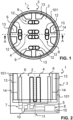
Figure 1 illustrates schematically an electric sauna oven 1 according to one embodiment of the invention, as seen from above. The illustration of Figure 1 serves only to showcase the key structural elements of the electric sauna oven, and therefore the exact dimensions or positioning of the structural elements presented in the figure do not necessarily correspond to the actual construction. Also, the illustration of Figure 1 does not correspond to the ready-to-use -state of the electric sauna oven, as a plurality of stones or some other form of ceramic component typically provided in the sauna oven before use are not illustrated to better demonstrate the structure.
-
As seen in the example of Figure 1, the electric sauna oven 1 comprises a stone chamber 2, the stone chamber 2 being open to the outside of the electric sauna oven 1 and limited by a housing 3. More precisely, the stone chamber 2 of said example is formed as a cylinder having a middle axis 11 extending in vertical direction, wherein the housing 3 limits the stone chamber 2 in a radial direction of the middle axis 11. In other words, the stone chamber 2 is in said example arranged to be open upwards in the vertical direction at the top part of the electric sauna oven 1, so that the inside of the stone chamber is exposed to the surrounding space. The housing 3 also extends to cover the bottom part of the stone chamber 2 opposite the open top part. In other embodiments of the electric sauna oven, however, the shape of the housing 3, and thereby also the shape of the stone chamber 2, may deviate from said example. For example, the housing 3 may be formed to have an elliptical or rectangular cross section, rather than circular as illustrated in Figure 1. The stone chamber 2 may also be arranged such that only part of it is made available for the stones or other ceramic elements.
-
Figure 2 illustrates schematically a cross-cut section the electric sauna oven of Figure 1. The cross-cut section follows the line A - A illustrated in Figure 1, corresponding to a vertical middle plane of the electric sauna oven. Similarly to Figure 1, the illustration of Figure 2 serves only to showcase the key structural elements of the electric sauna oven, without the purpose of accurately illustrating the dimensions or positioning of the structural elements presented in the figure. Furthermore, some non-crucial or technically less relevant components that may be included in the actual construction, have been left out of the figure to better illustrate the key structural elements. Some structural elements embedded within the housing have been illustrated with a dashed line.
-
As best seen in the example of Figure 2, the electric sauna oven 1 further comprises a first set of heating elements 4 extending in the vertical direction in the stone chamber 2 and connected to a first switch 5. More precisely, in said example heating elements 12 comprised in the first set of heating elements 4 extend in the stone chamber 2 through the housing 3 at the bottom part of the stone chamber, such that the heating elements 12 extend to at least a part of the height of the stone chamber. The first set of heating elements 4 connects to the first switch 5 that is arranged in the electric sauna oven 1 outside the stone chamber 2, for example in a space provided below the stone chamber, such that the first set of heating elements 4 and the first switch 5 are formed as parts of a same electric circuit. In the example of Figures 1 and 2, the heating elements 12 are formed as resistors comprising several vertically adjoined rod sections, but their shape may deviate from said example in other embodiments of the electric sauna oven.
-
Similarly, the electric sauna oven 1 also comprises a second set of heating elements 6 extending in vertical direction in the stone chamber 2 and connected to a second switch 7. In other words, the second set of heating elements 6 and the second switch 7 according to the examples of Figures 1 and 2 form a similar arrangement to the first set of heating elements 4 and the first switch 5, wherein the first set of heating elements 4 is arranged closer to the middle section of the stone chamber 2 than the second set of heating elements 6. The electric sauna oven 1 further comprises a control unit 8 adapted to control the first 5 and the second switch 7 independently of each other to adjust heating of the first 4 and the second set of heating elements 6. In other words, the control unit 8 is adapted to control the first 5 and the second switch 7 independently in order to allow or disallow electric current to pass through the vertically adjoined rod sections comprised in the heating elements of the first 4 and the second set of heating elements 6.
-
In the example of Figures 1 and 2, the electric sauna oven 1 further comprises a third set of heating elements 9 extending in vertical direction in the stone chamber 2 and connected to a third switch 10. In other words, the third set of heating elements 9 together with the third switch 10 according to the examples of Figures 1 and 2 form a similar arrangement to the first set of heating elements 4 together with the first 5 switch or the second set of heating elements 6 together with the second switch 7, wherein the third set of heating elements 9 is arranged further from the middle section of the stone chamber 2 than the first set of heating elements 4. More precisely, in said example the second 6 and the third set of heating elements 9 are arranged to an equal distance from the middle section of the stone chamber 2, to form a symmetrical pattern around the middle axis 11. The control unit 8 is arranged to control the third switch 10 independently of the first 5 and the second switch 7 to adjust heating of the third set of heating elements 9, in other words so as to allow or disallow electric current to pass through the vertically adjoined rod sections comprised in the heating elements of the third set of heating elements 9.
-
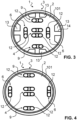
Figure 3 illustrates a second embodiment of the electric sauna oven 1, which deviates from the example of Figures 1 and 2 in that the cross section of the housing 3 has been arranged in an elliptical shape. Also, in said example, the third set of heating elements 9 has been arranged further from the middle section of the stone chamber 2 than the second set of heating elements 6, as opposed to the previous example in which they are arranged to an equal distance from the middle section of the stone chamber 2.
-
In the example of Figures 1 and 2, each of the first 4, the second 6 and the third set of heating elements 9 comprises two heating elements 12. In the case of the second 6 and the third set of heating elements 9, said two heating elements are arranged to opposite sides of the stone chamber 2, so that in the symmetrical pattern formed by the heating elements around the middle axis 11, each heating element is neighboring on two sides a heating element belonging to a different group of heating elements. In said example, the two heating elements 12 comprised in the first set of heating elements 4 are arranged to different sides of a vertical middle plane defined by the middle axis 11 in the middle section of the stone chamber 2 parallel to each other. However, the number of heating elements 12 comprised in each set of heating elements, being preferably at least two, as well as their exact positioning, may be arranged differently in other embodiments of the electric sauna oven 1. Also, the third set of heating elements 9 may be entirely excluded in some embodiments of the electric sauna oven, such that the symmetrical pattern of heating elements 12 around the middle axis 11 is only comprised of the second set of heating elements 6.
-
In the example of Figures 1 and 2, the electric sauna oven 1 further comprises several vertical channels 13 located in the stone chamber 2 in the vicinity of the second set of heating elements 6. More precisely, they have been located between the second set of heating elements 6 and the housing 3. Similarly, several more vertical channels 13 have been arranged in the stone chamber 2 between the third set of heating elements 9 and the housing 3, such that the vertical channels 13 together with the second 6 and third set of heating elements 9 form a symmetrical pattern around the middle axis 11. The vertical channels 13 are open to the outside of the electric sauna oven 1 and limited by an inner wall 14 on one side and by the housing 3 on another side. In other words, the inner wall 14 at each of the vertical channels 13 is formed as a uniform wall structure extending to the stone chamber 2 from the inner surface of the housing 3, and together with the housing limits in the radial direction of the middle axis 11 a space separate from the main volume of the stone chamber 2. In said example, the inner wall 14 is arranged in the vicinity of the heating elements 12 of the second 6 and the third set of heating elements 9, meaning that the distance between the inner wall 14 and the heating elements 12 is in the range of some centimeters, to receive thermal energy from said heating elements.
-
The number of the vertical channels 13, as well as their structural arrangement, may be arranged differently in other embodiments of the electric sauna oven 1, such that the electric sauna oven 1 preferably comprises at least one vertical channel 13. In a preferable embodiment of the electric sauna oven, the at least one vertical channel 13 is limited by the inner wall 14 on at least one side and by the housing 3 on at least one side, the inner wall 14 being arranged in vicinity of at least one heating element 12 of the second set of heating elements 6. In the example of Figures 1 and 2, the vertical channels 13 are also supplemented by another means of providing a vertical passage separated from the main volume of the stone chamber 2. This has been accomplished by utilizing housing 3 comprising several vertical layers, said layers defining a convection gap 101 between them surrounding the main volume. Said layers may also comprise openings to form a connection between the main volume and the convection gap. In some embodiments of the electric sauna oven, the functionality of the vertical channels 13 may even be entirely actualized by the convection gap 101, such that the vertical channels 13 may be completely omitted. Such variation of the electric sauna oven is illustrated in Figure 4.
-
In the ready-to-use -state of the electric sauna oven 1, the vertical channels 13 are preferably arranged free of stones or other ceramic elements placed in the stone chamber 2 to promote free passage of air through the channels. With an arrangement as described, the heating elements 12 of the second 6 and the third set of heating elements 9 in the vicinity of the vertical channels 13 are particularly suited for heating of the space surrounding the electric sauna oven 1 via the vertical channels 13, as opposed to the first set of heating elements 4 in which the heating elements 12 are primarily suited for heating of the stones or other ceramic elements placed in the stone chamber 2. Naturally, however, heating of the surrounding space is also possible using the first set of heating elements 4, which setup corresponds to the arrangement found in a typical electric sauna oven. More precisely, due to the vicinity of the vertical channels 13 to the second 6 and the third set of heating elements 9, a significant portion of the thermal energy produced by these sets of heating elements during use is passed on to the vertical channels 13, promoting heating up of air within these channels. This, in turn, promotes the formation of an upwardly directed flow of air, wherein cooler air enters the vertical channel 13 at its lower part and progresses towards the open upper end while receiving thermal energy produced by the heating elements. Thereby, the delivery of heat from the second 6 and the third set of heating elements 9 into the surrounding space takes place primarily through convection. To further promote the entrance of air into the vertical channels 13, an additional opening or openings to the surrounding space may be provided at their vertical surface.
-
Similar arrangement is found also between the second 6 and the third set of heating elements 9 and the convection gap 101, such that the convection gap 101, being provided in the vicinity of these sets of heating elements, or at least the second set of heating elements 4, is suited for receiving and passing thermal energy produced by the heating elements to the space surrounding the electric sauna oven 1 during use.
-
In the electric sauna oven 1 according to the example of Figures 1 and 2, the control unit 8 is adapted to control the first switch 5 based on at least a temperature value received from a thermometer 15 and a first target temperature value, and the second switch 7 based on at least the temperature value received from the thermometer 15 and a second target temperature value. Said thermometer 15, which may be provided within the housing 3 of the electric sauna oven, as illustrated in Figure 2, or as a separate unit connected to the electric sauna oven, is arranged to measure a temperature outside the electric sauna oven 1. In other words, the control unit 8 is arranged to control the heating of the first 4 and the second set of heating elements 6 based on their dedicated target temperature values and the measured temperature of the space surrounding the electric sauna oven 1. Similarly to the control of the second switch 7, in said example the control unit 8 is adapted to control also the third switch 10 based on at least the temperature value received from the thermometer 15 and the second target temperature value, such that the second 6 and the third set of heating elements 9 are operated to carry out the same target heating pattern. However, in order to implement the basic operating principal of the electric sauna oven 1, it is sufficient to operate only the first 5 and the second switch 7 as described.
-
An advantage of the electric sauna oven 1 as described over a standard electric sauna oven is that it allows for more precise control over the thermal- and humidity conditions of the space surrounding the electric sauna oven. Said control is accomplished through the separately operable first 4, second 6 and third set of heating elements 9, such that the first target temperature, determining the intensity of heating of the first set of heating elements 4, may be chosen to be different from the second target temperature, determining the intensity of heating of the second 6 and the third set of heating elements 9. The second 6 and the third set of heating elements 9, which are primarily responsible for heating of the space surrounding the electric sauna oven, are controlled so as to bring the temperature of said surrounding space, as measured by the thermometer 15, to the first target temperature value, whereas the first set of heating elements 4 is controlled so as to bring the temperature of the space towards the second target temperature value.
-
When using the electric sauna oven 1 as described, the first and the second target temperature value are chosen based on the desired temperature of the space to be heated, as well as the desired intensity of steam forming as an outcome of water being tossed on the electric sauna oven. More precisely, the second target temperature is set to match the desired temperature of the space to be heated, whereas the first target temperature may be set to be higher or lower than the second target temperature. In case the first target temperature is set to be higher, for example by 3 ºC, the resulting intensity of said steam forming is also higher, providing a more intense and immediate feeling of heat to the user. On the other hand, in case the first target temperature is set to be lower than the second target temperature, for example by 3 ºC, the resulting intensity of steam forming is also lower, providing a softer, more lingering heat experience. In other embodiments of the electric sauna oven, the control unit 8 may be adapted to adjust the heating of the heating elements 12 based on more variables than the ones disclosed herein, for even further optimization of the thermal- and humidity conditions of the space surrounding the electric sauna oven. Naturally, the first and the second target temperature values may also be set to be equal, in which case the operation of the electric sauna oven 1 corresponds to that of a typical electric sauna oven arrangement.
-
In the electric sauna oven 1 according to the example of Figures 1 and 2, the control unit 8 may be adapted to further control at least one of the first 5 and the second switch 7, wherein at least one of the first 5 and the second switch 7 disallows passing of electric current when the temperature value received from the thermometer 15 ascends to the first or the second target temperature value, and at least one of the first 5 and the second switch 7 allows passing of electric current when the temperature value received from the thermometer 15 descends to a predetermined difference value between the first or the second target temperature value and the temperature value received from the thermometer 15. Said predetermined difference value of temperatures, known as the hysteresis value, is thereby also a factor influencing the user experience of the electric sauna oven, having an influence similar to that described before in relation to the first and the second target temperature values. In other words, when the hysteresis value is set to be small, the electric sauna oven is operated such as to follow the target temperature value with a higher precision, such that a small decrease in the temperature of the surrounding space from the target temperature value causes the heating to be actuated again. This, in turn, may result in more intense heating of the surrounding space or more intense steam forming as an outcome of water being tossed on the electric sauna oven, depending on which set of heating elements is operated. Correspondingly, when the hysteresis value is set to be large, the electric sauna oven is operated such as to follow the target temperature value with a lower precision, such that a larger decrease in the temperature of the surrounding space from the target temperature value is needed to cause the heating to be actuated again. Typically, the hysteresis value may be set to approximately 3 ºC, and it may be arranged to be defined by the user or it may be a non-user-alterable value.
-
In some embodiments of the electric sauna oven 1, said first and second target temperature values may be provided to the electric sauna oven directly by a user, whereas in some other embodiments, they may be provided by a software implemented to control the electric sauna oven. In both cases, the control unit 8 may be adapted to further control at least the second switch 7 based on a predetermined target time for reaching the second target temperature value. For example, when a desired time of entering a sauna heated by the electric sauna oven 1 has been determined, the target time for reaching the second target temperature value, in other words the desired temperature of the sauna, may be set accordingly to either speed up or delay the heating of the sauna. Alternatively, or additionally to the control mechanism as described, the control unit 8 may be adapted to further control at least the second switch 7 based on a predetermined target time curve of the temperature value received from the thermometer 15. In other words, the control of the second switch 7 in this case is done based on a predetermined heating profile of the sauna space, said heating profile characterizing the target temperature of the sauna space at any given moment after initiation of the heating. In all said cases, the control unit 8 may be adapted to control also the third switch 10 in a manner identical to the control of the second switch 7. With an arrangement as described, also the consumption of electricity by the electric sauna oven may be optimized, such that any undesired, excessive heating of the sauna space is avoided.
-
In the electric sauna oven 1 according to the example of Figures 1 and 2, the control unit 8 may also be adapted to control the first 5, the second 7 and the third switch 10 based on a predetermined power input limit, so as to limit the number of heating elements 12 being heated simultaneously. In other words, a preferably non-user-alterable power input limit may be determined for the electric sauna oven based on, for example, a desired power classification of the electric sauna oven, which also dictates the size range of spaces in which the sauna oven is suited to be used. Thereby, by determining the maximum power input of the electric sauna oven by limiting the maximum number of heating elements 12 being heated simultaneously, the same mechanical configuration of the electric sauna oven 1 may be adjusted to be suitable for several size ranges of sauna spaces.
-
In the electric sauna oven 1 according to the example of Figures 1 and 2, the control unit 8 may also be adapted to further control the second 7 and the third switch 10, so as to periodically switch the heating elements 12 being heated. In other words, there may be circulation of the heating elements being heated at a given moment, for example such that at one moment the heating elements of the second set of heating elements 6 are being heated while the third set of heating elements 9 is inactive, and at another moment the heating elements of the third set of heating elements 9 are being heated while the second set of heating elements 6 is inactive. This way, a more uniform heating pattern of the stones or other ceramic elements placed in the stone chamber 2 may be achieved, while maintaining the desired maximum number of heating elements 12 being heated simultaneously. In some embodiments of the electric sauna oven, at least one of the first 5 and the second switch 7 may also comprise a TRIAC (Triode for Alternating Current), wherein the control unit 8 is adapted to control the TRIAC to adjust pulse width of current supplied to at least the first 4 or the second set of heating elements 6. In other words, the TRIAC may be used for pulsed operation of the heating elements 12, so as to further adjust the power input of the electric sauna oven. Thereby, the TRIAC may be used for fine adjustment of the heating power of the electric sauna oven 1.
-
It is to be understood that the above description and the accompanying figures are only intended to illustrate the present invention. It will be obvious to a person skilled in the art that the invention can be varied and modified without departing from the scope of the invention.