BACKGROUND OF THE INVENTION
-
The present invention relates to a yarn winder.
-
JP 2012-158436 A and
JP 2019-214474 A disclose a yarn winder that winds a plurality of yarns around a plurality of bobbins to form a plurality of packages. More specifically, the yarn winder includes a bobbin holder and a plurality of traverse devices (hereinafter, traverse devices). The bobbin holder extends along a predetermined direction and holds a plurality of bobbins arranged in the predetermined direction. Each of the plurality of traverse devices includes a traverse guide for traversing the yarn along the predetermined direction, and is arranged corresponding to each of the plurality of bobbins. The plurality of yarns are each traversed in the predetermined direction by the plurality of traverse devices while simultaneously rotating the plurality of bobbins by the bobbin holder, whereby the yarns are simultaneously wound around the plurality of bobbins. In recent years, lengthening of the bobbin holders has been promoted so that more bobbins can be held at one time. Along with this, various problems have occurred, and countermeasures against these problems have been taken.
-
A first example of the problem and countermeasure will be described below. The above-described yarn winder is configured to adjust the shape of the package by applying a contact pressure to the outer circumference of the package by a contact roller extending substantially parallel to the bobbin holder. The bobbin holder is cantilevered substantially horizontally. In such a configuration, as the package gets thicker (the weight of the package increases) during the winding of the yarn, the bobbin holder gradually bends downward due to the weight of the package. The bending amount of the bobbin holder is larger toward the leading end side in the predetermined direction. When the parallelism between the bobbin holder and the contact roller fluctuates due to this, the contact pressure may vary among the plurality of bobbins, and the quality is liable to vary among the packages. Therefore, the yarn winder described in
JP 2012-158436 A is configured to maintain the contact roller and the bobbin holder substantially in parallel by a tilting mechanism (angle adjustment unit) that actively tilts the contact roller.
-
A second example of the problem and countermeasure will be described below. As shown in
JP 2019-214474 A , a slit on which the yarn is threaded is formed at an end portion in the predetermined direction of each bobbin.
JP 2019-214474 A discloses a yarn threading mechanism having a guide for threading a yarn to the slit. When the number of bobbins held at one time by the bobbin holder increases, the position of the slit may greatly change due to an error in the length of the bobbin, and a yarn threading error is liable to occur. Therefore, the yarn threading mechanism is configured to be able to adjust the position of the guide in the predetermined direction. This suppresses the occurrence of the yarn threading error.
SUMMARY OF THE INVENTION
-
While a countermeasure against the above problem associated with the lengthening of the bobbin holder is taken, the fluctuation in the positional relationship between the traveling range (traverse region) of the yarn and the bobbin associated with the driving of the traverse guide has not been regarded as a problem so far, and no countermeasure has been particularly required. However, the inventor of the present application has found that when the bobbin holder is further lengthened, a problem caused by the traverse region being displaced in the predetermined direction with respect to the bobbin may become apparent. That is, when the positional relationship fluctuates due to the lengthening of the bobbin holder, the yarn winding position on the bobbin in the predetermined direction fluctuates. Due to this, problems such as shape disturbance of the package may occur.
-
An object of the present invention is to suppress the occurrence of the problem of the package formation caused by the fluctuation in the relative position between the traverse region and the bobbin in a predetermined direction in which the bobbin holder extends.
-
According to the first aspect of the invention, a yarn winder is a yarn winder that winds a plurality of yarns around a plurality of bobbins to form a plurality of packages, the yarn winder including: a bobbin holder that is arranged to extend in a predetermined direction and holds the plurality of bobbins side by side in the predetermined direction; a plurality of traverse guides for traversing each of the plurality of yarns along the predetermined direction; a traverse device that includes at least one of the plurality of traverse guides and is configured to drive the at least one traverse guide; and a movement drive unit that moves the traverse device at least in the predetermined direction.
-
In the present invention, by moving the traverse device in at least the predetermined direction by the movement drive unit, a traveling range (traverse region) of the yarn associated with the drive of the traverse guide included in the traverse device can be moved in the predetermined direction. This can suppress the fluctuation in the relative position between the traverse region and the bobbin in the predetermined direction. Therefore, it is possible to suppress the occurrence of the problem of the package formation caused by the fluctuation in the relative position between the traverse region and the bobbin.
-
According to the second aspect of the invention, the yarn winder of the first aspect is arranged so that the traverse region of the at least one traverse guide is fixed with respect to the traverse device.
-
In the configuration in which the traverse region is fixed with respect to the traverse device, it is particularly effective that the movement drive unit is provided as in the present invention.
-
According to the third aspect of the invention, the yarn winder of the second aspect is arranged such that each of the plurality of traverse guides is configured to traverse each of the plurality of yarns by two wing guides that are being rotationally driven in opposite directions to each other, or attached to an arm swingably driven.
-
As a specific example of the configuration in which the traverse region is fixed with respect to the traverse device, each traverse guide has two wing guides (wing type) or is attached to the arm (arm type). In these configurations, it is particularly effective that the movement drive unit is provided as in the present invention.
-
According to the fourth aspect of the invention, the yarn winder of any one of the first to third aspects is arranged so that the traverse device includes all of the plurality of traverse guides.
-
In the present invention, the traverse regions of all the traverse guides can be moved by one movement drive unit. Therefore, the structure of the yarn winder can be simplified as compared with a configuration that requires a plurality of movement drive units.
-
According to the fifth aspect of the invention, the yarn winder of any one of the first to fourth aspects is arranged so that the movement drive unit includes a linear actuator configured to be able to adjust a position of the traverse device in the predetermined direction.
-
Since the displacement amount of the traverse region and the bobbin in the predetermined direction is small, fine adjustment of the position of the traverse device is required. In the present invention, the position of the traverse device can be precisely adjusted as compared with a configuration (for example, an air cylinder) in which the traverse device is moved simply by the propulsive force.
-
According to the sixth aspect of the invention, the yarn winder of any one of the first to fifth aspects is arranged so that the bobbin holder is cantilevered to extend at least in a horizontal direction, and the yarn winding machine includes a contact roller that is disposed to extend at least in the predetermined direction and applies a contact pressure to the plurality of packages, and an angle adjustment unit configured to be able to adjust an angle of the traverse device and the contact roller with respect to the horizontal direction.
-
In the present invention, the angle adjustment unit adjusts the angle of the traverse device and the contact roller, thereby suppressing the fluctuation in the contact pressure among the packages due to the thickening of the plurality of packages. However, if the angle is simply adjusted alone, the traverse region is liable to be displaced in the predetermined direction with respect to the bobbin, and the package shape is liable to collapse. In this regard, in the present invention, displacement of the traverse region in the predetermined direction with respect to the bobbin can be suppressed by the movement drive unit, and hence the collapse of the package shape can be effectively suppressed.
-
According to the seventh aspect of the invention, the yarn winder of the sixth aspect further includes a supporting member that supports the traverse device and the contact roller and is configured to be movable by the angle adjustment unit, and the movement drive unit is configured to move the supporting member at least in the predetermined direction.
-
In the present invention, similarly to the angle adjustment unit, the movement drive unit is configured to move the supporting member. Therefore, the design can be simplified as compared with the case where the yarn winder is configured to move the traverse device with respect to the supporting member.
-
According to the eighth aspect of the invention, the yarn winder of any one of the first to seventh aspects further includes a first controller, and the first controller controls the movement drive unit during a winding operation of winding each of the plurality of yarns around the plurality of bobbins.
-
In the present invention, the position adjustment of the traverse region is carried out during the winding operation. Therefore, the shape of the package can be effectively adjusted, or the shape of the package can be freely changed to some extent.
-
According to the ninth aspect of the invention, the yarn winder of any one of the first to eighth aspects further includes a position information acquisition unit that acquires position information related to a position of a predetermined part of the plurality of bobbins in the predetermined direction.
-
In the present invention, the displacement amount of the traverse region in the predetermined direction caused by an error of a bobbin length can be found based on the position information. Therefore, the displacement of the traverse region from the bobbin in the predetermined direction can be compensated using the position information.
-
According to the tenth aspect of the invention, the yarn winder of the ninth aspect further includes a second controller, and the second controller controls the movement drive unit before starting a winding operation of winding each of the plurality of yarns around the plurality of bobbins based on the position information.
-
A position displacement of the traverse region with respect to the bobbin caused by an error of the bobbin length can be found in advance before the start of the winding operation. Therefore, according to the present invention, the position displacement as described above can be effectively compensated.
-
According to the eleventh aspect of the invention, the yarn winder of any one of the first to tenth aspects further includes a third controller, wherein the third controller controls the movement drive unit to reduce a position displacement in the predetermined direction between the traverse region of the at least one traverse guide and the bobbin.
-
The present invention is particularly effective when it is desired to make the shape of the package symmetrical in the predetermined direction.
-
According to the twelfth aspect of the invention, the yarn winder of any one of the first to eleventh aspects is arranged so that each bobbin held by the bobbin holder is formed with a slit to which the yarn is threaded at an end portion on one side in the predetermined direction, the yarn winder includes a fourth controller, and, during a winding operation of winding each of the plurality of yarns around the plurality of bobbins, the fourth controller controls the movement drive unit to move the traverse device to the one side at least in the predetermined direction.
-
In general, a wound region in which the yarn is wound on the outer circumference of a bobbin is closer to the other side (side where the slit is not formed) than to the one side (side where the slit is formed) in the predetermined direction. In other words, the region (margin) where the yarn is not wound on the outer circumference of the bobbin is narrow on the other side in the predetermined direction. That is, the margin is relatively wide on the one side in the predetermined direction of the bobbin, and the margin is relatively narrow on the other side in the predetermined direction of the bobbin. In general, as the package gets thicker, a force is applied inward in the radial direction of the package due to the tension of the yarn wound into the package. Due to this, the radially inner portion of the package tends to bulge in the predetermined direction. Therefore, there is a high risk that the yarn tends to protrude more on the other side in the predetermined direction than on the one side in the predetermined direction of the bobbin.
-
In the present invention, the traverse region is purposely moved to the one side in the predetermined direction during the winding operation. Thus, by allowing an increase in the bulge amount of the end face on the one side (side where the margin of the bobbin is wide) in the predetermined direction of the package, the bulge amount of the end face on the other side (side where the margin of the bobbin is narrow) in the predetermined direction of the package can be reduced accordingly. Therefore, since the margin on the other side in the predetermined direction of the bobbin can be suppressed from narrowing, the risk of the yarn protruding from the bobbin and the like can be reduced.
-
In a yarn winder of a thirteenth invention, in the twelfth invention, the fourth controller moves, during the winding operation, the traverse device to the one side in the predetermined direction and then to the other side in the predetermined direction.
-
The traverse device may be moved only to one side in the predetermined direction during the winding operation, but in this case, the radially outer part of the package is liable to be greatly biased to one side in the predetermined direction. This risks collapse of the shape of the package. In the present invention, the radially outer part of the package can be suppressed from being biased to one side in the predetermined direction while suppressing the margin on the other side in the predetermined direction of the bobbin from being narrowed.
BRIEF DESCRIPTION OF THE DRAWINGS
-
- FIG. 1 is a profile of a spun yarn take-up machine according to the present embodiment;
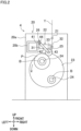
- FIG. 2 is a front view of a winding device;
- FIGS. 3A and 3B are explanatory views showing angle adjustment of a contact roller;
- FIGS. 4A to 4D are reference views schematically showing a cause of displacement between a traverse region and a bobbin in a predetermined direction;
- FIG. 5 is an explanatory view showing an error of a bobbin length;
- FIG. 6 is an explanatory view showing a movement drive unit;
- FIGS. 7A to 7C are explanatory views showing control examples of the movement drive unit;
- FIGS. 8A to 8D are reference views showing a shape of a package; and
- FIGS. 9A and 9B are explanatory views showing a spun yarn take-up machine according to a modification.
DESCRIPTION OF THE PREFERRED EMBODIMENTS
-
Next, embodiments of the present invention will be described. The left-right direction in FIG. 1 on the paper surface is defined as a front-rear direction. A direction in which gravity acts is defined as an up-down direction (vertical direction), and a direction (direction perpendicular to the paper surface) orthogonal to both the front-rear direction and the up-down direction is defined as a left-right direction.
(Schematic configuration of spun yarn take-up machine)
-
A spun yarn take-up machine 1 (yarn winder of the present invention) according to the present embodiment will be described with reference to FIG. 1. FIG. 1 is a profile of the spun yarn take-up machine 1. The spun yarn take-up machine 1 includes a take-up unit 3 that takes up a yarn Y spun from a spinning apparatus 2, and a winding device 4 that winds the yarn Y taken up by the take-up unit 3 around a plurality of bobbins B.
-
The take-up unit 3 includes a first godet roller 11 and a second godet roller 12. The take-up unit 3 is configured to take up, by the first godet roller 11 and the second godet roller 12, the yarn Y spun from the spinning apparatus 2 and send the yarn Y to the winding device 4. The first godet roller 11 is a roller whose rotational axis direction is substantially parallel to the left-right direction. The first godet roller 11 is arranged below the spinning apparatus 2 and above the front end portion of the winding device 4. The first godet roller 11 is rotationally driven by a motor not illustrated. A yarn regulating guide 13 is arranged immediately above the first godet roller 11. The yarn regulating guide 13 is, for example, a known comb teeth yarn guide. The yarn regulating guide 13 is configured to regulate the interval between the adjacent yarns Y to a predetermined value.
-
The second godet roller 12 is a roller whose rotational axis direction is substantially parallel to the left-right direction. The second godet roller 12 is arranged above and rear as compared with the first godet roller 11. The second godet roller 12 is rotationally driven by a motor not illustrated. The second godet roller 12 is movably supported by a guide rail 14. The guide rail 14 extends obliquely upward and rearward. The second godet roller 12 is configured to be movable along the guide rail 14 by a movement mechanism not illustrated. Thus, the second godet roller 12 is movable between a position (see solid line) at which the yarn Y is wound around the bobbin B and a position (see dashed line) at which yarn threading is carried out, the position being disposed in proximity to the first godet roller 11.
(Winding device)
-
The configuration of the winding device 4 will be described with reference to FIGS. 1 and 2. FIG. 2 is a front view of the winding device 4. The winding device 4 includes a base 20, a plurality of fulcrum guides 21, a traverse device 22, a turret 23, two bobbin holders 24, a contact roller 25, a supporting member 26, an angle adjustment unit 27, and a controller 28. The winding device 4 is configured to form a plurality of packages P by winding the plurality of yarns Y around the plurality of bobbins B held by the bobbin holder 24 while traversing the plurality of yarns Y fed from the take-up unit 3 in the front-rear direction by the traverse device 22. Hereinafter, the operation of winding the yarn Y around the bobbin B will be referred to as a winding operation.
-
As shown in FIG. 1, the base 20 includes a base body 20a arranged upright at a rear portion of the winding device 4, and a frame 20b fixed to an upper portion of the base body 20a and extending forward. The turret 23 and the like are supported on the base body 20a. The frame 20b is, for example, a hollow columnar member. The contact roller 25 extending along the front-rear direction is supported by the frame 20b via the supporting member 26 and the angle adjustment unit 27 (details will be described later).
-
The plurality of fulcrum guides 21 are yarn guides serving as fulcrums when the plurality of yarns Y are each traversed. The plurality of fulcrum guides 21 are arranged corresponding to the plurality of yarns Y, respectively. The plurality of fulcrum guides 21 are arrayed along the front-rear direction.
-
The
traverse device 22 is configured to traverse the plurality of yarns Y along the front-rear direction. The
traverse device 22 includes a
housing 31, a plurality of traverse guides 32 arranged corresponding to the plurality of yarns Y, respectively, and a traverse motor 33 (see
FIG. 2). The
traverse device 22 is, for example, a wing type traverse device described in
JP 2019-214474 A (The wing guide described in
JP 2019-214474 A corresponds to the
traverse guide 32 of the present embodiment). Each of the plurality of traverse guides 32 includes, for example, two wing guides 34 (see
FIG. 1. FIG. 1 shows only one
wing guide 34 corresponding to each traverse guide 32). The two wing guides 34 are configured to be rotationally driven in directions opposite to each other when viewed from a predetermined rotational axis direction. Each
traverse guide 32 is configured to traverse each yarn Y by the two wing guides 34 that are being rotationally driven by the
traverse motor 33. In such a configuration, a traveling range (traverse region) in the front-rear direction of the yarn Y accompanying the drive of the plurality of traverse guides 32 is fixed with respect to the
housing 31. In other words, the center position of the traverse region of each
traverse guide 32 does not move with respect to the
traverse device 22. The length of the traverse region in the axial direction is constant. In the present embodiment, all the traverse guides 32 are included in the
traverse device 22. The
traverse motor 33 is a common drive source of the plurality of traverse guides 32. The plurality of traverse guides 32 are simultaneously driven at least in the front-rear direction by the
traverse motor 33. Thus, the yarn Y threaded to each
traverse guide 32 is traversed simultaneously with each fulcrum guide 21 as a fulcrum.
-
The turret 23 is a disc-shaped member whose axial direction is substantially parallel to the front-rear direction. The turret 23 is rotatably supported by the base body 20a. The turret 23 is rotationally driven by a turret motor not illustrated. The turret 23 cantilevers the two bobbin holders 24. The turret 23 moves the two bobbin holders 24 by rotating about a rotation axis substantially parallel to the front-rear direction. The turret 23 is configured such that the positions of the two bobbin holders 24 can be exchanged. Thus, the bobbin B can be replaced with respect to the other bobbin holder 24 while the yarn is being wound around the bobbin B mounted to one bobbin holder 24. The turret 23 is configured to be rotatable with an increase in the amount of the wound yarn Y during the winding operation (see the arrow in FIG. 2).
-
The two bobbin holders 24 are configured such that the plurality of bobbins B can be mounted to each of the bobbin holders. The two bobbin holders 24 are rotatably supported by the turret 23 supported by the base body 20a. The two bobbin holders 24 are cantilevered by the turret 23. The two bobbin holders 24 are arranged so as to be point-symmetric with each other across the center point of the turret 23 when viewed from the front-rear direction. That is, for example, when one bobbin holder 24 is located at the uppermost position, the other bobbin holder 24 is located at the lowermost position. The two bobbin holders 24 extend forward from the turret 23. The axial direction (hereinafter, predetermined direction) in which the two bobbin holders 24 extend is substantially parallel to the front-rear direction. As will be described later, the predetermined direction slightly fluctuates during the winding operation. The plurality of bobbins B individually provided in the plurality of yarns Y are mounted to each bobbin holder 24 side by side in the axial direction. In the present embodiment, the number of bobbins B that can be mounted to one bobbin holder 24 is 16 (see FIG. 1), but the present invention is not limited thereto. Each of the two bobbin holders 24 is rotationally driven by an individual winding motor (not illustrated). The two bobbin holders 24 are located below the traverse device 22.
-
While the yarn Y is wound around the bobbin B mounted to one bobbin holder 24 to form the package P, the weight of the package P increases (the package P becomes thicker) with the increase in the amount of the yarn Y. As described above, the bobbin holder 24 is cantilevered. Therefore, the attitude of the bobbin holder 24 is maintained substantially horizontal immediately after the start of the winding operation (see FIG. 3A), but as the package P becomes thicker, the bobbin holder 24 is bent downward by the weight of the package P (see FIG. 3B). The bending amount of the bobbin holder 24 at this time is larger toward the leading end side in the axial direction of the bobbin holder 24.
-
The contact roller 25 is disposed immediately above the upper bobbin holder 24. The axial direction of the contact roller 25 is substantially parallel to the front-rear direction. The contact roller 25 is configured to apply a contact pressure to the surfaces of the plurality of packages P supported by the upper bobbin holder 24 and adjust the shape of the package P.
-
The supporting member 26 is configured to support the contact roller 25 and the traverse device 22. As shown in FIGS.
-
1 and 2, the supporting member 26 is swingably attached to the frame 20b, for example. The supporting member 26 includes, for example, a swing shaft 41, a pair of arm portions 42, and a roller support shaft 43. The swing shaft 41 extends substantially in the front-rear direction. The arm portions 42 are respectively fixed to both end portions of the swing shaft 41 in the front-rear direction. The swing shaft 41 is configured to swing the pair of arm portions 42 and the roller support shaft 43 with the extending direction of the swing shaft 41 as a swing shaft direction. The swing shaft 41 is rotatably supported by an attaching member 44 attached to the front end portion of the frame 20b and a slider 46 described later arranged in the vicinity of the rear end portion of the frame 20b. The attaching member 44 rotatably supports the swing shaft 41. The attaching member 44 swingably supports the swing shaft 41 in the up-down direction with the attaching member 44 as the swing shaft center by, for example, a shaft member not illustrated. Due to this, the angle of the swing shaft 41 with respect to the horizontal direction can be adjusted by the angle adjustment unit 27 (details will be described later). The pair of arm portions 42 are fixed to both end portions of the swing shaft 41 in the front-rear direction. The pair of arm portions 42 extend from the swing shaft 41 in a direction substantially perpendicular to the front-rear direction. The housing 31 of the traverse device 22 is fixed to an intermediate portion of the pair of arm portions 42. The roller support shaft 43 is fixed to the end portions of the pair of arm portions 42 on the side opposite to the swing shaft 41. The roller support shaft 43 is a shaft disposed substantially parallel to the swing shaft 41. The roller support shaft 43 rotatably supports the contact roller 25.
-
The angle adjustment unit 27 is configured to change the angle of the supporting member 26 with respect to the horizontal direction. The angle adjustment unit 27 includes, for example, a ball screw mechanism 45. The ball screw mechanism 45 includes the slider 46 and is configured to be able to move the slider 46 in the up-down direction. The slider 46 rotatably supports a rear end portion of the swing shaft 41. By moving the rear end portion of the swing shaft 41 along the up-down direction by such the ball screw mechanism 45, it is possible to change the angle of the swing shaft 41 with respect to the horizontal direction. Due to this, the angle of the supporting member 26 with respect to the horizontal direction changes, and as a result, the angle of the contact roller 25 and the traverse device 22 with respect to the horizontal direction changes. Due to this, the angle of the contact roller 25 and the traverse device 22 can be caused to follow the bending of the bobbin holder 24 accompanying the thickening of the package P.
-
The controller 28 includes a CPU, a ROM, and a RAM. The controller 28 controls each unit by the CPU according to a program stored in the ROM. Specifically, the controller 28 controls a turret motor (not illustrated), the traverse motor 33, the ball screw mechanism 45, and the like. The controller 28 functions as a first controller, a second controller, a third controller, and a fourth controller of the present invention.
-
In the winding device 4 having the configuration described above, when the upper bobbin holder 24 is rotationally driven, the yarn Y traversed by the traverse guide 32 is wound around the bobbin B to form the package P. While the package P is formed, the contact roller 25 comes into contact with the surface of the package P to apply a contact pressure, so that the shape of the package P is adjusted. The turret 23 is rotated in the direction of the arrow in FIG. 2 as the diameter of the package P becomes larger (the package P becomes thicker) by winding the yarn Y around the bobbin B. This increases the distance between the bobbin holder 24 on which the bobbin B around which the yarn Y is wound is mounted and the contact roller 25. Since the contact roller 25 is swingable about the swing shaft 41, the contact roller 25 swings following the movement of the bobbin holder 24 and the package P. This maintains the contact between the contact roller 25 and the package P.
-
As described above, immediately after the start of the winding operation, the attitude of the bobbin holder 24 is maintained substantially horizontal (see FIG. 3A). As the package P becomes thicker, the bobbin holder 24 is bent downward by the weight of the package P (see FIG. 3B). In other words, the axial direction (predetermined direction) of the bobbin holder 24 changes with respect to the horizontal direction with the lapse of time from the start of the winding operation. In such a situation, when the angle between the bobbin holder 24 and the contact roller 25 changes, the contact pressure by the contact roller 25 varies among the plurality of packages P, and as a result, the quality varies among the plurality of packages P. In order to solve such a problem, the controller 28 controls the angle adjustment unit 27 during the winding operation to change the angle of the supporting member 26 with respect to the horizontal direction. This maintains the bobbin holder 24 and the contact roller 25 substantially parallel to each other. As described above, the traverse device 22, together with the contact roller 25, is supported by the supporting member 26. Therefore, even if the bobbin holder 24 is inclined from the horizontal direction, the moving direction of the yarn Y accompanying the driving of the traverse guide 32 can substantially coincide with the predetermined direction. Thus, it is also possible to suppress a problem that the winding angle (helix angle) when the yarn Y is wound around the bobbin B displaces from the target value, for example.
-
However, the inventor of the present application has found that also in the above configuration, a new problem is becoming apparent as the bobbin holder 24 is further lengthened. Hereinafter, a specific description will be given with reference to FIGS. 4A to 4D and 5. FIG. 4A is an explanatory view showing a positional relationship between the bobbin B before the start of the winding operation and a movable range (traverse region R) of the yarn Y accompanying the drive of the traverse guide 32. FIG. 4B is an explanatory view showing a positional relationship between the bobbin B and the traverse region R after a predetermined time has elapsed from the start of the winding operation. FIG. 4C is a view more schematically showing the positional relationship in FIG. 4A. FIG. 4D is a view more schematically showing the positional relationship in FIG. 4B. FIG. 5 is an explanatory view related to an error in the length of the bobbin B mounted to the bobbin holder 24. In FIGS. 4A to 4D, a side toward the front side is defined as one side in a predetermined direction. A side toward the rear side is defined as the other side in the predetermined direction.
-
To begin with, a problem caused by the bending of the bobbin holder 24 as described above will be described. Before the start of the winding operation, the bobbin B and the traverse region R have a predetermined positional relationship in the front-rear direction (see FIG. 4A). Thus, immediately after the start of the winding operation, the yarn Y is wound around a predetermined region of the outer circumference of the bobbin B in the predetermined direction. However, when the package P gets thicker and the bobbin holder 24 is bent (when the predetermined direction is inclined with respect to the front-rear direction), even if the angles of the contact roller 25 and the traverse device 22 are adjusted, the traverse region R gradually displaces to the other side with respect to the bobbin B in the predetermined direction. The inventor of the present application has found that this unintentionally distorts the shape of the package P to the other side in the predetermined direction (see FIG. 4B).
-
Such a phenomenon will be more schematically described with reference to FIGS. 4C and 4D. A simple example will be given below. It is assumed that the swing shaft 41 described above is arranged along a line segment L1. A predetermined point of the front end portion of the swing shaft 41 is defined as a point P1a. A predetermined point at the rear end portion of the swing shaft 41 is assumed to be the rear end of the line segment L1, and the point at the rear end of the line segment L1 is assumed to be a point P1b. It is assumed that the bobbin holder 24 is disposed along a line segment L2 disposed below the line segment L1. A predetermined point of the front end portion (leading end portion) of the bobbin holder 24 is defined as a point P2a. A predetermined point of the rear end portion (base end portion) of the bobbin holder 24 is defined as a point P2b. For simplification of explanation, it is assumed that the length of the line segment L1 and the length of the line segment L2 are the same. Before the winding is started (see FIG. 4C), the positions of the line segment L1 and the line segment L2 are the same in the front-rear direction. The predetermined direction is parallel to the front-rear direction. In this case, the positions of the point P1a and the point P2a coincide with each other in the predetermined direction (see the two-dot chain line in FIG. 4C). Next, when the package P gets thicker and the bobbin holder 24 is bent, the line segment L2 can be considered to have been rotated downward by a predetermined angle about the point P2b. At this time, the predetermined direction is inclined by a predetermined angle with respect to the front-rear direction. In such a state, when the predetermined direction is focused on, the point P2a is displaced to one side with respect to the point P1a (see the two-dot chain line in FIG. 4D). In such a case, even if the angle of the line segment L1 is changed according to the change in angle of the line segment L2, it is not sufficient to coincide with the position of the line segment L1 in the predetermined direction with the position of the line segment L2 in the predetermined direction. Even if the line segment L1 is rotated about the point P1a, or even if the line segment L1 is rotated about the point P1b, such position displacement cannot be resolved.
-
Although not illustrated in detail, a more serious problem can occur depending on the orientation of the bobbin B mounted on the bobbin holder 24. Generally, a slit S on which the yarn Y is threaded is formed at one end portion of the bobbin B in the axial direction of the bobbin B (see the broken lines in FIGS. 4A and 4B). In general, the traverse region R is set so as to be close to a side where the slit S is not formed in the axial direction of the bobbin B. That is, on the side where the slit S is not formed in the bobbin B, the margin part in which the yarn is not wound is narrow. Furthermore, in general, as the package P becomes thicker, a force is applied inward in the radial direction of the package P due to the tension of the yarn Y wound into the package P. Due to this, the radially inner portion of the package P tends to bulge in the predetermined direction. Therefore, when the bobbin B is mounted to the bobbin holder 24 such that the slit S is arranged on one side in the predetermined direction, the risk that the yarn Y tends to protrude from the bobbin B on the other side in the predetermined direction of the bobbin B increases.
-
Next, a problem caused by an error in the length in the axial direction of the bobbin B mounted to the bobbin holder 24 will be described. Generally, in each bobbin B, an error in the length in the axial direction of the bobbin B is small. However, when the bobbin holder 24 is lengthened and the number of bobbins B mounted to the bobbin holder 24 at one time increases, the error increases accordingly. For example, a case where a relatively short bobbin B (bobbin B1) is mounted to the bobbin holder 24 as shown on the upper side of FIG. 5 and a case where a relatively long bobbin B (bobbin B2) is mounted to the bobbin holder 24 as shown on the lower side of FIG. 5 are assumed. In this case, a difference dLt between the total value (entire length) of the lengths of the plurality of bobbins B1 and the entire length of the plurality of bobbins B2 increases with an increase in the number of bobbins B mounted at one time on the bobbin holder 24. In such a case, the positional relationship between the bobbin B and the traverse region R (see FIGS. 4A and 4B) in the predetermined direction cannot be appropriately maintained, and a malfunction is liable to occur in the formation of the package P.
-
In order to suppress the occurrence of the problem of formation of the package P caused by the fluctuation in the relative position between the traverse region R and the bobbin B in the predetermined direction as described above, the winding device 4 of the spun yarn take-up machine 1 of the present embodiment includes a movement drive unit 50 as follows.
(Movement drive unit)
-
The configuration of the movement drive unit 50 will be described with reference to FIG. 6. FIG. 6 illustrates also the members accommodated in the base body 20a so that they are visible. The movement drive unit 50 is to move the entire traverse device 22 in at least the predetermined direction. Hereinafter, an example of the movement drive unit 50 will be described. The movement drive unit 50 includes, for example, a ball screw mechanism 51 (linear actuator of the present invention). The ball screw mechanism 51 is configured to be able to adjust a position of the traverse device 22 in the predetermined direction. The ball screw mechanism 51 is connected to the rear end portion of the swing shaft 41 of the supporting member 26. The ball screw mechanism 51 includes a moving motor 52, a screw shaft 53, and a slider 54.
-
The moving motor 52 is configured to rotationally drive the screw shaft 53. The moving motor 52 is, for example, a known servo motor or stepping motor. The screw shaft 53 is fixed to a rotation shaft of the moving motor 52. The moving motor 52 is coupled to the slider 46 of the angle adjustment unit 27 described above by a connection member 55, for example. Due to this, the position of the moving motor 52 is fixed with respect to the slider 46. Therefore, the moving motor 52 can move following the up-down movement of the slider 46 (i.e., following the change in angle of the swing shaft 41). The moving motor 52 is electrically connected to the controller 28, and is driven and controlled by the controller.
-
The screw shaft 53 rotates to move the slider 54 in at least the predetermined direction. The extending direction of the screw shaft 53 is substantially parallel to the extending direction of the swing shaft 41 of the supporting member 26 described above. A male screw is formed on the screw shaft 53. The screw shaft 53 is screwed with the slider 54. By moving in the extending direction of the screw shaft 53, the slider 54 moves the supporting member 26 in at least the predetermined direction. A female screw is formed on the slider 54. The slider 54 is screwed with the screw shaft 53. The slider 54 is attached to the rear end portion of the swing shaft 41 of the supporting member 26. This enables the slider 54 to move following the change in angle of the swing shaft 41. As described above, the ball screw mechanism 51 follows the change in angle (i.e., the change in angle of the supporting member 26) of the swing shaft 41 as a whole. This avoids an excessive force from being applied to the ball screw mechanism 51.
-
Furthermore, the winding device 4 is also configured as follows in order to make the supporting member 26 movable in at least the predetermined direction. To begin with, the slider 46 of the angle adjustment unit 27 slidably supports the rear end portion of the swing shaft 41 in the predetermined direction. As a specific example, a through hole 46a penetrating in the axial direction of the swing shaft 41 is formed in the slider 46, and the swing shaft 41 is inserted into the through hole 46a. Similarly, the above-described attaching member 44 (see FIG. 1 and the like) slidably supports the front end portion of the swing shaft 41 in the predetermined direction.
-
In the movement drive unit 50 having the above configuration, when the screw shaft 53 is rotationally driven by the moving motor 52, the slider 54 moves in the extending direction of the screw shaft 53 (see the arrow in FIG. 6). Due to this, the entire supporting member 26 including the swing shaft 41 moves integrally with the slider 54 in the extending direction of the swing shaft 41. As a result, the entire traverse device 22 attached to the supporting member 26 moves at least in the predetermined direction. When the extending direction of the screw shaft 53 and the extending direction of the swing shaft 41 are substantially parallel to the axial direction (predetermined direction) of the bobbin holder 24, the traverse device 22 moves along the predetermined direction. In the present embodiment, the contact roller 25 also moves at least in the predetermined direction along with the movement of the supporting member 26.
(Position control of traverse region)
-
Next, control of the movement drive unit 50 by the controller 28 (i.e., position control of the traverse region R described above) will be described with reference to FIGS. 7A to 7C and FIGS. 8A to 8D. FIGS. 7A to 7C are explanatory views showing control examples of the movement drive unit 50 by the controller 28 (more specifically, movement of the traverse region R). FIG. 8A is a profile of the package P. FIG. 8B is a cross section of the package P shown in FIG. 8A. FIG. 8C is a cross section of the package P according to a second control example (1) described later. FIG. 8D is a cross section of the package P according to a second control example (2) described later.
-
To begin with, the control carried out before the start of the winding of the yarn Y around the plurality of bobbins B (before the start of the winding operation) will be described. Before the start of the winding operation, the controller 28 controls the movement drive unit 50 based on the information on the entire length of the plurality of bobbins B, and adjusts the position of the traverse region R at least in the predetermined direction (see FIG. 7A). An example of the adjustment method is as follows. The controller 28 acquires information related to the entire length of the plurality of bobbins B by some means or method before the start of the winding operation. The information may be input to the controller 28 by, for example, an operator. Alternatively, the information related to the entire length of the plurality of bobbins B may be sent, for example, from a higher computer electrically connected to the controller 28 to the controller 28. Based on such information of the entire length, the controller 28 can acquire position information in the predetermined direction of a predetermined part of the plurality of bobbins B (e.g., the front end surface of the bobbin B arranged on the foremost side). In this case, the controller 28 corresponds to a position information acquisition unit of the present invention. Alternatively, the winding device 4 may include a sensor not illustrated that detects a position in the predetermined direction of a predetermined part of the plurality of bobbins B. The sensor may transmit information of the position to the controller 28. In this case, the sensor corresponds to the position information acquisition unit of the present invention.
-
After acquiring the information of the entire length of the plurality of bobbins B, the controller 28 derives the adjustment amount of the traverse region R based on the information. The adjustment amount may be a value obtained by dividing the difference between the entire length and the reference length by 2, for example. Based on information of the adjustment amount, the controller 28 controls the movement drive unit 50 before the start of the winding operation to move the traverse device 22, and adjusts the position of the traverse region R at least in the predetermined direction. This can optimize the position of the traverse region R in the predetermined direction with respect to the bobbin B mounted to the center part of the bobbin holder 24 in the front-rear direction. The controller 28 stores the thus optimized position of the traverse region R as the position (reference position) of the traverse region R at the start of the winding operation. In this case, the traverse region R can slightly displace in the predetermined direction with respect to the bobbin B arranged on the foremost side and the bobbin B arranged on the rearmost side. However, compared to the case where the adjustment is not performed at all, the position displacement in the predetermined direction between, for example, the bobbin B arranged on the foremost side and the traverse region R can be halved. Thus, as a whole, it is possible to suppress an extreme position displacement between the traverse region R and the bobbin B before the start of the winding operation. Thus, before the start of the winding operation, the movement drive unit 50 is controlled so as to reduce the position displacement in the predetermined direction between the traverse region R and the bobbin B. The specific timing of the position adjustment of the traverse region R before the start of the winding operation as described above may be, for example, immediately before the yarn Y is threaded to the slit S of each bobbin B. Alternatively, the position adjustment may be carried out, for example, in a period from the completion of the yarn threading to the slit S to the start of the winding operation.
-
Next, position control in the predetermined direction of the traverse region R during the winding operation will be described. The controller 28 moves the traverse region R during the winding operation with respect to the position (reference position described above) of the traverse region R at the start of the winding operation. The position control is carried out during the winding operation, simultaneously with the control of the angle adjustment of the contact roller 25, for example. Hereinafter, two control examples will be described. Broadly speaking, the first control example (see FIG. 7B) is a control example of maintaining substantially the same positional relationship in the predetermined direction between the traverse region R and the bobbin B. The second control example (see FIG. 7C) is a control example in which the traverse region R is gradually moved toward the slit S side in the predetermined direction during the winding operation.
-
In the first control example and the second control example, a control procedure is common. To begin with, the controller 28 acquires target information related to a target position (or a movement amount of the supporting member 26) in the predetermined direction of the traverse region R in which the bending of the bobbin holder 24 accompanying the thickening of the package P and the angle adjustment of the supporting member 26 with respect to the bending are taken into consideration. The information may be stored in advance in the RAM of the controller 28 as, for example, a table in which time and position (or movement amount) are associated with each other. Alternatively, the information may be derived based on a predetermined calculation formula or the like using a detection result by a sensor (not illustrated) that detects information on the bending amount of the bobbin holder 24 and a detection result by a sensor (not illustrated) that detects information on the angle of the supporting member 26. Based on such target information, the controller 28 appropriately controls the movement drive unit 50, thereby performing the position control in the predetermined direction of the traverse region R during the winding operation.
-
The specific content of the target information described above is different from each other between the first control example and the second control example. In the first control example, the target information is determined such that a positional relationship in the predetermined direction between the traverse region R of a certain traverse guide 32 and the bobbin B corresponding to the traverse guide 32 does not change with time (i.e., so that the relative position in the predetermined direction does not change with time). That is, not only before the start of the winding operation but also during the winding operation, the movement drive unit 50 is controlled so as to reduce the positional displacement in the predetermined direction between the traverse region R and the bobbin B. Thus, deformation of the package P in the predetermined direction is suppressed (see FIG. 7B). More specifically, as shown in FIG. 8A for example, the shape of an end face E1 on one side in the predetermined direction of the package P and the shape of an end face E2 on the other side in the predetermined direction can be made symmetrical in the predetermined direction.
-
On the other hand, in the second control example, the target information is determined such that the traverse region R gradually displaces to at least one side (side where the slit S is formed) in the predetermined direction with respect to the bobbin B (see the full-line arrow in FIG. 7C). This causes the outer circumference of the package P to be intentionally slightly displaced to one side in the predetermined direction (see FIG. 7C).
-
Before the second control example is explained in more detail, a purpose of carrying out the second control example will be explained. As described above, in general, as the package P becomes thicker, the radially inner portion of the package P tends to bulge in the predetermined direction. That is, a compressive force generated by the yarn tension at the radially outer part of the package P acts on the radially intermediate portion (intermediate layer portion) of the yarn layer, and the bulge is generated. Due to this, the end faces E1 and E2 bulge in the predetermined direction (see FIG. 8A and the like). For example, when the positional relationship between the bobbin B and the traverse region R is maintained constant in the predetermined direction from the start to the end of the winding operation (see the two-dot chain line in the package P of FIG. 8B), the end faces E1 and E2 bulge to the same extent in the predetermined direction (see FIGS. 8A and 8B). In this case, when the length in the predetermined direction of the traverse region R is Lr, a size (bulge amount of the end faces E1 and E2) in the predetermined direction of the bulge is dLr, and the length in the predetermined direction of the yarn layer of the package P is Lr2, "Lr2 = Lr + 2 × dLr" is established. As shown in the cross section of FIG. 8B (cross section of the package P shown in FIG. 8A), the radially intermediate portion (intermediate layer portion) of the yarn layer tends to bulge the most in the predetermined direction. Since such a bulge occurs, when the bobbin B is mounted to the bobbin holder 24 such that the slit S is arranged on one side in the predetermined direction, there is a high risk that the yarn Y tends to protrude from the bobbin B on the other side in the predetermined direction of the bobbin B. Alternatively, even if a serious problem that the yarn Y protrudes from the bobbin B does not occur, the following problem may also occur when the margin part of the end portion on the other side in the predetermined direction of the bobbin B is narrow. Generally, the plurality of completed packages P are transported in a state of being placed on a tray (not illustrated) on which the plurality of packages P can be placed. Here, a plurality of holes (not illustrated) into which the end portions on the other side in the predetermined direction of the plurality of bobbins B can be inserted are formed on a placement surface (not illustrated) of the tray. In other words, the plurality of packages P placed on the tray are transported in a state where the axial direction of each bobbin B is substantially parallel to the up-down direction and the end face of the package P is substantially parallel to the horizontal direction. When each bobbin B is firmly inserted into each hole, the plurality of packages P are stably transported. However, if the margin part is narrow, the bobbin B is not firmly inserted into the hole, and the package P easily falls. When the bobbin B is not firmly inserted into the hole as described above, there is a possibility that the package P is displaced in the horizontal direction on the placement surface during transportation, comes into contact with the adjacent package P, and the package P is damaged.
-
In this regard, the bulge of the end face E2 on the other side in the predetermined direction of the package P can be reduced by carrying out the second control example during the winding operation. In the second control example, during the winding operation, the controller 28 (1) moves the traverse device 22 only to one side in the predetermined direction, or (2) moves the traverse device 22 to one side in the predetermined direction and then to the other side in the predetermined direction.
-
To begin with, the control of the above (1) will be described. The controller 28 controls the movement drive unit 50 to gradually move the traverse device 22 to one side in the predetermined direction from immediately after the start of the winding operation or after a predetermined time has lapsed from the start of the winding operation (see the full-line arrow in FIG. 7C). The movement amount of the traverse device 22 at this time is larger than the movement amount of the traverse device 22 in the first control example, for example. More specifically, the traverse region R immediately before the end of the winding operation is displaced to one side in the predetermined direction by a predetermined amount with respect to the traverse region R at the start of the winding operation. The predetermined amount may be, for example, dLr described above (see a two-dot chain line in the package P of FIG. 8C), or may be another value. Such control enables the position of the intermediate layer in the predetermined direction to displace to one side. As a result, the bulge amount of the end face E1 increases, and the bulge amount of the end face E2 is suppressed (see FIG. 8C). Therefore, since the bobbin B can be firmly inserted into the hole of the tray, the package P can be stably transported.
-
Next, the control of the above (2) will be described. In the control of (1) above, the radially outer part of the package P is liable to be greatly biased to one side in the predetermined direction, which causes concern of collapsing the shape of the package P. If the traverse region R moves too much to one side in the predetermined direction, the yarn layer of the package P is also liable to protrude to one side in the predetermined direction from the end face of the bobbin B. Therefore, the control of the above (2) may be performed instead of the control of the above (1). As an example, to begin with, the controller 28 controls the movement drive unit 50 to gradually move the traverse device 22 to one side in the predetermined direction from immediately after the start of the winding operation or after a predetermined time has lapsed from the start of the winding operation (see the full-line arrow in FIG. 7C). Thereafter, the controller 28 gradually moves the traverse device 22 to the other side in the predetermined direction (see the broken line arrow in FIG. 7C). For example, the controller 28 controls the movement drive unit 50 so that the traverse region R when the weight of the package P becomes approximately half of the target weight is displaced by dLr to one side in the predetermined direction relative to the traverse region R at the start of the winding operation (see the two-dot chain line in the package P of FIG. 8D). Thereafter, the controller 28 controls the movement drive unit 50 so that the position in the predetermined direction of the traverse region R when the weight of the package P reaches the target weight substantially coincides with the position of the traverse region R in the predetermined direction at the start of the winding operation (see two-dot chain line in FIG. 8D). This can suppress the bulge amount of the end face E2, and suppress the radially outer part of the package P from being biased to one side in the predetermined direction as compared with the control of (1). It is most preferable that by such control, as shown in FIG. 8D, ideally the bulge amount of the end face E1 in the predetermined direction becomes 2 × dLr and the bulge amount of the end face E2 in the predetermined direction becomes zero. However, the present invention is not limited thereto, and by reducing the bulging amount, the margin part of the end portion on the other side in the predetermined direction of the bobbin B can be suppressed from being narrowed.
-
As described above, by the movement drive unit 50 moving the traverse device 22 in at least the predetermined direction, the traveling range (traverse region R) of the yarn Y accompanying the drive of the traverse guide 32 included in the traverse device 22 can be moved in the predetermined direction. This can suppress the fluctuation in the relative position between the traverse region R and the bobbin B in the predetermined direction. Therefore, it is possible to suppress the occurrence of the problem of formation of the package P caused by the fluctuation in the relative position between the traverse region R and the bobbin B.
-
As in the present embodiment, in the configuration in which the traverse region R is fixed with respect to the traverse device 22 (specifically, a wing type traverse device), it is particularly effective that the movement drive unit 50 is provided.
-
The traverse device 22 includes all of the plurality of traverse guides 32. This can move the traverse regions R of all the traverse guides 32 by one movement drive unit 50. Therefore, the structure of the spun yarn take-up machine 1 can be simplified as compared with a configuration that requires a plurality of movement drive units (not illustrated).
-
The movement drive unit 50 includes the ball screw mechanism 51 that can adjust the position of the traverse device 22 in the predetermined direction. This allows the position of the traverse device 22 to be precisely adjusted as compared with a configuration in which the traverse device 22 is moved by the propulsive force such as an air cylinder (not illustrated), for example.
-
The angle adjustment unit 27 adjusts the angle of the traverse device 22 and the contact roller 25, thereby suppressing the fluctuation in the contact pressure among the packages P due to the thickening of the plurality of packages P. However, if the angle is simply adjusted alone, the traverse region R is liable to be displaced in the predetermined direction with respect to the bobbin B, and the shape of the package P is liable to collapse. In this regard, in the present embodiment, displacement of the traverse region R in the predetermined direction with respect to the bobbin B can be suppressed by the movement drive unit 50, and hence the collapse of the shape of the package P can be effectively suppressed.
-
Similarly to the angle adjustment unit 27, the movement drive unit 50 is configured to move the supporting member 26. Therefore, the design can be simplified as compared with the case where the spun yarn take-up machine 1 is configured to move the traverse device 22 with respect to the supporting member 26.
-
The position adjustment of the traverse region R is carried out during the winding operation. Therefore, the shape of the package P can be effectively adjusted, or the shape of the package P can be freely changed to some extent.
-
The spun yarn take-up machine 1 includes a position information acquisition unit (controller 28 or a sensor not illustrated). Thus, the displacement amount of the traverse region R in the predetermined direction caused by an error in the length of the bobbin B can be found based on the position information. Therefore, the displacement of the traverse region R from the bobbin B in the predetermined direction can be compensated using the position information.
-
The position displacement of the traverse region R from the bobbin B caused by an error in the length of the bobbin B can be found in advance by the position information acquisition unit before the start of the winding operation. The controller 28 controls the movement drive unit 50 before the start of the winding operation based on the position information. Therefore, the position displacement as described above can be effectively compensated.
-
As the first control example by the controller 28, the controller 28 controls the movement drive unit 50 so as to reduce the positional displacement in the predetermined direction between the traverse region R and the bobbin B. Such control is particularly effective when it is desired to make the shape of the package P symmetrical in the predetermined direction.
-
As the second control example by the controller 28, the traverse region R is purposely moved to one side in the predetermined direction during the winding operation. Thus, by allowing an increase in the bulge amount of the end face E1 on one side (side where the margin of the bobbin B is wide) in the predetermined direction of the package P, the bulge amount of the end face E2 on the other side (side where the margin of the bobbin B is narrow) in the predetermined direction of the package P can be reduced accordingly. Therefore, since the margin on the other side in the predetermined direction of the bobbin B can be suppressed from narrowing, the risk of the yarn Y protruding from the bobbin B and the like can be reduced.
-
As described above, during the winding operation, the controller 28 may move the traverse device 22 to one side in the predetermined direction and then to the other side in the predetermined direction. Thus, the radially outer part of the package P can be suppressed from being biased to one side in the predetermined direction while suppressing the margin on the other side in the predetermined direction of the bobbin B from being narrowed.
-
Next, modifications in which changes are added to the embodiments will be described. However, those having the same configurations as those of the above embodiments are given the same reference numerals, and the description thereof will be appropriately omitted.
- (1) The movement drive unit 50 (see FIG. 6) may be provided in a spun yarn take-up machine 1a as shown in FIG. 9A. In the spun yarn take-up machine 1a, two winding devices 4A and 4B including the same function as that of the winding device 4 of the spun yarn take-up machine 1 are arranged substantially symmetrically regarding the left-right direction. For example, the winding device 4A has the identical structure to that of the winding device 4 described above. The winding device 4B has a structure substantially symmetrical with the winding device 4A regarding the left-right direction. The winding device 4A includes a bobbin holder 24A, and the winding device 4B includes a bobbin holder 24B. Rear end portions of the bobbin holders 24A and 24B are cantilevered. As shown in FIG. 9B, a plurality of bobbins B (bobbins BA) mounted to the bobbin holder 24A and a plurality of bobbins (bobbins BB) mounted to the bobbin holder 24B are arranged in opposite directions to each other in the front-rear direction. That is, the slit S of the bobbin BA is located on the front side, and the slit S of the bobbin BB is located on the rear side. In such a configuration, when the bobbin holder 24A and the bobbin holder 24B are rotationally driven in opposite directions to each other, the winding direction of the yarn Y wound around the bobbin BA and the winding direction of the yarn Y wound around the bobbin BB can be made the same. Thus, the package P described above can be formed by both the winding device 4A and the winding device 4B. Here, in a case where the movement drive unit 50 (see FIG. 6) is not provided, when the bobbin holders 24A and 24B are bent downward accompanying the thickening of the package P, the following problem can occur due to the orientation of the bobbin BA and the orientation of the bobbin BB being opposite to each other. That is, in the winding device 4A, the package P can be distorted to the side opposite to the slit S in the predetermined direction. On the other hand, in the winding device 4B, the package P can be distorted on the slit S side in the predetermined direction. As described above, the packages P having different shapes are liable to be formed by the winding device 4A and the winding device 4B. In this regard, the above-described problem can be avoided by providing the movement drive unit 50 to each of both the winding device 4A and the winding device 4B of the spun yarn take-up machine 1a. The first control example described above may be carried out in the spun yarn take-up machine 1a. Alternatively, the second control example may be carried out. When the second control example is carried out in the spun yarn take-up machine 1a, considering that the orientation of the bobbin BA and the orientation of the bobbin BB are opposite to each other, the movement amount of the traverse region R by the movement drive unit 50 may be made different between the winding device 4A and the winding device 4B.
- (2) In the embodiments described above, the movement drive unit 50 includes the ball screw mechanism 51, but the present invention is not limited thereto. For example, the movement drive unit 50 may include a rack and pinion mechanism (not illustrated). Alternatively, the movement drive unit 50 may be configured to move the traverse device 22 by the pressure of a fluid, such as an air cylinder (not illustrated).
- (3) In the embodiments described above, the winding device 4 includes the angle adjustment unit 27, but the present invention is not limited thereto. Even in a configuration in which the winding device 4 does not include the angle adjustment unit 27, the bobbin holder 24 is bent accompanying the thickening of the package P, whereby the positional relationship between the traverse region R and the bobbin B can be displaced. In such a configuration, it is effective to move the traverse device 22 in at least the predetermined direction by the movement drive unit 50.
- (4) In the embodiments described above, the bobbin holder 24 is cantilevered, but the present invention is not limited thereto. The bobbin holder 24 may be held at both end portions (i.e., the bobbin holder 24 may be suppressed from being bent accompanying the thickening of the package P). Even in such a configuration, the positional relationship between the traverse region R and the bobbin B in the predetermined direction can be displaced due to an error in the entire length of the plurality of bobbins B. In such a configuration, it is effective to move the traverse device 22 in at least the predetermined direction by the movement drive unit 50.
- (5) In the embodiments described above, the controller 28 controls the movement drive unit 50 to move the traverse device 22 both before the start of the winding operation and during the winding operation, but the present invention is not limited thereto. The controller 28 may control the movement drive unit 50 only at one timing of before the start of the winding operation and during the winding operation.
- (6) In the embodiments described above, the controller 28 controls the movement drive unit 50 based on various types of information, but the present invention is not limited thereto. For example, the positional displacement in the predetermined direction between the traverse region R and the bobbin B caused by an error in the entire length of the plurality of bobbins B may be compensated via the operator as shown below. That is, the operator may acquire information related to the entire length of the plurality of bobbins B in advance by some method. Based on the information, the operator may derive the information related to the movement amount of the traverse device 22 by the movement drive unit 50, and input the information to the operation unit not illustrated. The movement drive unit 50 may move the traverse device 22 based on the information input to the operation unit.
- (7) In the embodiments described above, the angle adjustment unit 27 moves the rear end portion of the supporting member 26 in the up-down direction, but the present invention is not limited thereto. For example, the position of the rear end portion of the supporting member 26 in the up-down direction may be fixed, and the angle adjustment unit 27 may be configured to move the front end portion of the supporting member 26 in the up-down direction. Alternatively, both the front end portion and the rear end portion of the supporting member 26 may be configured to be individually movable in the up-down direction. The supporting member 26 is swingably supported by the frame 20b, the present invention is not limited thereto. The supporting member 26 may be configured to be linearly moved and driven in a direction perpendicular to the front-rear direction, for example.
- (8) In the embodiments described above, the traverse device 22 is attached to the supporting member 26. That is, when the supporting member 26 is moved by the movement drive unit 50, the traverse device 22 is also moved integrally with the supporting member 26. However, the traverse device 22 may not necessarily be configured to move integrally with the supporting member 26. That is, for example, the supporting member 26 may include a rail member not illustrated, and the traverse device 22 may be configured to be movable with respect to the supporting member 26 along the rail. A movement drive unit (not illustrated) configured to move the traverse device 22 with respect to the supporting member 26 may be provided.
- (9) In the embodiments described above, all the traverse guides 32 belonging to the winding device 4 are included in the traverse device 22. In other words, in the embodiments described above, all the traverse guides 32 are driven by the traverse motor 33, which is a common drive source. However, the present invention is not limited thereto. For example, the same number of traverse devices (not illustrated) as the number of the traverse guides 32 may be provided. That is, a plurality of traverse devices may individually drive the plurality of traverse guides 32 by a traverse motor (not illustrated) provided in each of the traverse devices. Alternatively, for example, a plurality of traverse devices each including a plurality of traverse guides 32 may be provided. Also in this case, each traverse device may include a traverse motor (not illustrated). Thus, in the configuration in which the plurality of traverse devices are provided, a movement drive unit (not illustrated) that individually moves and drives each traverse device in the predetermined direction may be provided. Alternatively, all of the plurality of traverse devices may not necessarily be moved and driven in the predetermined direction. Only some of the plurality of traverse devices may be moved and driven by the movement drive unit.
- (10) In the embodiments described above, the traverse device 22 is a wing type traverse device. However, the form of the traverse device 22 is not limited thereto. For example, the traverse device 22 may be an arm type traverse device including an arm 61 (shown in FIG. 9) for swinging the traverse guide 32, and a motor (not illustrated) for swingably driving the arm. That is, the traverse guide 32 may be attached to the leading end portion of the arm 61 to be swingably driven, and may be configured to traverse the yarn Y by swinging. Even in such a configuration, the traverse region R is fixed to the housing 31. Alternatively, the traverse device 22 may include an endless belt (not illustrated) to which the traverse guide 32 is fixed, a motor (not illustrated) for reciprocating and driving the endless belt, and a plurality of pulleys (not illustrated) around which the endless belt is wound. In such a configuration, the position (and/or length) in the predetermined direction of the traverse region R can be changed during the winding operation, but the entire traverse device 22 may be moved by the movement drive unit 50.
- (11) In the embodiments described above, the traverse region R is fixed with respect to the housing 31 (i.e., it is fixed with respect to the traverse device 22), but the present invention is not limited thereto. For example, a movement drive unit that moves the center position of the traverse region R in the predetermined direction with respect to the housing 31 may be provided.
- (12) The present invention is not limited to the spun yarn take-up machine 1 or 1a described above, and is applicable to a yarn winder that winds a plurality of yarns Y around the plurality of bobbins B arranged side by side in a predetermined direction.
-
The following numbered items are also part of the present invention and disclosure:
- 1. A yarn winder (1) that winds a plurality of yarns (Y) around a plurality of bobbins (B) to form a plurality of packages (P), the yarn winder (1) comprising:
- a bobbin holder (24) that is arranged to extend in a predetermined direction and holds the plurality of bobbins (B) side by side in the predetermined direction;
- a plurality of traverse guides (32) for traversing each of the plurality of yarns (Y) along the predetermined direction;
- a traverse device (22) that includes at least one of the plurality of traverse guides (32) and is configured to drive the at least one traverse guide (32); and
- a movement drive unit (50) that moves the traverse device (22) at least in the predetermined direction.
- 2. The yarn winder (1) according to item 1, wherein
a traverse region (R) of the at least one traverse guide (32) is fixed with respect to the traverse device (22). - 3. The yarn winder (1) according to item 2, wherein
- each of the plurality of traverse guides (32) is
- configured to traverse each of the plurality of yarns (Y) by two wing guides (34) that are being rotationally driven in opposite directions to each other, or attached to an arm (61) swingably driven.
- 4. The yarn winder (1) according to any one of items 1 to 3, wherein
the traverse device (22) includes all of the plurality of traverse guides (32). - 5. The yarn winder (1) according to any one of items 1 to 4, wherein
the movement drive unit (50) includes a linear actuator (51) configured to be able to adjust a position of the traverse device (22) in the predetermined direction. - 6. The yarn winder (1) according to any one of items 1 to 5, wherein
- the bobbin holder (24) is cantilevered to extend at least in a horizontal direction, and
- the yarn winder includes
- a contact roller (25) that is disposed to extend at least in the predetermined direction and applies a contact pressure to the plurality of packages (P), and
- an angle adjustment unit (27) configured to be able to adjust an angle of the traverse device (22) and the contact roller (25) with respect to the horizontal direction.
- 7. The yarn winder (1) according to item 6, comprising
- a supporting member (26) that supports the traverse device (22) and the contact roller (25), and is configured to be movable by the angle adjustment unit (27), wherein
- the movement drive unit (50) is configured to move the supporting member (26) at least in the predetermined direction.
- 8. The yarn winder (1) according to any one of items 1 to 7, comprising
- a first controller (28), wherein
- the first controller (28) controls the movement drive unit (50) during a winding operation of winding each of the plurality of yarns (Y) around the plurality of bobbins (B).
- 9. The yarn winder (1) according to any one of items 1 to 8 comprising
a position information acquisition unit (28) that acquires position information related to a position of a predetermined part of the plurality of bobbins (B) in the predetermined direction. - 10. The yarn winder (1) according to item 9 comprising
- a second controller (28), wherein
- the second controller (28) controls the movement drive unit (50) before starting a winding operation of winding each of the plurality of yarns (Y) around the plurality of bobbins (B) based on the position information.
- 11. The yarn winder (1) according to any of items 1 to 10 comprising:
- a third controller (28), wherein
- the third controller (28) controls the movement drive unit (50) to reduce a position displacement in the predetermined direction between the traverse region (R) of the at least one traverse guide (32) and the bobbin (B).
- 12. The yarn winder (1) according to any one of items 1 to 11, wherein
- each bobbin (B) held by the bobbin holder (24) is formed with a slit (S) in which the yarn is threaded at an end portion on one side in the predetermined direction,
- the yarn winder (1) includes a fourth controller (28), and
- the fourth controller (28) controls the movement drive unit (50) to move the traverse device (22) to the one side at least in the predetermined direction during a winding operation of winding each of the plurality of yarns (Y) around the plurality of bobbins (B).
- 13. The yarn winder (1) according to item 12, wherein
during the winding operation, the fourth controller (28) moves the traverse device (22) to the one side in the predetermined direction and then moves the traverse device (22) to the other side in the predetermined direction.