EP4348100B1 - Beleuchtungsanordnung mit lichtleiterelement - Google Patents
Beleuchtungsanordnung mit lichtleiterelement Download PDFInfo
- Publication number
- EP4348100B1 EP4348100B1 EP22728944.4A EP22728944A EP4348100B1 EP 4348100 B1 EP4348100 B1 EP 4348100B1 EP 22728944 A EP22728944 A EP 22728944A EP 4348100 B1 EP4348100 B1 EP 4348100B1
- Authority
- EP
- European Patent Office
- Prior art keywords
- light guide
- guide element
- lighting arrangement
- groove
- angle
- Prior art date
- Legal status (The legal status is an assumption and is not a legal conclusion. Google has not performed a legal analysis and makes no representation as to the accuracy of the status listed.)
- Active
Links
Images


Classifications
-
- F—MECHANICAL ENGINEERING; LIGHTING; HEATING; WEAPONS; BLASTING
- F21—LIGHTING
- F21V—FUNCTIONAL FEATURES OR DETAILS OF LIGHTING DEVICES OR SYSTEMS THEREOF; STRUCTURAL COMBINATIONS OF LIGHTING DEVICES WITH OTHER ARTICLES, NOT OTHERWISE PROVIDED FOR
- F21V3/00—Globes; Bowls; Cover glasses
-
- G—PHYSICS
- G02—OPTICS
- G02B—OPTICAL ELEMENTS, SYSTEMS OR APPARATUS
- G02B6/00—Light guides; Structural details of arrangements comprising light guides and other optical elements, e.g. couplings
- G02B6/0001—Light guides; Structural details of arrangements comprising light guides and other optical elements, e.g. couplings specially adapted for lighting devices or systems
- G02B6/0011—Light guides; Structural details of arrangements comprising light guides and other optical elements, e.g. couplings specially adapted for lighting devices or systems the light guides being planar or of plate-like form
- G02B6/0081—Mechanical or electrical aspects of the light guide and light source in the lighting device peculiar to the adaptation to planar light guides, e.g. concerning packaging
- G02B6/0086—Positioning aspects
- G02B6/0091—Positioning aspects of the light source relative to the light guide
-
- F—MECHANICAL ENGINEERING; LIGHTING; HEATING; WEAPONS; BLASTING
- F21—LIGHTING
- F21S—NON-PORTABLE LIGHTING DEVICES; SYSTEMS THEREOF; VEHICLE LIGHTING DEVICES SPECIALLY ADAPTED FOR VEHICLE EXTERIORS
- F21S8/00—Lighting devices intended for fixed installation
- F21S8/02—Lighting devices intended for fixed installation of recess-mounted type, e.g. downlighters
- F21S8/026—Lighting devices intended for fixed installation of recess-mounted type, e.g. downlighters intended to be recessed in a ceiling or like overhead structure, e.g. suspended ceiling
-
- F—MECHANICAL ENGINEERING; LIGHTING; HEATING; WEAPONS; BLASTING
- F21—LIGHTING
- F21S—NON-PORTABLE LIGHTING DEVICES; SYSTEMS THEREOF; VEHICLE LIGHTING DEVICES SPECIALLY ADAPTED FOR VEHICLE EXTERIORS
- F21S8/00—Lighting devices intended for fixed installation
- F21S8/04—Lighting devices intended for fixed installation intended only for mounting on a ceiling or the like overhead structures
-
- F—MECHANICAL ENGINEERING; LIGHTING; HEATING; WEAPONS; BLASTING
- F21—LIGHTING
- F21V—FUNCTIONAL FEATURES OR DETAILS OF LIGHTING DEVICES OR SYSTEMS THEREOF; STRUCTURAL COMBINATIONS OF LIGHTING DEVICES WITH OTHER ARTICLES, NOT OTHERWISE PROVIDED FOR
- F21V15/00—Protecting lighting devices from damage
- F21V15/01—Housings, e.g. material or assembling of housing parts
-
- F—MECHANICAL ENGINEERING; LIGHTING; HEATING; WEAPONS; BLASTING
- F21—LIGHTING
- F21V—FUNCTIONAL FEATURES OR DETAILS OF LIGHTING DEVICES OR SYSTEMS THEREOF; STRUCTURAL COMBINATIONS OF LIGHTING DEVICES WITH OTHER ARTICLES, NOT OTHERWISE PROVIDED FOR
- F21V17/00—Fastening of component parts of lighting devices, e.g. shades, globes, refractors, reflectors, filters, screens, grids or protective cages
- F21V17/10—Fastening of component parts of lighting devices, e.g. shades, globes, refractors, reflectors, filters, screens, grids or protective cages characterised by specific fastening means or way of fastening
- F21V17/16—Fastening of component parts of lighting devices, e.g. shades, globes, refractors, reflectors, filters, screens, grids or protective cages characterised by specific fastening means or way of fastening by deformation of parts; Snap action mounting
-
- G—PHYSICS
- G02—OPTICS
- G02B—OPTICAL ELEMENTS, SYSTEMS OR APPARATUS
- G02B6/00—Light guides; Structural details of arrangements comprising light guides and other optical elements, e.g. couplings
- G02B6/0001—Light guides; Structural details of arrangements comprising light guides and other optical elements, e.g. couplings specially adapted for lighting devices or systems
- G02B6/0011—Light guides; Structural details of arrangements comprising light guides and other optical elements, e.g. couplings specially adapted for lighting devices or systems the light guides being planar or of plate-like form
- G02B6/0066—Light guides; Structural details of arrangements comprising light guides and other optical elements, e.g. couplings specially adapted for lighting devices or systems the light guides being planar or of plate-like form characterised by the light source being coupled to the light guide
- G02B6/0073—Light emitting diode [LED]
-
- G—PHYSICS
- G02—OPTICS
- G02B—OPTICAL ELEMENTS, SYSTEMS OR APPARATUS
- G02B6/00—Light guides; Structural details of arrangements comprising light guides and other optical elements, e.g. couplings
- G02B6/0001—Light guides; Structural details of arrangements comprising light guides and other optical elements, e.g. couplings specially adapted for lighting devices or systems
- G02B6/0011—Light guides; Structural details of arrangements comprising light guides and other optical elements, e.g. couplings specially adapted for lighting devices or systems the light guides being planar or of plate-like form
- G02B6/0081—Mechanical or electrical aspects of the light guide and light source in the lighting device peculiar to the adaptation to planar light guides, e.g. concerning packaging
- G02B6/0083—Details of electrical connections of light sources to drivers, circuit boards, or the like
-
- G—PHYSICS
- G02—OPTICS
- G02B—OPTICAL ELEMENTS, SYSTEMS OR APPARATUS
- G02B6/00—Light guides; Structural details of arrangements comprising light guides and other optical elements, e.g. couplings
- G02B6/0001—Light guides; Structural details of arrangements comprising light guides and other optical elements, e.g. couplings specially adapted for lighting devices or systems
- G02B6/0011—Light guides; Structural details of arrangements comprising light guides and other optical elements, e.g. couplings specially adapted for lighting devices or systems the light guides being planar or of plate-like form
- G02B6/0081—Mechanical or electrical aspects of the light guide and light source in the lighting device peculiar to the adaptation to planar light guides, e.g. concerning packaging
- G02B6/0085—Means for removing heat created by the light source from the package
-
- G—PHYSICS
- G02—OPTICS
- G02B—OPTICAL ELEMENTS, SYSTEMS OR APPARATUS
- G02B6/00—Light guides; Structural details of arrangements comprising light guides and other optical elements, e.g. couplings
- G02B6/0001—Light guides; Structural details of arrangements comprising light guides and other optical elements, e.g. couplings specially adapted for lighting devices or systems
- G02B6/0011—Light guides; Structural details of arrangements comprising light guides and other optical elements, e.g. couplings specially adapted for lighting devices or systems the light guides being planar or of plate-like form
- G02B6/0081—Mechanical or electrical aspects of the light guide and light source in the lighting device peculiar to the adaptation to planar light guides, e.g. concerning packaging
- G02B6/0086—Positioning aspects
- G02B6/0088—Positioning aspects of the light guide or other optical sheets in the package
-
- F—MECHANICAL ENGINEERING; LIGHTING; HEATING; WEAPONS; BLASTING
- F21—LIGHTING
- F21Y—INDEXING SCHEME ASSOCIATED WITH SUBCLASSES F21K, F21L, F21S and F21V, RELATING TO THE FORM OR THE KIND OF THE LIGHT SOURCES OR OF THE COLOUR OF THE LIGHT EMITTED
- F21Y2103/00—Elongate light sources, e.g. fluorescent tubes
- F21Y2103/10—Elongate light sources, e.g. fluorescent tubes comprising a linear array of point-like light-generating elements
-
- F—MECHANICAL ENGINEERING; LIGHTING; HEATING; WEAPONS; BLASTING
- F21—LIGHTING
- F21Y—INDEXING SCHEME ASSOCIATED WITH SUBCLASSES F21K, F21L, F21S and F21V, RELATING TO THE FORM OR THE KIND OF THE LIGHT SOURCES OR OF THE COLOUR OF THE LIGHT EMITTED
- F21Y2115/00—Light-generating elements of semiconductor light sources
- F21Y2115/10—Light-emitting diodes [LED]
Definitions
- the at least a portion the groove may be inclined with respect to the normal, N 1 , to the plane, P, and inclined in an opposite direction of the normal, N 2 , to the edge of the light guide element, by a first angle, ⁇ , wherein the first angle, ⁇ , is in the range 1.5° ⁇ ⁇ ⁇ 20°.
- the first angle, ⁇ may be in the range 10° ⁇ ⁇ ⁇ 15°.
- the first angle, ⁇ may be determined as a function of at least one property of at least one of the PCB, the light guide element, and the cover plate.
- the present embodiment is advantageous in that the inclined or tilted groove, as determined by the second angle, ⁇ , may even further improve the zero-tolerance and spring-loaded concept of the lighting arrangement.
- at least a portion of the at least one flange may be inclined with respect to a normal, N 1 , to the plane, P, and inclined in an opposite direction of a normal, N 2 , to the edge of the light guide element by a third angle, ⁇ , wherein the third angle, ⁇ , is in the range 1.5° ⁇
- the flange(s) of the cover plate may be mutually inclined such that the groove and the flange(s) biasedly interact.
- both ⁇ and ⁇ can be both positive or negative.
- positive angle means an angle rendering the groove or flange to extend at a groove angle ⁇ respectively a flange angle ⁇ of larger than 90° with plane P of a corner enclosing the light guide plate.
- negative angle means an angle rendering the groove or flange to extend at a groove angle ⁇ respectively a flange angle ⁇ of smaller than 90° with plane P of a corner enclosing the light guide plate.
- the lighting arrangement may further comprise a plurality of fastening elements arranged to fasten the cover plate to the support structure.
- fastening element it is here meant substantially any fastening and/or attaching element such as rivet, screw, etc.
- the provision of fastening elements according to the present embodiment is advantageous in that the lighting arrangement is compressed, and is set in its zero-tolerance and spring loaded state.
- the at least one flange may be arranged at a peripheral portion of the cover plate.
- the lighting arrangement may comprise a plurality of flanges spaced apart by respective peripheral regions of the cover plate, wherein the plurality of fastening elements is arranged in the peripheral regions.
- the flanges may be provided at (regular) intervals at the peripheral portion of the cover plate, wherein the fastening elements are arranged in the peripheral regions between the peripheral portions.
- the present embodiment is advantageous in that it provides a symmetric biasing or spring-load of the lighting arrangement.
- the present embodiment is further advantageous in that it provides a convenient mounting of the lighting arrangement.
- the light guide element and the cover plate may be rectangular, and the support structure may be arranged at all four edge portions of the light guide element.
- the support structure may be arranged at all four edge portions of the rectangular, plate-shaped light guide element.
- the lighting arrangement may further comprise a diffuser element arranged parallel to the light guide element and configured to diffuse light emitted from the at least one LED, wherein the support structure comprises a third portion arranged to hold the diffuser element.
- the diffuser element may be a microstructure plate.
- the lighting arrangement according to the present embodiment is advantageous in in that the support structure may, apart from the light guide element, conveniently also hold the diffuser element. Furthermore, the diffuser element is advantageous in that an even more desired distribution of the light exiting the lighting arrangement may be provided during operation.
- the lighting arrangement may further comprise an optical element arranged at at least a second edge portion of the light guide element.
- the optical element which is arranged to reflect the light propagating in the light guide of the light guide element, is advantageous in that the resulting outcoupling of the light from the lighting arrangement is increased. More specifically, the light from the LEDs during operation of the lighting arrangement may exit the light guide element at the sides, in case the light is not retained in the light guide element due to total internal reflection, TIR. Hence, the light may therefore be "lost" at the sides, and not contribute to the resulting outcoupling of the light.
- the optical element arranged at the second edge portion(s) of the light guide element the light (or at least a major portion thereof) may be reflected by the optical element into the light guide, thereby increasing the light output efficiency of the lighting arrangement.
- the provision of the optical element according to the present embodiment is convenient in its arrangement.
- prior art systems may comprise a reflective foil which is glued on the sides of a light guide, which is inefficient with respect to time and/or cost (e.g. due to an additional process step), and which furthermore may lead to an inferior reflection capability.
- the optical element(s) of the present embodiment provide(s) the advantages of a time and/or cost-efficient assembly, as well as an improved reflection by TIR.
- the profile comprises microstructures, bezels, or the like, the mixing of the light may be improved.
- a luminaire for arrangement in a ceiling comprising a lighting arrangement according to any one of the previously described embodiments, and an electrical connection connected to the at least one LED for a supply of power to the at least one LED.
- the present embodiment is advantageous in that the luminaire, comprising the lighting arrangement, may be conveniently arranged in a ceiling. Furthermore, due to the relatively low building height of the lighting arrangement, the luminaire comprising the lighting arrangement may be arranged as a suspended luminaire which provides a non-obstructive view for an observer.
- the present embodiment is further advantageous in that the luminaire is aesthetically attractive and provides light which has desirable properties such as e.g. low glare, high comfort for observers, etc.
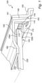
- Fig. 1 schematically shows a view of a portion of a lighting arrangement 100 according to an exemplifying embodiment of the present invention.
- the lighting arrangement 100 comprises at least one LED 110 arranged to emit light. It will be appreciated that the lighting arrangement 100 may comprise substantially any number of LEDs 110.
- the LEDs 110 are aligned in a (horizontal) array.
- the lighting arrangement 100 further comprises a PCB 120 arranged to support the LED(s) 110.
- the LEDs 110 may be provided as a LED strip comprising a flexible circuit board as carrier for the LEDs 110.
- the lighting arrangement 100 further comprises a light guide element 130 configured to guide light emitted from the LEDs 110.
- the light guide element 130 is plate-shaped and arranged in a plane, P.
- the light guide element 130 comprises a light guide 220 configured to guide light emitted from the LEDs 110, and a reflector 230 configured to reflect light emitted from the LEDs 110, wherein the light guide 220 and the reflector 230 are superimposed, i.e. arranged on top of each other.
- the LEDs 110 are arranged at an edge 140 of the light guide element 130. Hence, the LEDs 110 face the edge 140 of the light guide element 130 and are arranged in close vicinity of the edge 140.
- the lighting arrangement 100 further comprises a support structure 150 which is fastened to the PCB 120.
- the support structure 150 may be a structure or profile which has been produced by extrusion.
- the support structure 150 is arranged at a first edge portion 155 of the light guide element 130, i.e. at a first edge portion 155 of the light guide element 130 in vicinity of the edge 140 of the light guide element 130.
- the support structure 150 comprises a first portion 160 and a second portion 170.
- the first portion 160 is exemplified as a flange, which extends along the (upper) first side 180a of the light guide element 130 in the plane, P, thereof, and which, at least by a portion thereof, abuts this (upper) first side 180a of the light guide element 130.
- the second portion 160 is exemplified as a bezel or anvil, which extends along the (lower) second side 180b of the light guide element 130 in the plane, P, thereof, and which abuts this (lower) second side 180b of the light guide element 130.
- the support structure 150 further comprises a groove 190.
- the groove 190 extends substantially in a vertical direction and opens upwards at an opening 191 and ends at a bottom 192.
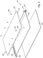
- the lighting arrangement 100 further comprises at least one spacer element 215 which is (are) arranged between the PCB 120 and the light guide element 130 for defining a minimum distance between the PCB 120 and the light guide element 130.
- the spacer element(s) 215 is (are) hereby configured to guide the forces through the light guide element 130.
- the cover plate 200 is exemplified as comprising a plurality of flanges 210.
- the flanges 210 may have the form of rectangular-shaped tabs as exemplified in Fig. 2 .
- the flanges 210 are arranged to be matingly and biasedly arranged in the groove of the support structure of the lighting arrangement 100, which is presented in more detail in Figs. 3a and 3b .
- the groove 190 of the support structure comprises at least a portion 241 of the groove 190 which is inclined with respect to the normal, N 1 , to the plane, P, and which is inclined in the direction of a normal, N 2 , to the edge 140 of the light guide element.
- the portion(s) 241 of the groove 190 hereby form(s) profile shaped as an upside-down V.
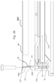
- Fig. 3c schematically shows a view in profile of the lighting arrangement shown in Fig. 3a in an exploded view, and it is referred to Fig. 3a for an increased understanding of the components and/or functioning of the lighting arrangement 100.
- the groove has a groove inner wall 193 extending between the opening 191 and a bottom 192 of the groove 190.
- the lighting arrangement further comprises the cover plate 200 arranged in parallel to the plane P.
- the cover plate comprises at least one flange 210.
- the flange has a first end 217 at its base portion 212 by which it is connected to the cover plate, and a second free end 219.
- the free end 219 of the at least one flange 210 is inserted in the groove 190 of the support structure 150 through the opening 191 of the groove 190.
- the flange 210 contacts, in the figure 3c with its free end 219, the inner wall 193 of the groove 190 at a contact location C.
- the inner wall 193 of the groove 190 extends at a (n average) groove angle ⁇ from the opening 191 to the contact location C, rendering the opening 191 of the groove 190 of being closer in horizontal direction to the light guide plate than the bottom 192 of the groove 190.
- the flange 210 extends at a (n average) angle ⁇ from its first end 217 to the contact location C.
- the indicated angles ⁇ and ⁇ are of corners that enclose the light guide plate, and for the sake of clarity are indicated with respect to plane P' which extends parallel to plane P. Because said groove angle ⁇ is somewhat larger, for example 3° or 5° or 10°, than the flange angle ⁇ , the flange(s) 210 of the cover plate 200 are matingly and biasedly arranged in the V-shaped groove 190 of the support structure 150 of the lighting arrangement 100. In the figure the groove angle ⁇ is 96°, while the flange angle ⁇ is 90°, hence the groove angle ⁇ being 6° larger than the flange angle ⁇ .
- the cover plate clamps itself onto the support structure, and extra bolts can be omitted. Consequently, the LEDs 110, which face the edge 140 of the light guide element 130, are arranged in close vicinity of the edge 140.
- the first portion 160 and the second portion 170 of the support structure 150 clamp the first edge portion 155 of the light guide element 130 for positioning of the LEDs 110 at the edge 140 of the light guide element 130.
- the plurality of fastening elements 300 fastens the cover plate 200 to the support structure 150 in order to provide the zero-tolerance and spring-loaded lighting arrangement 100.
- Fig. 4a schematically shows a view of a portion of a lighting arrangement 100 according to an exemplifying embodiment of the present invention.
- the lighting arrangement 100 comprises an (schematically indicated) optical element 550 arranged at oppositely arranged second (short) edge portions 560 of the light guide element 130, whereby only a (single) optical element 550 at the short edge portion 560 is shown in Fig. 2 for reasons of simplicity. It is further referred to Fig. 2 and the associated text for an increased understanding of the features and/or functioning of the optical element 550.
- the optical element(s) 550 e.g.
- TIR total internal refection
- the textures of the optical element(s) 550 are relatively small in respect to the thickness of the light guide.
- the profiled structure may comprise relatively sharp pyramid-formed textures, sinus-shaped textures, etc., and profiles of this kind may be produced conveniently by a laser equipment.
- the profiled structure of the optical element(s) 550 may spread the light in one direction such that the light mixing length is decreased.
- one or more of the components of the lighting arrangement 100 may have different shapes, dimensions and/or sizes than those depicted/described.
Landscapes
- Physics & Mathematics (AREA)
- General Physics & Mathematics (AREA)
- Optics & Photonics (AREA)
- Engineering & Computer Science (AREA)
- General Engineering & Computer Science (AREA)
- Microelectronics & Electronic Packaging (AREA)
- Non-Portable Lighting Devices Or Systems Thereof (AREA)
- Planar Illumination Modules (AREA)
Claims (15)
- Beleuchtungsanordnung (100), umfassend:mindestens eine Leuchtdiode, LED, (110), die zum Emittieren von Licht angeordnet ist,eine Leiterplatte, PCB, (120), die so angeordnet ist, dass sie die mindestens eine LED trägt,ein Lichtleiterelement (130), das konfiguriert ist, um von der mindestens einen LED emittiertes Licht zu leiten, wobei das Lichtleiterelement plattenförmig ist und in einer Ebene P angeordnet ist und wobei die mindestens eine LED an einem Rand (140) des Lichtleiterelements angeordnet ist,eine Trägerstruktur (150), die an der PCB befestigt und an mindestens einem ersten Randabschnitt (155) des Lichtleiterelements angeordnet ist, wobei die Trägerstruktur umfasst:- einen ersten Abschnitt (160) und einen zweiten Abschnitt (170), die so angeordnet sind, dass sie sich entlang einer ersten Seite (180a) bzw. einer zweiten Seite (180b) des Lichtleiterelements und entlang eines Abschnitts des Lichtleiterelements in der Ebene P erstrecken, wobei der erste Abschnitt und der zweite Abschnitt an der ersten Seite bzw. der zweiten Seite des Lichtleiterelements zur Anlage kommen, und- eine Nut (190) mit einer Öffnung (191) und einer Innenwand (193) undeine Abdeckplatte (200), die parallel zur Ebene P angeordnet ist und so angeordnet ist, dass sie die erste Seite des Lichtleiterelements abdeckt, wobei die Abdeckplatte mindestens einen Flansch (210) umfasst, der über ein erstes Ende (217) mit der Abdeckplatte verbunden ist,wobei der mindestens eine Flansch passend in der Nut der Trägerstruktur angeordnet ist, indem der Flansch die Innenwand der Nut an einer Kontaktstelle C berührt, wobei sich die Innenwand der Nut von der Öffnung zur Kontaktstelle C in einem Nutwinkel π erstreckt und sich der Flansch von seinem ersten Ende zur Kontaktstelle C in einem Flanschwinkel σ erstreckt,wobeider erste Abschnitt und der zweite Abschnitt den mindestens einen ersten Randabschnitt des Lichtleiterelements zur Positionierung der mindestens einen LED am Rand des Lichtleiterelements festklemmen,dadurch gekennzeichnet, dassder mindestens eine Flansch vorgespannt in der Nut der Trägerstruktur angeordnet ist und dass der Nutwinkel π 1,5° bis 20° größer ist als der Flanschwinkel σ, um den ersten Abschnitt der Trägerstruktur in Richtung des Lichtleiterelements vorzuspannen.
- Beleuchtungsanordnung nach Anspruch 1, ferner umfassend mindestens ein Abstandshalterelement (215), das zwischen der Leiterplatte und dem Lichtleiterelement angeordnet ist, um einen Mindestabstand dazwischen zu definieren.
- Beleuchtungsanordnung nach Anspruch 1 oder 2, wobei das Lichtleiterelement einen Lichtleiter (220) und einen Reflektor (230) umfasst, wobei der Lichtleiter und der Reflektor übereinander angeordnet sind.
- Beleuchtungsanordnung nach einem der vorstehenden Ansprüche, wobei mindestens ein Abschnitt (240) der Nut in Bezug auf eine Normale N1 zur Ebene P geneigt ist und in eine entgegengesetzte Richtung einer Normalen N2 zum Rand des Lichtleiterelements geneigt ist, wodurch der mindestens eine Abschnitt der Nut ein V-förmiges Profil bildet.
- Beleuchtungsanordnung nach Anspruch 4, wobei der mindestens eine Abschnitt der Nut in Bezug auf die Normale N1 zur Ebene P geneigt ist und in eine entgegengesetzte Richtung der Normalen N2 zum Rand des Lichtleiterelements in einem ersten Winkel α geneigt ist, wobei der erste Winkel α im Bereich 1,5° < α < 20° liegt.
- Beleuchtungsanordnung nach einem der vorstehenden Ansprüche, wobei die Nut in Bezug auf eine Normale N1 zur Ebene P geneigt ist und in Richtung einer Normalen N2 zum Rand des Lichtleiterelements in einem zweiten Winkel β geneigt ist, wobei der zweite Winkel β im Bereich 1,5° < β < 20° liegt.
- Beleuchtungsanordnung nach einem der vorstehenden Ansprüche, wobei mindestens ein Abschnitt (211) des mindestens einen Flansches in Bezug auf eine Normale N1 zur Ebene P geneigt ist und in eine entgegengesetzte Richtung einer Normalen N2 zum Rand des Lichtleiterelements in einem dritten Winkel γ geneigt ist, wobei der dritte Winkel γ im Bereich 1,5° < γ < 20° liegt.
- Beleuchtungsanordnung nach einem der vorstehenden Ansprüche, wobei der mindestens eine Flansch an einem peripheren Abschnitt der Abdeckplatte angeordnet ist.
- Beleuchtungsanordnung nach einem der vorstehenden Ansprüche, ferner umfassend eine Vielzahl von Befestigungselementen (300), die so angeordnet sind, dass sie die Abdeckplatte an der Trägerstruktur befestigen.
- Beleuchtungsanordnung nach Anspruch 8 und 9, wobei die Beleuchtungsanordnung eine Vielzahl von Flanschen umfasst, die durch jeweilige periphere Regionen (400) der Abdeckplatte beabstandet sind, wobei die Vielzahl von Befestigungselementen in den peripheren Regionen angeordnet ist.
- Beleuchtungsanordnung nach einem der vorstehenden Ansprüche 1 bis 8, wobei der Nutwinkel π und/oder der Flanschwinkel σ um mindestens 3° kleiner als 90° sind.
- Beleuchtungsanordnung nach Anspruch 11, wobei die Beleuchtungsanordnung frei von Befestigungselementen ist.
- Beleuchtungsanordnung nach einem der vorstehenden Ansprüche, ferner umfassend ein Diffusorelement (500), das parallel zum Lichtleiterelement angeordnet ist und konfiguriert ist, um das von der mindestens einen LED emittierte Licht zu streuen, wobei die Trägerstruktur einen dritten Abschnitt (510) umfasst, der so angeordnet ist, dass er das Diffusorelement hält.
- Beleuchtungsanordnung nach einem der vorstehenden Ansprüche, ferner umfassend ein optisches Element (550), das an mindestens einem zweiten Randabschnitt (560) des Lichtleiterelements angeordnet ist.
- Leuchte (600) zur Anordnung an einer Decke, umfassend:eine Beleuchtungsanordnung nach einem der vorstehenden Ansprüche,eine elektrische Verbindung, die mit der mindestens einen LED verbunden ist, um die mindestens eine LED mit Strom zu versorgen.
Applications Claiming Priority (2)
| Application Number | Priority Date | Filing Date | Title |
|---|---|---|---|
| EP21176341 | 2021-05-27 | ||
| PCT/EP2022/063265 WO2022248284A1 (en) | 2021-05-27 | 2022-05-17 | Lighting arrangement with light guide element |
Publications (2)
| Publication Number | Publication Date |
|---|---|
| EP4348100A1 EP4348100A1 (de) | 2024-04-10 |
| EP4348100B1 true EP4348100B1 (de) | 2025-07-09 |
Family
ID=76159395
Family Applications (1)
| Application Number | Title | Priority Date | Filing Date |
|---|---|---|---|
| EP22728944.4A Active EP4348100B1 (de) | 2021-05-27 | 2022-05-17 | Beleuchtungsanordnung mit lichtleiterelement |
Country Status (5)
| Country | Link |
|---|---|
| US (1) | US12105319B2 (de) |
| EP (1) | EP4348100B1 (de) |
| JP (1) | JP7497534B2 (de) |
| CN (1) | CN117396699A (de) |
| WO (1) | WO2022248284A1 (de) |
Family Cites Families (19)
| Publication number | Priority date | Publication date | Assignee | Title |
|---|---|---|---|---|
| US6697130B2 (en) * | 2001-01-16 | 2004-02-24 | Visteon Global Technologies, Inc. | Flexible led backlighting circuit |
| JP2009245884A (ja) * | 2008-03-31 | 2009-10-22 | Sanken Electric Co Ltd | 面光源装置 |
| KR100996403B1 (ko) * | 2010-05-14 | 2010-11-24 | 주식회사 필리스 | Led 평판조명장치 |
| JP5331143B2 (ja) * | 2011-03-01 | 2013-10-30 | 興和株式会社 | 照明装置 |
| KR101221196B1 (ko) | 2011-12-26 | 2013-01-10 | 최재훈 | 매입형 led 평판조명기구 |
| KR101185523B1 (ko) * | 2012-06-05 | 2012-09-26 | 주식회사 썬엘이디 | 일체형 도광판이 구비된 led 평판조명장치 |
| US9110216B2 (en) | 2012-11-07 | 2015-08-18 | Cooper Technologies Company | Edgelit lighting fixture and assembly |
| DE202013101770U1 (de) * | 2013-04-24 | 2014-07-28 | Zumtobel Lighting Gmbh | LED-Leuchte mit Lichtleiterplatte |
| KR102080195B1 (ko) * | 2013-07-23 | 2020-02-21 | 엘지이노텍 주식회사 | 조명장치 및 상기 조명장치를 포함하는 표시장치 |
| CN104748017A (zh) * | 2015-04-10 | 2015-07-01 | 北京京东方多媒体科技有限公司 | 背光源及显示装置 |
| CN106382520A (zh) | 2015-07-27 | 2017-02-08 | 深圳市世明伦电子有限公司 | 一种可快速更换光源组件的led面板灯 |
| CN206669360U (zh) * | 2017-03-02 | 2017-11-24 | 佛山市国星光电股份有限公司 | 一种无边框led面板灯 |
| CN206573825U (zh) * | 2017-03-30 | 2017-10-20 | 京东方科技集团股份有限公司 | 背光模组和显示装置 |
| KR101993518B1 (ko) * | 2017-06-17 | 2019-09-30 | 이승표 | Led 어레이 띠상 보드 및 그것을 갖는 엣지 led 면상 발광 조명 장치 |
| CN110741203B (zh) | 2017-06-20 | 2022-04-19 | 昕诺飞控股有限公司 | 基于光导的照明器 |
| CN207394543U (zh) | 2017-10-17 | 2018-05-22 | 海宁博华照明电器有限公司 | 面板灯 |
| DE102017011959B4 (de) * | 2017-12-22 | 2021-10-14 | Emz-Hanauer Gmbh & Co. Kgaa | Flächenleuchtmodul sowie Verfahren zu dessen Montage |
| CN110410753A (zh) * | 2019-08-01 | 2019-11-05 | 宁波港普光电科技有限公司 | 面板灯 |
| CN114383374B (zh) * | 2020-10-21 | 2025-08-01 | 博西华电器(江苏)有限公司 | 用于制冷器具的照明模块和制冷器具 |
-
2022
- 2022-05-17 US US18/564,383 patent/US12105319B2/en active Active
- 2022-05-17 JP JP2023572675A patent/JP7497534B2/ja active Active
- 2022-05-17 WO PCT/EP2022/063265 patent/WO2022248284A1/en not_active Ceased
- 2022-05-17 CN CN202280038176.9A patent/CN117396699A/zh active Pending
- 2022-05-17 EP EP22728944.4A patent/EP4348100B1/de active Active
Also Published As
| Publication number | Publication date |
|---|---|
| EP4348100A1 (de) | 2024-04-10 |
| US20240210613A1 (en) | 2024-06-27 |
| WO2022248284A1 (en) | 2022-12-01 |
| JP7497534B2 (ja) | 2024-06-10 |
| CN117396699A (zh) | 2024-01-12 |
| JP2024518652A (ja) | 2024-05-01 |
| US12105319B2 (en) | 2024-10-01 |
Similar Documents
| Publication | Publication Date | Title |
|---|---|---|
| US8764264B2 (en) | Edge-lit luminaire | |
| JP6049248B2 (ja) | 照明装置 | |
| EP2917633B1 (de) | Kantenbeleuchteter leuchtkörper | |
| EP2648024B1 (de) | Leuchtmodul und Leuchte mit selbigem | |
| US10215911B2 (en) | Lighting assembly | |
| JP4365453B2 (ja) | 机上照明装置 | |
| CN112219061A (zh) | 带有声音抑制的悬挂式垂饰光导灯具 | |
| US8789993B2 (en) | Light-emitting device | |
| CN104456189A (zh) | 照明装置 | |
| US10539737B2 (en) | Lighting fixture with end plate slots and elongated heat sinks for retaining an edge-lit optical device | |
| JP2017507466A (ja) | 後付け照明アセンブリ | |
| CN203949004U (zh) | 照明装置 | |
| JP2013182730A (ja) | 照明モジュールおよびそれを備えた照明装置 | |
| CN106716010A (zh) | Led照明设备 | |
| EP4348100B1 (de) | Beleuchtungsanordnung mit lichtleiterelement | |
| HK1217225A1 (zh) | 照明装置 | |
| CN104508366A (zh) | Led照明装置 | |
| EP1625326A1 (de) | Dünnes, flaches lampenmodul für die beleuchtung von regalen | |
| CN206626458U (zh) | 灯具及照明系统 | |
| WO2018000836A1 (zh) | 光源组件、背光装置和显示装置 | |
| CN110573793B (zh) | 组装灯具的套件和方法 | |
| JP2011054351A (ja) | 照明装置 | |
| WO2012157145A1 (ja) | 照明装置 | |
| KR20200028739A (ko) | 초슬림 백라이트 유닛 | |
| EP3244124A1 (de) | Leuchte und flächenabdeckungsanordnung |
Legal Events
| Date | Code | Title | Description |
|---|---|---|---|
| STAA | Information on the status of an ep patent application or granted ep patent |
Free format text: STATUS: UNKNOWN |
|
| STAA | Information on the status of an ep patent application or granted ep patent |
Free format text: STATUS: THE INTERNATIONAL PUBLICATION HAS BEEN MADE |
|
| PUAI | Public reference made under article 153(3) epc to a published international application that has entered the european phase |
Free format text: ORIGINAL CODE: 0009012 |
|
| STAA | Information on the status of an ep patent application or granted ep patent |
Free format text: STATUS: REQUEST FOR EXAMINATION WAS MADE |
|
| 17P | Request for examination filed |
Effective date: 20240102 |
|
| AK | Designated contracting states |
Kind code of ref document: A1 Designated state(s): AL AT BE BG CH CY CZ DE DK EE ES FI FR GB GR HR HU IE IS IT LI LT LU LV MC MK MT NL NO PL PT RO RS SE SI SK SM TR |
|
| DAV | Request for validation of the european patent (deleted) | ||
| DAX | Request for extension of the european patent (deleted) | ||
| GRAP | Despatch of communication of intention to grant a patent |
Free format text: ORIGINAL CODE: EPIDOSNIGR1 |
|
| STAA | Information on the status of an ep patent application or granted ep patent |
Free format text: STATUS: GRANT OF PATENT IS INTENDED |
|
| INTG | Intention to grant announced |
Effective date: 20250114 |
|
| GRAS | Grant fee paid |
Free format text: ORIGINAL CODE: EPIDOSNIGR3 |
|
| P01 | Opt-out of the competence of the unified patent court (upc) registered |
Free format text: CASE NUMBER: APP_17779/2025 Effective date: 20250411 |
|
| GRAA | (expected) grant |
Free format text: ORIGINAL CODE: 0009210 |
|
| STAA | Information on the status of an ep patent application or granted ep patent |
Free format text: STATUS: THE PATENT HAS BEEN GRANTED |
|
| AK | Designated contracting states |
Kind code of ref document: B1 Designated state(s): AL AT BE BG CH CY CZ DE DK EE ES FI FR GB GR HR HU IE IS IT LI LT LU LV MC MK MT NL NO PL PT RO RS SE SI SK SM TR |
|
| REG | Reference to a national code |
Ref country code: GB Ref legal event code: FG4D |
|
| REG | Reference to a national code |
Ref country code: CH Ref legal event code: EP |
|
| REG | Reference to a national code |
Ref country code: IE Ref legal event code: FG4D |
|
| REG | Reference to a national code |
Ref country code: DE Ref legal event code: R096 Ref document number: 602022017336 Country of ref document: DE |
|
| REG | Reference to a national code |
Ref country code: NL Ref legal event code: MP Effective date: 20250709 |
|
| PG25 | Lapsed in a contracting state [announced via postgrant information from national office to epo] |
Ref country code: PT Free format text: LAPSE BECAUSE OF FAILURE TO SUBMIT A TRANSLATION OF THE DESCRIPTION OR TO PAY THE FEE WITHIN THE PRESCRIBED TIME-LIMIT Effective date: 20251110 |
|
| PG25 | Lapsed in a contracting state [announced via postgrant information from national office to epo] |
Ref country code: NL Free format text: LAPSE BECAUSE OF FAILURE TO SUBMIT A TRANSLATION OF THE DESCRIPTION OR TO PAY THE FEE WITHIN THE PRESCRIBED TIME-LIMIT Effective date: 20250709 |
|
| REG | Reference to a national code |
Ref country code: AT Ref legal event code: MK05 Ref document number: 1812094 Country of ref document: AT Kind code of ref document: T Effective date: 20250709 |
|
| PG25 | Lapsed in a contracting state [announced via postgrant information from national office to epo] |
Ref country code: IS Free format text: LAPSE BECAUSE OF FAILURE TO SUBMIT A TRANSLATION OF THE DESCRIPTION OR TO PAY THE FEE WITHIN THE PRESCRIBED TIME-LIMIT Effective date: 20251109 |
|
| PG25 | Lapsed in a contracting state [announced via postgrant information from national office to epo] |
Ref country code: NO Free format text: LAPSE BECAUSE OF FAILURE TO SUBMIT A TRANSLATION OF THE DESCRIPTION OR TO PAY THE FEE WITHIN THE PRESCRIBED TIME-LIMIT Effective date: 20251009 |
|
| REG | Reference to a national code |
Ref country code: LT Ref legal event code: MG9D |
|
| PG25 | Lapsed in a contracting state [announced via postgrant information from national office to epo] |
Ref country code: AT Free format text: LAPSE BECAUSE OF FAILURE TO SUBMIT A TRANSLATION OF THE DESCRIPTION OR TO PAY THE FEE WITHIN THE PRESCRIBED TIME-LIMIT Effective date: 20250709 |
|
| PG25 | Lapsed in a contracting state [announced via postgrant information from national office to epo] |
Ref country code: FI Free format text: LAPSE BECAUSE OF FAILURE TO SUBMIT A TRANSLATION OF THE DESCRIPTION OR TO PAY THE FEE WITHIN THE PRESCRIBED TIME-LIMIT Effective date: 20250709 |
|
| PG25 | Lapsed in a contracting state [announced via postgrant information from national office to epo] |
Ref country code: HR Free format text: LAPSE BECAUSE OF FAILURE TO SUBMIT A TRANSLATION OF THE DESCRIPTION OR TO PAY THE FEE WITHIN THE PRESCRIBED TIME-LIMIT Effective date: 20250709 |
|
| PG25 | Lapsed in a contracting state [announced via postgrant information from national office to epo] |
Ref country code: GR Free format text: LAPSE BECAUSE OF FAILURE TO SUBMIT A TRANSLATION OF THE DESCRIPTION OR TO PAY THE FEE WITHIN THE PRESCRIBED TIME-LIMIT Effective date: 20251010 |
|
| PG25 | Lapsed in a contracting state [announced via postgrant information from national office to epo] |
Ref country code: SE Free format text: LAPSE BECAUSE OF FAILURE TO SUBMIT A TRANSLATION OF THE DESCRIPTION OR TO PAY THE FEE WITHIN THE PRESCRIBED TIME-LIMIT Effective date: 20250709 |
|
| PG25 | Lapsed in a contracting state [announced via postgrant information from national office to epo] |
Ref country code: LV Free format text: LAPSE BECAUSE OF FAILURE TO SUBMIT A TRANSLATION OF THE DESCRIPTION OR TO PAY THE FEE WITHIN THE PRESCRIBED TIME-LIMIT Effective date: 20250709 |
|
| PG25 | Lapsed in a contracting state [announced via postgrant information from national office to epo] |
Ref country code: PL Free format text: LAPSE BECAUSE OF FAILURE TO SUBMIT A TRANSLATION OF THE DESCRIPTION OR TO PAY THE FEE WITHIN THE PRESCRIBED TIME-LIMIT Effective date: 20250709 Ref country code: BG Free format text: LAPSE BECAUSE OF FAILURE TO SUBMIT A TRANSLATION OF THE DESCRIPTION OR TO PAY THE FEE WITHIN THE PRESCRIBED TIME-LIMIT Effective date: 20250709 |
|
| PG25 | Lapsed in a contracting state [announced via postgrant information from national office to epo] |
Ref country code: RS Free format text: LAPSE BECAUSE OF FAILURE TO SUBMIT A TRANSLATION OF THE DESCRIPTION OR TO PAY THE FEE WITHIN THE PRESCRIBED TIME-LIMIT Effective date: 20251009 |
|
| PG25 | Lapsed in a contracting state [announced via postgrant information from national office to epo] |
Ref country code: ES Free format text: LAPSE BECAUSE OF FAILURE TO SUBMIT A TRANSLATION OF THE DESCRIPTION OR TO PAY THE FEE WITHIN THE PRESCRIBED TIME-LIMIT Effective date: 20250709 |