EP4347485B1 - System zur evakuierung von nox-gasen aus einem salpetersäurevorratsbehälter - Google Patents
System zur evakuierung von nox-gasen aus einem salpetersäurevorratsbehälter Download PDFInfo
- Publication number
- EP4347485B1 EP4347485B1 EP22730282.5A EP22730282A EP4347485B1 EP 4347485 B1 EP4347485 B1 EP 4347485B1 EP 22730282 A EP22730282 A EP 22730282A EP 4347485 B1 EP4347485 B1 EP 4347485B1
- Authority
- EP
- European Patent Office
- Prior art keywords
- gas
- nitric acid
- tail gas
- ejector
- tail
- Prior art date
- Legal status (The legal status is an assumption and is not a legal conclusion. Google has not performed a legal analysis and makes no representation as to the accuracy of the status listed.)
- Active
Links
Images


Classifications
-
- C—CHEMISTRY; METALLURGY
- C01—INORGANIC CHEMISTRY
- C01B—NON-METALLIC ELEMENTS; COMPOUNDS THEREOF; METALLOIDS OR COMPOUNDS THEREOF NOT COVERED BY SUBCLASS C01C
- C01B21/00—Nitrogen; Compounds thereof
- C01B21/20—Nitrogen oxides; Oxyacids of nitrogen; Salts thereof
- C01B21/24—Nitric oxide (NO)
- C01B21/26—Preparation by catalytic or non-catalytic oxidation of ammonia
-
- C—CHEMISTRY; METALLURGY
- C01—INORGANIC CHEMISTRY
- C01B—NON-METALLIC ELEMENTS; COMPOUNDS THEREOF; METALLOIDS OR COMPOUNDS THEREOF NOT COVERED BY SUBCLASS C01C
- C01B21/00—Nitrogen; Compounds thereof
- C01B21/20—Nitrogen oxides; Oxyacids of nitrogen; Salts thereof
- C01B21/38—Nitric acid
- C01B21/46—Purification; Separation ; Stabilisation
-
- B—PERFORMING OPERATIONS; TRANSPORTING
- B01—PHYSICAL OR CHEMICAL PROCESSES OR APPARATUS IN GENERAL
- B01D—SEPARATION
- B01D19/00—Degasification of liquids
- B01D19/0036—Flash degasification
-
- C—CHEMISTRY; METALLURGY
- C01—INORGANIC CHEMISTRY
- C01B—NON-METALLIC ELEMENTS; COMPOUNDS THEREOF; METALLOIDS OR COMPOUNDS THEREOF NOT COVERED BY SUBCLASS C01C
- C01B21/00—Nitrogen; Compounds thereof
- C01B21/20—Nitrogen oxides; Oxyacids of nitrogen; Salts thereof
- C01B21/24—Nitric oxide (NO)
- C01B21/26—Preparation by catalytic or non-catalytic oxidation of ammonia
- C01B21/28—Apparatus
-
- C—CHEMISTRY; METALLURGY
- C01—INORGANIC CHEMISTRY
- C01B—NON-METALLIC ELEMENTS; COMPOUNDS THEREOF; METALLOIDS OR COMPOUNDS THEREOF NOT COVERED BY SUBCLASS C01C
- C01B21/00—Nitrogen; Compounds thereof
- C01B21/20—Nitrogen oxides; Oxyacids of nitrogen; Salts thereof
- C01B21/38—Nitric acid
Definitions
- the current application concerns a system for evacuating NO x gases from a nitric acid storage tank released therein, in a production plant for producing nitric acid or in a storage area for nitric acid, as well as to a method for operating such a system.
- nitric acid is a clear, colorless liquid with a strong odor.
- Nitric acid is produced in large quantities principally by catalytic oxidation of ammonia (Ostwald process). Ammonia is converted to nitric acid in two stages. The ammonia is first oxidized in an ammonia burner on platinum gauzes (commonly called ammonia convertor), producing nitric oxide (nitrogen monoxide) and water: 4 NH 3 (g) +5 O 2 (g) ⁇ 4 NO (g) + 6 H 2 O (g) (1)
- reaction product from (1) nitric oxide (in this disclosure also called nitrogen monoxide (NO)), following cooling, is then oxidized to nitrogen dioxide (NO 2 ) and further to dinitrogen tetroxide N 2 O 4 (g) in an oxidation section: 2 NO (g) + O 2 (g) ⁇ 2 NO 2 (g) (2) 2 NO 2 (g) ⁇ N 2 O 4 (g) (3)
- NO nitrogen monoxide
- Cooling of nitrogen oxide gases is accomplished through heat transfer, firstly in waste heat boiler, then a process gas cooler in which condensed nitric acid is separated from nitric oxide, nitrogen dioxide and dinitrogen tetroxide and nitric acid gases, collectively called NO x gases, and also by heating in the heater of the tail gas released at the outlet of the absorption tower in which the NO x gases are absorbed.
- nitric acid which is up to 68 % (azeotrope) is obtained.
- concentration of nitric acid can be increased up to 99 % concentrated nitric acid.
- the total reaction is given by the following formula: NH 3 + 2 O 2 ⁇ HNO 3 + H 2 O (6)
- the main process units in a nitric acid production plant include an ammonia converter (conversion of ammonia into nitric oxides using oxygen over a suitable catalyst), an oxidation section (conversion of nitric oxide into nitrogen dioxide and nitrogen tetroxide), an absorber unit (for the absorption of NO x gases into water) and a bleacher unit (removal of unreacted dissolved gases, containing in particular NO x and gases, from the aqueous nitric acid solution, which give it its typical brownish color).
- ammonia converter conversion of ammonia into nitric oxides using oxygen over a suitable catalyst
- an oxidation section conversion of nitric oxide into nitrogen dioxide and nitrogen tetroxide
- an absorber unit for the absorption of NO x gases into water
- a bleacher unit removal of unreacted dissolved gases, containing in particular NO x and gases, from the aqueous nitric acid solution, which give it its typical brownish color.
- the process for the production of nitric acid can be differentiated into a mono-pressure (single-pressure) and dual pressure (split-pressure) process.
- a mono-pressure process the converter and the absorber unit operate at roughly the same working pressure.
- Such mono-pressure process generally includes low-pressure (2 to 6 bar) and high-pressure (6 to 16 bar, in particular 9 to 16 bar) processes.
- the absorber unit operates at a higher working pressure than the ammonia converter.
- Modern dual pressure processes feature a low-pressure (LP) ammonia converter operating typically at 2 to 6 bar, and a high-pressure (HP) absorber unit operating at 9 to 16 bar.
- LP low-pressure
- HP high-pressure
- a dual pressure process requires an air compressor to feed low-pressure air to the converter, and a NO x gas compressor to feed high-pressure NO x gases to the absorber unit.
- the working pressure of an air compressor is from 2 to 6 bar, inclusive, and the working pressure of a NO x gas compressor is from 9 to 16 bar, inclusive.
- a dual-pressure plant comprises a NO x gas compressor, a mono-pressure plant does not.
- a dual pressure plant and process works as follows.
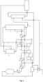
- Ammonia 32 optionally pre-heated in a pre-heater unit 33 is mixed with compressed air 34 pressurised to a low pressure using an air compressor 36 operable at a low gas pressure, in a mixing apparatus 35, and the resulting ammonia/air mixture 14 is fed to an ammonia convertor 37, operating at a low pressure, where ammonia is oxidized over a suitable catalyst, thus obtaining a LP NO x gas/steam mixture 15, comprising water and NO.
- the heat of the mixture coming out of the ammonia convertor is recovered, after which the NO x gas/stream mixture is subsequently cooled down in a water cooler/condenser 38 to temperature where the water condenses, and an aqueous diluted nitric acid mixture 17 is separated from a gaseous NO x stream 18.
- the LP gaseous NO x stream is further oxidized to further convert the NO to NO 2 and N 2 O 4 , and cooled down again in a cooler/separator 39 to separate out an aqueous diluted nitric acid mixture 21 which is directed to an absorption tower 41, commonly called absorption tower.
- the gaseous NO x stream 22 is sent to a NO x gas compressor 40 wherein its pressure is elevated from a low pressure to a high pressure, being about equal to the absorber unit operating pressure, and the pressurized gaseous NO x stream 24 is sent to the absorber unit 41 too.
- the HP NO x gas reacts with water to produce the tail gas 5 and a stream of raw nitric acid also containing residual NO x gas 27, which is fed to a bleacher 42 over a valve 31.
- the residual NO x gas is then stripped out with a gaseous medium 16 such as an oxygen-containing gas or air, inside the bleacher unit 42, operating at low pressure; the bleacher unit is generally operated at about the same pressure as the ammonia convertor.
- the NO x -loaded stripping gas 19 is directed to the oxidation section, upstream of the NO x gas compressor 40.
- the stripped nitric acid stream 29 from the bleacher unit 42 is then sent to storage for further processing.
- the drive power for both air compressor 36 and NO x gas compressor 40 originates from a tail gas expander 7 and a steam turbine or electric motor (not shown).
- the heat from the gaseous NO x stream 24 is optionally used for heating the tail gas 5 in the tail gas heater 43, the tail gas heater being therefore optionally present.
- the acid needs to be stored in a suitable storage tank, in particular in a tank which is made of a material with a low corrosion velocity when containing the nitric acid.
- a suitable storage tank in particular in a tank which is made of a material with a low corrosion velocity when containing the nitric acid.
- Conventional materials for nitric acid storage tanks are stainless steel or alloys-containing stainless steel. As complete bleaching of the nitric acid solution prior to its storage is, in practice, never achieved, this means that there remains unreacted dissolved NO x gases in the stored nitric acid, which in turn implies the equilibrium of those NO x gases between the solution and the gas phase above the solution in the storage tank.
- a first air aeration pipe and a first tail gas aeration pipe are introduced below the liquid level in the first water-sealed tank and the installation height of the first air aeration pipe is lower than that of the first tail gas aeration pipe.
- the model also comprises an industrial water supply mechanism and a compressed air source.
- the utility model CN205627538 U also describes a nitric acid tail gas absorbing device.
- the device is connected to a negative pressure pump.
- the connection to a negative pressure pump is further connected to a water sprayer pipe through one end of the negative pressure pump and the other end of the negative tube inserts in the nitric acid storage tank.
- the invention concerns a system for evacuating NO x gases from a nitric acid storage tank released therein, in a production plant for producing nitric acid or in a storage area for nitric acid, as well as to a method for operating such a system, using a gas ejector device.
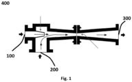
- a gas ejector 400 device comprises a first inlet for a high-pressure gas 100, called the motive gas, and a second inlet for a low-pressure gas 200 that is to be drawn into the device where it is mixed with the motive gas.
- the resulting gas mixture is expelled at the outlet 300 at a pressure between the high-pressure of the motive gas and the low-pressure of the inlet gas.
- the expelled gas can be expelled into the open air, or can be transported through a conduit to a further location downstream the gas ejector device.
- such a gas ejector device can be used advantageously to evacuate gases from a liquid storage tank, in particular the NO x gases from a nitric acid storage tank, in a nitric acid production plant or in a storage area for nitric acid, by using the tail gas generated in an absorption column, or an NO x -containing gas upstream the absorption tower, as the motive gas to drive the gas ejector to draw the NO x gases out of a nitric acid storage tank, and to evacuate these NO x gases as well as the NO x -containing tail gas.
- the use of such ejector device allows for abating the NO x gases from a nitric storage tank using a small area footprint and at lower costs than with a conventional scrubber device.
- a gas inlet that is "branched from” means that the inlet only receives the gas from the conduit to which it is branched from, divided from or split from.
- a system for evacuating NO x gases from a nitric acid storage tank in a nitric acid production plant is disclosed.
- the system is characterized in that the nitric acid production plant comprises a gas ejector comprising at least two gas inlets and at least one gas outlet, wherein:
- the inventors have now established that this is possible to use a gas ejector to evacuate the NO x gases from a storage tank containing nitric acid.
- gases at a pressure of at least 2 bar in the nitric acid process suitable for use as a motive gas and the gases from the storage tank are at atmospheric pressure, it is possible to use a gas ejector in combination with these two types of gases.
- the result is that the gases of the storage tank are evacuated and, instead of spreading in the surroundings of the storage tank, they are diluted, hence treated, through dilution using the tail gas, at the outlet of the gas ejector.
- the system of the disclosure when compared to the systems of the prior art, is simplified, has a smaller area footprint and is cheaper.
- the person skilled in the art will understand that what is required in the system of the disclosure is the presence of a gas that can act as a motive gas in a gas ejector and of an acid storage tank in which gases at a low pressure are released.
- the pressure should be lower than the pressure of the motive gas, such that a pressure drop is created, resulting in under-pressure in the storage tank, in turn resulting in the proper functioning of the gas ejector, meaning that the NO x gases released in the storage tank are evacuated out of the storage tank, and to a safe location.
- the system of the disclosure can be to the system of any process comprising a gas that can be used as a motive gas and low pressure gases in a storage tank that are to be evacuated.
- a system for evacuating NO x gases from the nitric acid storage tank 2 in a nitric acid production plant is disclosed.
- the system is characterized in that the nitric acid production plant comprises the gas ejector 10 comprising at least two gas inlets and at least one gas outlet, wherein:
- the inventors have now established that this is possible to use a gas ejector 10 to evacuate the NO x gases from a storage tank 2 containing nitric acid.
- gases at a pressure of at least 2 bar in the nitric acid process suitable for use as a motive gas and the gases from the storage tank 2 are at atmospheric pressure it is possible to use the gas ejector 10 in combination with these two types of gases.
- the result is that the gases of the storage tank 2 are evacuated and, instead of spreading in the surroundings of the storage tank 2, they are diluted, hence handled, through dilution using the tail gas, at the outlet of the gas ejector.
- the first gas inlet of the gas ejector is branched from a gas conduit downstream from an absorption tower having an outlet from which a NOx-containing tail gas is obtained, through which the tail gas is flowing, and the gas outlet of the gas ejector is fluidically connected to a gas conduit downstream from a tail gas expander for expanding the tail gas and/or downstream from a tail gas heater for heating the tail gas to a temperature ranging from 200 to 650°C, thereby generating a heated tail gas.
- a tail gas heater is a system which comprises one or more, such as one to four, heaters installed in series, for gradually heating the tail gas from a temperature ranging from 2 °C to 50°C, to a temperature ranging from 200 °C to 650 °C, thereby generated a heated tail gas.
- the first gas inlet 11 of the gas ejector 10 is branched from the gas conduit downstream from the absorption tower 41 having the outlet 6 from which the NO x -containing tail gas 5 is obtained, through which the tail gas 5 is flowing, and the gas outlet 13 of the gas ejector 10 is fluidically connected to the gas conduit downstream from the tail gas expander 7 for expanding the tail gas 5 and/or downstream from the tail gas heater 43 for heating the tail gas 5 to a temperature ranging from 200 to 650°C, thereby generating the heated tail gas 49.
- the tail gas heater 43 is a system which comprises one or more, such as one to four, heaters installed in series, for gradually heating the tail gas from a temperature ranging from 2 °C to 50 °C, to a temperature ranging from 200 °C to 650 °C, thereby generating the heated tail gas 49.
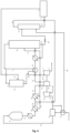
- the first gas inlet of the gas ejector is branched from a gas conduit downstream from a tail gas heater for heating a NO x -containing tail gas obtained from an outlet of an absorption tower to a temperature ranging from 200 to 650 °C, thereby generating a heated tail gas, and the gas outlet of the gas ejector is fluidically connected to a gas conduit downstream from a tail gas expander for expanding the heated tail gas.
- a tail gas heater is a system which comprises one or more, such as one to four, heaters installed in series, for gradually heating the tail gas from a temperature ranging from 2 °C to 50 °C, to a temperature ranging from 200 °C to 650 °C, thereby generating a heated tail gas.
- the tail gas heater comprises one or more heaters in series, it is possible to have the first inlet of the tail gas ejector downstream a first heater of the tail gas heater, and the outlet of the gas ejector is in fluid communication with the outlet of a second heater of the tail gas heater, as long as the second heater is located downstream the first heater - that is as long as there is the necessary pressure drop between the gas conduit in fluid communication with the first inlet of the gas ejector and the gas conduit in fluid communication with the outlet of the gas ejector.
- the first gas inlet 11 of the gas ejector 10 is branched from the gas conduit downstream from the tail gas heater 43 for heating the NO x -containing tail gas 5 obtained from the outlet of the absorption tower 41 to a temperature ranging from 200 to 650°C, thereby generating the heated tail 49, and the gas outlet 13 of the gas ejector 10 is fluidically connected to the gas conduit downstream from the tail gas expander 7 for expanding the heated tail gas (49).
- the tail gas heater 43 is a system which comprises one or more, such as one to four, heaters installed in series, for gradually heating the tail gas from a temperature ranging from 2 °C to 50 °C, to a temperature ranging from 200 °C to 650 °C, thereby generating the heated tail gas 49.
- the tail gas heater 43 comprises one or more heaters in series, it is possible to have the first inlet 11 of the tail gas ejector 10 downstream a first heater of the tail gas heater 43, and the outlet 13 of the ejector 10 is in fluid communication with the outlet of a second heater of the tail gas heater 43, as long as the second heater is located downstream the first heater - that is as long as there is the necessary pressure drop between the gas conduit in fluid communication with the first inlet 11 of the ejector 10 and the gas conduit in fluid communication with the outlet 13 of the ejector 10.
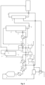
- the first gas inlet of the gas ejector is branched from a gas conduit downstream from a NO x gas compressor and upstream from an absorption tower, and the gas outlet of the gas ejector is fluidically connected to a gas conduit upstream from the NO x gas compressor.
- the first gas inlet 11 of the gas ejector 10 is branched from the gas conduit downstream from the NO x gas compressor 40 and upstream from the absorption tower 41, and the gas outlet 13 of the gas ejector 10 is fluidically connected to a gas conduit upstream from the NO x gas compressor 40.
- the pressure P1 ranges from 4 bar to 16 bar.
- the pressure P1 ranges from 4 bar to 16 bar.
- the system further comprises a tail gas treatment unit located downstream from an absorption tower and/or downstream from a tail gas expander.
- tail gas treatment unit allows for a reduction of the emissions downstream the tail gas expander. Indeed, the lower the concentration on NO x gases at the tail gas expander inlet or downstream the tail gas expander outlet, and upstream the location of the release of the gases to the atmosphere, the lower the concentration in NO x gases of the gases that are released to the atmosphere. Therefore, the use of a tail gas treatment unit results in enhanced control of the emissions from the nitric acid production plant.
- the system further comprises a tail gas treatment unit (not shown) located downstream from the absorption tower (41) and/or downstream from the tail gas expander (7).
- tail gas treatment unit (not shown) allows for a reduction of the emissions downstream the tail gas expander 7. Indeed, the lower the concentration on NO x gases at the tail gas expander inlet 8 or downstream the tail gas expander outlet 9, and upstream the location of the release of the gases to the atmosphere, the lower the concentration in NO x gases of the gases that are released to the atmosphere. Therefore, the use of a tail gas treatment unit results in enhanced control of the emissions from the nitric acid production plant.
- a method for evacuating NO x gases from a nitric acid storage tank in a nitric acid production plant wherein a first NO x -containing gas from a gas conduit of the nitric acid production plant a at a pressure P1 ranging from 2 bar to 16 bar and a second NO x -containing gas from the nitric acid storage tank at atmospheric pressure are respectively flown in through a first inlet and a second inlet of a gas ejector and flown out to a gas conduit of the nitric production plant through which a NO x -containing gas is flowing at a pressure P2 which is lower than P1, is disclosed.
- the inventors have now established that this is possible to use a gas ejector to evacuate the NO x gases from a storage tank of a nitric acid.
- gases at a pressure of at least 2 bar in the nitric acid process suitable for use as a motive gas and the gases from the storage tank are at atmospheric pressure, it is possible to use a gas ejector in combination with these two types of gases.
- the result is that the gases of the storage tank are evacuated and, instead of spreading in the surroundings of the storage tank, they are diluted, hence handled, through dilution using the tail gas, at the outlet of the gas ejector.
- the gases of the storage tank evacuated are also handled in a manner that does not involve the washing of the NO x gases with water, as is commonly done, for example through the use of scrubbing systems. Therefore, the method of the disclosure, when compared to the methods of the prior art, is simplified and cheaper, due to the simple and cheap operation of the gas ejector.
- a tail gas that can act as a motive gas in a gas ejector and of an acid storage tank in which gases at a low pressure are released.
- the pressure should be lower than the pressure of the motive gas, such that a pressure drop is created, resulting in under-pressure in the storage tank, in turn resulting in the proper functioning of the gas ejector, meaning that the gases released in the storage tank are actually directed out of the storage tank, and at a safe location.
- the system of the disclosure can be applied to any process comprising a gas that can be used as a motive gas and low pressure gases in a storage tank that are to be evacuated.
- a method for evacuating NO x gases from the nitric acid storage tank 2 in a nitric acid production plant wherein a first NO x -containing gas from a gas conduit of the nitric acid production plant a at a pressure P1 ranging from 2 bar to 16 bar and a second NO x -containing gas from the nitric acid storage tank 2 at atmospheric pressure are respectively flown in through the inlets 11 and 12 of the gas ejector 10 and flown out to a gas conduit of the nitric production plant through which a NO x -containing gas is flowing at a pressure P2 which is lower than P1, is disclosed.
- the inventors have now established that this is possible to use a gas ejector 10 to evacuate the NO x gases from a storage tank 2 containing nitric acid.
- gases at a pressure of at least 2 bar in the nitric acid process suitable for use as a motive gas and the gases from the storage tank 2 are at atmospheric pressure it is possible to use the gas ejector 10 in combination with these two types of gases.
- the result is that the gases of the storage tank 2 are evacuated and, instead of spreading in the surroundings of the storage tank 2, they are diluted, hence handled, through dilution using the tail gas, at the outlet of the gas ejector.
- the first NO x -containing gas is a tail gas obtained from an outlet of an absorption tower and the outflowing gas stream of the gas ejector flows to a gas conduit downstream from a tail gas expander for expanding the tail gas and/or downstream from a tail gas heater for heating the tail gas to a temperature ranging from 200 to 650°C, thereby generating a heated tail gas.
- the first NO x -containing gas is the tail gas (5) obtained from the outlet (6) of the absorption tower (41) and the outflowing gas stream of the gas ejector (10) flows to the gas conduit downstream from the tail gas expander (7) for expanding the tail gas (5) and/or downstream from the tail gas heater (43) for heating the tail gas (5) to a temperature ranging from 200 to 650°C, thereby generating the heated tail gas (49).
- the first NO x -containing gas is obtained from a gas conduit downstream from a tail gas heater for heating a tail gas obtained from an outlet of an absorption tower to a temperature ranging from 200 to 650°C, thereby generating a heated tail gas, and the outflowing gas stream of the gas ejector flows to a gas conduit downstream from a tail gas expander for expanding the heated tail gas.
- the tail gas heater comprises one or more heaters in series, it is possible to have the first inlet of the tail gas ejector downstream a first heater of the tail gas heater, and the outlet of the gas ejector is in fluid communication with the outlet of a second heater of the tail gas heater, as long as the second heater is located downstream the first heater - that is as long as there is the necessary pressure drop between the gas conduit in fluid communication with the first inlet of the gas ejector and the gas conduit in fluid communication with the outlet of the gas ejector.
- the first NO x -containing gas is obtained from the gas conduit downstream from a tail gas heater 43 for heating the tail gas 5 obtained from the outlet 6 of the absorption tower 41 to a temperature ranging from 200 to 650°C, thereby generating the heated tail gas 49, and the outflowing gas stream of the gas ejector (10) flows to a gas conduit downstream from a tail gas expander (7) for expanding the heated tail gas (49).
- the tail gas heater 43 comprises one or more heaters in series, it is possible to have the first inlet 11 of the tail gas ejector 10 downstream a first heater of the tail gas heater 43, and the outlet 13 of the gas ejector 10 is in fluid communication with the outlet of a second heater of the tail gas heater 43, as long as the second heater is located downstream the first heater - that is as long as there is the necessary pressure drop between the gas conduit in fluid communication with the first inlet 11 of the gas ejector 10 and the gas conduit in fluid communication with the outlet 13 of the gas ejector 10.
- the first NO x -containing gas is obtained from a gas conduit downstream from a NO x gas compressor and upstream from an absorption tower, and the outflowing gas stream of the gas ejector flows to a gas conduit upstream from the NO x gas compressor.
- the first NO x -containing gas is obtained from the gas conduit downstream from the tail gas heater 43 for heating the tail gas 5 obtained from the outlet 6 of the absorption tower 41 to a temperature ranging from 200 to 650°C, thereby generating the heated tail gas 49, and the outflowing gas stream of the gas ejector 10 flows to the gas conduit downstream from a tail gas expander 7 for expanding the heated tail gas 49.
- the pressure P1 ranges from 4 bar to 16 bar.
- the pressure P1 ranges from 4 bar to 16 bar.
- the method further comprises the step of treating a tail gas downstream from an absorption tower and/or downstream from a tail gas expander.
- Such treatment of the tail gas allows for a reduction of the emissions downstream the tail gas expander.
- the lower the concentration on NO x gases at the tail gas inlet or downstream the tail gas outlet and upstream the location of the release of the gases to the atmosphere the lower the concentration in NO x gases of the gases leaving the gas ejector is.
- the lower the concentration on NO x gases in the tail gas is, the lower the concentration in NO x gases that are released to the atmosphere. Therefore, the treatment of the tail gas results in enhanced control of the emissions from the nitric acid production plant.
- the method further comprises the step of treating the tail gas 5 downstream from the absorption tower 41 and/or downstream from the tail gas expander 7.
- Such treatment of the tail gas allows for a reduction of the emissions downstream the tail gas expander 7. Indeed, the lower the concentration on NO x gases at the tail gas expander inlet 8 or downstream the tail gas expander outlet 9, and upstream the location of the release of the gases to the atmosphere, the lower the concentration in NO x gases of the gases that are released to the atmosphere. Therefore, the use of a tail gas treatment unit results in enhanced control of the emissions from the nitric acid production plant.
- the method is a periodical or continuous process.
- a method for revamping a nitric acid production plant comprising the step of installing a gas ejector for executing the method of the disclosure, is disclosed.
- a gas ejector for evacuating NO x gases from a nitric acid storage tank, in a production plant for producing nitric acid, is disclosed.
- the NO x gas 22 was compressed in the NO x gas compressor 40, thereby generating the compressed NO x gas 24 at a pressure of 11 bar.
- the compressed NO x gas 24 was absorbed in the absorption tower 41, thereby generating the tail gas 5 having a pressure ranging of 10 bar and a stream of raw nitric acid 27 that was treated in the bleacher 42 out of which nitric acid was sent to the storage tank 2.
- the tail gas 5 was heated in the tail gas heater 43, thereby generating a heated tail gas having a temperature of 450 °C and a pressure of 9.5 bar at the tail gas heater outlet.
- the pressure at the nitric acid storage tank outlet 3 equaled atmospheric pressure.
- the NO x gases from the nitric acid storage tank 2 were directed, through the storage tank outlet 3, to the second inlet 12 of the gas ejector 10.
- the gases directed to both inlets 11 and 12 of the gas ejector 10 were mixed and ejected at the outlet 13 of the gas ejector 10 which was in fluid communication with a gas conduit located the tail expander outlet 9.
- the part of the tail gas 5 not directed to the first inlet 11 of the gas ejector 10 was directed to the inlet of the tail gas expander 8 and was mixed with the tail gas ejected from the gas ejector 10 at the outlet 13, to a gas conduit downstream the tail gas expander outlet 9.
- the NO x emissions in this latter conduit were 600 ppm. With the presence of a treatment unit downstream the absorption tower 41 and upstream the tail gas expander 7, the NO x emissions were reduced to below 50 ppm.
Landscapes
- Chemical & Material Sciences (AREA)
- Organic Chemistry (AREA)
- Inorganic Chemistry (AREA)
- Chemical Kinetics & Catalysis (AREA)
- Treating Waste Gases (AREA)
- Physical Or Chemical Processes And Apparatus (AREA)
Claims (15)
- System zur Evakuierung von NOx-Gasen aus einem Salpetersäurelagertank in einer Salpetersäureproduktionsanlage, dadurch gekennzeichnet, dass die Salpetersäureproduktionsanlage einen Gasejektor umfasst, der wenigstens zwei Gaseinlässe und wenigstens einen Gasauslass umfasst, wobei:• ein erster Gaseinlass des Gasejektors von einer Gasleitung der Salpetersäureproduktionsanlage abzweigt, durch die NOx-haltiges Gas mit einem Druck P1 in dem Bereich von 2 bar bis 16 bar strömt;• ein zweiter Gaseinlass des Gasejektors mit dem Salpetersäurelagertank, der im Wesentlichen bei Atmosphärendruck gehalten wird, fluidverbunden ist; und• ein Gasauslass des Gasejektors mit einer Gasleitung der Salpeterproduktionsanlage fluidverbunden ist, durch die NOx-haltiges Gas mit einem Druck P2 strömt, der kleiner als P1 ist.
- System nach Anspruch 1, wobei der erste Gaseinlass des Gasejektors von einer Gasleitung stromabwärts eines Absorptionsturms abzweigt, der einen Auslass aufweist, aus dem ein NOx-haltiges Restgas erhalten wird, durch die das Restgas strömt, und wobei der Gasauslass des Gasejektors mit einer Gasleitung stromabwärts eines Restgasexpanders zum Expandieren des Restgases und/oder stromabwärts eines Restgaserhitzers der Salpetersäureproduktionsanlage zum Erhitzen des Restgases auf eine Temperatur in dem Bereich von 200 bis 650 °C, um ein erhitztes Restgas zu erzeugen, fluidverbunden ist.
- System nach Anspruch 1, wobei der erste Gaseinlass des Gasejektors von einer Gasleitung stromabwärts eines Restgaserhitzers zum Erhitzen eines NOx-haltigen Restgases, das von einem Auslass eines Absorptionsturms erhalten wird, auf eine Temperatur in dem Bereich von 200 bis 650 °C, um ein erhitztes Restgas zu erzeugen, abzweigt, und wobei der Gasauslass des Gasejektors mit einer Gasleitung stromabwärts eines Restgasexpanders zum Expandieren des erhitzten Restgases fluidverbunden ist.
- System nach Anspruch 1, wobei der erste Gaseinlass des Gasejektors von einer Gasleitung stromabwärts eines NOx- Gaskompressors und stromaufwärts eines Absorptionsturms abzweigt, und wobei der Gasauslass des Gasejektors mit einer Gasleitung stromaufwärts des NOx- Gaskompressors fluidverbunden ist.
- System nach einem der Ansprüche 1 bis 4, wobei der Druck P1 in dem Bereich von 4 bar bis 16 bar liegt.
- System nach einem der Ansprüche 1 bis 5, ferner umfassend eine Restgasbehandlungseinheit, die stromabwärts eines Absorptionsturms und/oder stromabwärts eines Restgasexpanders angeordnet ist.
- Verfahren zur Evakuierung von NOx-Gasen aus einem Salpetersäurelagertank in einer Salpetersäureproduktionsanlage, wobei ein erstes NOx-haltiges Gas aus einer Gasleitung der Salpetersäureproduktionsanlage bei einem Druck P1 in dem Bereich von 2 bar bis 16 bar und ein zweites NOx-haltiges Gas aus dem Salpetersäurelagertank bei Atmosphärendruck durch einen ersten Einlass bzw. einen zweiten Einlass eines Gasejektors eingeleitet und zu einer Gasleitung der Salpetersäureproduktionsanlage abgeleitet werden, durch die ein NOx-haltiges Gas mit einem Druck P2 strömt, der kleiner als P1 ist.
- Verfahren nach Anspruch 7, wobei das erste NOx-haltige Gas ein Restgas ist, das aus einem Auslass eines Absorptionsturms erhalten wird, und wobei der ausströmende Gasstrom des Gasejektors zu einer Gasleitung stromabwärts eines Restgasexpanders zum Expandieren des Restgases und/oder stromabwärts eines Restgaserhitzers zum Erhitzen des Restgases auf eine Temperatur in dem Bereich von 200 bis 650 °C, um ein erhitztes Restgas zu erzeugen, strömt.
- Verfahren nach Anspruch 7, wobei das erste NOx-haltige Gas aus einer Gasleitung stromabwärts eines Restgaserhitzers zum Erhitzen eines aus einem Auslass eines Absorptionsturms erhaltenen Restgases auf eine Temperatur in dem Bereich von 200 bis 650 °C, um ein erhitztes Restgas zu erzeugen, erhalten wird, und wobei der ausströmende Gasstrom des Gasejektors zu einer Gasleitung stromabwärts eines Restgasexpanders zum Expandieren des erhitzten Restgases strömt.
- Verfahren nach Anspruch 7, wobei das erste NOx-haltige Gas aus einer Gasleitung stromabwärts eines NOx-Gaskompressors und stromaufwärts eines Absorptionsturms erhalten wird und wobei der ausströmende Gasstrom des Gasejektors zu einer Gasleitung stromaufwärts des NOx-Gaskompressors strömt.
- Verfahren nach einem der Ansprüche 7 bis 10, wobei der Druck P1 in dem Bereich von 4 bar bis 16 bar liegt.
- Verfahren nach einem der Ansprüche 7 bis 11, ferner umfassend den Schritt des Behandelns eines Restgases (5) stromabwärts eines Absorptionsturms und/oder stromabwärts eines Restgasexpanders.
- Verfahren nach einem der Ansprüche 7 bis 11, wobei das Verfahren ein periodisches oder kontinuierliches Verfahren ist.
- Verfahren zum Modernisieren einer Salpetersäureproduktionsanlage, umfassend den Schritt des Einbauens eines Gasejektors zum Ausführen des Verfahrens nach einem der Ansprüche 7 bis 13.
- Verwendung eines Gasejektors (10) zum Evakuieren von NOx-Gasen aus einem Salpetersäurelagertank in einer Produktionsanlage zur Herstellung von Salpetersäure.
Applications Claiming Priority (2)
| Application Number | Priority Date | Filing Date | Title |
|---|---|---|---|
| EP21175858.6A EP4095092A1 (de) | 2021-05-26 | 2021-05-26 | System zur evakuierung von nox-gasen aus einem salpetersäurevorratsbehälter |
| PCT/EP2022/064147 WO2022248527A1 (en) | 2021-05-26 | 2022-05-25 | SYSTEM FOR EVACUATING NOx GASES FROM A NITRIC ACID STORAGE TANK |
Publications (3)
| Publication Number | Publication Date |
|---|---|
| EP4347485A1 EP4347485A1 (de) | 2024-04-10 |
| EP4347485B1 true EP4347485B1 (de) | 2025-06-04 |
| EP4347485C0 EP4347485C0 (de) | 2025-06-04 |
Family
ID=76137930
Family Applications (2)
| Application Number | Title | Priority Date | Filing Date |
|---|---|---|---|
| EP21175858.6A Withdrawn EP4095092A1 (de) | 2021-05-26 | 2021-05-26 | System zur evakuierung von nox-gasen aus einem salpetersäurevorratsbehälter |
| EP22730282.5A Active EP4347485B1 (de) | 2021-05-26 | 2022-05-25 | System zur evakuierung von nox-gasen aus einem salpetersäurevorratsbehälter |
Family Applications Before (1)
| Application Number | Title | Priority Date | Filing Date |
|---|---|---|---|
| EP21175858.6A Withdrawn EP4095092A1 (de) | 2021-05-26 | 2021-05-26 | System zur evakuierung von nox-gasen aus einem salpetersäurevorratsbehälter |
Country Status (6)
| Country | Link |
|---|---|
| US (1) | US20240228284A1 (de) |
| EP (2) | EP4095092A1 (de) |
| CN (1) | CN116940520A (de) |
| AU (1) | AU2022281081A1 (de) |
| CA (1) | CA3209545A1 (de) |
| WO (1) | WO2022248527A1 (de) |
Families Citing this family (1)
| Publication number | Priority date | Publication date | Assignee | Title |
|---|---|---|---|---|
| EP4559562A1 (de) * | 2023-11-23 | 2025-05-28 | Yara International ASA | System und verfahren zur reduzierung von ammoniakemissionen in einer industrieanlage |
Family Cites Families (7)
| Publication number | Priority date | Publication date | Assignee | Title |
|---|---|---|---|---|
| DE10149779A1 (de) * | 2001-10-09 | 2003-04-10 | Bayer Ag | Verfahren zur Rückführung von Prozessgas in elektrochemischen Prozessen |
| JP2008055272A (ja) * | 2006-08-30 | 2008-03-13 | Mitsubishi Materials Corp | 硝酸溶解排ガス中のNOx吸収システム |
| CN103466570A (zh) * | 2013-08-31 | 2013-12-25 | 安徽淮化股份有限公司 | 双压法稀硝酸装置直接生产高浓度硝酸的装置及生产方法 |
| SG11201609697RA (en) * | 2014-05-20 | 2016-12-29 | Worleyparsons Europ Ltd | Method and apparatus for sulfur recovery |
| CN205627538U (zh) | 2016-05-19 | 2016-10-12 | 安庆五宁精细化工有限责任公司 | 一种硝酸卸放尾气吸收装置 |
| EP3372556A1 (de) * | 2017-03-07 | 2018-09-12 | Casale Sa | Anlage zur herstellung von salpetersäure, zugehöriges verfahren und verfahren zur umarbeitung |
| CN210559392U (zh) | 2019-07-29 | 2020-05-19 | 上海孚宝港务有限公司 | 一种硝酸储罐尾气处理用装置 |
-
2021
- 2021-05-26 EP EP21175858.6A patent/EP4095092A1/de not_active Withdrawn
-
2022
- 2022-05-25 WO PCT/EP2022/064147 patent/WO2022248527A1/en not_active Ceased
- 2022-05-25 US US18/559,214 patent/US20240228284A1/en active Pending
- 2022-05-25 CA CA3209545A patent/CA3209545A1/en active Pending
- 2022-05-25 EP EP22730282.5A patent/EP4347485B1/de active Active
- 2022-05-25 CN CN202280019449.5A patent/CN116940520A/zh active Pending
- 2022-05-25 AU AU2022281081A patent/AU2022281081A1/en active Pending
Also Published As
| Publication number | Publication date |
|---|---|
| US20240228284A1 (en) | 2024-07-11 |
| EP4095092A1 (de) | 2022-11-30 |
| WO2022248527A1 (en) | 2022-12-01 |
| EP4347485A1 (de) | 2024-04-10 |
| CN116940520A (zh) | 2023-10-24 |
| AU2022281081A1 (en) | 2023-09-28 |
| CA3209545A1 (en) | 2022-12-01 |
| EP4347485C0 (de) | 2025-06-04 |
Similar Documents
| Publication | Publication Date | Title |
|---|---|---|
| US10988380B2 (en) | Plant and process for producing nitric acid | |
| UA124041C2 (uk) | Спосіб і установка для виробництва азотної кислоти, спосіб модернізації | |
| CN112933915B (zh) | 一种氮氧化物废气资源化处理装置及方法 | |
| AU2012298981A1 (en) | Improved nitric acid production | |
| EP4347485B1 (de) | System zur evakuierung von nox-gasen aus einem salpetersäurevorratsbehälter | |
| EP4392368B1 (de) | Doppeldrucksystem zur herstellung von salpetersäure und verfahren zum betrieb davon | |
| US4276277A (en) | Manufacture of concentrated nitric acid | |
| EA034005B1 (ru) | Установка и способ для производства азотной кислоты | |
| EP4530252A1 (de) | System zum starten und herunterfahren einer salpetersäureherstellungsanlage und verfahren zum betrieb davon | |
| EP4392371B1 (de) | Monodrucksystem zur herstellung von salpetersäure und verfahren zum betrieb davon | |
| RU2234493C1 (ru) | Установка для получения муравьиной кислоты | |
| CN117357999B (zh) | 瞬间高浓度氮氧化物烟气处理方法 | |
| CN217794593U (zh) | 一种多晶硅行业盐酸处理装置 | |
| OA19178A (en) | Plant and process for producing nitric acid. | |
| CN101411966A (zh) | 一种高浓度氮氧化物废气吸收利用和高温分解装置和方法 | |
| CN108014617B (zh) | 一种低温氨还原处理浓硝尾气的方法及装置 | |
| RU2241663C2 (ru) | Способ получения азотной кислоты | |
| CA3221596A1 (en) | Mono pressure system for producing nitric acid and method of operating thereof |
Legal Events
| Date | Code | Title | Description |
|---|---|---|---|
| STAA | Information on the status of an ep patent application or granted ep patent |
Free format text: STATUS: UNKNOWN |
|
| STAA | Information on the status of an ep patent application or granted ep patent |
Free format text: STATUS: THE INTERNATIONAL PUBLICATION HAS BEEN MADE |
|
| PUAI | Public reference made under article 153(3) epc to a published international application that has entered the european phase |
Free format text: ORIGINAL CODE: 0009012 |
|
| STAA | Information on the status of an ep patent application or granted ep patent |
Free format text: STATUS: REQUEST FOR EXAMINATION WAS MADE |
|
| 17P | Request for examination filed |
Effective date: 20231212 |
|
| AK | Designated contracting states |
Kind code of ref document: A1 Designated state(s): AL AT BE BG CH CY CZ DE DK EE ES FI FR GB GR HR HU IE IS IT LI LT LU LV MC MK MT NL NO PL PT RO RS SE SI SK SM TR |
|
| DAV | Request for validation of the european patent (deleted) | ||
| DAX | Request for extension of the european patent (deleted) | ||
| GRAP | Despatch of communication of intention to grant a patent |
Free format text: ORIGINAL CODE: EPIDOSNIGR1 |
|
| STAA | Information on the status of an ep patent application or granted ep patent |
Free format text: STATUS: GRANT OF PATENT IS INTENDED |
|
| INTG | Intention to grant announced |
Effective date: 20250103 |
|
| GRAS | Grant fee paid |
Free format text: ORIGINAL CODE: EPIDOSNIGR3 |
|
| GRAA | (expected) grant |
Free format text: ORIGINAL CODE: 0009210 |
|
| STAA | Information on the status of an ep patent application or granted ep patent |
Free format text: STATUS: THE PATENT HAS BEEN GRANTED |
|
| AK | Designated contracting states |
Kind code of ref document: B1 Designated state(s): AL AT BE BG CH CY CZ DE DK EE ES FI FR GB GR HR HU IE IS IT LI LT LU LV MC MK MT NL NO PL PT RO RS SE SI SK SM TR |
|
| REG | Reference to a national code |
Ref country code: GB Ref legal event code: FG4D |
|
| REG | Reference to a national code |
Ref country code: CH Ref legal event code: EP |
|
| REG | Reference to a national code |
Ref country code: DE Ref legal event code: R096 Ref document number: 602022015556 Country of ref document: DE |
|
| REG | Reference to a national code |
Ref country code: IE Ref legal event code: FG4D |
|
| U01 | Request for unitary effect filed |
Effective date: 20250617 |
|
| U07 | Unitary effect registered |
Designated state(s): AT BE BG DE DK EE FI FR IT LT LU LV MT NL PT RO SE SI Effective date: 20250627 |
|
| PG25 | Lapsed in a contracting state [announced via postgrant information from national office to epo] |
Ref country code: ES Free format text: LAPSE BECAUSE OF FAILURE TO SUBMIT A TRANSLATION OF THE DESCRIPTION OR TO PAY THE FEE WITHIN THE PRESCRIBED TIME-LIMIT Effective date: 20250604 |
|
| PG25 | Lapsed in a contracting state [announced via postgrant information from national office to epo] |
Ref country code: GR Free format text: LAPSE BECAUSE OF FAILURE TO SUBMIT A TRANSLATION OF THE DESCRIPTION OR TO PAY THE FEE WITHIN THE PRESCRIBED TIME-LIMIT Effective date: 20250905 Ref country code: NO Free format text: LAPSE BECAUSE OF FAILURE TO SUBMIT A TRANSLATION OF THE DESCRIPTION OR TO PAY THE FEE WITHIN THE PRESCRIBED TIME-LIMIT Effective date: 20250904 |
|
| PG25 | Lapsed in a contracting state [announced via postgrant information from national office to epo] |
Ref country code: PL Free format text: LAPSE BECAUSE OF FAILURE TO SUBMIT A TRANSLATION OF THE DESCRIPTION OR TO PAY THE FEE WITHIN THE PRESCRIBED TIME-LIMIT Effective date: 20250604 |
|
| PG25 | Lapsed in a contracting state [announced via postgrant information from national office to epo] |
Ref country code: HR Free format text: LAPSE BECAUSE OF FAILURE TO SUBMIT A TRANSLATION OF THE DESCRIPTION OR TO PAY THE FEE WITHIN THE PRESCRIBED TIME-LIMIT Effective date: 20250604 |
|
| PG25 | Lapsed in a contracting state [announced via postgrant information from national office to epo] |
Ref country code: RS Free format text: LAPSE BECAUSE OF FAILURE TO SUBMIT A TRANSLATION OF THE DESCRIPTION OR TO PAY THE FEE WITHIN THE PRESCRIBED TIME-LIMIT Effective date: 20250904 |