EP4347477B1 - Trinkwasserspender mit ultraviolett-desinfektionsvorrichtung - Google Patents
Trinkwasserspender mit ultraviolett-desinfektionsvorrichtung Download PDFInfo
- Publication number
- EP4347477B1 EP4347477B1 EP21733189.1A EP21733189A EP4347477B1 EP 4347477 B1 EP4347477 B1 EP 4347477B1 EP 21733189 A EP21733189 A EP 21733189A EP 4347477 B1 EP4347477 B1 EP 4347477B1
- Authority
- EP
- European Patent Office
- Prior art keywords
- water
- dispenser
- tank
- pipe
- inlet
- Prior art date
- Legal status (The legal status is an assumption and is not a legal conclusion. Google has not performed a legal analysis and makes no representation as to the accuracy of the status listed.)
- Active
Links
Images


Classifications
-
- B—PERFORMING OPERATIONS; TRANSPORTING
- B67—OPENING, CLOSING OR CLEANING BOTTLES, JARS OR SIMILAR CONTAINERS; LIQUID HANDLING
- B67D—DISPENSING, DELIVERING OR TRANSFERRING LIQUIDS, NOT OTHERWISE PROVIDED FOR
- B67D3/00—Apparatus or devices for controlling flow of liquids under gravity from storage containers for dispensing purposes
- B67D3/0058—Details
-
- B—PERFORMING OPERATIONS; TRANSPORTING
- B67—OPENING, CLOSING OR CLEANING BOTTLES, JARS OR SIMILAR CONTAINERS; LIQUID HANDLING
- B67D—DISPENSING, DELIVERING OR TRANSFERRING LIQUIDS, NOT OTHERWISE PROVIDED FOR
- B67D3/00—Apparatus or devices for controlling flow of liquids under gravity from storage containers for dispensing purposes
- B67D3/0009—Apparatus or devices for controlling flow of liquids under gravity from storage containers for dispensing purposes provided with cooling arrangements
-
- B—PERFORMING OPERATIONS; TRANSPORTING
- B67—OPENING, CLOSING OR CLEANING BOTTLES, JARS OR SIMILAR CONTAINERS; LIQUID HANDLING
- B67D—DISPENSING, DELIVERING OR TRANSFERRING LIQUIDS, NOT OTHERWISE PROVIDED FOR
- B67D3/00—Apparatus or devices for controlling flow of liquids under gravity from storage containers for dispensing purposes
- B67D3/0058—Details
- B67D3/0077—Electronic circuitry
-
- B—PERFORMING OPERATIONS; TRANSPORTING
- B67—OPENING, CLOSING OR CLEANING BOTTLES, JARS OR SIMILAR CONTAINERS; LIQUID HANDLING
- B67D—DISPENSING, DELIVERING OR TRANSFERRING LIQUIDS, NOT OTHERWISE PROVIDED FOR
- B67D3/00—Apparatus or devices for controlling flow of liquids under gravity from storage containers for dispensing purposes
- B67D3/0058—Details
- B67D3/0093—Level indicators
-
- C—CHEMISTRY; METALLURGY
- C02—TREATMENT OF WATER, WASTE WATER, SEWAGE, OR SLUDGE
- C02F—TREATMENT OF WATER, WASTE WATER, SEWAGE, OR SLUDGE
- C02F1/00—Treatment of water, waste water, or sewage
- C02F1/30—Treatment of water, waste water, or sewage by irradiation
- C02F1/32—Treatment of water, waste water, or sewage by irradiation with ultraviolet light
- C02F1/325—Irradiation devices or lamp constructions
-
- B—PERFORMING OPERATIONS; TRANSPORTING
- B67—OPENING, CLOSING OR CLEANING BOTTLES, JARS OR SIMILAR CONTAINERS; LIQUID HANDLING
- B67D—DISPENSING, DELIVERING OR TRANSFERRING LIQUIDS, NOT OTHERWISE PROVIDED FOR
- B67D2210/00—Indexing scheme relating to aspects and details of apparatus or devices for dispensing beverages on draught or for controlling flow of liquids under gravity from storage containers for dispensing purposes
- B67D2210/00002—Purifying means
- B67D2210/00013—Sterilising means
- B67D2210/00015—UV radiation
-
- C—CHEMISTRY; METALLURGY
- C02—TREATMENT OF WATER, WASTE WATER, SEWAGE, OR SLUDGE
- C02F—TREATMENT OF WATER, WASTE WATER, SEWAGE, OR SLUDGE
- C02F2201/00—Apparatus for treatment of water, waste water or sewage
- C02F2201/32—Details relating to UV-irradiation devices
- C02F2201/322—Lamp arrangement
- C02F2201/3222—Units using UV-light emitting diodes [LED]
-
- C—CHEMISTRY; METALLURGY
- C02—TREATMENT OF WATER, WASTE WATER, SEWAGE, OR SLUDGE
- C02F—TREATMENT OF WATER, WASTE WATER, SEWAGE, OR SLUDGE
- C02F2201/00—Apparatus for treatment of water, waste water or sewage
- C02F2201/32—Details relating to UV-irradiation devices
- C02F2201/322—Lamp arrangement
- C02F2201/3228—Units having reflectors, e.g. coatings, baffles, plates, mirrors
-
- C—CHEMISTRY; METALLURGY
- C02—TREATMENT OF WATER, WASTE WATER, SEWAGE, OR SLUDGE
- C02F—TREATMENT OF WATER, WASTE WATER, SEWAGE, OR SLUDGE
- C02F2307/00—Location of water treatment or water treatment device
- C02F2307/10—Location of water treatment or water treatment device as part of a potable water dispenser, e.g. for use in homes or offices
Definitions
- the invention relates to drinking water dispensers, in particular, to dispensers equipped with an ultraviolet (UV) disinfection device.
- UV ultraviolet
- a drinking water dispenser described in US6483119B1 containing a water storage tank equipped with a cooling device, a bottle receiver for installing an inverted bottle, and a UV radiation source placed in a waterproof case and installed in the storage tank for irradiating water in the storage tank.
- the disadvantage of such device is low efficiency of water UV radiation treatment.
- the storage tank can contain several litres of water, and efficient treatment of such volume of water requires a sufficient UV radiation power, and when even a small additional amount of water enters the storage tank, the entire volume of water must be re-treated.
- US6139726A describes a treated water dispensing system containing a water storage tank equipped with a cooling device, a water supply inlet to the storage tank from an external water supply, and a UV lamp installed vertically in the storage tank to emit in top and bottom parts of the storage tank.
- water supply inlet is installed for water from the inlet to come to the upper part of the lamp and flow into the tank over the lamp surface.
- the disadvantage of this device is decrease in lamp's UV radiation efficiency over the time due to the deposition of mineral substances contained in the water on the surface of the lamp, which requires periodical cleaning of the lamp.
- a drinking water dispenser according to the preamble of independent claim 1 is known from WO 2010/117097 A1 .
- the objective of the invention is to improve the efficiency of disinfection and ease of use of the dispenser. Another objective is to ensure the disinfection of the water coming to the storage tank and maintain the purity of the water in the storage tank. Another objective is to maintain the microbiological cleanliness of the airspace in the storage tank.
- a drinking water dispenser with a UV disinfection device comprising a body and installed in the body:
- Such water supply into the cold tank guarantees that all water entering the cold tank is treated with UV radiation and excludes the possibility of untreated water entering the tank from an external source, as well as allows to threat with UV radiation both water and air containing in the cold tank, maintaining the microbiological purity inside the cold tank.
- the open upper end of the vertical pipe is located close to the surface of water in the cold water tank. Preferably, at a distance of no more than 20 mm from the surface of water. Such placement of the open end of the vertical pipe allows to ensure that the water entering the tank is remaining near the surface where the effect of the UV radiation source is maximal.
- the diameter of the vertical pipe is preferably in the range of 10 to 50 mm. Such a pipe turns out to be wide enough so that the UV radiation source can fully illuminate the inside of the pipe.
- LEDs it is convenient to use one or more LEDs as a source of UV radiation.
- they can be arranged so that some of the LEDs illuminate the inside of the pipe, and the rest illuminate the inside of the cold water tank.
- the inner surface of the vertical pipe is preferably made to reflect UV radiation well.
- the dispenser contains a control device, and an inlet valve regulating the water supply to the cold water tank and a water level sensor located in the cold water tank connected thereto, and the control device is configured to maintain the water level in the cold water tank between the specified upper and lower values. It is desirable that the specified upper value of water level is above the open end of the vertical water inlet pipe, and the specified lower value of water level is not lower than the open upper end of the vertical water inlet pipe.
- the water dispenser includes a body 10, and the following installed in the body 10: a cold water tank 11 equipped with a cooling device 12, a water inlet 13, a water outlet 14, a water level sensor 15, an air duct 16 and an ultraviolet (UV) radiation source 17.
- a cold water tank 11 equipped with a cooling device 12, a water inlet 13, a water outlet 14, a water level sensor 15, an air duct 16 and an ultraviolet (UV) radiation source 17.
- UV ultraviolet
- the water inlet 13, through the inlet pipe 18 containing an inlet valve 19, is connected to a water source, for example, city water supply.
- the water outlet 14, through an outlet pipe 20, is connected to an outlet valve 21.
- the dispenser also contains a control device 22 ensuring the operation of the dispenser.
- the control device 22 monitors the water level in the tank 11 using the water level sensor 15 and the inlet valve 19.
- the control device 22 also controls the operation of the UV radiation source 17, adjusting the UV radiation intensity depending on the operating mode of the dispenser - either treatment of the water entering the tank 11 through the pipe 27, or maintenance of the microbiological purity of water and air in the tank 11 when the water is not dispensed.
- the dispenser body 10 also contains a compressor 23 connected to the cooling device 12, and a power supply 24 to provide power to the dispenser elements.
- the UV radiation source is a semiconductor UV radiation source (UV-C LED) or another UV radiation source, for example, a lamp.
- UV-C LED semiconductor UV radiation source
- One or more adjacent UV emitters can be used as an UV radiation source 17.
- the dispenser works as follows. Before starting the operation, the dispenser must be connected to the external water source and the power supply. After turning on the dispenser, the inlet valve 19 opens and the cold water tank 11 is filled with water to the specified level. Simultaneously with the opening of the inlet valve 19, the UV radiation source 17 is switched on and the water entering the tank 11 is disinfected. When the water level in the tank 11 reaches the specified level, the inlet valve 19 closes, the water supply to the tank 11 is stopped. After that, the compressor 23 turns on and the refrigerant flowing through the cooling device 12 cools water in the tank 11. After the temperature of water in the tank 11 reaches the specified value, the dispenser is ready for operation.
- the UV radiation source 17 can operate at a reduced power or switch off periodically.
- Water is dispensed to the consumers through the outlet valve 21.
- the outlet valve 21 When the outlet valve 21 is opened, cooled water flows out of the tank 11 through the pipe 20 and the valve 21 into the consumer's container.
- the inlet valve 19 opens, water from the external source enters the tank 11.
- Water entering the tank 11 through the pipe 27 is disinfected with UV radiation from the UV radiation source 17.
- the inlet valve 19 closes and the dispenser goes into standby mode.
- Location of the source above the open end 29 of the vertical pipe 27 allows to treat water in pipe 27 entering the tank 11 with UV radiation, and the placement of the open end 29 of the pipe 27 near the water surface 30 causes the water entering the tank 11 for some time to be near the surface 30, i. e., near the UV radiation source 17, which further increases the efficiency of water treatment with UV radiation.
- supply of water through the vertical pipe 27 guarantees that all water 35 entering the tank 11 is treated with UV radiation, and excludes the possibility of untreated water entering the tank 11.
- the emitting surface of the UV source 17 is preferrable for the emitting surface of the UV source 17 to be wider than the diameter of the vertical pipe 29 so that the pipe 27 vertically located under the UV source 17 does not create a shadow. Placement of the UV radiation source 17 in the air space 26 of the tank 11 also allows to treat with UV radiation the air in the tank 11 and the walls of the tank 11 in the part of the tank occupied by the air space 26.
- the upper open end 29 of the vertical pipe 27 of the water inlet 13 is always near the water surface 30, and water from the pipe 27 evenly flows into the tank 11, and since the temperature of the inflowing water is usually higher than the temperature of the cooled water in the tank 11, the inflowing water for some time, until the temperatures equalize, remains near the water surface, in the area of maximum intensity of UV radiation from the UV radiation source 17 located above the water surface.
- Fig. 2 shows an embodiment of a dispenser in which the inner surface 31 of the vertical pipe 27 is made with high UV range reflectivity. In this case, multiple reflection of UV radiation inside the pipe 27 increases the intensity of UV radiation inside the pipe 27.
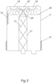
- Fig. 3 shows another embodiment of the dispenser.
- This embodiment differs from the dispenser in Fig. 1 in that, like the dispenser in Fig. 2 , it contains a vertical pipe 27 in which the inner surface 31 is highly reflective in the UV range.
- the UV radiation source contains three separate sources: the central source 32 located above the open end of the pipe 27 and two additional sources of lower power 33, 34 located on the sides of the central source 32.
- Each of the sources uses semiconductor UV LEDs (UV-C LED). Use of multiple UV sources allows to optimize the performance of UV sources.
- the central source 32 can be narrowly directed, so that most of its radiation falls into the inner space of the pipe 27, while the central source can switch on at full power when water enters the tank 11 through the pipe 27 and switch off or operate at a reduced power for the rest of the time.
- the side or additional sources 33 and 34 also switch on when water enters the tank 11, and after dispensing continue operating at reduced power or can switch on periodically to maintain the microbiological purity of water in the tank 11 when water is not dispensed to consumers, since the maintenance of microbiological purity of water in the tank requires much lower UV radiation intensity
Landscapes
- Engineering & Computer Science (AREA)
- Mechanical Engineering (AREA)
- Health & Medical Sciences (AREA)
- Toxicology (AREA)
- Life Sciences & Earth Sciences (AREA)
- Hydrology & Water Resources (AREA)
- Environmental & Geological Engineering (AREA)
- Water Supply & Treatment (AREA)
- Chemical & Material Sciences (AREA)
- Organic Chemistry (AREA)
- Physical Water Treatments (AREA)
- Devices For Dispensing Beverages (AREA)
- Devices That Are Associated With Refrigeration Equipment (AREA)
Claims (8)
- Ein Trinkwasserspender mit einer UV-Desinfektionsvorrichtung hat folgende Teile:
einen Körper (10) und folgende im Körper (10) installierte Teile:ein Einlassrohr (18) zum Anschluss an eine externe Wasserversorgung;einen Kaltwasserbehälter (11), der mit einer Kühleinrichtung (12) ausgestattet ist sowie einen mit Wasser gefüllten Unterteil (25) und einen Oberteil (26) hat, in dem sich ein Lufthohlraum bildet wird, wenn der Kaltwasserbehälter (11) mit Wasser gefüllt ist;einen Wassereinlass (13), der mit dem Einlassrohr (18) verbunden ist, und einen Wasserauslass (14), der mit dem Auslassrohr (20) verbunden ist, ein Auslassventil (21) zur Wasserabgabe an Verbraucher, das mit dem Auslassrohr (20) verbunden ist, undeine im Kaltwasserbehälter (11) installierte UV-Strahlungsquelle (17), mit folgender Charakteristik:der Wassereinlass (13) ist in Form eines vertikalen Rohrs (27) ausgeführt, das in dem Kaltwasserbehälter (11) platziert ist und dessen oberes Ende (29) offen ist und unteres Ende (28) mit dem Einlassrohr (18) verbunden ist; und wobeidie UV-Strahlungsquelle (17) im Oberteil (26) des Kaltwasserbehälters (11) über dem offenen oberen Ende (29) des vertikalen Rohrs (27) des Wassereinlasses (13) installiert ist. - Der Wasserspender gemäß den unter Nr. 1 beschriebenen Forderungen, bei dem das vertikale Rohr (27) zylindrisch ist.
- Der Wasserspender gemäß den unter Nr. 2 beschriebenen Forderungen, bei dem der Durchmesser des vertikalen Rohrs (27) im Bereich zwischen 10 mm und 50 mm liegt.
- Der Wasserspender gemäß den unter Nr. 1 beschriebenen Forderungen, bei dem bei dem als die UV-Strahlungsquelle (17) eine LED verwendet wird.
- Der Wasserspender gemäß den unter Nr. 4 beschriebenen Forderungen, bei dem als die UV-Strahlungsquelle (17) mehrere LEDs verwendet werden.
- Der Wasserspender gemäß den unter Nr. 4 oder 5 beschriebenen Forderungen, bei dem die innere Oberfläche des vertikalen Rohrs (27) die UV-Strahlung reflektiert.
- Der Wasserspender gemäß den unter Nr. 1 beschriebenen Forderungen, zusätzlich ausgestattet mit einer Steuervorrichtung (22) und einem mit der Steuervorrichtung verbundenem Einlassventil (19) zur Regelung der Wasserzufuhr zum Kaltwasserbehälter (11) sowie einen im Kaltwasserbehälter (11) platzierten Wasserstandssensor (15), wobei die Steuervorrichtung (22) so konfiguriert ist, dass der Wasserstand (30) im Kaltwasserbehälter zwischen den festgelegten oberen und unteren Grenzwerten gehalten wird.
- Der Wasserspender gemäß den unter Nr. 7 beschriebenen Forderungen, bei dem der festgelegte obere Grenzwert des Wasserstandes über dem offenen oberen Ende (29) des vertikalen Rohrs (27) des Wassereinlasses (13) liegt und der untere festgelegte Grenzwert des Wasserstandes nicht tiefer als das offene obere Ende (29) des vertikalen Rohrs (27) des Wassereinlasses (13) ist.
Applications Claiming Priority (1)
| Application Number | Priority Date | Filing Date | Title |
|---|---|---|---|
| PCT/IB2021/054526 WO2022248909A1 (en) | 2021-05-25 | 2021-05-25 | Drinking water dispenser with ultraviolet disinfection device |
Publications (3)
| Publication Number | Publication Date |
|---|---|
| EP4347477A1 EP4347477A1 (de) | 2024-04-10 |
| EP4347477B1 true EP4347477B1 (de) | 2025-03-26 |
| EP4347477C0 EP4347477C0 (de) | 2025-03-26 |
Family
ID=76502757
Family Applications (1)
| Application Number | Title | Priority Date | Filing Date |
|---|---|---|---|
| EP21733189.1A Active EP4347477B1 (de) | 2021-05-25 | 2021-05-25 | Trinkwasserspender mit ultraviolett-desinfektionsvorrichtung |
Country Status (4)
| Country | Link |
|---|---|
| US (1) | US12577130B2 (de) |
| EP (1) | EP4347477B1 (de) |
| JP (1) | JP2024521154A (de) |
| WO (1) | WO2022248909A1 (de) |
Family Cites Families (8)
| Publication number | Priority date | Publication date | Assignee | Title |
|---|---|---|---|---|
| US6139726A (en) | 1998-12-29 | 2000-10-31 | Uv Cooling Technologies | Treated water dispensing system |
| US6483119B1 (en) | 1999-09-23 | 2002-11-19 | Wayne A. Baus | Ultraviolet treatment for liquid dispensing unit |
| JP2006062720A (ja) | 2004-08-27 | 2006-03-09 | Sanden Corp | 飲料供給装置 |
| JP5304107B2 (ja) * | 2008-08-28 | 2013-10-02 | 株式会社寺岡精工 | 給水装置 |
| KR20100111537A (ko) * | 2009-04-07 | 2010-10-15 | 성선옥 | 근접살균방식의 자외선살균기 및 이를 이용한 정수기 |
| US20160278424A1 (en) | 2015-03-27 | 2016-09-29 | Rayvio Corporation | System and method for dispensing uv treated materials |
| JP7205128B2 (ja) * | 2018-09-20 | 2023-01-17 | 東芝ライテック株式会社 | 流体殺菌装置 |
| CN110272088A (zh) * | 2019-07-10 | 2019-09-24 | 深圳市深紫源光学有限公司 | 一种深紫外杀菌装置 |
-
2021
- 2021-05-25 EP EP21733189.1A patent/EP4347477B1/de active Active
- 2021-05-25 WO PCT/IB2021/054526 patent/WO2022248909A1/en not_active Ceased
- 2021-05-25 US US18/564,014 patent/US12577130B2/en active Active
- 2021-05-25 JP JP2023572642A patent/JP2024521154A/ja active Pending
Also Published As
| Publication number | Publication date |
|---|---|
| JP2024521154A (ja) | 2024-05-28 |
| US12577130B2 (en) | 2026-03-17 |
| WO2022248909A1 (en) | 2022-12-01 |
| EP4347477C0 (de) | 2025-03-26 |
| EP4347477A1 (de) | 2024-04-10 |
| US20240239691A1 (en) | 2024-07-18 |
Similar Documents
| Publication | Publication Date | Title |
|---|---|---|
| US6648174B2 (en) | Treated water dispensing system | |
| US6139726A (en) | Treated water dispensing system | |
| US8421032B2 (en) | Disinfecting device having a power supply and a fluid outlet | |
| KR100900300B1 (ko) | 물분배기 | |
| EP3495325B1 (de) | Uv-wasserbehandlung in trinkwassertank | |
| EP2730535B1 (de) | Wasserspender mit ozon-luftsterilisationskammer | |
| JP2016507367A (ja) | 液体浄化装置及び方法 | |
| US20160002021A1 (en) | Water dispenser | |
| CN111013308A (zh) | Uv光氧催化废气净化器 | |
| CN209536957U (zh) | 饮用水设备 | |
| EP4347477B1 (de) | Trinkwasserspender mit ultraviolett-desinfektionsvorrichtung | |
| RU2831793C2 (ru) | Диспенсер питьевой воды с устройством ультрафиолетовой дезинфекции | |
| KR100923644B1 (ko) | 정수기의 살균장치 | |
| EP1489048A1 (de) | Vorrichtung zur Trinkwasserversorgung | |
| KR101046185B1 (ko) | 냉장고용 살균 정수장치 | |
| RU207845U1 (ru) | Диспенсер питьевой воды с устройством ультрафиолетовой дезинфекции | |
| KR101397385B1 (ko) | 음료 공급장치 | |
| KR101732822B1 (ko) | 이중 살균기능을 가진 냉온수기 | |
| JP2005137495A (ja) | 飲料供給装置 | |
| JP2014169805A (ja) | 冷温水供給装置 | |
| US20260070816A1 (en) | Bottled water dispenser with a system for treating water in a bottle with UV radiation | |
| RU214753U1 (ru) | Диспенсер питьевой воды со встроенной системой уф-стерилизации | |
| US20250340461A1 (en) | Drinking Water Dispenser with Built-in UV Sterilization System | |
| KR200275515Y1 (ko) | 냉온 정수기 구조 | |
| KR20120045950A (ko) | 살균 정수기 |
Legal Events
| Date | Code | Title | Description |
|---|---|---|---|
| STAA | Information on the status of an ep patent application or granted ep patent |
Free format text: STATUS: UNKNOWN |
|
| STAA | Information on the status of an ep patent application or granted ep patent |
Free format text: STATUS: THE INTERNATIONAL PUBLICATION HAS BEEN MADE |
|
| PUAI | Public reference made under article 153(3) epc to a published international application that has entered the european phase |
Free format text: ORIGINAL CODE: 0009012 |
|
| STAA | Information on the status of an ep patent application or granted ep patent |
Free format text: STATUS: REQUEST FOR EXAMINATION WAS MADE |
|
| 17P | Request for examination filed |
Effective date: 20231220 |
|
| AK | Designated contracting states |
Kind code of ref document: A1 Designated state(s): AL AT BE BG CH CY CZ DE DK EE ES FI FR GB GR HR HU IE IS IT LI LT LU LV MC MK MT NL NO PL PT RO RS SE SI SK SM TR |
|
| DAV | Request for validation of the european patent (deleted) | ||
| DAX | Request for extension of the european patent (deleted) | ||
| GRAP | Despatch of communication of intention to grant a patent |
Free format text: ORIGINAL CODE: EPIDOSNIGR1 |
|
| STAA | Information on the status of an ep patent application or granted ep patent |
Free format text: STATUS: GRANT OF PATENT IS INTENDED |
|
| INTG | Intention to grant announced |
Effective date: 20241022 |
|
| RIC1 | Information provided on ipc code assigned before grant |
Ipc: C02F 1/32 20230101ALI20241015BHEP Ipc: C02F 9/00 20230101ALI20241015BHEP Ipc: B67D 3/00 20060101AFI20241015BHEP |
|
| GRAS | Grant fee paid |
Free format text: ORIGINAL CODE: EPIDOSNIGR3 |
|
| GRAA | (expected) grant |
Free format text: ORIGINAL CODE: 0009210 |
|
| STAA | Information on the status of an ep patent application or granted ep patent |
Free format text: STATUS: THE PATENT HAS BEEN GRANTED |
|
| AK | Designated contracting states |
Kind code of ref document: B1 Designated state(s): AL AT BE BG CH CY CZ DE DK EE ES FI FR GB GR HR HU IE IS IT LI LT LU LV MC MK MT NL NO PL PT RO RS SE SI SK SM TR |
|
| REG | Reference to a national code |
Ref country code: GB Ref legal event code: FG4D |
|
| REG | Reference to a national code |
Ref country code: CH Ref legal event code: EP |
|
| REG | Reference to a national code |
Ref country code: DE Ref legal event code: R096 Ref document number: 602021028149 Country of ref document: DE |
|
| REG | Reference to a national code |
Ref country code: IE Ref legal event code: FG4D |
|
| U01 | Request for unitary effect filed |
Effective date: 20250425 |
|
| U07 | Unitary effect registered |
Designated state(s): AT BE BG DE DK EE FI FR IT LT LU LV MT NL PT RO SE SI Effective date: 20250502 |
|
| U20 | Renewal fee for the european patent with unitary effect paid |
Year of fee payment: 5 Effective date: 20250513 |
|
| PG25 | Lapsed in a contracting state [announced via postgrant information from national office to epo] |
Ref country code: RS Free format text: LAPSE BECAUSE OF FAILURE TO SUBMIT A TRANSLATION OF THE DESCRIPTION OR TO PAY THE FEE WITHIN THE PRESCRIBED TIME-LIMIT Effective date: 20250626 |
|
| PGFP | Annual fee paid to national office [announced via postgrant information from national office to epo] |
Ref country code: GB Payment date: 20250530 Year of fee payment: 5 |
|
| PG25 | Lapsed in a contracting state [announced via postgrant information from national office to epo] |
Ref country code: NO Free format text: LAPSE BECAUSE OF FAILURE TO SUBMIT A TRANSLATION OF THE DESCRIPTION OR TO PAY THE FEE WITHIN THE PRESCRIBED TIME-LIMIT Effective date: 20250626 |
|
| PG25 | Lapsed in a contracting state [announced via postgrant information from national office to epo] |
Ref country code: HR Free format text: LAPSE BECAUSE OF FAILURE TO SUBMIT A TRANSLATION OF THE DESCRIPTION OR TO PAY THE FEE WITHIN THE PRESCRIBED TIME-LIMIT Effective date: 20250326 |
|
| PG25 | Lapsed in a contracting state [announced via postgrant information from national office to epo] |
Ref country code: GR Free format text: LAPSE BECAUSE OF FAILURE TO SUBMIT A TRANSLATION OF THE DESCRIPTION OR TO PAY THE FEE WITHIN THE PRESCRIBED TIME-LIMIT Effective date: 20250627 |
|
| PG25 | Lapsed in a contracting state [announced via postgrant information from national office to epo] |
Ref country code: SM Free format text: LAPSE BECAUSE OF FAILURE TO SUBMIT A TRANSLATION OF THE DESCRIPTION OR TO PAY THE FEE WITHIN THE PRESCRIBED TIME-LIMIT Effective date: 20250326 |
|
| PG25 | Lapsed in a contracting state [announced via postgrant information from national office to epo] |
Ref country code: ES Free format text: LAPSE BECAUSE OF FAILURE TO SUBMIT A TRANSLATION OF THE DESCRIPTION OR TO PAY THE FEE WITHIN THE PRESCRIBED TIME-LIMIT Effective date: 20250326 |
|
| PG25 | Lapsed in a contracting state [announced via postgrant information from national office to epo] |
Ref country code: PL Free format text: LAPSE BECAUSE OF FAILURE TO SUBMIT A TRANSLATION OF THE DESCRIPTION OR TO PAY THE FEE WITHIN THE PRESCRIBED TIME-LIMIT Effective date: 20250326 |
|
| PG25 | Lapsed in a contracting state [announced via postgrant information from national office to epo] |
Ref country code: SK Free format text: LAPSE BECAUSE OF FAILURE TO SUBMIT A TRANSLATION OF THE DESCRIPTION OR TO PAY THE FEE WITHIN THE PRESCRIBED TIME-LIMIT Effective date: 20250326 |
|
| PG25 | Lapsed in a contracting state [announced via postgrant information from national office to epo] |
Ref country code: IS Free format text: LAPSE BECAUSE OF FAILURE TO SUBMIT A TRANSLATION OF THE DESCRIPTION OR TO PAY THE FEE WITHIN THE PRESCRIBED TIME-LIMIT Effective date: 20250726 |
|
| REG | Reference to a national code |
Ref country code: CH Ref legal event code: H13 Free format text: ST27 STATUS EVENT CODE: U-0-0-H10-H13 (AS PROVIDED BY THE NATIONAL OFFICE) Effective date: 20251223 |
|
| PG25 | Lapsed in a contracting state [announced via postgrant information from national office to epo] |
Ref country code: CH Free format text: LAPSE BECAUSE OF NON-PAYMENT OF DUE FEES Effective date: 20250531 |
|
| PG25 | Lapsed in a contracting state [announced via postgrant information from national office to epo] |
Ref country code: CZ Free format text: LAPSE BECAUSE OF FAILURE TO SUBMIT A TRANSLATION OF THE DESCRIPTION OR TO PAY THE FEE WITHIN THE PRESCRIBED TIME-LIMIT Effective date: 20250326 |
|
| PG25 | Lapsed in a contracting state [announced via postgrant information from national office to epo] |
Ref country code: MC Free format text: LAPSE BECAUSE OF FAILURE TO SUBMIT A TRANSLATION OF THE DESCRIPTION OR TO PAY THE FEE WITHIN THE PRESCRIBED TIME-LIMIT Effective date: 20250326 |
|
| PLBE | No opposition filed within time limit |
Free format text: ORIGINAL CODE: 0009261 |
|
| STAA | Information on the status of an ep patent application or granted ep patent |
Free format text: STATUS: NO OPPOSITION FILED WITHIN TIME LIMIT |
|
| REG | Reference to a national code |
Ref country code: CH Ref legal event code: L10 Free format text: ST27 STATUS EVENT CODE: U-0-0-L10-L00 (AS PROVIDED BY THE NATIONAL OFFICE) Effective date: 20260211 |
|
| 26N | No opposition filed |
Effective date: 20260105 |
|
| PG25 | Lapsed in a contracting state [announced via postgrant information from national office to epo] |
Ref country code: IE Free format text: LAPSE BECAUSE OF NON-PAYMENT OF DUE FEES Effective date: 20250525 |