EP4347397B1 - Fernbedienungssystem für ein magnuseffektflugzeug - Google Patents
Fernbedienungssystem für ein magnuseffektflugzeug Download PDFInfo
- Publication number
- EP4347397B1 EP4347397B1 EP22730518.2A EP22730518A EP4347397B1 EP 4347397 B1 EP4347397 B1 EP 4347397B1 EP 22730518 A EP22730518 A EP 22730518A EP 4347397 B1 EP4347397 B1 EP 4347397B1
- Authority
- EP
- European Patent Office
- Prior art keywords
- cylinder
- aircraft
- pair
- rotatable elements
- longitudinal axis
- Prior art date
- Legal status (The legal status is an assumption and is not a legal conclusion. Google has not performed a legal analysis and makes no representation as to the accuracy of the status listed.)
- Active
Links
Images


Classifications
-
- B—PERFORMING OPERATIONS; TRANSPORTING
- B64—AIRCRAFT; AVIATION; COSMONAUTICS
- B64C—AEROPLANES; HELICOPTERS
- B64C23/00—Influencing air flow over aircraft surfaces, not otherwise provided for
- B64C23/08—Influencing air flow over aircraft surfaces, not otherwise provided for using Magnus effect
-
- B—PERFORMING OPERATIONS; TRANSPORTING
- B64—AIRCRAFT; AVIATION; COSMONAUTICS
- B64B—LIGHTER-THAN AIR AIRCRAFT
- B64B1/00—Lighter-than-air aircraft
- B64B1/40—Balloons
- B64B1/50—Captive balloons
- B64B1/52—Captive balloons attaching trailing entanglements
-
- B—PERFORMING OPERATIONS; TRANSPORTING
- B64—AIRCRAFT; AVIATION; COSMONAUTICS
- B64C—AEROPLANES; HELICOPTERS
- B64C13/00—Control systems or transmitting systems for actuating flying-control surfaces, lift-increasing flaps, air brakes, or spoilers
- B64C13/02—Initiating means
- B64C13/16—Initiating means actuated automatically, e.g. responsive to gust detectors
- B64C13/18—Initiating means actuated automatically, e.g. responsive to gust detectors using automatic pilot
-
- B—PERFORMING OPERATIONS; TRANSPORTING
- B64—AIRCRAFT; AVIATION; COSMONAUTICS
- B64C—AEROPLANES; HELICOPTERS
- B64C39/00—Aircraft not otherwise provided for
- B64C39/02—Aircraft not otherwise provided for characterised by special use
- B64C39/022—Tethered aircraft
-
- B—PERFORMING OPERATIONS; TRANSPORTING
- B64—AIRCRAFT; AVIATION; COSMONAUTICS
- B64F—GROUND OR AIRCRAFT-CARRIER-DECK INSTALLATIONS SPECIALLY ADAPTED FOR USE IN CONNECTION WITH AIRCRAFT; DESIGNING, MANUFACTURING, ASSEMBLING, CLEANING, MAINTAINING OR REPAIRING AIRCRAFT, NOT OTHERWISE PROVIDED FOR; HANDLING, TRANSPORTING, TESTING OR INSPECTING AIRCRAFT COMPONENTS, NOT OTHERWISE PROVIDED FOR
- B64F3/00—Ground installations specially adapted for captive aircraft
-
- B—PERFORMING OPERATIONS; TRANSPORTING
- B64—AIRCRAFT; AVIATION; COSMONAUTICS
- B64U—UNMANNED AERIAL VEHICLES [UAV]; EQUIPMENT THEREFOR
- B64U10/00—Type of UAV
- B64U10/60—Tethered aircraft
-
- F—MECHANICAL ENGINEERING; LIGHTING; HEATING; WEAPONS; BLASTING
- F03—MACHINES OR ENGINES FOR LIQUIDS; WIND, SPRING, OR WEIGHT MOTORS; PRODUCING MECHANICAL POWER OR A REACTIVE PROPULSIVE THRUST, NOT OTHERWISE PROVIDED FOR
- F03D—WIND MOTORS
- F03D5/00—Other wind motors
- F03D5/06—Other wind motors the wind-engaging parts swinging to-and-fro and not rotating
-
- F—MECHANICAL ENGINEERING; LIGHTING; HEATING; WEAPONS; BLASTING
- F05—INDEXING SCHEMES RELATING TO ENGINES OR PUMPS IN VARIOUS SUBCLASSES OF CLASSES F01-F04
- F05B—INDEXING SCHEME RELATING TO WIND, SPRING, WEIGHT, INERTIA OR LIKE MOTORS, TO MACHINES OR ENGINES FOR LIQUIDS COVERED BY SUBCLASSES F03B, F03D AND F03G
- F05B2240/00—Components
- F05B2240/20—Rotors
- F05B2240/201—Rotors using the Magnus-effect
-
- F—MECHANICAL ENGINEERING; LIGHTING; HEATING; WEAPONS; BLASTING
- F05—INDEXING SCHEMES RELATING TO ENGINES OR PUMPS IN VARIOUS SUBCLASSES OF CLASSES F01-F04
- F05B—INDEXING SCHEME RELATING TO WIND, SPRING, WEIGHT, INERTIA OR LIKE MOTORS, TO MACHINES OR ENGINES FOR LIQUIDS COVERED BY SUBCLASSES F03B, F03D AND F03G
- F05B2240/00—Components
- F05B2240/90—Mounting on supporting structures or systems
- F05B2240/92—Mounting on supporting structures or systems on an airbourne structure
- F05B2240/921—Mounting on supporting structures or systems on an airbourne structure kept aloft due to aerodynamic effects
-
- F—MECHANICAL ENGINEERING; LIGHTING; HEATING; WEAPONS; BLASTING
- F05—INDEXING SCHEMES RELATING TO ENGINES OR PUMPS IN VARIOUS SUBCLASSES OF CLASSES F01-F04
- F05B—INDEXING SCHEME RELATING TO WIND, SPRING, WEIGHT, INERTIA OR LIKE MOTORS, TO MACHINES OR ENGINES FOR LIQUIDS COVERED BY SUBCLASSES F03B, F03D AND F03G
- F05B2260/00—Function
- F05B2260/50—Kinematic linkage, i.e. transmission of position
- F05B2260/504—Kinematic linkage, i.e. transmission of position using flat or V-belts and pulleys
Definitions
- the invention relates to the technical field of piloting systems for an aircraft of the Magnus effect type.
- such a system makes it possible to dispense with an electric motor on board the aircraft to rotate the cylinder around the longitudinal axis (i.e. the pitch axis of the aircraft).
- the cylinder is rotated around the longitudinal axis by a mechanical transfer with the rotating element via the connecting cable, which makes it possible to reduce energy conversion losses compared to the state of the art.
- the choice of the connecting cable is not constrained, the connecting cable does not have to be electrically conductive, unlike the state of the art, which makes it possible to overcome the problem of potential degradation of the hoops.
- the rotational drive of the cylinder around the longitudinal axis is thus offset, for example within a land or sea station where the rotating element and the means for driving the rotating element can be arranged, which makes it possible to lighten the aircraft.
- an advantage provided by the pair of rotating elements is to control the two directions of rotation of the aircraft cylinder around the longitudinal axis (the pitch axis), which makes it possible to avoid crossing portions of the connecting cable. Controlling the length of the connecting cable between the aircraft and the rotating elements makes it possible to create a back-and-forth movement of the aircraft in lift.
- the pair of rotating elements comprises first and second rotating elements.
- the first and second rotating elements can be independent in the sense that the first and second rotating elements can have a different rotation speed (winding, unwinding, stopping).
- the system according to the invention may comprise one or more of the following characteristics.
- the connecting cable is wound around the cylinder of the aircraft so that the rotational movement of the rotating elements, driven by the drive means, is mechanically transmitted to the cylinder of the aircraft by friction of the connecting cable so as to rotate the cylinder around the longitudinal axis.
- an advantage provided is to allow a direct mechanical transfer between the connecting cable and the aircraft cylinder to control the aircraft along the pitch axis by controlling the rotational speed of the cylinder around the longitudinal axis.
- the system comprises a transmission device arranged to cooperate mechanically with the connecting cable and the cylinder of the aircraft so that the rotational movement of the rotating elements, driven by the drive means, is mechanically transmitted to the cylinder of the aircraft by the transmission device so as to rotate the cylinder around the longitudinal axis.
- an advantage provided is to allow an indirect mechanical transfer between the connecting cable and the aircraft cylinder (via the transmission device) to control the aircraft along the pitch axis by controlling the rotational speed of the cylinder around the longitudinal axis.
- the transmission device comprises a configuration in which a mechanical transmission to the cylinder of the rotational movement of the rotating element is interrupted, so that the cylinder is free to rotate around the longitudinal axis; the transmission device preferably comprising a freewheel or a clutch.
- an advantage provided by this configuration is to be able to rewind the connecting cable without transmitting power to the aircraft cylinder, when the mechanical transmission is interrupted.
- the aircraft in lift, is intended to be subjected to a wind; the system comprising control means, configured to control the drive means as a function of the wind.
- an advantage provided is to be able to control the torque and rotational speed of the rotating element.
- the aircraft comprises guidance means, arranged to guide the connecting cable between two positions relative to the cylinder defining a maximum roll angle.
- an advantage provided is to facilitate the piloting of the aircraft by controlling the roll angle of the aircraft.
- the guidance means are arranged relative to the cylinder to maintain a movement of the connecting cable along an axis parallel to the longitudinal axis of the cylinder between the two positions defining the maximum roll angle.
- the cylinder has first and second longitudinal ends; the system comprising first and/or second attachment cables, fixed respectively to the first and/or second longitudinal ends of the cylinder, and connected respectively to first and/or second winches.
- an advantage provided is to be able to control the aircraft along the roll axis by controlling the length of the first and/or second tether cables between the aircraft and respectively the first and/or second winches.
- the system comprises an anchoring zone, arranged at a distance from the aircraft, and the connecting cable is fixed to the anchoring zone.
- an advantage provided by the anchoring zone is to allow the control of the torque on the cylinder independently of the balance between the aerodynamic forces and the sum of the tensions in the parts of the connecting cable.
- an advantage provided is to be able to transmit the desired power to the cylinder at any time, including when rewinding the connecting cable or the additional connecting cable.
- one advantage provided is to be able to control the aircraft along the yaw axis by introducing a differential in rotational speeds between the pair of rotating elements and the additional pair of rotating elements. This results in a differential drag that generates a torque around the yaw axis of the aircraft. It is then possible to do without a tail unit to stabilize the aircraft along the yaw axis. It is also possible to envisage dynamic flights with the possibility of maneuvering the aircraft around the yaw axis by making “8” shaped trajectories at a given altitude to make round trips. "Dynamic flight” means a flight in which the aircraft is in constant motion and continuously adapts to the characteristics of the wind.
- an advantage provided is to be able to transmit the desired power to the corresponding cylinder at any time, including when rewinding one of the two connecting cables of the corresponding assembly.
- the rotating element is a drum of a winch.
- the connecting cable is arranged to connect the aircraft to the rotating element so that a movement of the aircraft in lift can be mechanically transmitted to the rotating element.
- one advantage provided is to be able to recover the mechanical energy from the movement of the aircraft in lift.
- the aircraft in lift, has a yaw axis, and is intended to be subjected to a wind; the system comprising a tail device, arranged to stabilize the aircraft along the yaw axis as a function of the wind.
- Cylinder 1 forms a wing of the aircraft. Rotating cylinder 1 about the longitudinal axis Y makes it possible to exploit the Magnus effect to increase the lift of the aircraft.
- Cylinder 1 has first and second longitudinal ends 10, 11 (illustrated in figure 8 ).
- the aircraft advantageously comprises first and second discs 100, 110, mounted respectively at the first and second longitudinal ends 10, 11 of the cylinder 1 so as to improve the aerodynamic performance of the aircraft.
- the first and second discs 100, 110 are advantageously removably mounted at the first and second longitudinal ends 10, 11 of the cylinder 1 in order to disengage from the cylinder 1 to provide a landing gear function.
- the first and second discs 100, 110 are advantageously free to rotate relative to the cylinder 1 when the aircraft is on the ground. In flight, the first and second discs 100, 110 are integral in rotation with the cylinder 1.
- the cylinder 1 advantageously has a circular cross-section, having a diameter denoted D.
- the cylinder 1 advantageously has a length, denoted L, along the longitudinal axis Y verifying an L/D ratio of between 6 and 12.
- the cylinder 1 is advantageously filled with a gas having a density lower than the density of air, so as to create Archimedean lift.
- the aircraft then has a mass lower than the mass of air so that the aircraft is an aerostat.
- the gas may be hydrogen or helium.
- the gas may be under pressure, for example between 20 mbar and 50 mbar depending on the dimensions of the cylinder 1, so that the pressure of the gas inside the cylinder 1 is higher than atmospheric pressure.
- the cylinder 1 may be in the form of a balloon.
- the cylinder 1 may have an envelope made of a gas-tight textile material. The pressurized gas makes it possible to stiffen the cylinder 1.
- the cylinder 1 is advantageously provided with reinforcing members 12, which can be produced in the form of longitudinal rods extending along an axis parallel to the longitudinal axis Y of the cylinder 1, in order to improve the mechanical resistance of the cylinder 1.
- the cylinder 1 may comprise internal elements 13, for example made in the form of discs, arranged to reinforce the mechanical strength of the cylinder 1.
- the internal elements 13 may also be arranged to form compartments inside the cylinder 1, for example for a pressurizing gas.
- the aircraft advantageously comprises a dynamoelectric machine, arranged to convert mechanical energy (rotation of the cylinder 1 around the longitudinal axis Y) into electrical energy.
- the electrical energy generated by the dynamoelectric machine can electrically power components of the aircraft, such as sensors, on-board computers, de-icing devices, devices for maintaining the pressure of the gas inside the cylinder 1, etc. It is also possible to use other types of machines for converting the mechanical energy of the rotation of the cylinder 1 around the longitudinal axis Y (e.g. conversion into heat for de-icing).
- the aircraft is advantageously equipped with means for acquiring the characteristics of the wind blowing on the cylinder 1, such as an anemometer, configured to send data representative of the characteristics of the wind V to processing/control means such as a microcontroller.
- the processing/control means may be on board the aircraft.
- the aircraft is advantageously equipped with means for acquiring parameters specific to the cylinder 1, such as an inertial unit configured to transmit to the means processing/controlling data representing the orientation of cylinder 1 relative to the wind V, the speed of cylinder 1, the acceleration of cylinder 1, etc.
- the aircraft may comprise first and second cylinders 1, 1' extending respectively along first and second longitudinal axes Y, Y', the first and second cylinders 1, 1' being movable in rotation respectively around the first and second longitudinal axes Y, Y'.
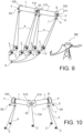
- the aircraft comprises a support structure 5, arranged to support the cylinder 1.
- the cylinder 1 is mounted so as to be able to rotate on the support structure 5 about the longitudinal axis Y.
- the support structure 5 may comprise a set of branches forming a frame for the cylinder.
- the support structure may comprise two longitudinal branches 50, each extending along a first axis parallel to the longitudinal axis Y of the cylinder 1.
- the support structure 5 may comprise two lateral branches 51, each extending along a second axis perpendicular to the first axis, and connected to the longitudinal branches 50.
- the cylinder 1 may be mounted so as to be able to rotate about the longitudinal axis Y on the lateral branches 51 of the support structure 5, for example by means of mechanical axes 510 and mechanical bearings 511 (notably illustrated in Figure 7 ).
- the aircraft in lift, has a yaw axis Z and is intended to be subjected to a wind V.
- the longitudinal axis Y along which the cylinder 1 extends is the pitch axis.
- the yaw axis Z and the roll axis X are perpendicular to each other, and extend in a plane perpendicular to the longitudinal axis Y (i.e. the pitch axis).
- the pitch axis Y is horizontal
- the yaw axis Z is vertical
- the roll axis X is horizontal.
- the pitch axis Y, the yaw axis Z and the roll axis X are perpendicular to each other, as illustrated in Figure 7 .
- the system comprises a connecting element 53 (illustrated in figures 9 And 15 ), rectilinear, arranged to connect the first and second cylinders 1, 1'.
- the aircraft may include propellers (not shown), arranged on the support structure 5 to facilitate takeoff and landing of the aircraft.
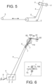
- the rotating element 2 is advantageously a drum of a winch, which makes it possible to transform a rotational movement of the drum into a linear movement of the connecting cable 4 and vice versa.
- the linear speed of the connecting cable 4 can be between 0 ms -1 and 40 ms -1 .
- the connecting cable 4 is advantageously wound around the drum of the winch.
- the system may comprise two pairs of rotating elements 2, each rotating element 2 being produced in the form of a return pulley. Each pair of rotating elements 2 is arranged to pinch the connecting cable 4.
- the cylinder 1 may be provided with a transmission shaft 30 driving the cylinder 1 in rotation by pulsations, the transmission shaft 30 being mounted on the aircraft against the action of elastic return means 31, for example a spring.
- the connecting cable 4 connects the transmission shaft 30 to the rotating element 2.
- the rotating element 2 gives pulsations to the connecting cable 4 which pulls on the transmission shaft 30 and sets the cylinder 1 in rotation around the longitudinal axis Y.
- the aircraft is advantageously provided with a horizontal stabilizer 82 (see paragraph “Empennage device”), arranged to compensate for the torque created by the elastic return means 31.
- the drive means 3 may comprise a motor, preferably electric, arranged to drive a rotational movement of the rotating element 2.
- the drive means 3 may drive the rotating element 2 directly or indirectly.
- An example of indirect drive is illustrated in Figure 3 where linear motors 3 pull the connecting cable 4 and thereby drive the rotating elements 2 in rotation.
- the drive means are arranged to drive a rotational movement of the pair of rotating elements 2.
- the drive means are arranged to drive the first and/or the second rotating element 2 of the pair.
- the first and second rotating elements may be independent in the sense that the first and second rotating elements may have a different rotational speed (winding, unwinding, stopping). In other words, it is possible to introduce a differential in rotational speeds between the first and second rotating elements 2 of the pair.
- the aircraft in lift, is intended to be subjected to a wind V.
- the system advantageously comprises control means, configured to control the drive means as a function of the wind V.
- control means configured to control the drive means as a function of the wind V.
- the connecting cable 4 may be made of a dielectric material.
- the connecting cable 4 advantageously has a high voltage resistance.
- the connecting cable 4 may be made of a polymer material, for example high-density polyethylene.
- the connecting cable 4 may comprise a gas conduit, arranged to supply the cylinder 1 with pressurized gas.
- the system may comprise an anchoring zone ZA, arranged at a distance from the aircraft, and the connecting cable 4 is fixed to the anchoring zone ZA.
- the connecting cable 4 can be connected to a pulley 40 so as to form a continuous loop.
- the drive means 3 can thus be offset relative to the rotating elements 2.
- the connecting cable 4 can be connected to a set of rotating elements 2 so as to form a continuous loop and the drive means 3 are offset relative to the rotating elements 2.
- One of the two rotating elements 2 illustrated in the Figure 5 can be locked in rotation so as to allow a translation of the connecting cable 4 in order to rotate the cylinder 1 around the longitudinal axis Y.
- the connecting cable 4 is wound around the cylinder 1 of the aircraft so that the rotational movement of the rotating element 2, driven by the drive means 3, is mechanically transmitted to the cylinder 1 of the aircraft by friction of the connecting cable 4 so as to rotate the cylinder 1 around the longitudinal axis Y.
- the system comprises a transmission device 6 arranged to cooperate mechanically with the connecting cable 4 and the cylinder 1 of the aircraft so that the rotational movement of the rotary element 2, driven by the drive means 3, is mechanically transmitted to the cylinder 1 of the aircraft by the transmission device 6 so as to rotate the cylinder 1 about the longitudinal axis Y.
- the transmission device 6 advantageously comprises a configuration in which a mechanical transmission to the cylinder 1 of the rotational movement of the rotary element 2 is interrupted, so that the cylinder 1 is free to rotate about the longitudinal axis Y.
- the transmission device 6 preferably comprises a freewheel or a clutch.
- the transmission device 6 is advantageously mounted at the first and second longitudinal ends 10, 11 of the cylinder 1, as illustrated in FIG. Figure 9 .
- the transmission device 6 is arranged to cooperate mechanically with the connecting cable 4 and the cylinder 1 of the aircraft so that the rotational movement of the pair of rotating elements 2, driven by the drive means 3, is mechanically transmitted to the cylinder 1 of the aircraft by the transmission device 6 so as to rotate the cylinder 1 about the longitudinal axis Y.
- the transmission device 6 advantageously comprises a configuration in which a mechanical transmission to the cylinder 1 of the rotational movement of the pair of rotating elements 2 is interrupted, so that the cylinder 1 is free to rotate about the longitudinal axis Y.
- the aircraft advantageously comprises guidance means, arranged to guide the connecting cable 4 between two positions relative to the cylinder 1 defining a roll angle. maximum.
- the guide means advantageously comprise rings 7, mounted on the support structure 5 of the aircraft, and adapted to receive the connecting cable 4.
- the guide means advantageously comprise a tube 70, arranged on the support structure 5 of the aircraft. Two rings 7, each adapted to receive the connecting cable 4, are advantageously slidably mounted on the tube 70, for example using a slider 700, so as to define the maximum roll angle.
- the guide means may be rolling elements (eg pulleys, rollers) to minimize friction with the connecting cable 4.
- the guide means are advantageously arranged to guide the connecting cable 4 to the surface S of the cylinder 1.
- the system is advantageously configured to control the winding angle of the connecting cable 4 to the surface S of the cylinder 1 (and therefore the transmitted power) as a function of the tensions of the connecting cable 4 on either side of the cylinder 1, for example using the capstan formula (also called the Eytelwein formula) known to those skilled in the art.
- the system may comprise first and/or second attachment cables CA, fixed respectively to the first and/or second longitudinal ends 10, 11 of the cylinder 1, and connected respectively to first and/or second winches 2'.
- the system comprises a tether cable CA fixed to a longitudinal end 10, 11 of the cylinder 1.
- the system comprises two CA attachment cables each fixed to a separate longitudinal end 10, 11 of the cylinder 1.
- the system may include a tether cable CA attached to the elbow member 52 and connected to a winch 2' to control the pitch angle of the aircraft.
- the drive means 3 are arranged to drive a rotational movement of the pair of rotating elements 2 and the additional pair of rotating elements 2.
- the connecting cable 4 is arranged to connect the pair of rotating elements 2 to the first cylinder 1 of the aircraft so that the rotational movement of the pair of rotating elements 2, driven by the drive means 3, is mechanically transmitted to the first cylinder 1 of the aircraft so as to rotate the first cylinder 1 around the first longitudinal axis Y.
- the additional connecting cable 4 is arranged to connect the additional pair of rotating elements 2 to the second cylinder 1' of the aircraft so that the rotational movement of the additional pair of rotating elements 2, driven by the drive means 3, is mechanically transmitted to the second cylinder 1' of the aircraft so as to rotate the second cylinder 1' around the second longitudinal axis Y'.
- each cylinder 1, 1' being connected to at least one pair of rotating elements 2.
- the aircraft in lift, has a yaw axis Z, and is intended to be subjected to a wind V.
- the system advantageously comprises a tail device 8, arranged to stabilize the aircraft along the yaw axis Z as a function of the wind V.
- the tail device 8 is mounted on the support structure 5 of the aircraft. More precisely, the tail device 8 can be mounted mobile in rotation on a longitudinal branch 50 of the support structure 5, around the first axis of the longitudinal branch 50.
- the empennage device 8 advantageously comprises an arm 80 extending along a longitudinal axis.
- the arm 80 has first and second opposite ends.
- the arm 80 is pivotally mounted on said longitudinal branch 50 of the support structure 5, around the first axis of the longitudinal branch 50, for example using an articulation mechanism. 800.
- the empennage device 8 advantageously comprises a first stabilizer 81, called vertical, extending in a first direction perpendicular to the longitudinal axis of the arm 80. When the longitudinal axis of the arm 80 is horizontal, the first direction is vertical.
- the first stabilizer 81 is fixed on the first end of the arm 80.
- the empennage device 8 advantageously comprises a second stabilizer 82, called horizontal, extending in a second direction, perpendicular to the first direction and to the longitudinal axis of the arm 80.
- a second stabilizer 82 extending in a second direction, perpendicular to the first direction and to the longitudinal axis of the arm 80.
- the second direction is horizontal.
- the second stabilizer 82 is fixed on the first end of the arm 80. The second stabilizer 82 allows passive alignment of the empennage device 8 with the apparent wind V to maximize the stability effect of the first stabilizer 81.
- the first stabilizer 81 advantageously comprises two independent control surfaces 810, mounted to pivot around the first direction in which the first stabilizer 81 extends. As illustrated in Figures 17a and 17b , the pivot angle of the two control surfaces 810 relative to the first direction of the first stabilizer 81 is adapted to the wind direction V so as to generate a kinetic moment around the yaw axis Z. The position of the longitudinal axis of the arm 80 is parallel to the wind direction V.
- the empennage device 8 advantageously comprises a sensor module 83, mounted at the second end of the arm 80.
- the sensor module 83 can be adapted to measure the direction and speed of the wind V, the position, altitude, speed and acceleration of the aircraft.
- the sensor module 83 can be mounted on the support structure 5 of the aircraft.
- the connecting cable 4 is advantageously arranged to connect the aircraft to the rotating element 2 so that a movement of the aircraft in lift can be mechanically transmitted to the rotating element 2.
- the system advantageously comprises a converter, arranged to convert a rotation of the rotating element 2, obtained by a mechanical transmission of the movement of the aircraft in lift, into energy.
- the converter may comprise an electrical generator, arranged to convert a rotation of the rotating element into electrical energy.
- the drive means 3 consume energy to wind the connecting cable 4 while the movements of the aircraft in lift make it possible to unwind the connecting cable 4 and to recover energy.
- the electrical generator for example located in the station, can be electrically connected to an RE electrical network (illustrated in figure 9 ) or an energy storage system via electrical interconnection means 9.
- the electrical network RE can supply the station, in particular the drive means 3, via the electrical interconnection means 9.
- the hydraulic/pneumatic G generators belong to a hydraulic/pneumatic circuit 90 comprising a low-pressure reservoir 900 and a high-pressure reservoir 901.
- the hydraulic/pneumatic G generators pump the fluid (e.g. oil or compressed air) of the hydraulic/pneumatic circuit 90 from the low-pressure reservoir 900 (e.g. atmosphere for a pneumatic circuit 90) to the high-pressure reservoir 901.
- the energy is therefore stored by the pressure of the fluid in the high-pressure reservoir 901.
- the mechanical transmission TM switches from the first position to the second position. Energy is consumed by the flow of fluid from the high-pressure reservoir 901 to the low-pressure reservoir 900.
- the hydraulic/pneumatic circuit 90 is connected to an additional hydraulic/pneumatic motor M' which turns an electric generator G'. Electricity production can therefore be smoothed via this temporary storage system (of the order of a few hours), or electricity production can be adapted according to the needs of electricity consumption demand.
Landscapes
- Engineering & Computer Science (AREA)
- Aviation & Aerospace Engineering (AREA)
- Mechanical Engineering (AREA)
- Remote Sensing (AREA)
- Automation & Control Theory (AREA)
- Sustainable Development (AREA)
- Life Sciences & Earth Sciences (AREA)
- Sustainable Energy (AREA)
- Chemical & Material Sciences (AREA)
- Combustion & Propulsion (AREA)
- General Engineering & Computer Science (AREA)
- Transmission Devices (AREA)
- Toys (AREA)
Claims (15)
- Fernbedienungssystem für ein Flugzeug, umfassend:- ein Flugzeug vom Typ Magnus-Effekt, umfassend einen Zylinder (1), der sich entlang einer Längsachse (Y) erstreckt, wobei der Zylinder (1) um die Längsachse (Y) drehbeweglich ist;- ein Paar drehbarer Elemente (2), das von dem Flugzeug entfernt angeordnet ist;- Antriebsmittel (3), die dazu angeordnet sind, eine Drehbewegung des Paares drehbarer Elemente (2) zu bewirken;- ein Verbindungskabel (4), das dazu angeordnet ist, das Paar drehbarer Elemente (2) mit dem Zylinder (1) des Flugzeugs zu verbinden, sodass die Drehbewegung des Paares drehbarer Elemente (2), die durch die Antriebsmittel (3) bewirkt wird, mechanisch auf den Zylinder (1) des Flugzeugs übertragen wird, um den Zylinder (1) um die Längsachse (Y) in Drehung zu versetzen.
- System nach Anspruch 1, wobei das Verbindungskabel (4) um den Zylinder (1) des Flugzeugs gewickelt ist, sodass die Drehbewegung des Paares drehbarer Elemente (2), die durch die Antriebsmittel (3) bewirkt wird, durch Reibung des Verbindungskabels (4) mechanisch auf den Zylinder (1) des Flugzeugs übertragen wird, um den Zylinder (1) um die Längsachse (Y) in Drehung zu versetzen.
- System nach Anspruch 1, umfassend eine Übertragungsvorrichtung (6), die dazu angeordnet ist, mit dem Verbindungskabel (4) und dem Zylinder (1) des Flugzeugs mechanisch zusammenzuwirken, sodass die Drehbewegung des Paares drehbarer Elemente (2), die durch die Antriebsmittel (3) bewirkt wird, durch die Übertragungsvorrichtung (6) mechanisch auf den Zylinder (1) des Flugzeugs übertragen wird, um den Zylinder (1) um die Längsachse (Y) in Drehung zu versetzen.
- System nach Anspruch 3, wobei die Übertragungsvorrichtung (6) eine Konfiguration umfasst, in der eine mechanische Übertragung der Drehbewegung des Paares drehbarer Elemente (2) auf den Zylinder (1) unterbrochen ist, sodass der Zylinder (1) um die Längsachse (Y) frei drehen kann; wobei die Übertragungsvorrichtung (6) vorzugsweise einen Freilauf oder eine Kupplung umfasst.
- System nach einem der Ansprüche 1 bis 4, wobei das Flugzeug im Schwebezustand dazu bestimmt ist, einem Wind (V) ausgesetzt zu sein; wobei das System Steuermittel umfasst, die dazu konfiguriert sind, die Antriebsmittel (3) in Abhängigkeit des Windes (V) zu steuern.
- System nach einem der Ansprüche 1 bis 5, wobei das Flugzeug Führungsmittel (7) umfasst, die dazu angeordnet sind, das Verbindungskabel (4) zwischen zwei Positionen in Bezug auf den Zylinder (1) zu führen, die einen maximalen Rollwinkel bilden.
- System nach einem der Ansprüche 1 bis 5, wobei der Zylinder (1) ein erstes und ein zweites Längsende (10, 11) aufweist; wobei das System ein erstes und/oder ein zweites Haltekabel (CA) umfasst, die jeweils an dem ersten und/oder dem zweiten Längsende (10, 11) des Zylinders (1) befestigt sind und jeweils mit einer ersten und/oder einer zweiten Winde (2') verbunden sind.
- System nach einem der Ansprüche 1 bis 7, umfassend:- ein zusätzliches Paar drehbarer Elemente (2), das von dem Flugzeug entfernt angeordnet ist;- ein zusätzliches Verbindungskabel (4);wobei bei dem System:- die Antriebsmittel (3) dazu angeordnet sind, eine Drehbewegung des zusätzlichen Paares drehbarer Elemente (2) zu bewirken;- das zusätzliche Verbindungskabel (4) dazu angeordnet ist, das zusätzliche Paar drehbarer Elemente (2) mit dem Zylinder (1) des Flugzeugs zu verbinden, sodass die Drehbewegung des zusätzlichen Paares drehbarer Elemente (2), die durch die Antriebsmittel (3) bewirkt wird, mechanisch auf den Zylinder (1) des Flugzeugs übertragen wird, um den Zylinder (1) um die Längsachse (Y) in Drehung zu versetzen.
- System nach Anspruch 8, wobei:- das Flugzeug einen ersten und einen zweiten Zylinder (1, 1') umfasst, die sich jeweils entlang einer ersten bzw. einer zweiten Längsachse (Y, Y') erstrecken, wobei der erste und der zweite Zylinder (1, 1') jeweils um die erste bzw. die zweite Längsachse (Y, Y') drehbeweglich sind;- das Verbindungskabel (4) dazu angeordnet ist, das Paar drehbarer Elemente (2) mit dem ersten Zylinder (1) des Flugzeugs zu verbinden, sodass die Drehbewegung des Paares drehbarer Elemente (2), die durch die Antriebsmittel (3) bewirkt wird, mechanisch auf den ersten Zylinder (1) des Flugzeugs übertragen wird, um den ersten Zylinder (1) um die erste Längsachse (Y) in Drehung zu versetzen;- das zusätzliche Verbindungskabel (4) dazu angeordnet ist, das zusätzliche Paar drehbarer Elemente (2) mit dem zweiten Zylinder (1') des Flugzeugs zu verbinden, sodass die Drehbewegung des zusätzlichen Paares drehbarer Elemente (2), die durch die Antriebsmittel (3) bewirkt wird, mechanisch auf den zweiten Zylinder (1') des Flugzeugs übertragen wird, um den zweiten Zylinder (1') um die zweite Längsachse (Y') in Drehung zu versetzen.
- System nach einem der Ansprüche 1 bis 7, umfassend eine erste und eine zweite Anordnung, die jeweils Folgendes beinhalten:- zwei Paare drehbarer Elemente (2), die von dem Flugzeug entfernt angeordnet sind, und- zwei Verbindungskabel (4);wobei bei dem System:- das Flugzeug einen ersten und einen zweiten Zylinder (1, 1') umfasst, die sich jeweils entlang einer ersten bzw. einer zweiten Längsachse (Y, Y') erstrecken, wobei der erste und der zweite Zylinder (1, 1') jeweils um die erste bzw. die zweite Längsachse (Y, Y') drehbeweglich sind;- die Antriebsmittel (3) dazu angeordnet sind, eine Drehbewegung der drehbaren Elemente (2) der ersten und der zweiten Anordnung zu bewirken;- jedes Verbindungskabel (4) der ersten Anordnung dazu angeordnet ist, ein Paar drehbarer Elemente (2) der ersten Anordnung mit dem ersten Zylinder (1) des Flugzeugs zu verbinden, sodass die Drehbewegung der drehbaren Elemente (2) der ersten Anordnung, die durch die Antriebsmittel (3) bewirkt wird, mechanisch auf den ersten Zylinder (1) des Flugzeugs übertragen wird, um den ersten Zylinder (1) um die erste Längsachse (Y) in Drehung zu versetzen;- jedes Verbindungskabel (4) der zweiten Anordnung dazu angeordnet ist, ein Paar drehbarer Elemente (2) der zweiten Anordnung mit dem zweiten Zylinder (1') des Flugzeugs zu verbinden, sodass die Drehbewegung der drehbaren Elemente (2) der zweiten Anordnung, die durch die Antriebsmittel (3) bewirkt wird, mechanisch auf den zweiten Zylinder (1') des Flugzeugs übertragen wird, um den zweiten Zylinder (1') um die zweite Längsachse (Y') in Drehung zu versetzen.
- System nach Anspruch 9 oder 10, wobei das Flugzeug im Schwebezustand eine Gierachse (Z) aufweist und dazu bestimmt ist, einem Wind (V) ausgesetzt zu sein; wobei das System ein gebogenes Element (52) umfasst, das Folgendes aufweist:- einen ersten Arm (520), der mit dem ersten Zylinder (1) verbunden ist;- einen zweiten Arm (521), der mit dem zweiten Zylinder (1') verbunden ist;wobei der erste und der zweite Arm (520, 521) einen Pfeilungswinkel bilden, der dazu angepasst ist, das Flugzeug in Abhängigkeit des Windes (V) entlang der Gierachse (Z) zu stabilisieren.
- System nach einem der Ansprüche 1 bis 11, wobei das drehbare Element (2) eine Trommel einer Winde ist.
- System nach einem der Ansprüche 1 bis 12, wobei das Verbindungskabel (4) dazu angeordnet ist, das Flugzeug mit dem Paar drehbarer Elemente (2) zu verbinden, sodass eine Bewegung des Flugzeugs im Schwebezustand mechanisch auf die drehbaren Elemente (2) übertragen werden kann.
- System nach Anspruch 13, umfassend einen Wandler, der dazu angeordnet ist, eine Drehung des Paares drehbarer Elemente (2), die durch eine mechanische Übertragung (TM) der Bewegung des Flugzeugs im Schwebezustand erhalten wird, in eine Energie umzuwandeln.
- System nach einem der Ansprüche 1 bis 14, wobei das Flugzeug im Schwebezustand eine Gierachse (Z) aufweist und dazu bestimmt ist, einem Wind (V) ausgesetzt zu sein; wobei das System eine Leitwerkvorrichtung (8) umfasst, die dazu angeordnet ist, das Flugzeug in Abhängigkeit des Windes (V) entlang der Gierachse (Z) zu stabilisieren.
Applications Claiming Priority (2)
| Application Number | Priority Date | Filing Date | Title |
|---|---|---|---|
| FR2105554A FR3123317B1 (fr) | 2021-05-27 | 2021-05-27 | Système de pilotage à distance d’un aéronef à effet Magnus |
| PCT/EP2022/064342 WO2022248631A1 (fr) | 2021-05-27 | 2022-05-25 | Systeme de pilotage a distance d'un aeronef a effet magnus |
Publications (3)
| Publication Number | Publication Date |
|---|---|
| EP4347397A1 EP4347397A1 (de) | 2024-04-10 |
| EP4347397B1 true EP4347397B1 (de) | 2025-05-07 |
| EP4347397C0 EP4347397C0 (de) | 2025-05-07 |
Family
ID=76601445
Family Applications (1)
| Application Number | Title | Priority Date | Filing Date |
|---|---|---|---|
| EP22730518.2A Active EP4347397B1 (de) | 2021-05-27 | 2022-05-25 | Fernbedienungssystem für ein magnuseffektflugzeug |
Country Status (6)
| Country | Link |
|---|---|
| US (1) | US12291324B2 (de) |
| EP (1) | EP4347397B1 (de) |
| JP (1) | JP2024519541A (de) |
| AU (1) | AU2022279576A1 (de) |
| FR (1) | FR3123317B1 (de) |
| WO (1) | WO2022248631A1 (de) |
Families Citing this family (1)
| Publication number | Priority date | Publication date | Assignee | Title |
|---|---|---|---|---|
| RU2762848C1 (ru) * | 2021-08-25 | 2021-12-23 | Владимир Александрович Вьюрков | Летательный аппарат на основе эффекта Магнуса и способ его работы |
Family Cites Families (10)
| Publication number | Priority date | Publication date | Assignee | Title |
|---|---|---|---|---|
| US4659940A (en) * | 1982-04-27 | 1987-04-21 | Cognitronics Corporation | Power generation from high altitude winds |
| NL1004508C2 (nl) * | 1996-11-12 | 1998-05-14 | Wubbo Johannes Ockels | Windgedreven aandrijfinrichting. |
| US6523781B2 (en) * | 2000-08-30 | 2003-02-25 | Gary Dean Ragner | Axial-mode linear wind-turbine |
| US7335000B2 (en) * | 2005-05-03 | 2008-02-26 | Magenn Power, Inc. | Systems and methods for tethered wind turbines |
| US7602077B2 (en) * | 2005-05-03 | 2009-10-13 | Magenn Power, Inc. | Systems and methods for tethered wind turbines |
| US7275719B2 (en) * | 2005-11-28 | 2007-10-02 | Olson Gaylord G | Wind drive apparatus for an aerial wind power generation system |
| PT103489B (pt) * | 2006-05-31 | 2008-11-28 | Omnidea Lda | Sistema modular de aproveitamento de recursos atmosféricos |
| PT105565A (pt) * | 2011-03-15 | 2012-09-17 | Omnidea Lda | Aeronave |
| DE102013205781B4 (de) * | 2013-04-02 | 2017-01-26 | Deutsches Zentrum für Luft- und Raumfahrt e.V. | Windkraftanlage |
| FR3043386B1 (fr) * | 2015-11-09 | 2018-10-19 | Garrett Smith | Aeronef mis en œuvre dans un systeme de production d’energie electrique |
-
2021
- 2021-05-27 FR FR2105554A patent/FR3123317B1/fr active Active
-
2022
- 2022-05-25 AU AU2022279576A patent/AU2022279576A1/en active Pending
- 2022-05-25 EP EP22730518.2A patent/EP4347397B1/de active Active
- 2022-05-25 JP JP2023573062A patent/JP2024519541A/ja active Pending
- 2022-05-25 US US18/564,210 patent/US12291324B2/en active Active
- 2022-05-25 WO PCT/EP2022/064342 patent/WO2022248631A1/fr not_active Ceased
Also Published As
| Publication number | Publication date |
|---|---|
| JP2024519541A (ja) | 2024-05-15 |
| FR3123317A1 (fr) | 2022-12-02 |
| AU2022279576A1 (en) | 2024-01-18 |
| EP4347397A1 (de) | 2024-04-10 |
| EP4347397C0 (de) | 2025-05-07 |
| FR3123317B1 (fr) | 2023-08-25 |
| US12291324B2 (en) | 2025-05-06 |
| WO2022248631A1 (fr) | 2022-12-01 |
| US20240262494A1 (en) | 2024-08-08 |
Similar Documents
| Publication | Publication Date | Title |
|---|---|---|
| CN102159458B (zh) | 用于空中发电机的系链操纵 | |
| CN102439298B (zh) | 转子飞机发电、控制装置及方法 | |
| US20100032948A1 (en) | Method and apparatus for operating and controlling airborne wind energy generation craft and the generation of electrical energy using such craft | |
| JP5908989B2 (ja) | 凧地上ステーション及びそれを使用するシステム | |
| US9650157B2 (en) | Drive mechanisms for use in controlling rotation and twist of a tether | |
| US10301143B2 (en) | Sensor equipped tether guide with open tether channel | |
| FR3050385A1 (fr) | Drone comportant au moins trois rotors de sustentation et de propulsion | |
| US10280034B2 (en) | Floating counter-balanced levelwind carrier system | |
| EP2977323A1 (de) | Entfaltbare struktur mit federband | |
| US7641151B2 (en) | Electric sail for producing spacecraft propulsion | |
| EP4347397B1 (de) | Fernbedienungssystem für ein magnuseffektflugzeug | |
| US20170121036A1 (en) | Ground station for airborne wind turbine | |
| FR3023876A1 (fr) | Dispositif aeroporte | |
| WO2022008437A1 (fr) | Dispositif volant a decollage vertical | |
| US20190031340A1 (en) | Tether Guide with Two-Sided Open Tether Channel | |
| WO2017081406A1 (fr) | Aéronef mis en œuvre dans un système de production d'énergie électrique | |
| WO2015189684A1 (fr) | Aéronef convertible à aile basculante | |
| FR3020096A1 (fr) | Eolienne adaptative | |
| FR3051440A1 (fr) | Drone endurant a decollage et atterrissage verticaux optimise pour des missions en environnement complexe | |
| EP4158183B1 (de) | Vorrichtung zur energieerzeugung mit einem mindestens eine wasserstromturbine schleppenden luftschiff | |
| FR3058188A1 (fr) | Dispositif aeroporte | |
| FR3079208A1 (fr) | Dispositif aeroporte | |
| IT202000009280A1 (it) | Cavo di ritenuta per un velivolo senza pilota, base e sistema associato |
Legal Events
| Date | Code | Title | Description |
|---|---|---|---|
| STAA | Information on the status of an ep patent application or granted ep patent |
Free format text: STATUS: UNKNOWN |
|
| STAA | Information on the status of an ep patent application or granted ep patent |
Free format text: STATUS: THE INTERNATIONAL PUBLICATION HAS BEEN MADE |
|
| PUAI | Public reference made under article 153(3) epc to a published international application that has entered the european phase |
Free format text: ORIGINAL CODE: 0009012 |
|
| STAA | Information on the status of an ep patent application or granted ep patent |
Free format text: STATUS: REQUEST FOR EXAMINATION WAS MADE |
|
| 17P | Request for examination filed |
Effective date: 20231115 |
|
| AK | Designated contracting states |
Kind code of ref document: A1 Designated state(s): AL AT BE BG CH CY CZ DE DK EE ES FI FR GB GR HR HU IE IS IT LI LT LU LV MC MK MT NL NO PL PT RO RS SE SI SK SM TR |
|
| DAV | Request for validation of the european patent (deleted) | ||
| DAX | Request for extension of the european patent (deleted) | ||
| REG | Reference to a national code |
Ref country code: DE Ref legal event code: R079 Ipc: B64U0010600000 Ref country code: DE Ref legal event code: R079 Ref document number: 602022014357 Country of ref document: DE Free format text: PREVIOUS MAIN CLASS: B64C0039020000 Ipc: B64U0010600000 |
|
| GRAP | Despatch of communication of intention to grant a patent |
Free format text: ORIGINAL CODE: EPIDOSNIGR1 |
|
| STAA | Information on the status of an ep patent application or granted ep patent |
Free format text: STATUS: GRANT OF PATENT IS INTENDED |
|
| INTG | Intention to grant announced |
Effective date: 20241203 |
|
| RIC1 | Information provided on ipc code assigned before grant |
Ipc: F03D 5/06 20060101ALI20241125BHEP Ipc: F03D 3/00 20060101ALI20241125BHEP Ipc: B64F 3/00 20060101ALI20241125BHEP Ipc: B64B 1/56 20060101ALI20241125BHEP Ipc: B64B 1/52 20060101ALI20241125BHEP Ipc: B64C 23/08 20060101ALI20241125BHEP Ipc: B64C 39/02 20230101ALI20241125BHEP Ipc: B64U 10/60 20230101AFI20241125BHEP |
|
| GRAS | Grant fee paid |
Free format text: ORIGINAL CODE: EPIDOSNIGR3 |
|
| GRAA | (expected) grant |
Free format text: ORIGINAL CODE: 0009210 |
|
| STAA | Information on the status of an ep patent application or granted ep patent |
Free format text: STATUS: THE PATENT HAS BEEN GRANTED |
|
| AK | Designated contracting states |
Kind code of ref document: B1 Designated state(s): AL AT BE BG CH CY CZ DE DK EE ES FI FR GB GR HR HU IE IS IT LI LT LU LV MC MK MT NL NO PL PT RO RS SE SI SK SM TR |
|
| REG | Reference to a national code |
Ref country code: GB Ref legal event code: FG4D Free format text: NOT ENGLISH |
|
| REG | Reference to a national code |
Ref country code: CH Ref legal event code: EP |
|
| REG | Reference to a national code |
Ref country code: DE Ref legal event code: R096 Ref document number: 602022014357 Country of ref document: DE |
|
| REG | Reference to a national code |
Ref country code: IE Ref legal event code: FG4D Free format text: LANGUAGE OF EP DOCUMENT: FRENCH |
|
| U01 | Request for unitary effect filed |
Effective date: 20250527 |
|
| U07 | Unitary effect registered |
Designated state(s): AT BE BG DE DK EE FI FR IT LT LU LV MT NL PT RO SE SI Effective date: 20250605 |
|
| U20 | Renewal fee for the european patent with unitary effect paid |
Year of fee payment: 4 Effective date: 20250617 |
|
| PG25 | Lapsed in a contracting state [announced via postgrant information from national office to epo] |
Ref country code: ES Free format text: LAPSE BECAUSE OF FAILURE TO SUBMIT A TRANSLATION OF THE DESCRIPTION OR TO PAY THE FEE WITHIN THE PRESCRIBED TIME-LIMIT Effective date: 20250507 |
|
| PG25 | Lapsed in a contracting state [announced via postgrant information from national office to epo] |
Ref country code: NO Free format text: LAPSE BECAUSE OF FAILURE TO SUBMIT A TRANSLATION OF THE DESCRIPTION OR TO PAY THE FEE WITHIN THE PRESCRIBED TIME-LIMIT Effective date: 20250807 Ref country code: GR Free format text: LAPSE BECAUSE OF FAILURE TO SUBMIT A TRANSLATION OF THE DESCRIPTION OR TO PAY THE FEE WITHIN THE PRESCRIBED TIME-LIMIT Effective date: 20250808 |
|
| PG25 | Lapsed in a contracting state [announced via postgrant information from national office to epo] |
Ref country code: PL Free format text: LAPSE BECAUSE OF FAILURE TO SUBMIT A TRANSLATION OF THE DESCRIPTION OR TO PAY THE FEE WITHIN THE PRESCRIBED TIME-LIMIT Effective date: 20250507 |
|
| PG25 | Lapsed in a contracting state [announced via postgrant information from national office to epo] |
Ref country code: HR Free format text: LAPSE BECAUSE OF FAILURE TO SUBMIT A TRANSLATION OF THE DESCRIPTION OR TO PAY THE FEE WITHIN THE PRESCRIBED TIME-LIMIT Effective date: 20250507 |
|
| PG25 | Lapsed in a contracting state [announced via postgrant information from national office to epo] |
Ref country code: RS Free format text: LAPSE BECAUSE OF FAILURE TO SUBMIT A TRANSLATION OF THE DESCRIPTION OR TO PAY THE FEE WITHIN THE PRESCRIBED TIME-LIMIT Effective date: 20250807 |
|
| PG25 | Lapsed in a contracting state [announced via postgrant information from national office to epo] |
Ref country code: IS Free format text: LAPSE BECAUSE OF FAILURE TO SUBMIT A TRANSLATION OF THE DESCRIPTION OR TO PAY THE FEE WITHIN THE PRESCRIBED TIME-LIMIT Effective date: 20250907 |
|
| REG | Reference to a national code |
Ref country code: CH Ref legal event code: H13 Free format text: ST27 STATUS EVENT CODE: U-0-0-H10-H13 (AS PROVIDED BY THE NATIONAL OFFICE) Effective date: 20251223 |
|
| PG25 | Lapsed in a contracting state [announced via postgrant information from national office to epo] |
Ref country code: SM Free format text: LAPSE BECAUSE OF FAILURE TO SUBMIT A TRANSLATION OF THE DESCRIPTION OR TO PAY THE FEE WITHIN THE PRESCRIBED TIME-LIMIT Effective date: 20250507 |
|
| PG25 | Lapsed in a contracting state [announced via postgrant information from national office to epo] |
Ref country code: CH Free format text: LAPSE BECAUSE OF NON-PAYMENT OF DUE FEES Effective date: 20250531 |
|
| PG25 | Lapsed in a contracting state [announced via postgrant information from national office to epo] |
Ref country code: CZ Free format text: LAPSE BECAUSE OF FAILURE TO SUBMIT A TRANSLATION OF THE DESCRIPTION OR TO PAY THE FEE WITHIN THE PRESCRIBED TIME-LIMIT Effective date: 20250507 |
|
| PG25 | Lapsed in a contracting state [announced via postgrant information from national office to epo] |
Ref country code: SK Free format text: LAPSE BECAUSE OF FAILURE TO SUBMIT A TRANSLATION OF THE DESCRIPTION OR TO PAY THE FEE WITHIN THE PRESCRIBED TIME-LIMIT Effective date: 20250507 |
|
| PG25 | Lapsed in a contracting state [announced via postgrant information from national office to epo] |
Ref country code: MC Free format text: LAPSE BECAUSE OF FAILURE TO SUBMIT A TRANSLATION OF THE DESCRIPTION OR TO PAY THE FEE WITHIN THE PRESCRIBED TIME-LIMIT Effective date: 20250507 |
|
| PLBE | No opposition filed within time limit |
Free format text: ORIGINAL CODE: 0009261 |
|
| STAA | Information on the status of an ep patent application or granted ep patent |
Free format text: STATUS: NO OPPOSITION FILED WITHIN TIME LIMIT |
|
| REG | Reference to a national code |
Ref country code: CH Ref legal event code: L10 Free format text: ST27 STATUS EVENT CODE: U-0-0-L10-L00 (AS PROVIDED BY THE NATIONAL OFFICE) Effective date: 20260318 |
|
| PGFP | Annual fee paid to national office [announced via postgrant information from national office to epo] |
Ref country code: GB Payment date: 20260331 Year of fee payment: 5 |
|
| PG25 | Lapsed in a contracting state [announced via postgrant information from national office to epo] |
Ref country code: IE Free format text: LAPSE BECAUSE OF NON-PAYMENT OF DUE FEES Effective date: 20250525 |
|
| 26N | No opposition filed |
Effective date: 20260210 |