EP4347331B1 - Elektromechanisches bremssystem für ein kraftfahrzeug, verfahren zum betreiben des bremssystems - Google Patents
Elektromechanisches bremssystem für ein kraftfahrzeug, verfahren zum betreiben des bremssystems Download PDFInfo
- Publication number
- EP4347331B1 EP4347331B1 EP22730464.9A EP22730464A EP4347331B1 EP 4347331 B1 EP4347331 B1 EP 4347331B1 EP 22730464 A EP22730464 A EP 22730464A EP 4347331 B1 EP4347331 B1 EP 4347331B1
- Authority
- EP
- European Patent Office
- Prior art keywords
- electric motors
- control units
- assigned
- wheel
- braking system
- Prior art date
- Legal status (The legal status is an assumption and is not a legal conclusion. Google has not performed a legal analysis and makes no representation as to the accuracy of the status listed.)
- Active
Links
Images
Classifications
-
- B—PERFORMING OPERATIONS; TRANSPORTING
- B60—VEHICLES IN GENERAL
- B60T—VEHICLE BRAKE CONTROL SYSTEMS OR PARTS THEREOF; BRAKE CONTROL SYSTEMS OR PARTS THEREOF, IN GENERAL; ARRANGEMENT OF BRAKING ELEMENTS ON VEHICLES IN GENERAL; PORTABLE DEVICES FOR PREVENTING UNWANTED MOVEMENT OF VEHICLES; VEHICLE MODIFICATIONS TO FACILITATE COOLING OF BRAKES
- B60T13/00—Transmitting braking action from initiating means to ultimate brake actuator with power assistance or drive; Brake systems incorporating such transmitting means, e.g. air-pressure brake systems
- B60T13/74—Transmitting braking action from initiating means to ultimate brake actuator with power assistance or drive; Brake systems incorporating such transmitting means, e.g. air-pressure brake systems with electrical assistance or drive
- B60T13/741—Transmitting braking action from initiating means to ultimate brake actuator with power assistance or drive; Brake systems incorporating such transmitting means, e.g. air-pressure brake systems with electrical assistance or drive acting on an ultimate actuator
-
- B—PERFORMING OPERATIONS; TRANSPORTING
- B60—VEHICLES IN GENERAL
- B60T—VEHICLE BRAKE CONTROL SYSTEMS OR PARTS THEREOF; BRAKE CONTROL SYSTEMS OR PARTS THEREOF, IN GENERAL; ARRANGEMENT OF BRAKING ELEMENTS ON VEHICLES IN GENERAL; PORTABLE DEVICES FOR PREVENTING UNWANTED MOVEMENT OF VEHICLES; VEHICLE MODIFICATIONS TO FACILITATE COOLING OF BRAKES
- B60T17/00—Component parts, details, or accessories of power brake systems not covered by groups B60T8/00, B60T13/00 or B60T15/00, or presenting other characteristic features
- B60T17/18—Safety devices; Monitoring
- B60T17/22—Devices for monitoring or checking brake systems; Signal devices
- B60T17/221—Procedure or apparatus for checking or keeping in a correct functioning condition of brake systems
-
- B—PERFORMING OPERATIONS; TRANSPORTING
- B60—VEHICLES IN GENERAL
- B60T—VEHICLE BRAKE CONTROL SYSTEMS OR PARTS THEREOF; BRAKE CONTROL SYSTEMS OR PARTS THEREOF, IN GENERAL; ARRANGEMENT OF BRAKING ELEMENTS ON VEHICLES IN GENERAL; PORTABLE DEVICES FOR PREVENTING UNWANTED MOVEMENT OF VEHICLES; VEHICLE MODIFICATIONS TO FACILITATE COOLING OF BRAKES
- B60T7/00—Brake-action initiating means
- B60T7/12—Brake-action initiating means for automatic initiation; for initiation not subject to will of driver or passenger
-
- B—PERFORMING OPERATIONS; TRANSPORTING
- B60—VEHICLES IN GENERAL
- B60T—VEHICLE BRAKE CONTROL SYSTEMS OR PARTS THEREOF; BRAKE CONTROL SYSTEMS OR PARTS THEREOF, IN GENERAL; ARRANGEMENT OF BRAKING ELEMENTS ON VEHICLES IN GENERAL; PORTABLE DEVICES FOR PREVENTING UNWANTED MOVEMENT OF VEHICLES; VEHICLE MODIFICATIONS TO FACILITATE COOLING OF BRAKES
- B60T2270/00—Further aspects of brake control systems not otherwise provided for
- B60T2270/40—Failsafe aspects of brake control systems
- B60T2270/402—Back-up
-
- B—PERFORMING OPERATIONS; TRANSPORTING
- B60—VEHICLES IN GENERAL
- B60T—VEHICLE BRAKE CONTROL SYSTEMS OR PARTS THEREOF; BRAKE CONTROL SYSTEMS OR PARTS THEREOF, IN GENERAL; ARRANGEMENT OF BRAKING ELEMENTS ON VEHICLES IN GENERAL; PORTABLE DEVICES FOR PREVENTING UNWANTED MOVEMENT OF VEHICLES; VEHICLE MODIFICATIONS TO FACILITATE COOLING OF BRAKES
- B60T2270/00—Further aspects of brake control systems not otherwise provided for
- B60T2270/40—Failsafe aspects of brake control systems
- B60T2270/403—Brake circuit failure
-
- B—PERFORMING OPERATIONS; TRANSPORTING
- B60—VEHICLES IN GENERAL
- B60Y—INDEXING SCHEME RELATING TO ASPECTS CROSS-CUTTING VEHICLE TECHNOLOGY
- B60Y2306/00—Other features of vehicle sub-units
- B60Y2306/13—Failsafe arrangements
-
- B—PERFORMING OPERATIONS; TRANSPORTING
- B60—VEHICLES IN GENERAL
- B60Y—INDEXING SCHEME RELATING TO ASPECTS CROSS-CUTTING VEHICLE TECHNOLOGY
- B60Y2400/00—Special features of vehicle units
- B60Y2400/81—Braking systems
-
- B—PERFORMING OPERATIONS; TRANSPORTING
- B60—VEHICLES IN GENERAL
- B60Y—INDEXING SCHEME RELATING TO ASPECTS CROSS-CUTTING VEHICLE TECHNOLOGY
- B60Y2400/00—Special features of vehicle units
- B60Y2400/90—Driver alarms
Definitions
- the invention relates to an electromechanical braking system for a motor vehicle, with four wheel braking devices, with four primary electric motors, with four secondary electric motors, and with two control units.
- the invention relates to a method for operating such a braking system.
- braking systems must be designed in such a way that even in the event of a fault, i.e. if one of the components of the braking system fails, the vehicle can still be braked with a specified minimum deceleration.
- Braking systems usually provide a mechanical coupling of the brake pedal to the wheel brake devices for emergency actuation.
- the braking system is designed as a purely electromechanical, in particular as a so-called “brake-by-wire" braking system, in which no mechanical emergency actuation is possible, braking in the event of a fault is usually ensured by redundantly installing components of the braking system and/or by taking over redundancy functions for each other.
- the braking system according to the invention with the features of claim 1 is characterized in that the control units are designed to detect and/or evaluate sensor data from the wheel brake devices and/or sensors assigned to the motor vehicle, that each of the wheel brake devices is assigned one of the primary electric motors and one of the secondary electric motors for actuating the respective wheel brake devices, and that each of the control units controls two of the primary electric motors of two of the wheel brake devices and two of the secondary electric motors of two other of the Wheel brake devices are assigned to control the electric motors.
- the control units are designed to detect and/or evaluate sensor data from the wheel brake devices and/or sensors assigned to the motor vehicle, that each of the wheel brake devices is assigned one of the primary electric motors and one of the secondary electric motors for actuating the respective wheel brake devices, and that each of the control units controls two of the primary electric motors of two of the wheel brake devices and two of the secondary electric motors of two other of the Wheel brake devices are assigned to control the electric motors.
- Both control units, one of the primary electric motors and one of the secondary electric motors, are assigned to each of the wheel brake devices, so that the braking power of the braking system is still fully available even if one of the control units and/or one or more of the electric motors fails.
- the electric motors are not only functionally assigned to the respective wheel brake device, i.e. are operatively connected or mechanically coupled to the brake device, but are also spatially assigned, i.e. are arranged on the respective wheel brake device.
- Each of the secondary electric motors represents redundancy to one of the primary electric motors. The secondary electric motors are therefore only used if the respective primary electric motor fails.
- control units are in particular only functionally assigned to the wheel brake devices, i.e., they are electrically connected to the wheel brake devices via signaling, and are arranged anywhere in the vehicle, or are also spatially assigned to at least one of the wheel brake devices, i.e., in particular, they are arranged on the wheel brake device.
- control units By assigning control units to four wheel brake devices each, only two instead of eight control units are required to achieve the advantageous redundancy, thus reducing the complexity and cost of the braking system.
- additional, specially designed control units are advantageously dispensed with, or redundancy to such control units is created by installing at least one of the sensors redundantly and/or assigning it to both control units.
- the sensors are designed as rotor position sensors, speed sensors, airbag sensors, and/or distance sensors.
- Such a design of the sensors advantageously ensures that sensor data relevant for controlling the electric motors is directly recorded and/or evaluated by the control units. If the electric motors are designed, for example, as electrically annotated electric motors, the precise angular position of their rotors must be recorded for control. If the control unit records this directly via corresponding rotor position sensors, particularly advantageous, efficient control of the electric motors is guaranteed.
- speed sensors assigned to the wheels of the motor vehicle the wheel speed is determined and can be taken into account during braking, for example, to advantageously prevent one of the wheels from locking.
- At least one of the sensors is designed or arranged as a sensor close to the wheel, in particular as a microphone for noise monitoring. This also advantageously ensures direct recording and/or evaluation of relevant sensor data.
- the primary electric motors and/or the secondary electric motors are designed as electrically commutated or brushless electric motors.
- the electric motors are designed as electrically commutated electric motors, it is advantageously ensured that the actuation of the wheel brake devices is carried out efficiently.
- the primary electric motors are designed as electrically commutated electric motors, and the secondary electric motors as DC motors, which advantageously save space.
- the primary electric motors and/or the secondary electric motors are designed as three-phase asynchronous motors.
- the electric motors are advantageously designed to be cost-effective, in particular because such motors do not require rotor position sensors to detect the angular position of their rotors. It is also conceivable that one of the primary electric motors and one of the secondary electric motors can be used as a A common electric motor is designed with a primary motor winding and a secondary motor winding, in particular stator windings, wherein the primary motor winding and the secondary motor winding can be controlled independently of one another, and wherein when the primary motor winding is controlled, the electric motor is used as the primary electric motor and when the secondary motor winding is controlled, the electric motor is used as the secondary electric motor.
- the motor windings are assigned to the control units in a similar way to the assignment of the electric motors to the control units described above.
- the electric motors are also advantageously designed to be cost-effective, in particular because one of the primary electric motors and one of the secondary electric motors is arranged in a common housing with only one rotor.
- control units are each arranged closer to at least one of the two wheel brake devices, whose primary electric motor they are assigned to, than to one of the two wheel brake devices, whose secondary electric motor they are assigned to.
- Such an arrangement of the control units advantageously ensures that the length of the potentially error-prone electrical lines between at least one of the primary electric motors and the respective control unit is minimized, thus increasing the reliability of the control.
- the control units are arranged in a protected area of the motor vehicle, where they are exposed to lower temperature requirements and environmental influences than in the vicinity of the wheel brake devices, where they are less robust and thus advantageously more cost-effective.
- the two wheel brake devices whose primary electric motors are respectively assigned to the control units, are arranged on the same wheel axle of the motor vehicle.
- Such an arrangement advantageously ensures that the control units each assume a redundancy function for each other on the same wheel axle and thus, if one control unit fails, all wheel brake devices on both axles can still be actuated, namely by two of the primary electric motors on one axle and by two of the secondary Electric motors on the other axle.
- the braking system is designed with parallel redundancy on each axle.
- the two wheel brake devices whose primary electric motors the control units are respectively assigned to, are each assigned to different wheel axles of the motor vehicle and arranged at opposite ends of the wheel axles.
- Such an assignment advantageously ensures that each of the control units controls one of the primary and one of the secondary electric motors on each of the two axles, and thus, if one control unit fails, all wheel brake devices on both axles can still be actuated, namely on each axle by one of the primary and one of the secondary electric motors.
- the braking system is designed with diagonal axle redundancy.
- the method according to the invention with the features of claim 7 is characterized in that the electric motors and the control units of the braking system are monitored for functionality, and that a backup reaction is triggered in the event of a failure of one of the electric motors or one of the control units.
- Monitoring for functionality and triggering the backup reaction advantageously ensures that a failure of one of the electric motors and/or one of the control units is detected immediately and that the braking effect of the braking system is maintained.
- the secondary electric motor associated with the same wheel brake device is activated as a substitute reaction.
- the continued actuation of the wheel brake device is advantageously ensured.
- the other control unit is activated as a backup reaction.
- the actuation of all four wheel brake devices is advantageously ensured.
- a warning message is output as a substitute reaction, in particular on a display device assigned to a driver of the motor vehicle. Outputting the warning message advantageously ensures that the driver is immediately informed of the failure and can take appropriate measures, in particular aborting the journey and/or visiting a workshop.
- the warning message is preferably output simultaneously with one of the substitute reactions described above, in which a failure of another of the control units and/or another of the electric motors is compensated for by appropriately controlling one of the control units and/or one of the electric motors. If only the failure of one of the secondary electric motors is detected, no change in the control is necessary; outputting the warning message is sufficient.
- the warning message is preferably output depending on the relevance or severity of the failure, for example, using different color coding. For example, a failure of one of the secondary electric motors would be indicated only by a yellow warning light, while a failure of one of the primary electric motors and/or one of the control units would be indicated by a red warning light. Likewise, different instructions could advantageously be given to the driver, for example a request to immediately interrupt the journey in the event of the failure of one of the primary electric motors and/or one of the control units.
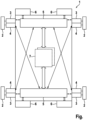
- the braking system 1 has exactly four wheel braking devices 2. Each of the wheel braking devices 2 is assigned to one of the wheels of the motor vehicle (also not shown).
- the braking system 1 is The embodiment is purely electromechanical and therefore has no hydraulic components or a hydraulic fluid circuit for actuating the wheel brake devices 2.
- the braking system 1 has exactly four primary electric motors 3 and exactly four secondary electric motors 4.
- the electric motors 3, 4 are designed as electrically commutated electric motors.
- Each of the wheel brake devices 2 is assigned one of the primary electric motors 3 and one of the secondary electric motors 4, each for actuating the respective wheel brake device 2.
- the braking system 1 has exactly two control units 5.
- Each of the control units 5 is assigned to two of the primary electric motors 3 of two of the wheel brake devices 2 and two of the secondary electric motors 4 of two other wheel brake devices 2 for controlling the electric motors 3, 4.
- the two wheel brake devices 2, whose primary electric motors 3 the control units 5 are each assigned to, are each assigned to the same wheel axle of the motor vehicle.
- the control units 5 are each arranged closer to the two wheel brake devices 2, whose primary electric motors 3 they are assigned to, than to the two wheel brake devices 2, whose secondary electric motors 4 they are assigned to.
- Each of the secondary electric motors 4 assumes a redundancy function for the primary electric motor 3 assigned to the same wheel brake device 2. If the corresponding primary electric motor 3 fails, the secondary electric motor 4 assigned to the same wheel brake device 2 is then activated.
- each of the control units 5 assumes a redundancy function for the other control unit 5. If one of the control units 5 fails, the other control unit 5 is then controlled.
- the control units 5 are further configured to acquire and/or evaluate sensor data from the wheel brake devices 2 and/or sensors 6 associated with the motor vehicle.
- the sensors are, in particular, rotor position sensors of one of the electric motors 3, 4, speed sensors of one of the wheels of the motor vehicle, airbag sensors of the motor vehicle, and/or distance sensors of the motor vehicle.
- control units 5 are connected to each other and to other control units 7 of the motor vehicle via a bus system, for example, Ethernet, Flexray, or CAN. At least one of the other control units 7 is configured, for example, to further process the sensor data acquired or evaluated by the control units 5.
- a bus system for example, Ethernet, Flexray, or CAN.
- At least one of the other control units 7 is configured, for example, to further process the sensor data acquired or evaluated by the control units 5.
- At least one of the further control units 7 is designed to monitor the electric motors 3, 4 and the control units 5 for functionality and, in the event of failure of one of the electric motors 3, 4 and/or one of the control units 5, to trigger suitable substitute reactions, in particular to change the control as described above and/or to output an error message.
Landscapes
- Engineering & Computer Science (AREA)
- Transportation (AREA)
- Mechanical Engineering (AREA)
- Regulating Braking Force (AREA)
- Valves And Accessory Devices For Braking Systems (AREA)
- Braking Systems And Boosters (AREA)
Description
- Die Erfindung betrifft ein elektromechanisches Bremssystem für ein Kraftfahrzeug, mit vier Radbremsvorrichtungen, mit vier primären Elektromotoren, mit vier sekundären Elektromotoren, und mit zwei Steuergeräten.
- Weiterhin betrifft die Erfindung ein Verfahren zum Betreiben eines derartigen Bremssystems.
- Zur Durchführung von automatisierten Bremsvorgängen, beispielsweise im Rahmen des autonomen Fahrens von Kraftfahrzeugen, muss ein Bremssystem eines Kraftfahrzeugs Aktuatoren aufweisen, die unabhängig von einer Bremspedalbetätigung durch einen Fahrer des Kraftfahrzeugs ansteuerbar sind. Ein derartiges Bremssystem ist beispielsweise als elektromechanisches Bremssystem ausgebildet und verfügt über je eine Radbremsvorrichtung für jedes Rad des Kraftfahrzeugs. Jede dieser Radbremsvorrichtungen wird von einem ihr zugeordneten Elektromotor betätigt, um das Kraftfahrzeug abzubremsen. Zur Ansteuerung der Elektromotoren weist das Bremssystem ein oder mehrere Steuergeräte auf.
- Es ist gesetzlich vorgeschrieben, dass Bremssysteme aus Sicherheitsgründen derart aufgebaut sein müssen, dass auch im Fehlerfall, also bei Ausfall einer der Komponenten des Bremssystems, das Kraftfahrzeug weiterhin mit einer vorgegebenen Mindestverzögerung gebremst werden kann. Bei hydraulischen Bremssystemen ist zur Notfallbetätigung üblicherweise eine mechanische Kopplung des Bremspedals mit den Radbremsvorrichtungen vorgesehen.
- Ist das Bremssystem jedoch als rein elektromechanisches, insbesondere als sogenanntes "Brake-by-Wire"-Bremssystem ausgebildet, bei dem keine mechanische Notfallbetätigung möglich ist, wird die Bremsung im Fehlerfall üblicherweise dadurch sichergestellt, dass Komponenten des Bremssystems redundant verbaut sind und/oder Redundanzfunktionen füreinander übernehmen.
- Derartige Bremssysteme mit redundanten Komponenten sind aus dem Stand der Technik bekannt. So offenbart beispielsweise die Offenlegungsschrift
EP 3 318 458 B1 eine elektrische Bremsvorrichtung für ein Kraftfahrzeug mit drei Steuereinheiten, wobei jede der Steuereinheiten jeweils zwei Bremsmechanismen zum Bremsen von zwei Rädern steuert, und wobei bei einem Ausfall einer oder zwei der Steuereinheiten zumindest eine der anderen Steuereinheiten die jeweiligen Bremsmechanismen der ausgefallenen Steuereinheit ansteuert, sodass das Kraftfahrzeug weiterhin gebremst werden kann. Insbesondere sind zwei der Steuereinheiten als Diagonalradsteuereinheiten, die dritte als Vorderradsteuereinheit ausgebildet. Alternativ ist es vorgesehen, die Steuereinheiten derart auszubilden, dass sie jeweils alle vier Bremsmechanismen ansteuern können. Eine Redundanz für die Bremsmechanismen selbst ist jedoch nicht vorgesehen, sodass bei Ausfall eines der Bremsmechanismen die Bremsleistung des Kraftfahrzeugs verringert ist. - Ein ähnliches Bremssystem ist auch aus der
US 2011/320099 A1 bekannt. - Das erfindungsgemäße Bremssystem mit den Merkmalen des Anspruchs 1 zeichnet sich dadurch aus, dass die Steuergeräte zur Erfassung und/oder Auswertung von Sensordaten von den Radbremsvorrichtungen und/oder dem Kraftfahrzeug zugeordneten Sensoren ausgebildet sind, dass jeder der Radbremsvorrichtungen jeweils einer der primären Elektromotoren und einer der sekundären Elektromotoren jeweils zur Betätigung der jeweiligen Radbremsvorrichtungen zugeordnet ist, und dass jedes der Steuergeräte jeweils zwei der primären Elektromotoren von zwei der Radbremsvorrichtungen und zwei der sekundären Elektromotoren von zwei anderen der Radbremsvorrichtungen zur Ansteuerung der Elektromotoren zugeordnet ist. Dadurch wird eine vorteilhafte Redundanz sowohl für die Betätigung der Bremsvorrichtungen als auch für die Ansteuerung der den Radbremsvorrichtung zugeordneten Elektromotoren erreicht. So sind jeder der Radbremsvorrichtungen beide Steuergeräte, einer der primären Elektromotoren und einer der sekundären Elektromotoren zugeordnet, sodass die Bremsleistung des Bremssystems auch bei einem Ausfall eines der Steuergeräte und/oder eines oder mehrerer der der Elektromotoren weiterhin vollständig vorhanden ist. Die Elektromotoren sind der jeweiligen Radbremsvorrichtung insbesondere nicht nur funktional zugeordnet, also mit der Bremsvorrichtung wirkverbunden beziehungsweise mechanisch gekoppelt, sondern auch räumlich zugeordnet, also an der jeweiligen Radbremsvorrichtung angeordnet. Jeder der sekundären Elektromotoren stellt eine Redundanz zu einem der primären Elektromotoren dar. Die sekundären Elektromotoren werden also nur verwendet, wenn der jeweilige primäre Elektromotor ausfällt. Es ist insbesondere denkbar, dass die sekundären Elektromotoren derart spezifiziert werden, dass mit ihnen lediglich eine gesetzlich geforderte Mindestverzögerung bei der Bremsung erreicht wird, und insoweit über eine geringere maximale elektrische Leistung und Größe als die primären Elektromotoren verfügen. So wird trotz vorhandener Redundanz vorteilhaft Bauraum gespart. Die Steuergeräte sind den Radbremsvorrichtungen insbesondere lediglich funktional zugeordnet, also mit den Radbremsvorrichtungen signaltechnisch elektrisch verbunden, und an einem beliebigen Ort im Fahrzeug angeordnet, oder jeweils zumindest einer der Radbremsvorrichtungen auch räumlich zugeordnet, also insbesondere an der Radbremsvorrichtung angeordnet. Durch die Zuordnung von Steuergeräten zu jeweils vier Radbremsvorrichtungen werden zum Erreichen der vorteilhaften Redundanz nur zwei anstatt acht Steuergeräte benötigt, sodass Komplexität und Kosten des Bremssystems gesenkt werden. Durch die Ausbildung der Steuergeräte zur Auswertung und/oder Erfassung von Sensordaten wird vorteilhaft auf weitere, speziell dazu ausgebildete Steuergeräte verzichtet oder eine Redundanz zu derartigen Steuergeräten geschaffen, in dem zumindest einer der Sensoren redundant verbaut und/oder beiden Steuergeräten zugeordnet ist.
- Gemäß einer bevorzugten Weiterbildung der Erfindung ist vorgesehen, dass die Sensoren als Rotorlagesensoren, Drehzahlsensoren, Airbagsensoren und/oder Abstandssensoren ausgebildet sind. Durch eine derartige Ausbildung der Sensoren ist vorteilhaft sichergestellt, dass für die Ansteuerung der Elektromotoren relevante Sensordaten von den Steuergeräten direkt erfasst und/oder ausgewertet werden. Sind die Elektromotoren beispielsweise als elektrisch kommentierte Elektromotoren ausgebildet, muss die genaue Winkellage ihrer Rotoren zur Ansteuerung erfasst werden. Erfasst das Steuergerät dies über entsprechende Rotorlagesensoren direkt, so ist eine besonders vorteilhafte, effiziente Ansteuerung der Elektromotoren gewährleistet. Mithilfe von den Rädern des Kraftfahrzeugs zugeordneten Drehzahlsensoren wird die Raddrehzahl ermittelt und kann bei der Bremsung berücksichtigt werden, beispielsweise um vorteilhaft ein Blockieren eines der Räder zu verhindern. Anhand der Sensordaten von Airbagsensoren und/oder Abstandssensoren sind Gefahrensituationen und/oder Unfallsituationen erkennbar, sodass die Steuergeräte bei Bedarf eine Bremsung, insbesondere eine Notfallbremsung, einleiten können. Vorzugsweise ist zumindest einer der Sensoren als radnaher Sensor ausgebildet oder angeordnet, insbesondere als Mikrofon zur Geräuschüberwachung. Dadurch ist ebenfalls eine direkte Erfassung und/oder Auswertung relevanter Sensordaten vorteilhaft sichergestellt.
- Gemäß einer bevorzugten Weiterbildung der Erfindung ist vorgesehen, dass die primären Elektromotoren und/oder die sekundären Elektromotoren als elektrisch kommutierte beziehungsweise bürstenlose Elektromotoren ausgebildet sind. Durch die Ausbildung der Elektromotoren als elektrisch kommutierte Elektromotoren ist vorteilhaft sichergestellt, dass die Betätigung der Radbremsvorrichtungen effizient durchgeführt wird. Vorzugsweise sind nur die primären Elektromotoren als elektrisch kommutierte Elektromotoren ausgebildet, und die sekundären Elektromotoren als Gleichstrommotoren, die vorteilhaft bauraumsparend sind. Alternativ sind die primären Elektromotoren und/oder die sekundären Elektromotoren als Drehstrom-Asynchronmotoren ausgebildet. Dadurch sind die Elektromotoren vorteilhaft kostengünstig ausgebildet, insbesondere, weil derartige Motoren keine Rotorlagesensoren zur Erfassung der Winkellage ihrer Rotoren benötigen. Ebenso ist es denkbar, dass jeweils einer der primären Elektromotoren und einer der sekundären Elektromotoren als ein gemeinsamer Elektromotor mit einer primären Motorwicklung und mit einer sekundären Motorwicklung, insbesondere Statorwicklungen, ausgebildet sind, wobei die primäre Motorwicklung und die sekundäre Motorwicklung unabhängig voneinander ansteuerbar sind, und wobei bei Ansteuerung der primären Motorwicklung der Elektromotor als primärer Elektromotor und bei Ansteuerung der sekundären Motorwicklung der Elektromotor als sekundärer Elektromotor verwendet wird. Die Zuordnung der Motorwicklungen zu den Steuergeräten erfolgt analog zu der vorstehend beschriebenen Zuordnung der Elektromotoren zu den Steuergeräten. Dadurch sind die Elektromotoren ebenfalls vorteilhaft kostengünstig ausgebildet, insbesondere, weil so jeweils einer der primären Elektromotoren und einer der sekundären Elektromotoren in einem gemeinsamen Gehäuse mit nur einem Rotor angeordnet sind.
- Gemäß einer bevorzugten Weiterbildung der Erfindung ist vorgesehen, dass die Steuergeräte jeweils näher zumindest zu einer der beiden Radbremsvorrichtungen angeordnet sind, deren primärem Elektromotor sie zugeordnet sind, als zu einer der beiden Radbremsvorrichtungen, deren sekundärem Elektromotor sie zugeordnet sind. Durch eine derartige Anordnung der Steuergeräte ist vorteilhaft sichergestellt, dass die Länge der potentiell fehleranfälligen, elektrischen Leitungen zwischen zumindest einem der primären Elektromotoren und dem jeweiligen Steuergerät minimiert wird, sodass die Zuverlässigkeit der Ansteuerung erhöht ist. Alternativ sind die Steuergeräte in einem geschützten Bereich des Kraftfahrzeugs angeordnet, in dem sie geringeren Temperaturanforderungen und Umwelteinflüssen als in der Nähe der Radbremsvorrichtungen ausgesetzt sind, wo sie weniger robust und damit vorteilhaft kostengünstiger ausgeführt sind.
- Gemäß einer bevorzugten Weiterbildung der Erfindung ist vorgesehen, dass die beiden Radbremsvorrichtungen, deren primären Elektromotoren die Steuergeräte jeweils zugeordnet sind, an der gleichen Radachse des Kraftfahrzeugs angeordnet sind. Durch eine derartige Anordnung ist vorteilhaft sichergestellt, dass die Steuergeräte jeweils Redundanzfunktion füreinander an der gleichen Radachse übernehmen und damit, wenn ein Steuergerät ausfällt, weiterhin alle Radbremseinrichtungen an beiden Achsen betätigbar sind, nämlich durch zwei der primären Elektromotoren an einer Achse und durch zwei der sekundären Elektromotoren an der anderen Achse. Das Bremssystem ist parallel achsweise redundant ausgelegt.
- Gemäß einer bevorzugten Weiterbildung der Erfindung ist alternativ vorgesehen, dass die beiden Radbremsvorrichtungen, deren primären Elektromotoren die Steuergeräte jeweils zugeordnet sind, jeweils unterschiedlichen Radachsen des Kraftfahrzeugs zugeordnet und an gegenüberliegenden Enden der Radachsen angeordnet sind. Durch eine derartige Zuordnung ist vorteilhaft sichergestellt, dass jedes der Steuergeräte jeweils einen der primären und einen der sekundären Elektromotoren an jeder der beiden Achsen ansteuert, und damit, wenn ein Steuergerät ausfällt, weiterhin alle Radbremseinrichtungen an beiden Achsen betätigbar sind, nämlich an jeder der Achsen durch einen der primären und einen der sekundären Elektromotoren. Das Bremssystem ist diagonal achsweise redundant ausgelegt.
- Das erfindungsgemäße Verfahren mit den Merkmalen des Anspruchs 7 zeichnet sich dadurch aus, dass die Elektromotoren und die Steuergeräte des Bremssystems auf Funktionsfähigkeit überwacht werden, und dass bei Ausfall eines der Elektromotoren oder eines der Steuergeräte eine Ersatzreaktion ausgelöst wird. Durch das Überwachen auf Funktionsfähigkeit und das Auslösen der Ersatzreaktion ist vorteilhaft sichergestellt, dass ein Ausfall eines der Elektromotoren und/oder eines der Steuergeräte unverzüglich erkannt werden, und dass die Bremswirkung des Bremssystems weiterhin aufrechterhalten wird.
- Gemäß einer bevorzugten Weiterbildung der Erfindung ist vorgesehen, dass bei Ausfall eines der primären Elektromotoren als Ersatzreaktion der der gleichen Radbremsvorrichtung zugeordnete sekundäre Elektromotor angesteuert wird. Durch das Ansteuern des sekundären Elektromotors ist vorteilhaft die Betätigung der Radbremsvorrichtung weiterhin gewährleistet.
- Gemäß einer bevorzugten Weiterbildung der Erfindung ist vorgesehen, dass bei Ausfall eines der Steuergeräte als Ersatzreaktion das andere Steuergerät angesteuert wird. Durch das Ansteuern des anderen Steuergeräts ist vorteilhaft die Betätigung aller vier Radbremsvorrichtungen weiterhin gewährleistet.
- Gemäß einer bevorzugten Weiterbildung der Erfindung ist vorgesehen, dass als Ersatzreaktion, insbesondere auf einer einem Fahrer des Kraftfahrzeugs zugeordneten Anzeigevorrichtung, eine Warnmeldung ausgegeben wird. Durch das Ausgeben der Warnmeldung ist vorteilhaft sichergestellt, dass der Fahrer über den Ausfall unverzüglich informiert wird und geeignete Maßnahmen ergreifen kann, insbesondere die Fahrt abzubrechen und/oder eine Werkstatt aufzusuchen. Vorzugsweise erfolgt das Ausgeben der Warnmeldung zeitgleich mit einer der vorstehend beschriebenen Ersatzreaktionen, bei denen durch geeignete Ansteuerung eines der Steuergeräte und/oder eines der Elektromotoren ein Ausfall eines anderen der Steuergeräte und/oder eines anderen der Elektromotoren kompensiert wird. Wird lediglich der Ausfall eines der sekundären Elektromotoren festgestellt, ist insbesondere keine Änderung der Ansteuerung notwendig, sondern das Ausgeben der Warnmeldung ausreichend. Vorzugsweise wird die Warnmeldung in Abhängigkeit von der Relevanz oder Schwere des Ausfalls ausgegeben, beispielsweise unterschiedlich farbig codiert. So würde beispielsweise ein Ausfall eines der sekundären Elektromotoren lediglich mit einer gelben Warnlampe angezeigt, während ein Ausfall eines der primären Elektromotoren und/oder eines der Steuergeräte mit einer roten Warnlampe angezeigt würde. Ebenso könnten dem Fahrer vorteilhaft unterschiedliche Handlungsanweisungen ausgegeben werden, beispielsweise eine Aufforderung zum sofortigen Unterbrechen der Fahrt beim Ausfall eines der primären Elektromotoren und/oder eines der Steuergeräte.
- Weitere bevorzugte Merkmale und Merkmalskombinationen ergeben sich aus dem zuvor Beschriebenen sowie aus den Ansprüchen. Im Folgenden wird die Erfindung anhand der Zeichnung näher erläutert. Dazu zeigt die einzige
- Figur
- eine schematische Darstellung eines elektromechanischen Bremssystems.
- Im Folgenden wird mit Bezug auf die Figur ein vorteilhaftes elektromechanisches Bremssystem 1 für ein nicht näher dargestelltes Kraftfahrzeug beschrieben. Das Bremssystem 1 weist genau vier Radbremsvorrichtungen 2 auf. Jede der Radbremsvorrichtungen 2 ist einem der ebenfalls nicht dargestellten Räder des Kraftfahrzeugs zugeordnet. Das Bremssystem 1 ist im vorliegenden Ausführungsbeispiel rein elektromechanisch ausgeführt, verfügt also über keine hydraulischen Komponenten oder einen Hydraulikflüssigkeitskreislauf zur Betätigung der Radbremsvorrichtungen 2.
- Die Bremsung erfolgt vielmehr durch direktes Betätigen der Radbremsvorrichtungen 2, die insbesondere als Reibbremsvorrichtungen ausgebildet sind. Dazu weist das Bremssystem 1 jeweils genau vier primäre Elektromotoren 3 und genau vier sekundäre Elektromotoren 4 auf. Die Elektromotoren 3,4 sind im vorliegenden Ausführungsbeispiel als elektrisch kommutierte Elektromotoren ausgebildet. Jeder der Radbremsvorrichtungen 2 ist jeweils einer der primären Elektromotoren 3 und einer der sekundären Elektromotoren 4 jeweils zur Betätigung der jeweiligen Radbremsvorrichtung 2 zugeordnet.
- Außerdem weist das Bremssystem 1 genau zwei Steuergeräte 5 auf. Jedes der Steuergeräte 5 ist jeweils zwei der primären Elektromotoren 3 von zwei der Radbremsvorrichtungen 2 und zwei der sekundären Elektromotoren 4 von zwei anderen der Radbremsvorrichtungen 2 zur Ansteuerung der Elektromotoren 3,4 zugeordnet. Die beiden Radbremsvorrichtungen 2, deren primären Elektromotoren 3 die Steuergeräte 5 jeweils zugeordnet sind, sind dabei jeweils der gleichen Radachse des Kraftfahrzeugs zugeordnet. Die Steuergeräte 5 sind jeweils näher zu den beiden Radbremsvorrichtungen 2 angeordnet, deren primären Elektromotoren 3 sie zugeordnet sind, als zu den beiden Radbremsvorrichtungen 2, deren sekundären Elektromotoren 4 sie zugeordnet sind.
- Jeder der sekundären Elektromotoren 4 übernimmt eine Redundanzfunktion für den der gleichen Radbremsvorrichtung 2 zugeordneten primären Elektromotor 3. Bei Ausfall des entsprechenden primären Elektromotors 3 wird dann der der gleichen Radbremsvorrichtung 2 zugeordnete sekundäre Elektromotor 4 angesteuert.
- Ebenso übernimmt jedes der Steuergeräte 5 eine Redundanzfunktion für das andere Steuergerät 5. Bei Ausfall eines der Steuergeräte 5 wird dann das andere Steuergerät 5 angesteuert.
- Die Steuergeräte 5 sind weiterhin zur Erfassung und/oder Auswertung von Sensordaten von den Radbremsvorrichtungen 2 und/oder dem Kraftfahrzeug zugeordneten Sensoren 6 ausgebildet. Bei den Sensoren handelt es sich insbesondere um Rotorlagesensoren eines der Elektromotoren 3,4, um Drehzahlsensoren eines der Räder des Kraftfahrzeugs, um Airbagsensoren des Kraftfahrzeugs und/oder um Abstandssensoren des Kraftfahrzeugs.
- Weiterhin sind die Steuergeräte 5, wie durch Doppelpfeile angedeutet, kommunikationstechnisch über ein Bussystem, beispielsweise Ethernet, Flexray oder CAN, untereinander sowie mit weiteren Steuergeräten 7 des Kraftfahrzeugs verbunden. Zumindest eines der weiteren Steuergeräte 7 ist beispielsweise dazu ausgebildet, die von den Steuergeräten 5 erfassten beziehungsweise ausgewerteten Sensordaten weiter zu verarbeiten.
- Außerdem ist beispielsweise zumindest eines der weiteren Steuergeräte 7 dazu ausgebildet, die Elektromotoren 3,4 sowie die Steuergeräte 5 auf Funktionsfähigkeit zu überwachen, und bei Ausfall eines der Elektromotoren 3,4 und/oder eines der Steuergeräte 5 geeignete Ersatzreaktionen auszulösen, insbesondere die Ansteuerung wie vorstehend beschrieben zu ändern und/oder eine Fehlermeldung auszugeben.
Claims (10)
- Elektromechanisches Bremssystem (1) für ein Kraftfahrzeug, mit vier Radbremsvorrichtungen (2), und mit zwei Steuergeräten (5),- wobei die Steuergeräte (5) zur Erfassung und/oder Auswertung von Sensordaten von den Radbremsvorrichtungen (2) und/oder dem Kraftfahrzeug zugeordneten Sensoren (6) ausgebildet sind, dadurch gekennzeichnet, dass das Bremssystem vier primäre und vier sekundäre Elektromotoren umfasst,- wobei jeder der Radbremsvorrichtungen (2) jeweils einer der primären Elektromotoren (3) und einer der sekundären Elektromotoren (4) jeweils zur Betätigung der jeweiligen Radbremsvorrichtungen (2) zugeordnet ist, und- wobei jedes der Steuergeräte (5) jeweils zwei der primären Elektromotoren (3) von zwei der Radbremsvorrichtungen (2) und zwei der sekundären Elektromotoren (4) von zwei anderen der Radbremsvorrichtungen (2) zur Ansteuerung der Elektromotoren (3,4) zugeordnet ist.
- Bremssystem nach Anspruch 1, dadurch gekennzeichnet, dass die Sensoren (6) als Rotorlagesensoren, Drehzahlsensoren, Airbagsensoren und/oder Abstandssensoren ausgebildet sind.
- Bremssystem nach einem der vorhergehenden Ansprüche, dadurch gekennzeichnet, dass die primären Elektromotoren (3) und/oder die sekundären Elektromotoren (4) als elektrisch kommutierte Elektromotoren ausgebildet sind.
- Bremssystem nach einem der vorhergehenden Ansprüche, dadurch gekennzeichnet, dass die Steuergeräte (5) jeweils näher zumindest zu einer der beiden Radbremsvorrichtungen (2) angeordnet sind, deren primärem Elektromotor (3) sie zugeordnet sind, als zu einer der beiden Radbremsvorrichtungen (2), deren sekundärem Elektromotor (4) sie zugeordnet sind.
- Bremssystem nach einem der vorhergehenden Ansprüche, dadurch gekennzeichnet, dass die beiden Radbremsvorrichtungen (2), deren primären Elektromotoren (3) die Steuergeräte (5) jeweils zugeordnet sind, an der gleichen Radachse des Kraftfahrzeugs angeordnet sind.
- Bremssystem nach einem der Ansprüche 1 bis 3, dadurch gekennzeichnet, dass die beiden Radbremsvorrichtungen (2), deren primären Elektromotoren (3) die Steuergeräte (5) jeweils zugeordnet sind, jeweils unterschiedlichen Radachsen des Kraftfahrzeugs zugeordnet und an gegenüberliegenden Enden der Radachsen angeordnet sind.
- Verfahren zum Betreiben eines elektromechanischen Bremssystems (1) nach einem der Ansprüche 1 bis 6, dadurch gekennzeichnet, dass die Elektromotoren (3,4) und die Steuergeräte (5) des Bremssystems (1) auf Funktionsfähigkeit überwacht werden, und dass bei Ausfall eines der Elektromotoren (3,4) oder eines der Steuergeräte (5) eine Ersatzreaktion ausgelöst wird.
- Verfahren nach Anspruch 7, dadurch gekennzeichnet, dass bei Ausfall eines der primären Elektromotoren (3) als Ersatzreaktion der der gleichen Radbremsvorrichtung (2) zugeordnete sekundäre Elektromotor (4) angesteuert wird.
- Verfahren nach einem der Ansprüche 7 und 8, dadurch gekennzeichnet, dass bei Ausfall eines der Steuergeräte (5) als Ersatzreaktion das andere Steuergerät (5) angesteuert wird.
- Verfahren nach einem der Ansprüche 7 bis 9, dadurch gekennzeichnet, dass als Ersatzreaktion, insbesondere auf einer einem Fahrer des Kraftfahrzeugs zugeordneten Anzeigevorrichtung, eine Warnmeldung ausgegeben wird.
Applications Claiming Priority (2)
| Application Number | Priority Date | Filing Date | Title |
|---|---|---|---|
| DE102021205582.6A DE102021205582A1 (de) | 2021-06-01 | 2021-06-01 | Elektromechanisches Bremssystem für ein Kraftfahrzeug, Verfahren |
| PCT/EP2022/064110 WO2022253649A1 (de) | 2021-06-01 | 2022-05-24 | Elektromechanisches bremssystem für ein kraftfahrzeug, verfahren zum betreiben des bremssystems |
Publications (2)
| Publication Number | Publication Date |
|---|---|
| EP4347331A1 EP4347331A1 (de) | 2024-04-10 |
| EP4347331B1 true EP4347331B1 (de) | 2025-04-30 |
Family
ID=82058377
Family Applications (1)
| Application Number | Title | Priority Date | Filing Date |
|---|---|---|---|
| EP22730464.9A Active EP4347331B1 (de) | 2021-06-01 | 2022-05-24 | Elektromechanisches bremssystem für ein kraftfahrzeug, verfahren zum betreiben des bremssystems |
Country Status (7)
| Country | Link |
|---|---|
| US (1) | US20240140387A1 (de) |
| EP (1) | EP4347331B1 (de) |
| JP (1) | JP7741898B2 (de) |
| KR (1) | KR20240016282A (de) |
| CN (1) | CN117412890A (de) |
| DE (1) | DE102021205582A1 (de) |
| WO (1) | WO2022253649A1 (de) |
Families Citing this family (1)
| Publication number | Priority date | Publication date | Assignee | Title |
|---|---|---|---|---|
| DE102022209930A1 (de) * | 2022-09-21 | 2024-03-21 | Continental Automotive Technologies GmbH | Bremssystem mit flexibler Architektur und Verfahren zum Betreiben eines derartigen Bremssystems |
Citations (1)
| Publication number | Priority date | Publication date | Assignee | Title |
|---|---|---|---|---|
| DE102014217393A1 (de) * | 2014-09-01 | 2016-03-03 | Robert Bosch Gmbh | Verfahren und Vorrichtung zum Betreiben eines Kraftfahrzeugs, Kraftfahrzeug |
Family Cites Families (8)
| Publication number | Priority date | Publication date | Assignee | Title |
|---|---|---|---|---|
| JP3872242B2 (ja) * | 1999-09-21 | 2007-01-24 | トヨタ自動車株式会社 | ブレーキ制御装置 |
| EP1954538B1 (de) * | 2005-11-30 | 2014-05-21 | Goodrich Corporation | Steuerung für elektromechanisches bremssystem mit spielnachstellung und verfahren |
| JP4363428B2 (ja) * | 2006-08-31 | 2009-11-11 | 株式会社日立製作所 | 電動ブレーキ装置および自動車 |
| KR100957329B1 (ko) * | 2008-03-06 | 2010-05-13 | 현대자동차주식회사 | 전동식 브레이크 시스템용 디스크 브레이크 장치 |
| KR101228492B1 (ko) * | 2010-06-28 | 2013-01-31 | 현대모비스 주식회사 | 차량의 제동 제어시스템 및 제동 제어방법 |
| JP6565388B2 (ja) | 2015-07-02 | 2019-08-28 | 三菱自動車工業株式会社 | 電動ブレーキ装置 |
| JP6736295B2 (ja) * | 2016-01-07 | 2020-08-05 | Ntn株式会社 | ブレーキ装置 |
| CN110536817B (zh) * | 2017-03-31 | 2022-06-03 | 日立安斯泰莫株式会社 | 车辆用制动系统 |
-
2021
- 2021-06-01 DE DE102021205582.6A patent/DE102021205582A1/de active Pending
-
2022
- 2022-05-24 WO PCT/EP2022/064110 patent/WO2022253649A1/de not_active Ceased
- 2022-05-24 KR KR1020237041367A patent/KR20240016282A/ko active Pending
- 2022-05-24 JP JP2023573536A patent/JP7741898B2/ja active Active
- 2022-05-24 EP EP22730464.9A patent/EP4347331B1/de active Active
- 2022-05-24 CN CN202280039328.7A patent/CN117412890A/zh active Pending
- 2022-05-24 US US18/549,268 patent/US20240140387A1/en active Pending
Patent Citations (1)
| Publication number | Priority date | Publication date | Assignee | Title |
|---|---|---|---|---|
| DE102014217393A1 (de) * | 2014-09-01 | 2016-03-03 | Robert Bosch Gmbh | Verfahren und Vorrichtung zum Betreiben eines Kraftfahrzeugs, Kraftfahrzeug |
Also Published As
| Publication number | Publication date |
|---|---|
| DE102021205582A1 (de) | 2022-12-01 |
| KR20240016282A (ko) | 2024-02-06 |
| EP4347331A1 (de) | 2024-04-10 |
| US20240140387A1 (en) | 2024-05-02 |
| JP2024520215A (ja) | 2024-05-22 |
| CN117412890A (zh) | 2024-01-16 |
| WO2022253649A1 (de) | 2022-12-08 |
| JP7741898B2 (ja) | 2025-09-18 |
Similar Documents
| Publication | Publication Date | Title |
|---|---|---|
| EP4347338B1 (de) | Elektromechanisches bremssystem für ein kraftfahrzeug, verfahren | |
| EP4347332B1 (de) | Elektromechanisches bremssystem für ein kraftfahrzeug und steuerverfahren dafür | |
| EP4347337B1 (de) | Elektromechanisches bremssystem für ein kraftfahrzeug, verfahren | |
| EP0979189B1 (de) | Schaltungsanordnung für ein kraftfahrzeug-regelungssystem | |
| EP3584140B1 (de) | Verfahren und vorrichtung für die steuerung eines sicherheitsrelevanten vorganges, sowie fahrzeug | |
| DE19548392C2 (de) | Bremsanlage für ein Kraftfahrzeug | |
| EP1615811B1 (de) | Elektrisches, dezentrales bremssystem in einem fahrzeug | |
| EP2828131B1 (de) | Fremdkraftbremsanlage | |
| DE60033865T2 (de) | Bremssystem mit Stromversorgung, -verteilung und -redundanz | |
| EP1032517A1 (de) | Elektromechanisches bremssystem | |
| DE19834870A1 (de) | Fehlertoleranter elektromechanischer steer-by-wire-Lenksteller | |
| DE19632251A1 (de) | Vorrichtung und Verfahren zur Lenkung eines Kraftfahrzeuges | |
| WO2005036285A1 (de) | Integriertes mikroprozessorsystem für sicherheitskritische regelungen | |
| DE19853036A1 (de) | Elektromechanisches Bremssystem | |
| EP1972514B1 (de) | Kraftfahrzeug mit einem X-by-wire-System und Verfahren zum Betreiben eines X-by-wire-Systems eines Kraftfahrzeugs | |
| EP2331383B1 (de) | Vorrichtung und verfahren zur steuerung einer elektrischen lenkung | |
| EP4469316A1 (de) | Bremssystem für ein kraftfahrzeug und elektrohydraulisches bremssystem | |
| DE102006062300A1 (de) | Schaltung zur Steuerung eines Beschleunigungs-, Brems- und Lenksystems eines Fahrzeugs | |
| EP0830998B1 (de) | Elektrische Bremsanlage und Verfahren zum Betreiben einer elektrischen Bremsanlage | |
| EP4347331A1 (de) | Elektromechanisches bremssystem für ein kraftfahrzeug, verfahren zum betreiben des bremssystems | |
| DE102018125308A1 (de) | Feststellbremse eines zweispurigen Fahrzeuges und Verfahren zum Betreiben einer Festellbremse | |
| EP3655297B1 (de) | Vorrichtung und verfahren zum betreiben eines bremssystems eines kraftfahrzeugs | |
| EP4119406B1 (de) | Prüfanordnung zur funktionsprüfung eines fahrzeug-bremsregelsystems | |
| EP1964741B1 (de) | Elektrische Parkbremse | |
| DE10359875A1 (de) | Digitales Netzwerk für Kraftfahrzeuge |
Legal Events
| Date | Code | Title | Description |
|---|---|---|---|
| STAA | Information on the status of an ep patent application or granted ep patent |
Free format text: STATUS: UNKNOWN |
|
| STAA | Information on the status of an ep patent application or granted ep patent |
Free format text: STATUS: THE INTERNATIONAL PUBLICATION HAS BEEN MADE |
|
| PUAI | Public reference made under article 153(3) epc to a published international application that has entered the european phase |
Free format text: ORIGINAL CODE: 0009012 |
|
| STAA | Information on the status of an ep patent application or granted ep patent |
Free format text: STATUS: REQUEST FOR EXAMINATION WAS MADE |
|
| 17P | Request for examination filed |
Effective date: 20240102 |
|
| AK | Designated contracting states |
Kind code of ref document: A1 Designated state(s): AL AT BE BG CH CY CZ DE DK EE ES FI FR GB GR HR HU IE IS IT LI LT LU LV MC MK MT NL NO PL PT RO RS SE SI SK SM TR |
|
| DAV | Request for validation of the european patent (deleted) | ||
| DAX | Request for extension of the european patent (deleted) | ||
| GRAP | Despatch of communication of intention to grant a patent |
Free format text: ORIGINAL CODE: EPIDOSNIGR1 |
|
| STAA | Information on the status of an ep patent application or granted ep patent |
Free format text: STATUS: GRANT OF PATENT IS INTENDED |
|
| INTG | Intention to grant announced |
Effective date: 20250123 |
|
| GRAS | Grant fee paid |
Free format text: ORIGINAL CODE: EPIDOSNIGR3 |
|
| GRAA | (expected) grant |
Free format text: ORIGINAL CODE: 0009210 |
|
| STAA | Information on the status of an ep patent application or granted ep patent |
Free format text: STATUS: THE PATENT HAS BEEN GRANTED |
|
| AK | Designated contracting states |
Kind code of ref document: B1 Designated state(s): AL AT BE BG CH CY CZ DE DK EE ES FI FR GB GR HR HU IE IS IT LI LT LU LV MC MK MT NL NO PL PT RO RS SE SI SK SM TR |
|
| REG | Reference to a national code |
Ref country code: CH Ref legal event code: EP Ref country code: GB Ref legal event code: FG4D Free format text: NOT ENGLISH |
|
| REG | Reference to a national code |
Ref country code: DE Ref legal event code: R096 Ref document number: 502022003788 Country of ref document: DE |
|
| REG | Reference to a national code |
Ref country code: IE Ref legal event code: FG4D Free format text: LANGUAGE OF EP DOCUMENT: GERMAN |
|
| PGFP | Annual fee paid to national office [announced via postgrant information from national office to epo] |
Ref country code: AT Payment date: 20250721 Year of fee payment: 4 |
|
| REG | Reference to a national code |
Ref country code: NL Ref legal event code: MP Effective date: 20250430 |
|
| PG25 | Lapsed in a contracting state [announced via postgrant information from national office to epo] |
Ref country code: FI Free format text: LAPSE BECAUSE OF FAILURE TO SUBMIT A TRANSLATION OF THE DESCRIPTION OR TO PAY THE FEE WITHIN THE PRESCRIBED TIME-LIMIT Effective date: 20250430 Ref country code: ES Free format text: LAPSE BECAUSE OF FAILURE TO SUBMIT A TRANSLATION OF THE DESCRIPTION OR TO PAY THE FEE WITHIN THE PRESCRIBED TIME-LIMIT Effective date: 20250430 Ref country code: PT Free format text: LAPSE BECAUSE OF FAILURE TO SUBMIT A TRANSLATION OF THE DESCRIPTION OR TO PAY THE FEE WITHIN THE PRESCRIBED TIME-LIMIT Effective date: 20250901 |
|
| PGFP | Annual fee paid to national office [announced via postgrant information from national office to epo] |
Ref country code: DE Payment date: 20250716 Year of fee payment: 4 |
|
| REG | Reference to a national code |
Ref country code: LT Ref legal event code: MG9D |
|
| PG25 | Lapsed in a contracting state [announced via postgrant information from national office to epo] |
Ref country code: NO Free format text: LAPSE BECAUSE OF FAILURE TO SUBMIT A TRANSLATION OF THE DESCRIPTION OR TO PAY THE FEE WITHIN THE PRESCRIBED TIME-LIMIT Effective date: 20250730 Ref country code: GR Free format text: LAPSE BECAUSE OF FAILURE TO SUBMIT A TRANSLATION OF THE DESCRIPTION OR TO PAY THE FEE WITHIN THE PRESCRIBED TIME-LIMIT Effective date: 20250731 |
|
| PG25 | Lapsed in a contracting state [announced via postgrant information from national office to epo] |
Ref country code: PL Free format text: LAPSE BECAUSE OF FAILURE TO SUBMIT A TRANSLATION OF THE DESCRIPTION OR TO PAY THE FEE WITHIN THE PRESCRIBED TIME-LIMIT Effective date: 20250430 Ref country code: NL Free format text: LAPSE BECAUSE OF FAILURE TO SUBMIT A TRANSLATION OF THE DESCRIPTION OR TO PAY THE FEE WITHIN THE PRESCRIBED TIME-LIMIT Effective date: 20250430 |
|
| PG25 | Lapsed in a contracting state [announced via postgrant information from national office to epo] |
Ref country code: BG Free format text: LAPSE BECAUSE OF FAILURE TO SUBMIT A TRANSLATION OF THE DESCRIPTION OR TO PAY THE FEE WITHIN THE PRESCRIBED TIME-LIMIT Effective date: 20250430 |
|
| PG25 | Lapsed in a contracting state [announced via postgrant information from national office to epo] |
Ref country code: HR Free format text: LAPSE BECAUSE OF FAILURE TO SUBMIT A TRANSLATION OF THE DESCRIPTION OR TO PAY THE FEE WITHIN THE PRESCRIBED TIME-LIMIT Effective date: 20250430 |
|
| PG25 | Lapsed in a contracting state [announced via postgrant information from national office to epo] |
Ref country code: RS Free format text: LAPSE BECAUSE OF FAILURE TO SUBMIT A TRANSLATION OF THE DESCRIPTION OR TO PAY THE FEE WITHIN THE PRESCRIBED TIME-LIMIT Effective date: 20250731 |
|
| PG25 | Lapsed in a contracting state [announced via postgrant information from national office to epo] |
Ref country code: IS Free format text: LAPSE BECAUSE OF FAILURE TO SUBMIT A TRANSLATION OF THE DESCRIPTION OR TO PAY THE FEE WITHIN THE PRESCRIBED TIME-LIMIT Effective date: 20250830 |
|
| PG25 | Lapsed in a contracting state [announced via postgrant information from national office to epo] |
Ref country code: LV Free format text: LAPSE BECAUSE OF FAILURE TO SUBMIT A TRANSLATION OF THE DESCRIPTION OR TO PAY THE FEE WITHIN THE PRESCRIBED TIME-LIMIT Effective date: 20250430 |
|
| REG | Reference to a national code |
Ref country code: CH Ref legal event code: H13 Free format text: ST27 STATUS EVENT CODE: U-0-0-H10-H13 (AS PROVIDED BY THE NATIONAL OFFICE) Effective date: 20251223 |
|
| PG25 | Lapsed in a contracting state [announced via postgrant information from national office to epo] |
Ref country code: DK Free format text: LAPSE BECAUSE OF FAILURE TO SUBMIT A TRANSLATION OF THE DESCRIPTION OR TO PAY THE FEE WITHIN THE PRESCRIBED TIME-LIMIT Effective date: 20250430 Ref country code: SM Free format text: LAPSE BECAUSE OF FAILURE TO SUBMIT A TRANSLATION OF THE DESCRIPTION OR TO PAY THE FEE WITHIN THE PRESCRIBED TIME-LIMIT Effective date: 20250430 |
|
| PG25 | Lapsed in a contracting state [announced via postgrant information from national office to epo] |
Ref country code: LU Free format text: LAPSE BECAUSE OF NON-PAYMENT OF DUE FEES Effective date: 20250524 |
|
| PG25 | Lapsed in a contracting state [announced via postgrant information from national office to epo] |
Ref country code: CH Free format text: LAPSE BECAUSE OF NON-PAYMENT OF DUE FEES Effective date: 20250531 |
|
| PG25 | Lapsed in a contracting state [announced via postgrant information from national office to epo] |
Ref country code: CZ Free format text: LAPSE BECAUSE OF FAILURE TO SUBMIT A TRANSLATION OF THE DESCRIPTION OR TO PAY THE FEE WITHIN THE PRESCRIBED TIME-LIMIT Effective date: 20250430 |
|
| PG25 | Lapsed in a contracting state [announced via postgrant information from national office to epo] |
Ref country code: EE Free format text: LAPSE BECAUSE OF FAILURE TO SUBMIT A TRANSLATION OF THE DESCRIPTION OR TO PAY THE FEE WITHIN THE PRESCRIBED TIME-LIMIT Effective date: 20250430 |
|
| PG25 | Lapsed in a contracting state [announced via postgrant information from national office to epo] |
Ref country code: SK Free format text: LAPSE BECAUSE OF FAILURE TO SUBMIT A TRANSLATION OF THE DESCRIPTION OR TO PAY THE FEE WITHIN THE PRESCRIBED TIME-LIMIT Effective date: 20250430 |
|
| PG25 | Lapsed in a contracting state [announced via postgrant information from national office to epo] |
Ref country code: IT Free format text: LAPSE BECAUSE OF FAILURE TO SUBMIT A TRANSLATION OF THE DESCRIPTION OR TO PAY THE FEE WITHIN THE PRESCRIBED TIME-LIMIT Effective date: 20250430 |
|
| REG | Reference to a national code |
Ref country code: BE Ref legal event code: MM Effective date: 20250531 |
|
| PG25 | Lapsed in a contracting state [announced via postgrant information from national office to epo] |
Ref country code: MC Free format text: LAPSE BECAUSE OF FAILURE TO SUBMIT A TRANSLATION OF THE DESCRIPTION OR TO PAY THE FEE WITHIN THE PRESCRIBED TIME-LIMIT Effective date: 20250430 |
|
| REG | Reference to a national code |
Ref country code: DE Ref legal event code: R097 Ref document number: 502022003788 Country of ref document: DE |
|
| PG25 | Lapsed in a contracting state [announced via postgrant information from national office to epo] |
Ref country code: RO Free format text: LAPSE BECAUSE OF FAILURE TO SUBMIT A TRANSLATION OF THE DESCRIPTION OR TO PAY THE FEE WITHIN THE PRESCRIBED TIME-LIMIT Effective date: 20250430 |
|
| PLBE | No opposition filed within time limit |
Free format text: ORIGINAL CODE: 0009261 |
|
| STAA | Information on the status of an ep patent application or granted ep patent |
Free format text: STATUS: NO OPPOSITION FILED WITHIN TIME LIMIT |
|
| REG | Reference to a national code |
Ref country code: CH Ref legal event code: L10 Free format text: ST27 STATUS EVENT CODE: U-0-0-L10-L00 (AS PROVIDED BY THE NATIONAL OFFICE) Effective date: 20260311 |
|
| 26N | No opposition filed |
Effective date: 20260202 |
|
| PG25 | Lapsed in a contracting state [announced via postgrant information from national office to epo] |
Ref country code: IE Free format text: LAPSE BECAUSE OF NON-PAYMENT OF DUE FEES Effective date: 20250524 |
|
| PG25 | Lapsed in a contracting state [announced via postgrant information from national office to epo] |
Ref country code: BE Free format text: LAPSE BECAUSE OF NON-PAYMENT OF DUE FEES Effective date: 20250531 |
|
| PG25 | Lapsed in a contracting state [announced via postgrant information from national office to epo] |
Ref country code: FR Free format text: LAPSE BECAUSE OF NON-PAYMENT OF DUE FEES Effective date: 20250630 |