EP4347296B1 - Couplage d'équipements d'un système dans un environnement fortement contraint - Google Patents
Couplage d'équipements d'un système dans un environnement fortement contraint Download PDFInfo
- Publication number
- EP4347296B1 EP4347296B1 EP22735531.0A EP22735531A EP4347296B1 EP 4347296 B1 EP4347296 B1 EP 4347296B1 EP 22735531 A EP22735531 A EP 22735531A EP 4347296 B1 EP4347296 B1 EP 4347296B1
- Authority
- EP
- European Patent Office
- Prior art keywords
- equipment
- coupling
- coupling element
- projecting wall
- wall
- Prior art date
- Legal status (The legal status is an assumption and is not a legal conclusion. Google has not performed a legal analysis and makes no representation as to the accuracy of the status listed.)
- Active
Links
Images


Classifications
-
- B—PERFORMING OPERATIONS; TRANSPORTING
- B60—VEHICLES IN GENERAL
- B60K—ARRANGEMENT OR MOUNTING OF PROPULSION UNITS OR OF TRANSMISSIONS IN VEHICLES; ARRANGEMENT OR MOUNTING OF PLURAL DIVERSE PRIME-MOVERS IN VEHICLES; AUXILIARY DRIVES FOR VEHICLES; INSTRUMENTATION OR DASHBOARDS FOR VEHICLES; ARRANGEMENTS IN CONNECTION WITH COOLING, AIR INTAKE, GAS EXHAUST OR FUEL SUPPLY OF PROPULSION UNITS IN VEHICLES
- B60K11/00—Arrangement in connection with cooling of propulsion units
- B60K11/08—Air inlets for cooling; Shutters or blinds therefor
-
- B—PERFORMING OPERATIONS; TRANSPORTING
- B60—VEHICLES IN GENERAL
- B60K—ARRANGEMENT OR MOUNTING OF PROPULSION UNITS OR OF TRANSMISSIONS IN VEHICLES; ARRANGEMENT OR MOUNTING OF PLURAL DIVERSE PRIME-MOVERS IN VEHICLES; AUXILIARY DRIVES FOR VEHICLES; INSTRUMENTATION OR DASHBOARDS FOR VEHICLES; ARRANGEMENTS IN CONNECTION WITH COOLING, AIR INTAKE, GAS EXHAUST OR FUEL SUPPLY OF PROPULSION UNITS IN VEHICLES
- B60K13/00—Arrangement in connection with combustion air intake or gas exhaust of propulsion units
- B60K13/02—Arrangement in connection with combustion air intake or gas exhaust of propulsion units concerning intake
-
- B—PERFORMING OPERATIONS; TRANSPORTING
- B60—VEHICLES IN GENERAL
- B60Y—INDEXING SCHEME RELATING TO ASPECTS CROSS-CUTTING VEHICLE TECHNOLOGY
- B60Y2410/00—Constructional features of vehicle sub-units
- B60Y2410/113—Mount clips, snap-fit, e.g. quick fit with elastic members
Definitions
- the invention relates to systems which comprise two pieces of equipment which must be coupled to each other, and more precisely to the coupling of these two pieces of equipment.
- Some systems such as for example certain vehicles, comprise a first equipment to which a second equipment is coupled in at least two places.
- a system may be a vehicle, possibly an automobile, in which the first equipment is an upper cross member of a front facade and the second equipment is an air intake suitable for collecting and channeling air.
- the coupling between the two devices is generally done by screwing and/or by clipping by means of at least two clipping tabs, as described in the patent document FR-B1 3018478 .
- These types of coupling prove to be practical during assembly, even if they require part management when using added parts (such as screws or clips).
- they prove to be difficult to use, or even impossible to use, when the environment is highly constrained due to the presence of other equipment in the immediate vicinity of the coupling location of the second equipment. This is the case, for example, when the first equipment is an upper crossmember of a vehicle front fascia on which a hood locking mechanism is installed right next to the location where the second equipment is to be installed (for example an air intake) and preventing clipping in one direction of space. (transverse or vertical).
- the invention is therefore intended in particular to improve the situation.
- first equipment comprises first and second coupling elements respectively comprising first and second housings open on two joining faces
- second equipment comprises two opposite faces and provided respectively with first and second projecting walls, the first projecting wall being introduced into the first housing via its two open faces by an oblique translation of the second equipment, and the second projecting wall being introduced into the second housing via its two open faces by a rotation of the second equipment around a virtual axis perpendicular to the first projecting wall.
- the second piece of equipment By coupling the second piece of equipment to the first piece of equipment in a biased translation phase followed by a rotation phase, the second piece of equipment can now pass right next to at least one other piece of equipment without touching the latter, which is particularly simple and advantageous in a highly constrained environment.
- the invention aims in particular to propose a system S comprising first E1 and second E2 equipment coupled together in a highly constrained environment, for example due to the presence of at least one third equipment E3.
- the system S is a vehicle of the automobile type, such as for example a car.
- the invention is not limited to this type of system. It concerns in fact any system in which a second piece of equipment must be coupled to a first piece of equipment in a highly constrained environment. Consequently, the system S may be a vehicle of any type (land, sea (or river), or air), a building, an installation (possibly industrial), or a device (possibly consumer), for example.
- the first equipment E1 is an upper crossmember of a front facade of the vehicle S
- the second equipment E2 is an air intake suitable for collecting and channeling air to convey it to a predefined zone (for example near a motor machine or a heat exchanger).
- a predefined zone for example near a motor machine or a heat exchanger.
- the invention is not limited to these types of first and second equipment.
- the third equipment E3 is a locking mechanism for a front hood of the vehicle S.
- the invention is not limited to this type of third equipment.
- the X direction is the longitudinal direction of the system (here a vehicle) S, which is parallel to the lateral sides comprising the side doors
- the Y direction is the transverse direction of the system S, which is perpendicular to the longitudinal direction X
- the Z direction is the vertical direction of the system S, which is perpendicular to the longitudinal X and transverse Y directions.
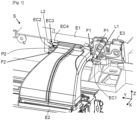
- FIG. 1 a small part of an exemplary embodiment of a system S according to the invention (here a motor vehicle), once the second equipment E2 (here an air intake) is coupled to the first equipment E1 (here an upper crossmember of the front facade of the vehicle S) in the immediate vicinity of a third equipment E3 (here a locking mechanism for the front hood of the vehicle S).
- the second equipment E2 here an air intake
- the first equipment E1 here an upper crossmember of the front facade of the vehicle S
- E3 here a locking mechanism for the front hood of the vehicle S.
- the first E1 equipment is here suitable for being installed transversely (i.e. mainly in the transverse direction Y) in the front part of the S system, at the level of the front facade.
- the first equipment E1 comprises a first coupling element EC1 comprising a first housing L1 open on two adjoining faces, and a second coupling element EC2 comprising a second housing L2 open on two adjoining faces and oriented towards the first housing L1.
- the two open faces of the first housing L1, as of the second housing L2 have normals which are substantially parallel respectively to the vertical Z and transverse Y directions.
- the second equipment E2 comprises first F1 and second F2 opposite faces and provided respectively with first P1 and second P2 projecting walls.
- first face F1 is located on the right and the second face F2 is located on the left (when placed in front of the vehicle S looking towards its rear part).
- the first projecting wall P1 is introduced into the first housing L1 via its two open faces by an oblique translation of the second equipment E2 (materialized by the arrow FL1 of the figure 5 ).
- This oblique translation (arrow FL1) advantageously makes it possible to pass right next to the third equipment E3 without touching it in order to carry out part of the coupling, namely that of the right part of the second equipment E2 (via the first projecting wall P1) to the first coupling element EC1 of the first equipment E1 (via its first housing L1).
- the second projecting wall P2 is introduced into the second housing L2 via its two open faces by a rotation of the second equipment E2 around a virtual axis perpendicular to the first projecting wall P1 (and materialized by the arrows FL2 of the Figures 6 and 7 ).
- This rotation here downwards (arrows FL2), advantageously makes it possible to carry out the other part of the coupling, namely that of the left part of the second equipment E2 (via the second projecting wall P2) to the second coupling element EC2 of the first equipment E1 (via its second housing L2), still without touching the third equipment E3.
- the coupling of the second equipment E2 to the first equipment E1 therefore includes a first translation phase illustrated in the figure 5 and allowing here to pass right next to the third E3 equipment, and a second rotation phase illustrated on the Figures 6 and 7 .
- first translation phase illustrated in the figure 5 and allowing here to pass right next to the third E3 equipment
- second rotation phase illustrated on the Figures 6 and 7 .
- the first coupling element EC1 may be a wall which is partly secured to a front face of the first equipment E1 so as to define between it and this front face the first housing L1, and which may be reinforced by at least one rib.
- the second coupling element EC2 may be another wall which is partly secured to the front face of the first equipment E1 so as to define between it and this front face the second housing L2, and which may be reinforced by at least one rib.
- first EC1 and second EC2 coupling elements can be offset relative to each other.
- first P1 and second P2 projecting walls are also offset relative to each other. This makes it easier to avoid the third equipment E3 during the translation phase.
- the first equipment E1 can advantageously comprise a third coupling element EC3 spaced from the second housing L2 (here upwards).
- the second equipment E2 may comprise a fourth coupling element EC4 spaced from the second projecting wall P2 (here upwards) and cooperating with the third coupling element EC3 to ensure complementary coupling of the second equipment E2 to the first equipment E1.
- the complementary coupling advantageously makes it possible to immobilize the second equipment E2 relative to the first equipment E1 in the vertical direction Z.
- the third coupling element EC3 can be arranged in the form of a protuberance (for example a protruding edge), and the fourth coupling element EC4 can be arranged in the form of a clipping tab clipped onto the protuberance EC3.
- the clipping tab EC4 comprises a head which, once passed beyond (here below) the protuberance EC3, comes to be anchored on the latter (PC3).
- the first equipment E1 can advantageously comprise a third wall P3 located between the first EC1 and second EC2 coupling elements and provided with an opening (or cutout) OV.
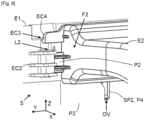
- the second equipment E2 can comprise a fourth projecting wall P4 which is introduced into the opening OV during rotation of the second equipment E2 (see Figures 6 to 8 ).
- This is particularly advantageous because it not only ensures indexing of the positioning of the second equipment E2 relative to the first equipment E1, here following the transverse directions Y and vertical Z, but also guides the second equipment E2 during its rotation.
- the entrance (here upper) of the opening OV is flared (here on the left) in the area where contact is made first with the fourth projecting wall P4.
- the third wall P3 can be preceded (on its rear face) by a passage PP which communicates with the opening OV.
- the fourth projecting wall P4 may comprise first SP1 and second SP2 sub-parts which are perpendicular to each other and introduced respectively into the passage PP and into the opening OV during the rotation of the second equipment E2.
- This is advantageous because it makes it possible to additionally ensure indexing of the positioning of the second equipment E2 relative to the first equipment E1, here in the longitudinal direction X.
- the first sub-part SP1 is substantially in contact with the rear face of the third wall P3, it is certain that the first P1 and second P2 projecting walls are respectively housed in the first L1 and second L2 housings.
Landscapes
- Engineering & Computer Science (AREA)
- Chemical & Material Sciences (AREA)
- Combustion & Propulsion (AREA)
- Transportation (AREA)
- Mechanical Engineering (AREA)
- Casings For Electric Apparatus (AREA)
- Connection Of Plates (AREA)
- Body Structure For Vehicles (AREA)
Description
- L'invention concerne les systèmes qui comprennent deux équipements devant être couplés l'un à l'autre, et plus précisément le couplage de ces deux équipements.
- Certains systèmes, comme par exemple certains véhicules, comprennent un premier équipement auquel est couplé en au moins deux endroits un second équipement. A titre d'exemple purement illustratif un tel système peut être un véhicule, éventuellement automobile, dans lequel le premier équipement est une traverse supérieure d'une façade avant et le second équipement est une prise d'air propre à collecter et canaliser de l'air.
- Le couplage entre les deux équipements se fait généralement par vissage et/ou par clippage au moyen d'au moins deux pattes de clippage, comme décrit dans le document brevet
FR-B1 3018478 - Par ailleurs, le couplage actuel par clippage n'assure généralement une immobilisation que suivant une direction de l'espace (longitudinale ou transversale ou verticale), ce qui peut s'avérer insuffisant dans certains cas.
- Un autre système comprenant un premier équipement auquel est couplé un second équipement est connu du document
WO 2014/140478 A1 . 11 - L'invention a donc notamment pour but d'améliorer la situation.
- Elle propose notamment à cet effet un système selon la revendication 1, comprenant un premier équipement auquel est couplé un second équipement. Le son premier équipement comprend des premier et deuxième éléments de couplage comportant respectivement des premier et second logements ouverts sur deux faces se joignant, et le second équipement comprend deux faces opposées et munies respectivement de première et deuxième parois saillantes, la première paroi saillante étant introduite dans le premier logement via ses deux faces ouvertes par une translation en biais du second équipement, et la deuxième paroi saillante étant introduite dans le second logement via ses deux faces ouvertes par une rotation du second équipement autour d'un axe virtuel perpendiculaire à la première paroi saillante.
- Grâce à ce couplage du second équipement au premier équipement en une phase de translation en biais suivie d'une phase de rotation, le second équipement peut désormais passer juste à côté d'au moins un autre équipement sans toucher ce dernier, ce qui est particulièrement simple et avantageux dans un environnement fortement contraint.
- Le système selon l'invention peut comporter d'autres caractéristiques qui peuvent être prises séparément ou en combinaison, et notamment :
- son premier équipement peut comprendre un troisième élément de couplage espacé du second logement. Dans ce cas, son second équipement peut comprendre un quatrième élément de couplage espacé de la deuxième paroi saillante et coopérant avec le troisième élément de couplage pour assurer un couplage complémentaire du second équipement au premier équipement ;
- en présence de la première option, le troisième élément de couplage peut être agencé sous la forme d'une protubérance, et le quatrième élément de couplage peut être agencé sous la forme d'une patte de clippage qui est clippée sur cette protubérance ;
- son premier équipement peut comprendre une troisième paroi située entre les premier et deuxième éléments de couplage et munie d'une ouverture. Dans ce cas, son second équipement peut comprendre une quatrième paroi saillante introduite dans cette ouverture lors de la rotation du second équipement ;
- en présence de la dernière option, la troisième paroi peut être précédée par un passage communiquant avec l'ouverture. Dans ce cas, la quatrième paroi saillante peut comprendre des première et seconde sous-parties perpendiculaires entre elles et introduites respectivement dans le passage et dans l'ouverture lors de la rotation du second équipement ;
- les premier et deuxième éléments de couplage peuvent être décalés l'un par rapport à l'autre. Dans ce cas, les première et deuxième parois saillantes sont également décalées l'une par rapport à l'autre ;
- il peut constituer un véhicule, éventuellement de type automobile,
- en présence de la dernière option, le premier équipement peut être une traverse supérieure d'une façade avant ;
- également en présence de la dernière option, le second équipement peut être une prise d'air propre à collecter et canaliser de l'air.
- D'autres caractéristiques et avantages de l'invention apparaîtront à l'examen de la description détaillée ci-après, et des dessins annexés (obtenus en CAO/DAO (« Conception Assistée par Ordinateur/Dessin Assisté par Ordinateur »)), sur lesquels :
- [
Fig. 1 ] illustre schématiquement, dans une vue en perspective du côté avant, une petite partie d'un exemple de réalisation d'un système selon l'invention une fois le second équipement couplé au premier équipement, - [
Fig. 2 ] illustre schématiquement, dans une vue en perspective du côté avant, une partie du premier équipement du système de lafigure 1 , avant le couplage du second équipement, - [
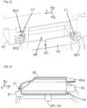
Fig. 3 ] illustre schématiquement, dans une vue de face du côté de la face arrière, le second équipement du système de lafigure 1 , avant son couplage au premier équipement, - [
Fig. 4 ] illustre schématiquement, dans une vue en perspective du côté gauche, une partie gauche du second équipement du système de lafigure 1 , - [
Fig. 5 ] illustre schématiquement, dans une vue en perspective du côté avant, une partie droite du second équipement pendant la phase de translation en biais effectuée lors de son couplage au premier équipement du système de lafigure 1 , - [
Fig. 6 ] illustre schématiquement, dans une vue en perspective du côté avant, une partie gauche du second équipement au début de la phase de rotation effectuée lors de son couplage au premier équipement du système de lafigure 1 , - [
Fig. 7 ] illustre schématiquement, dans une vue en perspective du côté avant, la partie gauche du second équipement à un stade intermédiaire de la phase de rotation effectuée lors de son couplage au premier équipement du système de lafigure 1 , et - [
Fig. 8 ] illustre schématiquement, dans une vue en perspective du côté avant, la partie gauche du second équipement à la fin de la phase de rotation effectuée lors de son couplage au premier équipement du système de lafigure 1 . - L'invention a notamment pour but de proposer un système S comprenant des premier E1 et second E2 équipements couplés entre eux dans un environnement fortement contraint, par exemple du fait de la présence d'au moins un troisième équipement E3.
- Dans ce qui suit, on considère, à titre d'exemple non limitatif, que le système S est un véhicule de type automobile, comme par exemple une voiture. Mais l'invention n'est pas limitée à ce type de système. Elle concerne en effet tout système dans lequel un second équipement doit être couplé à un premier équipement dans un environnement fortement contraint. Par conséquent, le système S pourra être un véhicule de n'importe quel type (terrestre, maritime (ou fluvial), ou aérien), un bâtiment, une installation (éventuellement industrielle), ou un appareil (éventuellement grand public), par exemple.
- Par ailleurs, on considère dans ce qui suit, à titre d'exemple non limitatif, que le premier équipement E1 est une traverse supérieure d'une façade avant du véhicule S, et que le second équipement E2 est une prise d'air propre à collecter et canaliser de l'air pour l'acheminer dans une zone prédéfinie (par exemple près d'une machine motrice ou d'un échangeur de chaleur). Mais l'invention n'est pas limitée à ces types de premier et second équipements.
- En outre, on considère dans ce qui suit, à titre d'exemple non limitatif, que le troisième équipement E3 est un mécanisme de verrouillage d'un capot avant du véhicule S. Mais l'invention n'est pas limitée à ce type de troisième équipement.
- Sur les
figures 1 à 8 la direction X est la direction longitudinale du système (ici un véhicule) S, laquelle est parallèle aux côtés latéraux comportant les portières latérales, la direction Y est la direction transversale du système S, laquelle est perpendiculaire à la direction longitudinale X, et la direction Z est la direction verticale du système S, laquelle est perpendiculaire aux directions longitudinale X et transversale Y. - Dans ce qui suit et ce qui précède les notions « d'avant » et « d'arrière » s'entendent par rapport à l'extrémité avant du véhicule S.
- On a schématiquement illustré sur la
figure 1 une petite partie d'un exemple de réalisation d'un système S selon l'invention (ici un véhicule automobile), une fois le second équipement E2 (ici une prise d'air) couplé au premier équipement E1 (ici une traverse supérieure de la façade avant du véhicule S) à proximité immédiate d'un troisième équipement E3 (ici un mécanisme de verrouillage du capot avant du véhicule S). - Le premier équipement E1 est ici propre à être installé transversalement (c'est-à-dire principalement suivant la direction transversale Y) dans la partie avant du système S, au niveau de la façade avant.
- Comme illustré au moins partiellement sur les
figures 1 ,2 et5 à8 , le premier équipement E1 comprend un premier élément de couplage EC1 comportant un premier logement L1 ouvert sur deux faces se joignant, et un deuxième élément de couplage EC2 comportant un second logement L2 ouvert sur deux faces se joignant et orienté vers le premier logement L1. Ici les deux faces ouvertes du premier logement L1, comme du second logement L2, ont des normales qui sont sensiblement parallèles respectivement aux directions verticale Z et transversale Y. - Comme illustré au moins partiellement sur les
figures 1 et5 à8 , le second équipement E2 comprend des première F1 et seconde F2 faces opposées et munies respectivement de première P1 et deuxième P2 parois saillantes. Ici, la première face F1 est située à droite et la seconde face F2 est située à gauche (lorsque l'on est placé devant le véhicule S en regardant vers sa partie arrière). - La première paroi saillante P1 est introduite dans le premier logement L1 via ses deux faces ouvertes par une translation en biais du second équipement E2 (matérialisée par la flèche FL1 de la
figure 5 ). Cette translation en biais (flèche FL1) permet ici avantageusement de passer juste à côté du troisième équipement E3 sans le toucher afin de réaliser une partie du couplage, à savoir celui de la partie droite du second équipement E2 (via la première paroi saillante P1) au premier élément de couplage EC1 du premier équipement E1 (via son premier logement L1). - Une fois la première paroi saillante P1 introduite dans le premier logement L1, la deuxième paroi saillante P2 est introduite dans le second logement L2 via ses deux faces ouvertes par une rotation du second équipement E2 autour d'un axe virtuel perpendiculaire à la première paroi saillante P1 (et matérialisée par les flèches FL2 des
figures 6 et 7 ). Cette rotation, ici vers le bas (flèches FL2), permet avantageusement de réaliser l'autre partie du couplage, à savoir celui de la partie gauche du second équipement E2 (via la deuxième paroi saillante P2) au deuxième élément de couplage EC2 du premier équipement E1 (via son second logement L2), toujours sans toucher le troisième équipement E3. - Le couplage du second équipement E2 au premier équipement E1 comprend donc une première phase de translation illustrée sur la
figure 5 et permettant ici de passer juste à côté du troisième équipement E3, et une seconde phase de rotation illustrée sur lesfigures 6 et 7 . Une fois le couplage terminé (translation en biais (FL1) plus rotation (FL2)) on dispose d'un assemblage de premier E1 et second E2 équipements couplés, illustré au moins partiellement sur lesfigures 1 et8 . Dans l'exemple illustré, le couplage permet avantageusement d'immobiliser le second équipement E2 par rapport au premier équipement E1 suivant les directions transversale X et longitudinale Y, du fait des logements des première L1 et deuxième L2 parois saillantes respectivement dans les premier L1 et second L2 logements (partiellement ouverts). - Par exemple, et comme illustré non limitativement sur les
figures 1 ,2 et5 , le premier élément de couplage EC1 peut être une paroi qui est en partie solidarisée à une face avant du premier équipement E1 de manière à définir entre elle et cette face avant le premier logement L1, et qui peut être renforcée par au moins une nervure. - Egalement par exemple, et comme illustré non limitativement sur les
figures 1 ,2 et6 à8 , le deuxième élément de couplage EC2 peut être une autre paroi qui est en partie solidarisée à la face avant du premier équipement E1 de manière à définir entre elle et cette face avant le second logement L2, et qui peut être renforcée par au moins une nervure. - On notera, comme illustré non limitativement et au moins partiellement sur les
figures 1 à 3 , que les premier EC1 et deuxième EC2 éléments de couplage peuvent être décalés l'un par rapport à l'autre. Dans ce cas les première P1 et deuxième P2 parois saillantes sont également décalées l'une par rapport à l'autre. Cela permet de faciliter l'évitement du troisième équipement E3 pendant la phase de translation. - Egalement par exemple, et comme illustré non limitativement sur les
figures 1 ,2 et6 à8 , le premier équipement E1 peut avantageusement comprendre un troisième élément de couplage EC3 espacé du second logement L2 (ici vers le haut). Dans ce cas, et comme illustré non limitativement sur lesfigures 1 ,3 ,4 et6 à8 , le second équipement E2 peut comprendre un quatrième élément de couplage EC4 espacé de la deuxième paroi saillante P2 (ici vers le haut) et coopérant avec le troisième élément de couplage EC3 pour assurer un couplage complémentaire du second équipement E2 au premier équipement E1. Dans l'exemple illustré, le couplage complémentaire permet avantageusement d'immobiliser le second équipement E2 par rapport au premier équipement E1 suivant la direction verticale Z. - A titre d'exemple, et comme illustré non limitativement et au moins partiellement sur les
figures 2 à 8 , le troisième élément de couplage EC3 peut être agencé sous la forme d'une protubérance (par exemple un bord saillant), et le quatrième élément de couplage EC4 peut être agencé sous la forme d'une patte de clippage clippée sur la protubérance EC3. On comprendra que la patte de clippage EC4 comprend une tête qui, une fois passée au-delà (ici en-dessous) de la protubérance EC3, vient s'ancrer sur cette dernière (PC3). - On notera qu'un agencement inverse peut être envisagé, à savoir un quatrième élément de couplage EC4 agencé sous la forme d'une protubérance, et un troisième élément de couplage EC3 agencé sous la forme d'une patte de clippage clippée sur la protubérance EC4.
- On notera également, comme illustré non limitativement et au moins partiellement sur les
figures 2, 3 et6 à8 , que le premier équipement E1 peut avantageusement comprendre une troisième paroi P3 située entre les premier EC1 et deuxième EC2 éléments de couplage et munie d'une ouverture (ou découpe) OV. Dans ce cas, le second équipement E2 peut comprendre une quatrième paroi saillante P4 qui est introduite dans l'ouverture OV lors de la rotation du second équipement E2 (voirfigures 6 à 8 ). Cela est particulièrement avantageux car cela permet non seulement d'assurer une indexation du positionnement du second équipement E2 par rapport au premier équipement E1, ici suivant les directions transversale Y et verticale Z, mais aussi de guider le second équipement E2 pendant sa rotation. Afin de renforcer cette fonction de guidage, il est avantageux, comme illustré non limitativement, que l'entrée (ici supérieure) de l'ouverture OV soit évasée (ici sur la gauche) dans la zone où le contact se fait en premier avec la quatrième paroi saillante P4. - Par exemple, et comme illustré non limitativement et au moins partiellement sur les
figures 2, 3 et6 à8 , la troisième paroi P3 peut être précédée (du côté de sa face arrière) par un passage PP qui communique avec l'ouverture OV. - Dans ce cas, la quatrième paroi saillante P4 peut comprendre des première SP1 et seconde SP2 sous-parties qui sont perpendiculaires entre elles et introduites respectivement dans le passage PP et dans l'ouverture OV lors de la rotation du second équipement E2. Cela est avantageux car cela permet d'assurer en complément une indexation du positionnement du second équipement E2 par rapport au premier équipement E1, ici suivant la direction longitudinale X. En effet, lorsque la première sous-partie SP1 est sensiblement au contact de la face arrière de la troisième paroi P3, on est certain que les première P1 et deuxième P2 parois saillantes sont respectivement logées dans les premier L1 et second L2 logements.
Claims (10)
- Système (S) comprenant un premier équipement (E1) auquel est couplé un second équipement (E2), ledit premier équipement (E1) comprenant des premier (EC1) et deuxième (EC2) éléments de couplage comportant respectivement des premier (L1) et second (L2) logements ouverts sur deux faces se joignant, caractérisé en ce que ledit second équipement (E2) comprend deux faces (F1, F2) opposées et munies respectivement de première (P1) et deuxième (P2) parois saillantes, ladite première paroi saillante (P1) étant introduite dans ledit premier logement (L1) via ses deux faces ouvertes par une translation en biais dudit second équipement (E2), et ladite deuxième paroi saillante (P2) étant introduite dans ledit second logement (L2) via ses deux faces ouvertes par une rotation dudit second équipement (E2) autour d'un axe virtuel perpendiculaire à ladite première paroi saillante (P1).
- Système selon la revendication 1, caractérisé en ce que ledit premier équipement (E1) comprend un troisième élément de couplage (EC3) espacé dudit second logement (L2), et en ce que ledit second équipement (E2) comprend un quatrième élément de couplage (EC4) espacé de ladite deuxième paroi saillante (P2) et coopérant avec ledit troisième élément de couplage (EC3) pour assurer un couplage complémentaire dudit second équipement (E2) audit premier équipement (E1).
- Système selon la revendication 2, caractérisé en ce que ledit troisième élément de couplage (EC3) est agencé sous la forme d'une protubérance, et ledit quatrième élément de couplage (EC4) est agencé sous la forme d'une patte de clippage clippée sur ladite protubérance (EC3).
- Système selon l'une des revendications 1 à 3, caractérisé en ce que ledit premier équipement (E1) comprend une troisième paroi (P3) située entre lesdits premier (EC1) et deuxième (EC2) éléments de couplage et munie d'une ouverture (OV), et en ce que ledit second équipement (E2) comprend une quatrième paroi saillante (P4) introduite dans ladite ouverture (OV) lors de ladite rotation du second équipement (E2).
- Système selon la revendication 4, caractérisé en ce que ladite troisième paroi (P3) est précédée par un passage (PP) communiquant avec ladite ouverture (OV), et en ce que ladite quatrième paroi saillante (P4) comprend des première (SP1) et seconde (SP2) sous-parties perpendiculaires entre elles et introduites respectivement dans ledit passage (PP) et dans ladite ouverture (OV) lors de ladite rotation du second équipement (E2).
- Système selon l'une des revendications 1 à 5, caractérisé en ce que lesdits premier (EC1) et deuxième (EC2) éléments de couplage sont décalés l'un par rapport à l'autre, et lesdites première (P1) et deuxième (P2) parois saillantes sont décalées l'une par rapport à l'autre.
- Système selon l'une des revendications 1 à 6, caractérisé en ce qu'il constitue un véhicule.
- Système selon la revendication 7, caractérisé en ce que ledit premier équipement (E1) est une traverse supérieure d'une façade avant.
- Système selon la revendication 7 ou 8, caractérisé en ce que ledit second équipement (E2) est une prise d'air propre à collecter et canaliser de l'air.
- Système selon l'une des revendications 7 à 9, caractérisé en ce qu'il constitue un véhicule automobile.
Applications Claiming Priority (2)
| Application Number | Priority Date | Filing Date | Title |
|---|---|---|---|
| FR2105563A FR3123301B1 (fr) | 2021-05-28 | 2021-05-28 | Couplage d’équipements d’un système dans un environnement fortement contraint |
| PCT/FR2022/050786 WO2022248787A1 (fr) | 2021-05-28 | 2022-04-26 | Couplage d'équipements d'un système dans un environnement fortement contraint |
Publications (2)
| Publication Number | Publication Date |
|---|---|
| EP4347296A1 EP4347296A1 (fr) | 2024-04-10 |
| EP4347296B1 true EP4347296B1 (fr) | 2025-02-19 |
Family
ID=76920935
Family Applications (1)
| Application Number | Title | Priority Date | Filing Date |
|---|---|---|---|
| EP22735531.0A Active EP4347296B1 (fr) | 2021-05-28 | 2022-04-26 | Couplage d'équipements d'un système dans un environnement fortement contraint |
Country Status (3)
| Country | Link |
|---|---|
| EP (1) | EP4347296B1 (fr) |
| FR (1) | FR3123301B1 (fr) |
| WO (1) | WO2022248787A1 (fr) |
Family Cites Families (5)
| Publication number | Priority date | Publication date | Assignee | Title |
|---|---|---|---|---|
| FR2105563A5 (en) | 1970-09-11 | 1972-04-28 | Universal Oil Prod Co | Synergistic antiozonant mixture for rubber - comprising aromatic p-phenylenediamines |
| FR3003207B1 (fr) * | 2013-03-14 | 2015-03-13 | Renault Sa | "valise de refroidissement comportant des moyens de rattrapage des dispersions de fabrication" |
| FR3018478B1 (fr) | 2014-03-17 | 2016-03-11 | Renault Sas | Assemblage d'un guide d'air a un element structurel de vehicule automobile et vehicule correspondant |
| WO2017002146A1 (fr) * | 2015-06-30 | 2017-01-05 | 本田技研工業株式会社 | Structure de fixation pour conduit d'admission de véhicule automobile |
| DE102015118726A1 (de) * | 2015-11-02 | 2017-05-04 | Dr. Ing. H.C. F. Porsche Aktiengesellschaft | Luftführungsvorrichtung für ein Fahrzeug |
-
2021
- 2021-05-28 FR FR2105563A patent/FR3123301B1/fr active Active
-
2022
- 2022-04-26 WO PCT/FR2022/050786 patent/WO2022248787A1/fr not_active Ceased
- 2022-04-26 EP EP22735531.0A patent/EP4347296B1/fr active Active
Also Published As
| Publication number | Publication date |
|---|---|
| FR3123301B1 (fr) | 2023-04-14 |
| FR3123301A1 (fr) | 2022-12-02 |
| EP4347296A1 (fr) | 2024-04-10 |
| WO2022248787A1 (fr) | 2022-12-01 |
Similar Documents
| Publication | Publication Date | Title |
|---|---|---|
| FR3125272A1 (fr) | Déflecteur aérodynamique destiné à être fixé contre le soubassement de caisse d’un véhicule automobile et pourvu de moyens de pré-maintien | |
| EP4347296B1 (fr) | Couplage d'équipements d'un système dans un environnement fortement contraint | |
| WO2017089720A1 (fr) | Dispositif de montage d'un radar pour véhicule automobile | |
| EP2922730B1 (fr) | Agencement d'une façade avant d'un véhicule automobile pourvu d'une grille d'entrée d'air fixée au bouclier avant par un verrouillage extérieur | |
| EP3165059B1 (fr) | Ensemble de fixation d'un boitier electronique et vehicule equipe d'un tel ensemble | |
| EP2870056B1 (fr) | Traverse inferieure de baie de pare-brise etanche au bruit | |
| EP4135997B1 (fr) | Traverse supérieure de bloc avant pour véhicule automobile | |
| FR3099907A1 (fr) | Déflecteur aérodynamique arrière pour véhicule automobile | |
| FR3134859A1 (fr) | Équipement à pièce adaptée au clippage double | |
| FR3063126B1 (fr) | Protection pour gaine de conducteur electrique ou de fluide de vehicule automobile | |
| EP3898390A1 (fr) | Elément d'habitacle pour véhicule automobile et ensemble comprenant un tel élément d'habitacle | |
| WO2008017774A1 (fr) | Ouvrant de vehicule automobile comprenant un raidisseur et vehicule muni un tel ouvrant | |
| WO2024115828A1 (fr) | Véhicule comportant un coffre à éléments de fixation de supports de panneau de support invisibles | |
| FR2937926A1 (fr) | Support multifonction pour vehicule automobile. | |
| EP3658417B1 (fr) | Clip de pre maintien avec jeu fonctionnel | |
| FR3040677A1 (fr) | Agencement d'un passage de roue d'un vehicule automobile | |
| EP3254903B1 (fr) | Piece de fixation d'elements d'habillage sur un element de structure lateral de vehicule automobile | |
| FR3132872A1 (fr) | Pièce d’interface pour l’étanchéité entre un équipement et une grille d’entrée d’air d’un pare-chocs de véhicule terrestre | |
| FR3138172A1 (fr) | Équipement à double clip, pour un système | |
| FR3143488A1 (fr) | Support de plancher intermédiaire d’un coffre de véhicule automobile, coffre de véhicule automobile et véhicule automobile comportant un tel coffre | |
| WO2024069064A1 (fr) | Pièce de renfort pour une partie avant supérieure à bords repliés d'une aile de véhicule automobile | |
| WO2015007968A1 (fr) | Dispositif de maintien de cable(s) et de support d'un boitier de commande, pour la traversee d'un ouverture definie dans un equipement lors du montage du boitier de commande sur ledit equipement | |
| FR3139784A1 (fr) | Armature de pare-chocs à joint à appui renforcé pour un véhicule | |
| FR3132678A1 (fr) | Face avant de véhicule pourvue de lames flexibles formant un absorbeur de pare-chocs. | |
| WO2014019773A1 (fr) | Attache élastique, dispositif d'attache et procédé de fabrication correspondant |
Legal Events
| Date | Code | Title | Description |
|---|---|---|---|
| STAA | Information on the status of an ep patent application or granted ep patent |
Free format text: STATUS: UNKNOWN |
|
| STAA | Information on the status of an ep patent application or granted ep patent |
Free format text: STATUS: THE INTERNATIONAL PUBLICATION HAS BEEN MADE |
|
| PUAI | Public reference made under article 153(3) epc to a published international application that has entered the european phase |
Free format text: ORIGINAL CODE: 0009012 |
|
| STAA | Information on the status of an ep patent application or granted ep patent |
Free format text: STATUS: REQUEST FOR EXAMINATION WAS MADE |
|
| 17P | Request for examination filed |
Effective date: 20231211 |
|
| AK | Designated contracting states |
Kind code of ref document: A1 Designated state(s): AL AT BE BG CH CY CZ DE DK EE ES FI FR GB GR HR HU IE IS IT LI LT LU LV MC MK MT NL NO PL PT RO RS SE SI SK SM TR |
|
| DAV | Request for validation of the european patent (deleted) | ||
| DAX | Request for extension of the european patent (deleted) | ||
| GRAP | Despatch of communication of intention to grant a patent |
Free format text: ORIGINAL CODE: EPIDOSNIGR1 |
|
| STAA | Information on the status of an ep patent application or granted ep patent |
Free format text: STATUS: GRANT OF PATENT IS INTENDED |
|
| INTG | Intention to grant announced |
Effective date: 20240920 |
|
| GRAS | Grant fee paid |
Free format text: ORIGINAL CODE: EPIDOSNIGR3 |
|
| GRAA | (expected) grant |
Free format text: ORIGINAL CODE: 0009210 |
|
| STAA | Information on the status of an ep patent application or granted ep patent |
Free format text: STATUS: THE PATENT HAS BEEN GRANTED |
|
| AK | Designated contracting states |
Kind code of ref document: B1 Designated state(s): AL AT BE BG CH CY CZ DE DK EE ES FI FR GB GR HR HU IE IS IT LI LT LU LV MC MK MT NL NO PL PT RO RS SE SI SK SM TR |
|
| REG | Reference to a national code |
Ref country code: GB Ref legal event code: FG4D Free format text: NOT ENGLISH |
|
| REG | Reference to a national code |
Ref country code: CH Ref legal event code: EP |
|
| REG | Reference to a national code |
Ref country code: DE Ref legal event code: R096 Ref document number: 602022010898 Country of ref document: DE |
|
| REG | Reference to a national code |
Ref country code: IE Ref legal event code: FG4D Free format text: LANGUAGE OF EP DOCUMENT: FRENCH |
|
| REG | Reference to a national code |
Ref country code: DE Ref legal event code: R084 Ref document number: 602022010898 Country of ref document: DE |
|
| REG | Reference to a national code |
Ref country code: NL Ref legal event code: MP Effective date: 20250219 |
|
| PG25 | Lapsed in a contracting state [announced via postgrant information from national office to epo] |
Ref country code: RS Free format text: LAPSE BECAUSE OF FAILURE TO SUBMIT A TRANSLATION OF THE DESCRIPTION OR TO PAY THE FEE WITHIN THE PRESCRIBED TIME-LIMIT Effective date: 20250519 |
|
| PG25 | Lapsed in a contracting state [announced via postgrant information from national office to epo] |
Ref country code: FI Free format text: LAPSE BECAUSE OF FAILURE TO SUBMIT A TRANSLATION OF THE DESCRIPTION OR TO PAY THE FEE WITHIN THE PRESCRIBED TIME-LIMIT Effective date: 20250219 |
|
| PG25 | Lapsed in a contracting state [announced via postgrant information from national office to epo] |
Ref country code: PL Free format text: LAPSE BECAUSE OF FAILURE TO SUBMIT A TRANSLATION OF THE DESCRIPTION OR TO PAY THE FEE WITHIN THE PRESCRIBED TIME-LIMIT Effective date: 20250219 |
|
| PGFP | Annual fee paid to national office [announced via postgrant information from national office to epo] |
Ref country code: DE Payment date: 20250319 Year of fee payment: 4 |
|
| PG25 | Lapsed in a contracting state [announced via postgrant information from national office to epo] |
Ref country code: ES Free format text: LAPSE BECAUSE OF FAILURE TO SUBMIT A TRANSLATION OF THE DESCRIPTION OR TO PAY THE FEE WITHIN THE PRESCRIBED TIME-LIMIT Effective date: 20250219 |
|
| REG | Reference to a national code |
Ref country code: LT Ref legal event code: MG9D |
|
| PG25 | Lapsed in a contracting state [announced via postgrant information from national office to epo] |
Ref country code: IS Free format text: LAPSE BECAUSE OF FAILURE TO SUBMIT A TRANSLATION OF THE DESCRIPTION OR TO PAY THE FEE WITHIN THE PRESCRIBED TIME-LIMIT Effective date: 20250619 Ref country code: NO Free format text: LAPSE BECAUSE OF FAILURE TO SUBMIT A TRANSLATION OF THE DESCRIPTION OR TO PAY THE FEE WITHIN THE PRESCRIBED TIME-LIMIT Effective date: 20250519 |
|
| PG25 | Lapsed in a contracting state [announced via postgrant information from national office to epo] |
Ref country code: NL Free format text: LAPSE BECAUSE OF FAILURE TO SUBMIT A TRANSLATION OF THE DESCRIPTION OR TO PAY THE FEE WITHIN THE PRESCRIBED TIME-LIMIT Effective date: 20250219 |
|
| PG25 | Lapsed in a contracting state [announced via postgrant information from national office to epo] |
Ref country code: HR Free format text: LAPSE BECAUSE OF FAILURE TO SUBMIT A TRANSLATION OF THE DESCRIPTION OR TO PAY THE FEE WITHIN THE PRESCRIBED TIME-LIMIT Effective date: 20250219 |
|
| PG25 | Lapsed in a contracting state [announced via postgrant information from national office to epo] |
Ref country code: LV Free format text: LAPSE BECAUSE OF FAILURE TO SUBMIT A TRANSLATION OF THE DESCRIPTION OR TO PAY THE FEE WITHIN THE PRESCRIBED TIME-LIMIT Effective date: 20250219 Ref country code: PT Free format text: LAPSE BECAUSE OF FAILURE TO SUBMIT A TRANSLATION OF THE DESCRIPTION OR TO PAY THE FEE WITHIN THE PRESCRIBED TIME-LIMIT Effective date: 20250620 |
|
| PG25 | Lapsed in a contracting state [announced via postgrant information from national office to epo] |
Ref country code: BG Free format text: LAPSE BECAUSE OF FAILURE TO SUBMIT A TRANSLATION OF THE DESCRIPTION OR TO PAY THE FEE WITHIN THE PRESCRIBED TIME-LIMIT Effective date: 20250219 Ref country code: GR Free format text: LAPSE BECAUSE OF FAILURE TO SUBMIT A TRANSLATION OF THE DESCRIPTION OR TO PAY THE FEE WITHIN THE PRESCRIBED TIME-LIMIT Effective date: 20250520 |
|
| REG | Reference to a national code |
Ref country code: AT Ref legal event code: MK05 Ref document number: 1768000 Country of ref document: AT Kind code of ref document: T Effective date: 20250219 |
|
| PG25 | Lapsed in a contracting state [announced via postgrant information from national office to epo] |
Ref country code: SE Free format text: LAPSE BECAUSE OF FAILURE TO SUBMIT A TRANSLATION OF THE DESCRIPTION OR TO PAY THE FEE WITHIN THE PRESCRIBED TIME-LIMIT Effective date: 20250219 |
|
| PG25 | Lapsed in a contracting state [announced via postgrant information from national office to epo] |
Ref country code: SM Free format text: LAPSE BECAUSE OF FAILURE TO SUBMIT A TRANSLATION OF THE DESCRIPTION OR TO PAY THE FEE WITHIN THE PRESCRIBED TIME-LIMIT Effective date: 20250219 |
|
| PG25 | Lapsed in a contracting state [announced via postgrant information from national office to epo] |
Ref country code: DK Free format text: LAPSE BECAUSE OF FAILURE TO SUBMIT A TRANSLATION OF THE DESCRIPTION OR TO PAY THE FEE WITHIN THE PRESCRIBED TIME-LIMIT Effective date: 20250219 |
|
| PG25 | Lapsed in a contracting state [announced via postgrant information from national office to epo] |
Ref country code: IT Free format text: LAPSE BECAUSE OF FAILURE TO SUBMIT A TRANSLATION OF THE DESCRIPTION OR TO PAY THE FEE WITHIN THE PRESCRIBED TIME-LIMIT Effective date: 20250219 |
|
| PG25 | Lapsed in a contracting state [announced via postgrant information from national office to epo] |
Ref country code: AT Free format text: LAPSE BECAUSE OF FAILURE TO SUBMIT A TRANSLATION OF THE DESCRIPTION OR TO PAY THE FEE WITHIN THE PRESCRIBED TIME-LIMIT Effective date: 20250219 |
|
| PG25 | Lapsed in a contracting state [announced via postgrant information from national office to epo] |
Ref country code: EE Free format text: LAPSE BECAUSE OF FAILURE TO SUBMIT A TRANSLATION OF THE DESCRIPTION OR TO PAY THE FEE WITHIN THE PRESCRIBED TIME-LIMIT Effective date: 20250219 Ref country code: CZ Free format text: LAPSE BECAUSE OF FAILURE TO SUBMIT A TRANSLATION OF THE DESCRIPTION OR TO PAY THE FEE WITHIN THE PRESCRIBED TIME-LIMIT Effective date: 20250219 |
|
| PG25 | Lapsed in a contracting state [announced via postgrant information from national office to epo] |
Ref country code: RO Free format text: LAPSE BECAUSE OF FAILURE TO SUBMIT A TRANSLATION OF THE DESCRIPTION OR TO PAY THE FEE WITHIN THE PRESCRIBED TIME-LIMIT Effective date: 20250219 |
|
| PG25 | Lapsed in a contracting state [announced via postgrant information from national office to epo] |
Ref country code: SK Free format text: LAPSE BECAUSE OF FAILURE TO SUBMIT A TRANSLATION OF THE DESCRIPTION OR TO PAY THE FEE WITHIN THE PRESCRIBED TIME-LIMIT Effective date: 20250219 |
|
| REG | Reference to a national code |
Ref country code: DE Ref legal event code: R097 Ref document number: 602022010898 Country of ref document: DE |
|
| REG | Reference to a national code |
Ref country code: CH Ref legal event code: H13 Free format text: ST27 STATUS EVENT CODE: U-0-0-H10-H13 (AS PROVIDED BY THE NATIONAL OFFICE) Effective date: 20251125 |
|
| PG25 | Lapsed in a contracting state [announced via postgrant information from national office to epo] |
Ref country code: LU Free format text: LAPSE BECAUSE OF NON-PAYMENT OF DUE FEES Effective date: 20250426 |
|
| PG25 | Lapsed in a contracting state [announced via postgrant information from national office to epo] |
Ref country code: MC Free format text: LAPSE BECAUSE OF FAILURE TO SUBMIT A TRANSLATION OF THE DESCRIPTION OR TO PAY THE FEE WITHIN THE PRESCRIBED TIME-LIMIT Effective date: 20250219 |
|
| PLBE | No opposition filed within time limit |
Free format text: ORIGINAL CODE: 0009261 |
|
| STAA | Information on the status of an ep patent application or granted ep patent |
Free format text: STATUS: NO OPPOSITION FILED WITHIN TIME LIMIT |
|
| REG | Reference to a national code |
Ref country code: BE Ref legal event code: MM Effective date: 20250430 |
|
| PG25 | Lapsed in a contracting state [announced via postgrant information from national office to epo] |
Ref country code: BE Free format text: LAPSE BECAUSE OF NON-PAYMENT OF DUE FEES Effective date: 20250430 |
|
| PG25 | Lapsed in a contracting state [announced via postgrant information from national office to epo] |
Ref country code: CH Free format text: LAPSE BECAUSE OF NON-PAYMENT OF DUE FEES Effective date: 20250430 |
|
| 26N | No opposition filed |
Effective date: 20251120 |
|
| PG25 | Lapsed in a contracting state [announced via postgrant information from national office to epo] |
Ref country code: IE Free format text: LAPSE BECAUSE OF NON-PAYMENT OF DUE FEES Effective date: 20250426 |
|
| PGFP | Annual fee paid to national office [announced via postgrant information from national office to epo] |
Ref country code: FR Payment date: 20260320 Year of fee payment: 5 |