EP4343796A1 - Gewickelter kern und verfahren zur herstellung eines gewickelten kerns - Google Patents
Gewickelter kern und verfahren zur herstellung eines gewickelten kerns Download PDFInfo
- Publication number
- EP4343796A1 EP4343796A1 EP22849032.2A EP22849032A EP4343796A1 EP 4343796 A1 EP4343796 A1 EP 4343796A1 EP 22849032 A EP22849032 A EP 22849032A EP 4343796 A1 EP4343796 A1 EP 4343796A1
- Authority
- EP
- European Patent Office
- Prior art keywords
- iron loss
- steel sheet
- length
- grain
- magnetic flux
- Prior art date
- Legal status (The legal status is an assumption and is not a legal conclusion. Google has not performed a legal analysis and makes no representation as to the accuracy of the status listed.)
- Pending
Links
- 238000004519 manufacturing process Methods 0.000 title claims description 17
- XEEYBQQBJWHFJM-UHFFFAOYSA-N Iron Chemical compound [Fe] XEEYBQQBJWHFJM-UHFFFAOYSA-N 0.000 claims abstract description 393
- 229910052742 iron Inorganic materials 0.000 claims abstract description 148
- 230000004907 flux Effects 0.000 claims abstract description 105
- 229910001224 Grain-oriented electrical steel Inorganic materials 0.000 claims abstract description 60
- 239000000463 material Substances 0.000 claims abstract description 33
- 230000006866 deterioration Effects 0.000 claims abstract description 32
- 230000005381 magnetic domain Effects 0.000 claims description 62
- 238000007670 refining Methods 0.000 claims description 59
- 230000005284 excitation Effects 0.000 claims description 19
- 230000005415 magnetization Effects 0.000 claims description 10
- 239000011162 core material Substances 0.000 description 97
- 229910000831 Steel Inorganic materials 0.000 description 52
- 239000010959 steel Substances 0.000 description 52
- 238000000137 annealing Methods 0.000 description 38
- 230000000052 comparative effect Effects 0.000 description 28
- 238000000034 method Methods 0.000 description 22
- 238000004804 winding Methods 0.000 description 20
- 239000011248 coating agent Substances 0.000 description 14
- 238000000576 coating method Methods 0.000 description 14
- 230000007423 decrease Effects 0.000 description 10
- 230000000694 effects Effects 0.000 description 9
- 238000001953 recrystallisation Methods 0.000 description 8
- 238000013461 design Methods 0.000 description 7
- 238000012360 testing method Methods 0.000 description 7
- 229910000976 Electrical steel Inorganic materials 0.000 description 6
- 238000010438 heat treatment Methods 0.000 description 5
- 238000005096 rolling process Methods 0.000 description 5
- VYPSYNLAJGMNEJ-UHFFFAOYSA-N Silicium dioxide Chemical compound O=[Si]=O VYPSYNLAJGMNEJ-UHFFFAOYSA-N 0.000 description 4
- 229910052782 aluminium Inorganic materials 0.000 description 4
- 239000010949 copper Substances 0.000 description 4
- 238000005098 hot rolling Methods 0.000 description 4
- 239000003112 inhibitor Substances 0.000 description 4
- 239000000203 mixture Substances 0.000 description 4
- 229910052757 nitrogen Inorganic materials 0.000 description 4
- 230000035699 permeability Effects 0.000 description 4
- 238000012545 processing Methods 0.000 description 4
- 229910052711 selenium Inorganic materials 0.000 description 4
- 239000000126 substance Substances 0.000 description 4
- 238000005452 bending Methods 0.000 description 3
- 229910052802 copper Inorganic materials 0.000 description 3
- 239000013078 crystal Substances 0.000 description 3
- 238000005261 decarburization Methods 0.000 description 3
- 230000003247 decreasing effect Effects 0.000 description 3
- 229910052839 forsterite Inorganic materials 0.000 description 3
- 239000012535 impurity Substances 0.000 description 3
- 238000011835 investigation Methods 0.000 description 3
- HCWCAKKEBCNQJP-UHFFFAOYSA-N magnesium orthosilicate Chemical compound [Mg+2].[Mg+2].[O-][Si]([O-])([O-])[O-] HCWCAKKEBCNQJP-UHFFFAOYSA-N 0.000 description 3
- 230000001603 reducing effect Effects 0.000 description 3
- 229910052717 sulfur Inorganic materials 0.000 description 3
- 229910052787 antimony Inorganic materials 0.000 description 2
- 230000015572 biosynthetic process Effects 0.000 description 2
- 238000005524 ceramic coating Methods 0.000 description 2
- 238000011161 development Methods 0.000 description 2
- 230000018109 developmental process Effects 0.000 description 2
- 238000009826 distribution Methods 0.000 description 2
- 238000011156 evaluation Methods 0.000 description 2
- 230000001678 irradiating effect Effects 0.000 description 2
- 238000003475 lamination Methods 0.000 description 2
- 239000000696 magnetic material Substances 0.000 description 2
- 238000005259 measurement Methods 0.000 description 2
- 229910052750 molybdenum Inorganic materials 0.000 description 2
- 229910052698 phosphorus Inorganic materials 0.000 description 2
- 238000000053 physical method Methods 0.000 description 2
- 229920006395 saturated elastomer Polymers 0.000 description 2
- 239000000377 silicon dioxide Substances 0.000 description 2
- 229910052718 tin Inorganic materials 0.000 description 2
- RYGMFSIKBFXOCR-UHFFFAOYSA-N Copper Chemical compound [Cu] RYGMFSIKBFXOCR-UHFFFAOYSA-N 0.000 description 1
- 229910001208 Crucible steel Inorganic materials 0.000 description 1
- 238000009825 accumulation Methods 0.000 description 1
- 239000000654 additive Substances 0.000 description 1
- 230000000996 additive effect Effects 0.000 description 1
- 230000032683 aging Effects 0.000 description 1
- 238000013459 approach Methods 0.000 description 1
- 230000008901 benefit Effects 0.000 description 1
- 238000005266 casting Methods 0.000 description 1
- 238000005229 chemical vapour deposition Methods 0.000 description 1
- 238000005097 cold rolling Methods 0.000 description 1
- 238000002425 crystallisation Methods 0.000 description 1
- 230000008025 crystallization Effects 0.000 description 1
- 230000006378 damage Effects 0.000 description 1
- 230000003111 delayed effect Effects 0.000 description 1
- 238000010894 electron beam technology Methods 0.000 description 1
- 238000005530 etching Methods 0.000 description 1
- 239000011521 glass Substances 0.000 description 1
- 229910052748 manganese Inorganic materials 0.000 description 1
- 230000001590 oxidative effect Effects 0.000 description 1
- 238000005240 physical vapour deposition Methods 0.000 description 1
- 230000009467 reduction Effects 0.000 description 1
- 238000010008 shearing Methods 0.000 description 1
- 239000001394 sodium malate Substances 0.000 description 1
- 230000035882 stress Effects 0.000 description 1
- 239000000758 substrate Substances 0.000 description 1
- 239000002344 surface layer Substances 0.000 description 1
- 238000012546 transfer Methods 0.000 description 1
Images


Classifications
-
- H—ELECTRICITY
- H01—ELECTRIC ELEMENTS
- H01F—MAGNETS; INDUCTANCES; TRANSFORMERS; SELECTION OF MATERIALS FOR THEIR MAGNETIC PROPERTIES
- H01F27/00—Details of transformers or inductances, in general
- H01F27/24—Magnetic cores
- H01F27/245—Magnetic cores made from sheets, e.g. grain-oriented
-
- C—CHEMISTRY; METALLURGY
- C21—METALLURGY OF IRON
- C21D—MODIFYING THE PHYSICAL STRUCTURE OF FERROUS METALS; GENERAL DEVICES FOR HEAT TREATMENT OF FERROUS OR NON-FERROUS METALS OR ALLOYS; MAKING METAL MALLEABLE, e.g. BY DECARBURISATION OR TEMPERING
- C21D8/00—Modifying the physical properties by deformation combined with, or followed by, heat treatment
- C21D8/12—Modifying the physical properties by deformation combined with, or followed by, heat treatment during manufacturing of articles with special electromagnetic properties
-
- H—ELECTRICITY
- H01—ELECTRIC ELEMENTS
- H01F—MAGNETS; INDUCTANCES; TRANSFORMERS; SELECTION OF MATERIALS FOR THEIR MAGNETIC PROPERTIES
- H01F27/00—Details of transformers or inductances, in general
- H01F27/24—Magnetic cores
- H01F27/245—Magnetic cores made from sheets, e.g. grain-oriented
- H01F27/2455—Magnetic cores made from sheets, e.g. grain-oriented using bent laminations
-
- H—ELECTRICITY
- H01—ELECTRIC ELEMENTS
- H01F—MAGNETS; INDUCTANCES; TRANSFORMERS; SELECTION OF MATERIALS FOR THEIR MAGNETIC PROPERTIES
- H01F3/00—Cores, Yokes, or armatures
- H01F3/02—Cores, Yokes, or armatures made from sheets
-
- H—ELECTRICITY
- H01—ELECTRIC ELEMENTS
- H01F—MAGNETS; INDUCTANCES; TRANSFORMERS; SELECTION OF MATERIALS FOR THEIR MAGNETIC PROPERTIES
- H01F41/00—Apparatus or processes specially adapted for manufacturing or assembling magnets, inductances or transformers; Apparatus or processes specially adapted for manufacturing materials characterised by their magnetic properties
- H01F41/02—Apparatus or processes specially adapted for manufacturing or assembling magnets, inductances or transformers; Apparatus or processes specially adapted for manufacturing materials characterised by their magnetic properties for manufacturing cores, coils, or magnets
- H01F41/0206—Manufacturing of magnetic cores by mechanical means
- H01F41/0233—Manufacturing of magnetic circuits made from sheets
- H01F41/024—Manufacturing of magnetic circuits made from deformed sheets
-
- C—CHEMISTRY; METALLURGY
- C22—METALLURGY; FERROUS OR NON-FERROUS ALLOYS; TREATMENT OF ALLOYS OR NON-FERROUS METALS
- C22C—ALLOYS
- C22C38/00—Ferrous alloys, e.g. steel alloys
- C22C38/001—Ferrous alloys, e.g. steel alloys containing N
-
- C—CHEMISTRY; METALLURGY
- C22—METALLURGY; FERROUS OR NON-FERROUS ALLOYS; TREATMENT OF ALLOYS OR NON-FERROUS METALS
- C22C—ALLOYS
- C22C38/00—Ferrous alloys, e.g. steel alloys
- C22C38/002—Ferrous alloys, e.g. steel alloys containing In, Mg, or other elements not provided for in one single group C22C38/001 - C22C38/60
-
- C—CHEMISTRY; METALLURGY
- C22—METALLURGY; FERROUS OR NON-FERROUS ALLOYS; TREATMENT OF ALLOYS OR NON-FERROUS METALS
- C22C—ALLOYS
- C22C38/00—Ferrous alloys, e.g. steel alloys
- C22C38/004—Very low carbon steels, i.e. having a carbon content of less than 0,01%
-
- C—CHEMISTRY; METALLURGY
- C22—METALLURGY; FERROUS OR NON-FERROUS ALLOYS; TREATMENT OF ALLOYS OR NON-FERROUS METALS
- C22C—ALLOYS
- C22C38/00—Ferrous alloys, e.g. steel alloys
- C22C38/008—Ferrous alloys, e.g. steel alloys containing tin
-
- C—CHEMISTRY; METALLURGY
- C22—METALLURGY; FERROUS OR NON-FERROUS ALLOYS; TREATMENT OF ALLOYS OR NON-FERROUS METALS
- C22C—ALLOYS
- C22C38/00—Ferrous alloys, e.g. steel alloys
- C22C38/02—Ferrous alloys, e.g. steel alloys containing silicon
-
- C—CHEMISTRY; METALLURGY
- C22—METALLURGY; FERROUS OR NON-FERROUS ALLOYS; TREATMENT OF ALLOYS OR NON-FERROUS METALS
- C22C—ALLOYS
- C22C38/00—Ferrous alloys, e.g. steel alloys
- C22C38/04—Ferrous alloys, e.g. steel alloys containing manganese
-
- C—CHEMISTRY; METALLURGY
- C22—METALLURGY; FERROUS OR NON-FERROUS ALLOYS; TREATMENT OF ALLOYS OR NON-FERROUS METALS
- C22C—ALLOYS
- C22C38/00—Ferrous alloys, e.g. steel alloys
- C22C38/06—Ferrous alloys, e.g. steel alloys containing aluminium
-
- C—CHEMISTRY; METALLURGY
- C22—METALLURGY; FERROUS OR NON-FERROUS ALLOYS; TREATMENT OF ALLOYS OR NON-FERROUS METALS
- C22C—ALLOYS
- C22C38/00—Ferrous alloys, e.g. steel alloys
- C22C38/18—Ferrous alloys, e.g. steel alloys containing chromium
- C22C38/20—Ferrous alloys, e.g. steel alloys containing chromium with copper
-
- C—CHEMISTRY; METALLURGY
- C22—METALLURGY; FERROUS OR NON-FERROUS ALLOYS; TREATMENT OF ALLOYS OR NON-FERROUS METALS
- C22C—ALLOYS
- C22C38/00—Ferrous alloys, e.g. steel alloys
- C22C38/18—Ferrous alloys, e.g. steel alloys containing chromium
- C22C38/22—Ferrous alloys, e.g. steel alloys containing chromium with molybdenum or tungsten
-
- C—CHEMISTRY; METALLURGY
- C22—METALLURGY; FERROUS OR NON-FERROUS ALLOYS; TREATMENT OF ALLOYS OR NON-FERROUS METALS
- C22C—ALLOYS
- C22C38/00—Ferrous alloys, e.g. steel alloys
- C22C38/18—Ferrous alloys, e.g. steel alloys containing chromium
- C22C38/34—Ferrous alloys, e.g. steel alloys containing chromium with more than 1.5% by weight of silicon
-
- C—CHEMISTRY; METALLURGY
- C22—METALLURGY; FERROUS OR NON-FERROUS ALLOYS; TREATMENT OF ALLOYS OR NON-FERROUS METALS
- C22C—ALLOYS
- C22C38/00—Ferrous alloys, e.g. steel alloys
- C22C38/18—Ferrous alloys, e.g. steel alloys containing chromium
- C22C38/40—Ferrous alloys, e.g. steel alloys containing chromium with nickel
-
- C—CHEMISTRY; METALLURGY
- C22—METALLURGY; FERROUS OR NON-FERROUS ALLOYS; TREATMENT OF ALLOYS OR NON-FERROUS METALS
- C22C—ALLOYS
- C22C38/00—Ferrous alloys, e.g. steel alloys
- C22C38/60—Ferrous alloys, e.g. steel alloys containing lead, selenium, tellurium, or antimony, or more than 0.04% by weight of sulfur
Definitions
- the present invention relates to a wound core and a method for producing the wound core and more particularly to a wound core for a transformer produced using a grain-oriented electrical steel sheet as a material and a method for producing the wound core.
- a grain-oriented electrical steel sheet with a crystal structure in which a ⁇ 001> orientation, which is an axis of easy magnetization of iron, is highly aligned in the rolling direction of the steel sheet is particularly used as an iron core material for a power transformer.
- transformers are broadly divided into stacked core transformers and wound core transformers.
- stacked core transformer steel sheets cut into a predetermined shape are stacked to form an iron core.
- wound core transformer a steel sheet is wound to form an iron core.
- a grain-oriented electrical steel sheet which is an iron core material, also has low iron loss characteristics. Furthermore, to reduce the excitation current and the copper loss in a transformer, a high magnetic flux density is also required.
- the magnetic flux density is evaluated by the magnetic flux density B8 (T) at a magnetizing force of 800 A/m. In general, B8 increases with the degree of accumulation in the Goss orientation.
- An electrical steel sheet with a high magnetic flux density typically has low hysteresis loss and good iron loss characteristics. To reduce the iron loss, it is important to highly align the crystal orientation of secondary recrystallized grains in a steel sheet with the Goss orientation and to reduce impurities in the steel components.
- Patent Literature 1 and Patent Literature 2 describe a heat-resistant magnetic domain refining method of providing a linear groove with a predetermined depth on the surface of a steel sheet.
- Patent Literature 1 describes a means for forming a groove with a gear roller.
- Patent Literature 2 describes a means for forming a linear groove on the surface of a steel sheet by etching.
- the iron loss (material iron loss) of a grain-oriented electrical steel sheet as an iron core material should be reduced.
- the iron loss in a transformer is often higher than the material iron loss.
- a value obtained by dividing the iron loss (transformer iron loss) when an electrical steel sheet is used as an iron core of a transformer by the iron loss of a material obtained by an Epstein test or the like is generally called a building factor (BF) or a destruction factor (DF).
- BF is typically more than 1, and when BF can be reduced, the transformer iron loss can be reduced.
- a magnetic flux is concentrated in the inner side of the iron core because the magnetic path (iron core inner magnetic path) in the inner side of the iron core (in the inner circumferential side) is shorter than the magnetic path (iron core outer magnetic path) in the outer side of the iron core (in the outer circumferential side).
- the iron loss of a magnetic material increases nonlinearly and rapidly as the saturation magnetization is approached with respect to the increase in the excitation magnetic flux density.
- a magnetic flux concentrated in the inner side of the iron core distorts a magnetic flux waveform and further increases the iron loss.
- a magnetic flux concentrated in the inner side of the iron core specifically increases the iron loss in the inner side of the iron core and consequently increases the iron loss of the entire iron core.
- in-plane eddy-current loss at a steel sheet joint is described below.
- a cut portion is provided to insert a winding wire. After the winding wire is inserted from the cut portion into the iron core, steel sheets are provided with a lap portion and are joined together.
- a magnetic flux is transferred to an adjacent steel sheet in the direction perpendicular to the surface and causes an in-plane eddy current. This locally increases the iron loss.
- strain during processing also causes an increase in iron loss.
- Strain introduced by slitting of a steel sheet, bending at the time of processing an iron core, or the like impairs the magnetic characteristics of a steel sheet and increases the transformer iron loss.
- a wound core is typically subjected to annealing at a temperature above the strain relief temperature, that is, so-called strain relief annealing, after iron core processing.
- Patent Literature 3 discloses that an electrical steel sheet with magnetic characteristics poorer than the outer circumferential side is arranged in the inner circumferential side of an iron core with a short magnetic path length, and an electrical steel sheet with magnetic characteristics better than the inner circumferential side is arranged in the outer circumferential side of the iron core with a long magnetic path length, thereby avoiding magnetic flux concentration in the inner circumferential side of the iron core and effectively reducing the transformer iron loss.
- Patent Literature 4 discloses an iron core design method of combining a plurality of types of electrical steel sheets with different magnetic permeabilities and iron losses to control the magnetic flux concentration and the iron loss deterioration caused by the concentration and reduce the transformer iron loss.
- Patent Literature 3 and Patent Literature 4 to avoid the magnetic flux concentration in the inner circumferential side of an iron core, different materials for the inner circumferential side and the outer circumferential side of the iron core can be used to efficiently improve transformer characteristics.
- these methods require two types of materials with different magnetic characteristics (iron loss) to be appropriately arranged and therefore complicate the design of a transformer and remarkably reduce the productivity thereof.
- An object of the present invention is to provide a wound core with low transformer iron loss and good magnetic characteristics without using two or more types of materials with different magnetic characteristics and a method for producing the wound core.
- the wound core is produced by winding a magnetic material, such as a grain-oriented electrical steel sheet.
- a steel sheet is wound into a cylindrical shape, is then pressed such that a corner portion has a certain curvature, and is formed into a rectangular shape.
- a portion to be a corner portion of a wound core is bent in advance, and the bent steel sheets are lapped to form the wound core.
- the iron core formed by this method has a bend (bent portion) at a corner portion.
- the iron core formed by the former method is generally referred to as a "tranco-core”, and the iron core formed by the latter method is generally referred to as a "unicore” or a “duocore” depending on the number of steel sheet joints provided.
- a structure with a bend (bent portion) at a corner portion formed by the latter method is suitable.
- Iron cores of a single-phase tranco-core and two unicores with the shape illustrated in Fig. 3 were formed by winding a grain-oriented electrical steel sheet with a thickness of 0.23 mm (magnetic flux density B8: 1.94 T, W17/50: 0.78 W/kg), and one tranco-core and one unicore were annealed to relieve strain under the same conditions.
- a wound core was produced by winding a winding wire 50 turns and performing no-load excitation at a magnetic flux density of 1.5 T and at a frequency of 60 Hz.
- FIG. 4 shows the position illustrated in Fig. 4 to examine the magnetic flux density distribution in the iron core.
- Fig. 5 shows the maximum values of the magnetic flux density of each 1/4-thickness iron cores from inner winding (inner side) to outer winding (outer side).
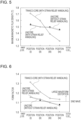
- Fig. 6 shows the evaluation results of the form factor of (dB/dt) obtained by differentiating each magnetic flux waveform with respect to time. Comparing the tranco-core and the unicore, it was found that the unicore has lower magnetic flux concentration and a lower form factor, that is, has suppressed magnetic flux waveform distortion.
- the form factor of time-differentiated (dB/dt) increases. It is assumed that the inner winding portion of the unicore has lower magnetic flux concentration and less magnetic flux waveform distortion than the tranco-core without a bent portion of low magnetic permeability.
- a grain-oriented electrical steel sheet with a magnetic flux density B8 in the range of 1.92 T to 1.98 T at a magnetic field strength H of 800 Aim should be used as an iron core material.
- a single-phase unicore with the shape illustrated in Fig. 3 was produced from a grain-oriented electrical steel sheet with a thickness of 0.23 mm and with a different magnetic flux density B8 shown in Table 1.
- a winding wire was wound 50 turns, and no-load excitation was performed at a magnetic flux density of 1.5 T and at a frequency of 60 Hz.
- a single-turn search coil was placed at the position illustrated in Fig. 4 to examine the magnetic flux density waveform in the iron core and evaluate the form factor of (dB/dt) obtained by differentiating each magnetic flux waveform with respect to time.
- FIG. 8 shows the form factor of (dB/dt) obtained by time-differentiating the magnetic flux waveform at the innermost turn 1/4-thickness (position (i)) in a unicore made of a material (a grain-oriented electrical steel sheet).
- the form factor tends to decrease as the magnetic flux density B8 of the iron core material increases, but on the contrary the form factor increases again in a region with a magnetic flux density B8 of more than 1.98 T.
- a range of 1.92 T to 1.98 T is suitable to suppress the magnetic flux waveform distortion.
- the magnetic flux concentration in the iron core decreases as the magnetic flux density B8 of the grain-oriented electrical steel sheet as a material increases.
- the magnetic flux is generally less likely to be saturated.
- even magnetic flux concentration in the inner side of the iron core caused by the difference in magnetic path length does not cause saturation up to a high magnetic flux density, and it is therefore thought that the trapezoidal magnetic flux waveform distortion described above is less likely to occur.
- an iron core material has a too high magnetic flux density B8, due to high saturation magnetization, this results in excessive magnetic flux concentration caused by the difference in magnetic path length and results in large magnetic flux waveform distortion.
- Magnetic flux density B8 (T) 1 1.90 2 1.91 3 1.92 4 1.93 5 1.94 6 1.96 7 1.97 8 1.98 9 1.99
- the ratio of the length of the outer circumference to the length of the inner circumference of an iron core should be 1.70 or less.
- the magnetic flux waveform distortion is suppressed when the ratio of the length of the outer circumference to the length of the inner circumference is 1.70 or less.
- the length of the inner circumference was calculated by 2(c + d) + 4f x (V2 - 2).
- the length of the outer circumference was calculated by 2(a + b) + 4e x ( ⁇ 2 - 2).
- the length of the inner circumference and the length of the outer circumference may be calculated from the length of each portion as shown in Table 2, or the length of the inner circumference and the length of the outer circumference may be actually measured.
- Magnetic flux concentration in the inner side of an iron core and a trapezoidal distorted magnetic flux waveform as described above increase the iron loss. This is because, in the trapezoidal distorted magnetic flux waveform, the magnetic flux changes abruptly when reaching a side of the trapezoid, thereby increasing the eddy-current loss.
- a single-phase unicore with the shape illustrated in Fig. 3 was produced from grain-oriented electrical steel sheets A to K with a thickness of 0.23 mm and with different iron loss deterioration rates under harmonic superposition shown in Table 3.
- the materials with different iron loss deterioration rates under harmonic superposition were produced by changing the film tension of an insulating film formed on the surface of the electrical steel sheet.
- the iron loss deterioration rate under harmonic superposition decreased as the film tension increased.
- the unicore thus produced was wound with 50 turns of a winding wire and was subjected to no-load excitation at a magnetic flux density of 1.5 T and at a frequency of 60 Hz to measure the iron loss.
- Fig. 11 shows the relationship between the iron loss deterioration rate of a grain-oriented electrical steel sheet as a material under harmonic superposition and the transformer iron loss.
- the transformer iron loss was reduced in a region with an iron loss deterioration rate of 1.30 or less under harmonic superposition.
- the increase in iron loss can be suppressed even when a magnetic flux is concentrated in the inner side of an iron core and the magnetic flux waveform is distorted in a trapezoidal shape.
- the present invention has been made on the basis of these findings and has the following constitution.
- the present invention can provide a wound core with low transformer iron loss and good magnetic characteristics and a method for producing the wound core.
- the present invention can provide a wound core with low transformer iron loss and good magnetic characteristics without using two or more types of materials with different magnetic characteristics (iron loss).
- the present invention can provide a wound core with low iron loss and good magnetic characteristics with high productivity while reducing the complexity of iron core design, such as the arrangement of materials required when two or more types of materials with different magnetic characteristics are used.
- the lengths of the outer circumference and the inner circumference of an iron core in the condition (B) refer to the length of the outer circumference and the length of the inner circumference of the iron core, respectively, when the iron core is viewed from the side.
- the length of the outer circumference of the iron core is the length of one turn in the winding direction of a grain-oriented electrical steel sheet (material) constituting a wound core along the outside (outer surface) of the outermost grain-oriented electrical steel sheet
- the length of the inner circumference of the iron core is the length of one turn in the winding direction of a grain-oriented electrical steel sheet constituting the wound core along the inside (inner surface) of the innermost grain-oriented electrical steel sheet.
- the upper limit of the ratio of the length of the outer circumference to the length of the inner circumference of an iron core should be 1.70.
- the ratio is preferably 1.60 or less, more preferably 1.55 or less.
- the lower limit of the ratio is not particularly defined in terms of characteristics and is determined by the relationship between the iron core size and the thickness because the iron core thickness decreases as the ratio approaches 1. For example, the lower limit of the ratio is 1.05.
- a grain-oriented electrical steel sheet with a magnetic flux density B8 in the range of 1.92 T to 1.98 T at a magnetic field strength H of 800 Aim should be used as an iron core material.
- the magnetic characteristics are measured by the Epstein test.
- the Epstein test is performed by a known method, such as IEC standard or JIS standard.
- the results of a single sheet tester (SST) may be used instead.
- SST single sheet tester
- a representative characteristic of a grain-oriented electrical steel sheet coil should be used for selection in accordance with the preferred range of the magnetic flux density B8. More specifically, a test sample is taken at the front and rear ends of a steel sheet coil and is subjected to the Epstein test to measure the magnetic flux density B8, and the average value thereof is adopted as a representative characteristic.
- the material may be selected on the basis of a characteristic value (an average value and a guaranteed value) of a steel sheet provided by a steel manufacturer.
- the iron loss under harmonic superposition and the iron loss without harmonic superposition defined in the formula are the iron loss (W/kg) measured with an Epstein tester or a single sheet tester at a frequency of 50 Hz and at a maximum magnetization of 1.7 T, and the iron loss under harmonic superposition is the iron loss measured when the superposition ratio of third harmonic to fundamental harmonic at an excitation voltage is 40% and when the phase difference is 60 degrees.
- the harmonic superposition is superimposed on the applied voltage of a primary winding wire.
- a method of harmonic superposition on the applied voltage of the primary winding wire is, for example, but not limited to, a method of generating a harmonic superimposed voltage waveform with a waveform generator and amplifying the waveform with a power amplifier to produce an excitation voltage (a voltage applied to the primary winding wire).
- the harmonic superposition conditions in the present invention include a superposition ratio of third harmonic to fundamental harmonic at an excitation voltage of 40% and a phase difference of 60 degrees.
- a voltage waveform under the harmonic superposition conditions in the present invention is a waveform in which a third harmonic of a 150-Hz sine wave is superimposed on a fundamental harmonic of a 50-Hz sine wave at an amplitude of 40% of the amplitude of the fundamental harmonic with a phase difference delayed by 60 degrees.
- a grain-oriented electrical steel sheet with an iron loss deterioration rate of 1.30 or less under harmonic superposition is used as an iron core material.
- the iron loss deterioration rate under harmonic superposition is preferably 1.28 or less, more preferably 1.25 or less.
- the lower limit of the iron loss deterioration rate under harmonic superposition is, for example, but not limited to, 1.01.
- a chemical composition of a slab for a grain-oriented electrical steel sheet may be a chemical composition that causes secondary recrystallization.
- an inhibitor for example, when an AlN inhibitor is used, appropriate amounts of Al and N may be contained, and when a MnS ⁇ MnSe inhibitor is used, appropriate amounts of Mn and Se and/or S may be contained.
- both inhibitors may be used in combination.
- the preferred Al, N, S, and Se contents are Al: 0.010% to 0.065% by mass, N: 0.0050% to 0.0120% by mass, S: 0.005% to 0.030% by mass, and Se: 0.005% to 0.030% by mass.
- the present invention can also be applied to an inhibitor-free grain-oriented electrical steel sheet with limited Al, N, S, and Se contents.
- the amounts of Al, N, S, and Se are preferably reduced to Al: 100 ppm by mass or less, N: 50 ppm by mass or less, S: 50 ppm by mass or less, and Se: 50 ppm by mass or less.
- C is added to improve the microstructure of a hot-rolled steel sheet.
- a C content of more than 0.08% by mass makes it difficult to reduce the C content to 50 ppm by mass or less at which magnetic aging does not occur in the production process, so that the C content is preferably 0.08% by mass or less.
- the C content has no particular lower limit because secondary recrystallization is possible even in a material containing no C.
- the C content may be 0% by mass.
- Si is an element effective in increasing the electrical resistance of steel and improving iron loss. At a Si content of 2.0% by mass or more, a sufficient iron loss reducing effect is more easily obtained. On the other hand, at a Si content of 8.0% by mass or less, a significant decrease in workability can be suppressed, and a decrease in magnetic flux density can also be easily suppressed. Thus, the Si content preferably ranges from 2.0% to 8.0% by mass.
- Mn is an element necessary for improving hot workability. At a Mn content of 0.005% by mass or more, the effect of addition thereof is easily obtained. On the other hand, at a Mn content of 1.000% by mass or less, the decrease in the magnetic flux density of a product sheet is easily suppressed. Thus, the Mn content preferably ranges from 0.005% to 1.000% by mass.
- Cr is an element that promotes the formation of a dense oxide film at the interface between a forsterite film and a steel substrate.
- an oxide film can be formed without the addition of Cr, the addition of 0.02% by mass or more of Cr is expected to expand a preferred range of other components.
- the Cr content preferably ranges from 0.02% to 0.20% by mass.
- the slab for a grain-oriented electrical steel sheet preferably contains these components as base components.
- the slab may appropriately contain the following elements.
- Ni 0.03% to 1.50% by mass
- Sn 0.010% to 1.500% by mass
- Sb 0.005% to 1.500% by mass
- Cu 0.02% to 0.20% by mass
- P 0.03% to 0.50% by mass
- Mo 0.005% to 0.100% by mass
- Ni is an element useful for improving the microstructure of a hot-rolled steel sheet and improving magnetic characteristics. At a Ni content of 0.03% by mass or more, the effect of improving the magnetic characteristics is more easily obtained. At a Ni content of 1.50% by mass or less, it is possible to suppress secondary recrystallization from becoming unstable, and it is easy to reduce the possibility that the magnetic characteristics of a product sheet deteriorate. Thus, when Ni is contained, the Ni content preferably ranges from 0.03% to 1.50% by mass.
- Sn, Sb, Cu, P, and Mo are elements useful for improving the magnetic characteristics, and at a content thereof above their respective lower limits, the effect of improving the magnetic characteristics is more easily obtained. On the other hand, at a content thereof below their respective upper limits, it is easy to reduce the possibility that the development of secondary recrystallized grains is inhibited.
- each element content is preferably within the above range.
- the remainder other than these components is composed of incidental impurities in the production process and Fe.
- a slab with the chemical composition described above is heated in the usual manner.
- the heating temperature preferably ranges from 1150°C to 1450°C.
- the heating is followed by hot rolling. After casting, hot rolling may be performed immediately without heating.
- a thin cast steel may be or may not be hot-rolled.
- the rolling temperature in the final rough rolling pass is 900°C or more, and the rolling temperature in the final finish rolling pass is 700°C or more.
- the annealing temperature of the hot-rolled steel sheet preferably ranges from 800°C to 1100°C.
- the band microstructure in the hot rolling remains, and it is difficult to realize a primary recrystallization texture with a controlled grain size, and the development of secondary recrystallization may be inhibited.
- the grain size after annealing of the hot-rolled steel sheet becomes too coarse, so that it may be extremely difficult to realize a primary recrystallization texture with a controlled grain size.
- the intermediate annealing temperature preferably ranges from 800°C to 1150°C.
- the intermediate annealing time preferably ranges from approximately 10 to 100 seconds.
- the annealing temperature ranges from 750°C to 900°C
- the oxidizing atmosphere PH 2 O/PH 2 ranges from 0.25 to 0.60
- the annealing time ranges from approximately 50 to 300 seconds.
- the annealing separator is preferably composed mainly of MgO and is preferably applied in an amount in the range of approximately 8 to 15 g/m 2 .
- finish annealing is performed for the purpose of secondary recrystallization and the formation of a forsterite film.
- the annealing temperature is preferably 1100°C or more, and the annealing time is preferably 30 minutes or more.
- flattening treatment flattening annealing
- insulating coating can be applied to the surface of a steel sheet before or after the flattening annealing.
- the term "insulating coating”, as used herein, refers to coating (tension coating) that applies tension to a steel sheet to reduce iron loss.
- the tension coating may be inorganic coating containing silica, ceramic coating by a physical vapor deposition method or a chemical vapor deposition method, or the like.
- the iron loss deterioration rate under harmonic superposition decreases as the tensile strength of a surface film (a forsterite film and insulating coating) applied to a steel sheet increases.
- the thickness of tension coating may be increased to increase film tension, the lamination factor may deteriorate.
- the baking temperature may be increased to promote glass crystallization.
- the application of a film with a low thermal expansion coefficient, such as ceramic coating, is also effective in obtaining high tension.
- the magnetic domain refining technique is a technique of introducing nonuniformity into the surface of a steel sheet by a physical method and refining the width of a magnetic domain to reduce the iron loss.
- the magnetic domain refining technique is broadly divided into heat-resistant magnetic domain refining in which the effect is not lost in strain relief annealing and non-heat-resistant magnetic domain refining in which the effect is reduced by strain relief annealing.
- the present invention can be applied to any of a steel sheet not subjected to magnetic domain refining treatment, a steel sheet subjected to heat-resistant magnetic domain refining treatment, and a steel sheet subjected to non-heat-resistant magnetic domain refining treatment.
- a steel sheet subjected to non-heat-resistant magnetic domain refining treatment is more preferred than a steel sheet subjected to heat-resistant magnetic domain refining treatment.
- the non-heat-resistant magnetic domain refining treatment is typically a treatment of irradiating a steel sheet after secondary recrystallization with a high-energy beam (a laser or the like) to introduce a high dislocation density region into a steel sheet surface layer and form a stress field associated therewith, thereby performing magnetic domain refining.
- a non-heat-resistant magnetic domain refined material a steel sheet subjected to non-heat-resistant magnetic domain refining treatment
- a strong tensile field is formed on the outermost surface of the steel sheet due to the introduction of a high dislocation density region, so that an increase in eddy-current loss due to harmonic superposition can be avoided.
- a strain-induced non-heat-resistant magnetic domain refining treatment method a known technique, such as irradiating the surface of a steel sheet with a high-energy beam (a laser, an electron beam, a plasma jet, or the like), can be applied.
- the present invention is more specifically described in the following examples.
- the examples are preferred examples of the present invention, and the present invention is not limited to these examples.
- the embodiments of the present invention can be appropriately modified within the scope of the gist of the present invention, and all of them are included in the technical scope of the present invention.
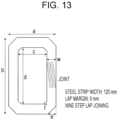
- a single-phase tranco-core and a single-phase unicore with an iron core shape shown in Fig. 12 and Table 4 and in Fig. 13 and Table 5 were produced from a grain-oriented electrical steel sheet, which is an iron core material, shown in Table 6.
- strain relief annealing was performed at 800°C for 2 hours to remove strain, and after annealing, the iron core was unwound from the joint, and a 50-turn winding coil was inserted.
- the winding coil was inserted without strain relief annealing.
- the transformer iron loss was measured at an excitation magnetic flux density (Bm) of 1.5 T and at a frequency (f) of 60 Hz.
- an Epstein test result of an iron core material (in the case of non-heat-resistant magnetic domain refining, a single-sheet magnetic measurement result) was taken as material iron loss, and the iron loss increase rate BF in transformer iron loss with respect to the material iron loss was determined.
- Table 4 transcription-core
- the length of the inner circumference was calculated by 2(c + d) - 8f x (1 - ⁇ x 90 (degrees) /360 (degrees)).
- the length of the outer circumference was calculated by 2(a + b) - 8e x (1 - ⁇ x 90 (degrees)/360 (degrees)).
- Table 6 shows the results. It was found that the examples and optimal examples of the present invention have better BF and much better transformer characteristics than comparative examples. In particular, the optimal examples using a non-heat-resistant magnetic domain refined material had particularly low transformer iron loss.
- Condition Wound core Iron core material (grain-oriented electrical steel sheet) Excitation conditions Bm: 1.5T, f: 60Hz Notes Strain relief annealing Iron core shape Ratio of length of outer circumference to length of inner circumference of iron core Magnetic flux density B8 (T) Iron loss deterioration rate under harmonic superposition Magnetic domain refining Material iron loss (W/kg) Transformer iron loss (W/kg) BF 1 Tranco-core A 1.48 1.96 1.21 No 0.76 1.00 1.31 Comparative example 2 Tranco-core A 1.48 1.92 1.13 Heat-resistant magnetic domain refining 0.67 0.86 1.29 Comparative example 3 Tranco-core B 1.68 1.94 1.22 No 0.78 1.04 1.33 Comparative example 4 Tranco-core B 1.68 1.90 1.14 Heat
Landscapes
- Engineering & Computer Science (AREA)
- Power Engineering (AREA)
- Chemical & Material Sciences (AREA)
- Manufacturing & Machinery (AREA)
- Physics & Mathematics (AREA)
- Metallurgy (AREA)
- Mechanical Engineering (AREA)
- Materials Engineering (AREA)
- Organic Chemistry (AREA)
- Crystallography & Structural Chemistry (AREA)
- Thermal Sciences (AREA)
- Electromagnetism (AREA)
- Soft Magnetic Materials (AREA)
Applications Claiming Priority (2)
| Application Number | Priority Date | Filing Date | Title |
|---|---|---|---|
| JP2021124864 | 2021-07-30 | ||
| PCT/JP2022/023039 WO2023007953A1 (ja) | 2021-07-30 | 2022-06-08 | 巻鉄心および巻鉄心の製造方法 |
Publications (1)
| Publication Number | Publication Date |
|---|---|
| EP4343796A1 true EP4343796A1 (de) | 2024-03-27 |
Family
ID=83593720
Family Applications (1)
| Application Number | Title | Priority Date | Filing Date |
|---|---|---|---|
| EP22849032.2A Pending EP4343796A1 (de) | 2021-07-30 | 2022-06-08 | Gewickelter kern und verfahren zur herstellung eines gewickelten kerns |
Country Status (5)
| Country | Link |
|---|---|
| EP (1) | EP4343796A1 (de) |
| JP (1) | JP7151947B1 (de) |
| KR (1) | KR20240021277A (de) |
| CN (1) | CN117652005A (de) |
| CA (1) | CA3219694A1 (de) |
Family Cites Families (7)
| Publication number | Priority date | Publication date | Assignee | Title |
|---|---|---|---|---|
| JP2895670B2 (ja) | 1991-10-24 | 1999-05-24 | 川崎製鉄株式会社 | 鉄損の低い方向性電磁鋼板及びその製造方法 |
| JP2006185999A (ja) | 2004-12-27 | 2006-07-13 | Nippon Steel Corp | ビルディングファクタの低い変圧器およびリアクトル鉄心の製造方法 |
| CN1897175B (zh) | 2005-07-08 | 2012-07-18 | 株式会社日立产机系统 | 静止装置用铁芯和静止装置 |
| JP5434644B2 (ja) * | 2010-02-08 | 2014-03-05 | Jfeスチール株式会社 | 方向性電磁鋼板の製造方法 |
| JP5938866B2 (ja) * | 2010-10-14 | 2016-06-22 | Jfeスチール株式会社 | 方向性電磁鋼板およびその製造方法 |
| WO2019009311A1 (ja) * | 2017-07-04 | 2019-01-10 | 日立金属株式会社 | 巻磁心及び巻磁心の製造方法 |
| JP7167779B2 (ja) * | 2019-03-12 | 2022-11-09 | 日本製鉄株式会社 | 鉄芯、巻鉄芯の製造方法、積鉄芯の製造方法及び鉄芯用電磁鋼板の製造方法 |
-
2022
- 2022-06-08 EP EP22849032.2A patent/EP4343796A1/de active Pending
- 2022-06-08 KR KR1020247001270A patent/KR20240021277A/ko unknown
- 2022-06-08 CA CA3219694A patent/CA3219694A1/en active Pending
- 2022-06-08 JP JP2022544248A patent/JP7151947B1/ja active Active
- 2022-06-08 CN CN202280050560.0A patent/CN117652005A/zh active Pending
Also Published As
| Publication number | Publication date |
|---|---|
| CA3219694A1 (en) | 2023-02-02 |
| CN117652005A (zh) | 2024-03-05 |
| KR20240021277A (ko) | 2024-02-16 |
| JP7151947B1 (ja) | 2022-10-12 |
| JPWO2023007953A1 (de) | 2023-02-02 |
Similar Documents
| Publication | Publication Date | Title |
|---|---|---|
| JP5115641B2 (ja) | 方向性電磁鋼板およびその製造方法 | |
| KR101421387B1 (ko) | 방향성 전기 강판 및 그 제조 방법 | |
| EP2602345A1 (de) | Kornorientiertes magnetisches stahlblech und herstellungsverfahren dafür | |
| KR101530450B1 (ko) | 방향성 전기 강판 | |
| KR101607909B1 (ko) | 방향성 전자 강판 및 그것을 이용한 변압기 철심 | |
| WO2015111434A1 (ja) | 方向性電磁鋼板およびその製造方法 | |
| EP2963130A1 (de) | Herstellungsverfahren für kornorientierte elektrostahlbleche | |
| JP4120121B2 (ja) | 方向性電磁鋼板の製造方法 | |
| JP5983306B2 (ja) | 鉄損に優れた変圧器鉄心の製造方法 | |
| EP3734623A1 (de) | Kornorientiertes elektrostahlblech, gestapelter transformatorkern mit verwendung davon und verfahren zur herstellung des gestapelten kerns | |
| EP4343796A1 (de) | Gewickelter kern und verfahren zur herstellung eines gewickelten kerns | |
| JP5565307B2 (ja) | 方向性電磁鋼板の製造方法 | |
| JP6003321B2 (ja) | 方向性電磁鋼板の製造方法 | |
| JP2020105589A (ja) | 方向性電磁鋼板およびその製造方法 | |
| EP4343009A1 (de) | Gewickelter kern und verfahren zur herstellung eines gewickelten kerns | |
| WO2023167016A1 (ja) | 三相三脚巻鉄心およびその製造方法 | |
| JP7318846B1 (ja) | 三相三脚巻鉄心およびその製造方法 | |
| WO2023007953A1 (ja) | 巻鉄心および巻鉄心の製造方法 | |
| CN116348620A (zh) | 卷绕铁芯 | |
| WO2023007952A1 (ja) | 巻鉄心および巻鉄心の製造方法 | |
| JP7318845B1 (ja) | 三相三脚巻鉄心およびその製造方法 | |
| WO2023167015A1 (ja) | 三相三脚巻鉄心およびその製造方法 | |
| JP5845848B2 (ja) | 方向性電磁鋼板の製造方法 | |
| JP2013234342A (ja) | 磁区細分化処理方法および方向性電磁鋼板 | |
| WO2022255014A1 (ja) | 方向性電磁鋼板 |
Legal Events
| Date | Code | Title | Description |
|---|---|---|---|
| STAA | Information on the status of an ep patent application or granted ep patent |
Free format text: STATUS: THE INTERNATIONAL PUBLICATION HAS BEEN MADE |
|
| PUAI | Public reference made under article 153(3) epc to a published international application that has entered the european phase |
Free format text: ORIGINAL CODE: 0009012 |
|
| STAA | Information on the status of an ep patent application or granted ep patent |
Free format text: STATUS: REQUEST FOR EXAMINATION WAS MADE |
|
| 17P | Request for examination filed |
Effective date: 20231218 |
|
| AK | Designated contracting states |
Kind code of ref document: A1 Designated state(s): AL AT BE BG CH CY CZ DE DK EE ES FI FR GB GR HR HU IE IS IT LI LT LU LV MC MK MT NL NO PL PT RO RS SE SI SK SM TR |