EP4343183A1 - Système d'étanchéité pour soupapes d'écoulement de fluide commutables - Google Patents
Système d'étanchéité pour soupapes d'écoulement de fluide commutables Download PDFInfo
- Publication number
- EP4343183A1 EP4343183A1 EP22196734.2A EP22196734A EP4343183A1 EP 4343183 A1 EP4343183 A1 EP 4343183A1 EP 22196734 A EP22196734 A EP 22196734A EP 4343183 A1 EP4343183 A1 EP 4343183A1
- Authority
- EP
- European Patent Office
- Prior art keywords
- sealing
- valve
- force limiting
- water valves
- sealing system
- Prior art date
- Legal status (The legal status is an assumption and is not a legal conclusion. Google has not performed a legal analysis and makes no representation as to the accuracy of the status listed.)
- Pending
Links
- 238000007789 sealing Methods 0.000 title claims abstract description 132
- 239000012530 fluid Substances 0.000 title abstract description 5
- XLYOFNOQVPJJNP-UHFFFAOYSA-N water Substances O XLYOFNOQVPJJNP-UHFFFAOYSA-N 0.000 claims abstract description 48
- 230000000694 effects Effects 0.000 claims abstract description 9
- 238000013016 damping Methods 0.000 claims abstract description 7
- 230000008878 coupling Effects 0.000 claims description 9
- 238000010168 coupling process Methods 0.000 claims description 9
- 238000005859 coupling reaction Methods 0.000 claims description 9
- 238000007667 floating Methods 0.000 claims description 6
- 239000000463 material Substances 0.000 claims description 5
- 230000005540 biological transmission Effects 0.000 claims description 3
- 238000010438 heat treatment Methods 0.000 abstract description 2
- 230000036316 preload Effects 0.000 description 11
- 239000000243 solution Substances 0.000 description 6
- 230000015572 biosynthetic process Effects 0.000 description 4
- 238000005755 formation reaction Methods 0.000 description 4
- 229920001971 elastomer Polymers 0.000 description 2
- 239000000806 elastomer Substances 0.000 description 2
- 238000009434 installation Methods 0.000 description 2
- 238000004519 manufacturing process Methods 0.000 description 2
- 238000000034 method Methods 0.000 description 2
- 210000000078 claw Anatomy 0.000 description 1
- 238000002485 combustion reaction Methods 0.000 description 1
- 238000010276 construction Methods 0.000 description 1
- 238000011109 contamination Methods 0.000 description 1
- 230000001419 dependent effect Effects 0.000 description 1
- 239000013536 elastomeric material Substances 0.000 description 1
- 239000007770 graphite material Substances 0.000 description 1
- 230000009191 jumping Effects 0.000 description 1
- 239000002184 metal Substances 0.000 description 1
- 238000000465 moulding Methods 0.000 description 1
- 229910001220 stainless steel Inorganic materials 0.000 description 1
- 239000010935 stainless steel Substances 0.000 description 1
Images


Classifications
-
- F—MECHANICAL ENGINEERING; LIGHTING; HEATING; WEAPONS; BLASTING
- F16—ENGINEERING ELEMENTS AND UNITS; GENERAL MEASURES FOR PRODUCING AND MAINTAINING EFFECTIVE FUNCTIONING OF MACHINES OR INSTALLATIONS; THERMAL INSULATION IN GENERAL
- F16K—VALVES; TAPS; COCKS; ACTUATING-FLOATS; DEVICES FOR VENTING OR AERATING
- F16K11/00—Multiple-way valves, e.g. mixing valves; Pipe fittings incorporating such valves
- F16K11/02—Multiple-way valves, e.g. mixing valves; Pipe fittings incorporating such valves with all movable sealing faces moving as one unit
- F16K11/04—Multiple-way valves, e.g. mixing valves; Pipe fittings incorporating such valves with all movable sealing faces moving as one unit comprising only lift valves
- F16K11/044—Multiple-way valves, e.g. mixing valves; Pipe fittings incorporating such valves with all movable sealing faces moving as one unit comprising only lift valves with movable valve members positioned between valve seats
-
- F—MECHANICAL ENGINEERING; LIGHTING; HEATING; WEAPONS; BLASTING
- F16—ENGINEERING ELEMENTS AND UNITS; GENERAL MEASURES FOR PRODUCING AND MAINTAINING EFFECTIVE FUNCTIONING OF MACHINES OR INSTALLATIONS; THERMAL INSULATION IN GENERAL
- F16K—VALVES; TAPS; COCKS; ACTUATING-FLOATS; DEVICES FOR VENTING OR AERATING
- F16K1/00—Lift valves or globe valves, i.e. cut-off apparatus with closure members having at least a component of their opening and closing motion perpendicular to the closing faces
- F16K1/32—Details
- F16K1/48—Attaching valve members to screw-spindles
-
- F—MECHANICAL ENGINEERING; LIGHTING; HEATING; WEAPONS; BLASTING
- F16—ENGINEERING ELEMENTS AND UNITS; GENERAL MEASURES FOR PRODUCING AND MAINTAINING EFFECTIVE FUNCTIONING OF MACHINES OR INSTALLATIONS; THERMAL INSULATION IN GENERAL
- F16K—VALVES; TAPS; COCKS; ACTUATING-FLOATS; DEVICES FOR VENTING OR AERATING
- F16K27/00—Construction of housing; Use of materials therefor
- F16K27/02—Construction of housing; Use of materials therefor of lift valves
- F16K27/0263—Construction of housing; Use of materials therefor of lift valves multiple way valves
-
- F—MECHANICAL ENGINEERING; LIGHTING; HEATING; WEAPONS; BLASTING
- F16—ENGINEERING ELEMENTS AND UNITS; GENERAL MEASURES FOR PRODUCING AND MAINTAINING EFFECTIVE FUNCTIONING OF MACHINES OR INSTALLATIONS; THERMAL INSULATION IN GENERAL
- F16K—VALVES; TAPS; COCKS; ACTUATING-FLOATS; DEVICES FOR VENTING OR AERATING
- F16K27/00—Construction of housing; Use of materials therefor
- F16K27/02—Construction of housing; Use of materials therefor of lift valves
- F16K27/029—Electromagnetically actuated valves
-
- F—MECHANICAL ENGINEERING; LIGHTING; HEATING; WEAPONS; BLASTING
- F16—ENGINEERING ELEMENTS AND UNITS; GENERAL MEASURES FOR PRODUCING AND MAINTAINING EFFECTIVE FUNCTIONING OF MACHINES OR INSTALLATIONS; THERMAL INSULATION IN GENERAL
- F16K—VALVES; TAPS; COCKS; ACTUATING-FLOATS; DEVICES FOR VENTING OR AERATING
- F16K31/00—Actuating devices; Operating means; Releasing devices
- F16K31/02—Actuating devices; Operating means; Releasing devices electric; magnetic
- F16K31/04—Actuating devices; Operating means; Releasing devices electric; magnetic using a motor
- F16K31/047—Actuating devices; Operating means; Releasing devices electric; magnetic using a motor characterised by mechanical means between the motor and the valve, e.g. lost motion means reducing backlash, clutches, brakes or return means
-
- F—MECHANICAL ENGINEERING; LIGHTING; HEATING; WEAPONS; BLASTING
- F16—ENGINEERING ELEMENTS AND UNITS; GENERAL MEASURES FOR PRODUCING AND MAINTAINING EFFECTIVE FUNCTIONING OF MACHINES OR INSTALLATIONS; THERMAL INSULATION IN GENERAL
- F16K—VALVES; TAPS; COCKS; ACTUATING-FLOATS; DEVICES FOR VENTING OR AERATING
- F16K47/00—Means in valves for absorbing fluid energy
- F16K47/01—Damping of valve members
-
- F—MECHANICAL ENGINEERING; LIGHTING; HEATING; WEAPONS; BLASTING
- F16—ENGINEERING ELEMENTS AND UNITS; GENERAL MEASURES FOR PRODUCING AND MAINTAINING EFFECTIVE FUNCTIONING OF MACHINES OR INSTALLATIONS; THERMAL INSULATION IN GENERAL
- F16K—VALVES; TAPS; COCKS; ACTUATING-FLOATS; DEVICES FOR VENTING OR AERATING
- F16K2200/00—Details of valves
- F16K2200/10—Means for compensation of misalignment between seat and closure member
- F16K2200/101—Means for compensation of misalignment between seat and closure member closure member self-aligning to seat
-
- F—MECHANICAL ENGINEERING; LIGHTING; HEATING; WEAPONS; BLASTING
- F24—HEATING; RANGES; VENTILATING
- F24D—DOMESTIC- OR SPACE-HEATING SYSTEMS, e.g. CENTRAL HEATING SYSTEMS; DOMESTIC HOT-WATER SUPPLY SYSTEMS; ELEMENTS OR COMPONENTS THEREFOR
- F24D19/00—Details
- F24D19/10—Arrangement or mounting of control or safety devices
- F24D19/1006—Arrangement or mounting of control or safety devices for water heating systems
- F24D19/1009—Arrangement or mounting of control or safety devices for water heating systems for central heating
- F24D19/1015—Arrangement or mounting of control or safety devices for water heating systems for central heating using a valve or valves
- F24D19/1024—Arrangement or mounting of control or safety devices for water heating systems for central heating using a valve or valves a multiple way valve
- F24D19/1033—Arrangement or mounting of control or safety devices for water heating systems for central heating using a valve or valves a multiple way valve motor operated
Definitions
- the invention relates to a sealing system for switchable fluid-flowing water valves for use in heaters and water boilers, in particular for three-way water valves.
- valves through which fluid flows are known, which interrupt the water flow for water circuits or reverse it if necessary.
- the valves are completely open or completely closed and are actuated by stepper motors that generate linear movement.
- Electromechanically operated two-way valves or three-way valves are therefore preferably used. These valves must be designed in such a way that there is no significant pressure drop in them during the water flow and that leaks within the water circuits can be reliably excluded in the valve area over the entire temperature range in which they are operated.
- Stepper motors with linear movement work on the principle of a claw pole motor. If the motor moves to an end stop, a force corresponding to the spring rate of the system is built up based on the elastic properties of the stop and the linear stepper motor. As soon as the linear stepper motor reaches its force limit, which is linked to the magnetic properties of the system, the rotor jumps back and forth in an uncontrolled manner in non-definable step patterns. These step patterns usually cause the rotor to move in an opposing direction. This in turn leads to a loss of force in the end stop system due to its spring rate, which is greater the greater the spring rate of the system.
- the disadvantage is the hard and direct coupling between the engine and the coupled valve system, whereby the seal used determines the majority of the rigidity of the entire system and is therefore very difficult to optimally adjust.
- the sealing body described here is a type of sealing ball made of a cylindrical metal body, which in turn has to be moved into cylindrical sealing surfaces.
- a side ring (which acts as an actual sealing ring) is arranged in the valve body, which must be compressed radially so that it can ensure sealing.
- This design is also intended to prevent any contamination or deposits inside the valve body or to have no influence on the tightness of the valve.
- a valve which serves as an exhaust gas recirculation valve for internal combustion engines.
- an electric motor-operated rotating screw drive is designed, which moves a spindle nut.
- a return spring comes into effect, which moves the rotary magnet back to its starting position.
- a second return spring is also attached.
- the return springs described here are arranged inside, i.e. directly in the motor housing. An oscillating movement is not compensated for.
- the US 4,751,411 A describes a linear stepper motor with a threaded shaft where axial movement is carried out for a valve body.
- a helical spring is arranged at one end of the threaded shaft and is prestressed by the axial movement of the threaded shaft. This is intended to prevent a defined play of the screw element between the shaft and the rotor of the linear stepper motor, so that the drive can be operated with a high level of accuracy.
- a flow control device for a gas valve which is operated with a linearly actuable stepper motor, is described.
- a preload is created on the valve shaft by means of a coil spring.
- Such return springs, or coil springs, which generate a defined preload or are used to release from a specific stop position, are also in the WO2021156836 A1 , the WO 2017060927 A2 , the US 4501981 A , the JP 2016059170 A , the CN 103872840 B , the CN 206452198 U , the CN 204334281 U , the CN213185851 U and the EP2748487 B1 described.
- the object of the invention is to create a sealing system for switchable fluid-flowing water valves for use preferably in heaters and water boilers, which is structurally simple, consists of very few individual parts with the least amount of material used, can be assembled quickly and automatically, has a low flow resistance in the open state, has no leakage in both valve positions, has a long service life and reliably prevents a sealing body from springing back or oscillating in the respective stop.
- a sealing body 8 When it abuts against a sealing edge or sealing surface 21 in a sealing system for switchable fluid-flowing water valves 1, consisting of a valve body 5, a cartridge 2 flanged thereto and a drive arranged thereon by means of a linear motor and one in a valve body 5 between sealing surfaces / sealing edges 21 arranged valve base body 7, with one or more sealing body (s) 8 arranged thereon and adjustment via a valve adjusting rod 4 to reliably prevent, according to the invention within the force transmission path at least one force limiting element 9 with a defined damping effect or a defined preload exerting effect arranged.
- a sealing surface/sealing edge 21 of the valve body 5 encloses a sealing body 8 in the closed state.
- sealing bodies 8, which are applied to a sealing base body 7, are arranged to be suitably floating or floatingly suspended over this sealing base body 7, in that the valve adjusting rod 4 is mounted and guided in a valve adjusting rod bushing 18, which is designed with a specially designed inner cross-sectional shape serves as implementation.
- This cross-sectional shape is spherical
- the force limiting element 9 in such a sealing system for switchable fluid-flowing water valves 1 is designed in such a way that it acts on both sides and/or is also arranged in such a way that it is advantageously biased into engagement. In principle, it can also be installed without preload, but the adjustment ranges are then considerably longer.
- the preload can be adjusted once during assembly in a range up to the maximum required sealing force.
- the force limiting element 9 consists of four spring elements 9 distributed around the circumference in this sealing system for switchable fluid-flowing water valves 1. These are arranged between the cartridge 2 and the linear motor. Four spring-coated sliding pins offset by 90 degrees are arranged and guided in four sliding bushings in the cartridge, with the spring elements 9 being installed under a defined preload. As a result, the valve base body 7 can be prevented from springing back. It makes sense if the coupling element 6 between the linear motor and the valve adjusting rod 4 is designed as a gimbal.
- the linear motor is therefore axially spring-loaded within certain limits relative to the cartridge 2 and is fastened in a displaceable manner and can therefore carry out a small axially oscillating movement without this being via the coupling point and the valve adjusting rod 4 and the valve base body 7 connected to it and the sealing body(s) arranged thereon 8 can be transferred.
- noise entering the water pipe is largely avoided.
- the valve adjusting rod 4 is mounted floating in the valve base body 7, as already described above.
- the sealing system for switchable fluid-flow water valves 1 it is also possible in the sealing system for switchable fluid-flow water valves 1 to arrange the force limiting element 9 between the linear motor and the valve actuating rod 4 in or on a coupling element 6.
- the spring elements 9 within the coupling element 6 are, for example, a pre-stressed, arched leaf spring or two small coil springs arranged in such a way that they act against the end of the valve actuating rod 4 that protrudes into the coupling element 6 or is connected to it and thus a defined pre-stress acts on the sealing element(s) 8 via the valve actuating rod 4, which is mounted and guided in a floating manner in the valve base body 7.
- the oscillating movement is absorbed by this force limiting element 9, so that a uniform sealing body contact pressure is guaranteed in the two possible closed positions of the valve base body 7.
- the force limiting element 9 can be arranged between the cartridge 2 and the valve body 5. It is advantageous here if an annular double resilient elastomer ring is arranged as a force limiting element 9 at the connection point between the two.
- the elastomer ring is dimensioned so that it can exert sufficient preload on the valve adjusting rod 4 and prevents oscillating movement of the sealing body(s) 8.
- the force limiting element 9 can also be designed to be integrated into the valve adjusting rod 4.
- the valve adjusting rod is designed in the form of a double-resilient telescopic rod.
- the force limiting element 9 can be arranged directly at the connection point between the valve adjusting rod 4 and the valve base body 7.
- the spring element 9 can be designed as one large or two very soft sealing bodies 8, whereby the adjusting rod can then be moved in a defined manner or relatively slowly, so that the force only increases slowly. This may require a long travel distance and a large installation space.
- the force limiting element 9 is/are designed as one or more separate components.
- the force limiting element 9 can be constructed from one or more coil springs 14, as leaf springs, or as a part made of a suitable elastomeric material or a plastic material with correspondingly resilient properties and each installed under a defined preload.
- the advantage of the sealing system according to the invention for switchable fluid-flowing water valves for use in heaters and water boilers is that the spring rate of any linear motor system in operation can be reduced to a significantly lower level, so that the force losses associated with the step losses are negligibly small and a consistently good seal is guaranteed in the closed position.
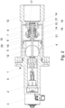
- FIG. 1 For the sake of clarity, a sectional view of a three-way water valve 10 is shown with the possible arrangement variants of one or more force limiting elements 9 according to the invention according to claims 3 to 8.
- FIG. 2 is shown as a sectional view of a stylized water valve 1 with the arrangement of the force limiting element 9 inside the valve base body 7.
- a cylindrical cavity is formed in the valve base body 7. This cavity can optionally be designed to be sealed by arranging a simple zero ring under a closure element.
- the valve adjusting rod 4 is guided into this cavity.
- a double shaft flange 15 is firmly connected to this in the area of the cylindrical cavity.
- valve rod bushing 18 in which the valve rod 4 is slidably mounted, is spherical on the inside when viewed in cross section, that is, the diameter of the passage for the valve adjusting rod 4 tapers towards the middle of this component and then expands again.
- the valve adjusting rod 4 can assume a different, slightly oblique position relative to the axis of symmetry. This means that e.g. B. a flow-related slight deflection from the optimal, exactly central position of the sealing body 8 or the sealing base body 7 cannot cause any tightness problems.
- the sealing body 8 also seals optimally in a position that is not exactly central relative to the sealing surface/sealing edge 21.
- the two coil springs 14 are dimensioned such that they are compressed during installation by means of the lockable valve rod bushing 18, so that they have a defined preload when installed.
- the valve rod bushing 18 is fixed in its position in the valve base body 7 by means of a suitable anti-rotation device or by a bayonet lock on the valve rod bushing collar 19 arranged elevations.
- the guide ring 17 acts as an end stop when the valve adjusting rod 4 is moved in the direction of the axial drain opening 12.
- the inner surface of the valve rod bushing 18 (not designated) acts as a left-hand end stop when the valve adjusting rod 4 is moved in the direction of the radially arranged drain opening 12.
- valve base body 7 is moved to the left by the linear stepper motor 3 until the left sealing body 8 runs against the left sealing surface/sealing edge 21. Then the left coil spring 9 is pressed against the inner surface of the valve rod bushing collar 19 due to the shaft double flange 15 fixedly arranged on the valve adjusting rod 4 and the other damping ring 16, so that a sufficiently high contact pressure can also be exerted on the left sealing body 8. The effect is the same as already described above for the right position of the valve base body 7.
- FIG. 3 the arrangement of several force limiting elements 9 between linear stepper motor 3 and cartridge 2 with four radially distributed sliding pins 22, which are guided and fastened in sliding bushings 23 which are guided and fastened to cartridge flanges/cartridge formations 24, is shown.
- the sliding pins 22 are firmly connected to a linear stepper motor flange/linear stepper motor formations 25; here in this exemplary embodiment they are screwed using motor flange screws 13.
- Four helical springs 14 enveloping the sliding bushings 23 are arranged as force limiting elements 9 and are pretensioned in such a way that two each develop their effect in the left closed position and two each in the right closed position.
- the floating mounting of the valve rod 4 inside the valve base body 7 is not shown here.
- the left sealing body 8 rests on the left sealing surface/sealing edge 21 of the valve body 5, so that the water, which flows through the inflow opening 11 into the interior of the valve body 5, can flow out to the right out of the right axial drain opening 12. If the sealing body 8 runs against the left sealing surface/sealing edge 21, the rotor jumps back and forth in an uncontrolled manner in non-definable step patterns. Due to the preload and the movement of the sliding pin 22 to the right, the contact pressure on the left sealing body 8 increases by compressing the upper coil spring 14.
- the valve control rod 4 is connected to the linear stepper motor 3 through a sealing passage above the coupling point 6 inside the cartridge 2. Due to the spring-loaded sliding pins 22, the linear stepper motor 3 can carry out axially oscillating movements when the sealing bodies 8 come into contact with the sealing surfaces/sealing edges 21.
- the lower representation of the sliding pin 22 shows the construction and mode of operation for the left-hand stop of the sealing bodies 8.
- This sliding pin 22 is screwed to the linear stepper motor flange/or a linear stepper motor formation 25.
- the linear stepper motor 3 causes the rotor to jump back and forth in an uncontrolled manner, ie in an undefined step pattern.
- the sliding pins 22 move to the right.
- the upper sliding pin 22 initially slides to the right in the upper sliding bushing 23, runs and takes it with it, thereby compressing the upper spring element 9. Due to the coordinated dimensioning of the springs 9, the sliding pin shoulders 26 and the length of the sliding bush bore in the sliding bush 23, the motor force to be applied is limited in a defined manner.
Landscapes
- Engineering & Computer Science (AREA)
- General Engineering & Computer Science (AREA)
- Mechanical Engineering (AREA)
- Physics & Mathematics (AREA)
- Electromagnetism (AREA)
- Multiple-Way Valves (AREA)
Priority Applications (1)
| Application Number | Priority Date | Filing Date | Title |
|---|---|---|---|
| EP22196734.2A EP4343183A1 (fr) | 2022-09-20 | 2022-09-20 | Système d'étanchéité pour soupapes d'écoulement de fluide commutables |
Applications Claiming Priority (1)
| Application Number | Priority Date | Filing Date | Title |
|---|---|---|---|
| EP22196734.2A EP4343183A1 (fr) | 2022-09-20 | 2022-09-20 | Système d'étanchéité pour soupapes d'écoulement de fluide commutables |
Publications (1)
| Publication Number | Publication Date |
|---|---|
| EP4343183A1 true EP4343183A1 (fr) | 2024-03-27 |
Family
ID=83398172
Family Applications (1)
| Application Number | Title | Priority Date | Filing Date |
|---|---|---|---|
| EP22196734.2A Pending EP4343183A1 (fr) | 2022-09-20 | 2022-09-20 | Système d'étanchéité pour soupapes d'écoulement de fluide commutables |
Country Status (1)
| Country | Link |
|---|---|
| EP (1) | EP4343183A1 (fr) |
Citations (26)
| Publication number | Priority date | Publication date | Assignee | Title |
|---|---|---|---|---|
| CH231313A (de) * | 1939-07-28 | 1944-03-15 | Schaltapparate Ag F | Spindelverstelleinrichtung. |
| US4501981A (en) | 1981-10-15 | 1985-02-26 | Haydon Switch & Instrument, Inc. | Return-to-zero stepper motor |
| US4751411A (en) | 1985-09-30 | 1988-06-14 | Aisan Kogyo Kabushiki Kaisha | Step motor |
| FR2719101A1 (fr) * | 1994-04-25 | 1995-10-27 | Chaffoteaux Et Maury | Perfectionnements aux vannes à trois voies à commande électrique. |
| GB2291162A (en) | 1994-07-07 | 1996-01-17 | Blue Circle Heating Ltd | Flow control valve |
| JP2002039313A (ja) | 2000-07-18 | 2002-02-06 | Asmo Co Ltd | アクチュエータ |
| DE10044898A1 (de) | 2000-09-12 | 2002-04-25 | Berger Lahr Gmbh & Co Kg | Ventil |
| DE69718317T2 (de) | 1997-10-02 | 2003-10-23 | Giorgio Scanferla | Verbesserte Ventilanordnung für Heizsysteme und Wasserheizgeräte |
| CN201068989Y (zh) * | 2007-07-27 | 2008-06-04 | 张跃 | 一种二通、三通可互换的电动阀 |
| DE202011004433U1 (de) | 2011-03-25 | 2011-06-01 | Julabo Labortechnik GmbH, 77960 | Mischventil nach dem Dreiwegeprinzip |
| WO2013032186A1 (fr) * | 2011-08-26 | 2013-03-07 | 주식회사 경동나비엔 | Vanne à trois voies |
| DE102012219745A1 (de) | 2011-11-01 | 2013-05-02 | GM Global Technology Operations LLC (n.d. Ges. d. Staates Delaware) | Elektromechanisches Dreiwegeventil mit zwei Sitzen |
| CN103872840A (zh) | 2012-12-13 | 2014-06-18 | 德昌电机(深圳)有限公司 | 线性执行器 |
| JP2015078730A (ja) * | 2013-10-16 | 2015-04-23 | リンナイ株式会社 | 三方弁 |
| CN204334281U (zh) | 2015-01-21 | 2015-05-13 | 常州惠勒电机有限公司 | 一种线性步进电机 |
| JP2016059170A (ja) | 2014-09-10 | 2016-04-21 | 日本電産サンキョーシーエムアイ株式会社 | ステッピングモータ |
| WO2017060927A2 (fr) | 2015-10-09 | 2017-04-13 | Portescap India Pvt. Ltd. | Ressort intégré dans un actionneur linéaire numérique |
| CN206452198U (zh) | 2016-11-10 | 2017-08-29 | 常州市诚利电子有限公司 | 一种用于直线步进电机的转子 |
| CN206918321U (zh) * | 2017-06-30 | 2018-01-23 | 徐州科融环境资源股份有限公司 | 一体式切换阀 |
| EP2748487B1 (fr) | 2011-08-25 | 2018-04-11 | Sonceboz Automative SA | Actionneur lineaire |
| US20180363783A1 (en) * | 2017-06-14 | 2018-12-20 | Aisin Seiki Kabushiki Kaisha | Fluid control valve |
| EP3584473A1 (fr) * | 2018-06-20 | 2019-12-25 | Johnson Electric International AG | Système d'étanchéité pour soupape d'eau commutable |
| CN212480313U (zh) * | 2020-06-28 | 2021-02-05 | 天津弗瑞亚自动化科技有限公司 | 一种电动执行器 |
| CN213185851U (zh) | 2020-08-05 | 2021-05-11 | 江阴富茂电机技术有限公司 | 一种直线步进电机装置 |
| WO2021156836A1 (fr) | 2020-02-06 | 2021-08-12 | Padmini Vna Mechatronics Pvt. Ltd. | Actionneur linéaire à moteur pas à pas avec rétroaction de position |
| CN216895902U (zh) * | 2022-02-16 | 2022-07-05 | 上海林内有限公司 | 带自动旁通及比例调节功能的采暖炉用三通阀 |
-
2022
- 2022-09-20 EP EP22196734.2A patent/EP4343183A1/fr active Pending
Patent Citations (26)
| Publication number | Priority date | Publication date | Assignee | Title |
|---|---|---|---|---|
| CH231313A (de) * | 1939-07-28 | 1944-03-15 | Schaltapparate Ag F | Spindelverstelleinrichtung. |
| US4501981A (en) | 1981-10-15 | 1985-02-26 | Haydon Switch & Instrument, Inc. | Return-to-zero stepper motor |
| US4751411A (en) | 1985-09-30 | 1988-06-14 | Aisan Kogyo Kabushiki Kaisha | Step motor |
| FR2719101A1 (fr) * | 1994-04-25 | 1995-10-27 | Chaffoteaux Et Maury | Perfectionnements aux vannes à trois voies à commande électrique. |
| GB2291162A (en) | 1994-07-07 | 1996-01-17 | Blue Circle Heating Ltd | Flow control valve |
| DE69718317T2 (de) | 1997-10-02 | 2003-10-23 | Giorgio Scanferla | Verbesserte Ventilanordnung für Heizsysteme und Wasserheizgeräte |
| JP2002039313A (ja) | 2000-07-18 | 2002-02-06 | Asmo Co Ltd | アクチュエータ |
| DE10044898A1 (de) | 2000-09-12 | 2002-04-25 | Berger Lahr Gmbh & Co Kg | Ventil |
| CN201068989Y (zh) * | 2007-07-27 | 2008-06-04 | 张跃 | 一种二通、三通可互换的电动阀 |
| DE202011004433U1 (de) | 2011-03-25 | 2011-06-01 | Julabo Labortechnik GmbH, 77960 | Mischventil nach dem Dreiwegeprinzip |
| EP2748487B1 (fr) | 2011-08-25 | 2018-04-11 | Sonceboz Automative SA | Actionneur lineaire |
| WO2013032186A1 (fr) * | 2011-08-26 | 2013-03-07 | 주식회사 경동나비엔 | Vanne à trois voies |
| DE102012219745A1 (de) | 2011-11-01 | 2013-05-02 | GM Global Technology Operations LLC (n.d. Ges. d. Staates Delaware) | Elektromechanisches Dreiwegeventil mit zwei Sitzen |
| CN103872840A (zh) | 2012-12-13 | 2014-06-18 | 德昌电机(深圳)有限公司 | 线性执行器 |
| JP2015078730A (ja) * | 2013-10-16 | 2015-04-23 | リンナイ株式会社 | 三方弁 |
| JP2016059170A (ja) | 2014-09-10 | 2016-04-21 | 日本電産サンキョーシーエムアイ株式会社 | ステッピングモータ |
| CN204334281U (zh) | 2015-01-21 | 2015-05-13 | 常州惠勒电机有限公司 | 一种线性步进电机 |
| WO2017060927A2 (fr) | 2015-10-09 | 2017-04-13 | Portescap India Pvt. Ltd. | Ressort intégré dans un actionneur linéaire numérique |
| CN206452198U (zh) | 2016-11-10 | 2017-08-29 | 常州市诚利电子有限公司 | 一种用于直线步进电机的转子 |
| US20180363783A1 (en) * | 2017-06-14 | 2018-12-20 | Aisin Seiki Kabushiki Kaisha | Fluid control valve |
| CN206918321U (zh) * | 2017-06-30 | 2018-01-23 | 徐州科融环境资源股份有限公司 | 一体式切换阀 |
| EP3584473A1 (fr) * | 2018-06-20 | 2019-12-25 | Johnson Electric International AG | Système d'étanchéité pour soupape d'eau commutable |
| WO2021156836A1 (fr) | 2020-02-06 | 2021-08-12 | Padmini Vna Mechatronics Pvt. Ltd. | Actionneur linéaire à moteur pas à pas avec rétroaction de position |
| CN212480313U (zh) * | 2020-06-28 | 2021-02-05 | 天津弗瑞亚自动化科技有限公司 | 一种电动执行器 |
| CN213185851U (zh) | 2020-08-05 | 2021-05-11 | 江阴富茂电机技术有限公司 | 一种直线步进电机装置 |
| CN216895902U (zh) * | 2022-02-16 | 2022-07-05 | 上海林内有限公司 | 带自动旁通及比例调节功能的采暖炉用三通阀 |
Similar Documents
| Publication | Publication Date | Title |
|---|---|---|
| EP2021617B1 (fr) | Injecteur de carburant comportant une soupape de commande à compensation de pression | |
| DE102005028584B4 (de) | Koaxialventil | |
| EP1725796B1 (fr) | Soupape de retenue | |
| DE102012111810B4 (de) | Klappenvorrichtung für eine Verbrennungskraftmaschine | |
| DE102010032251A1 (de) | Rückschlagventil sowie hydraulisches Ventil mit einem eingebauten Rückschlagventil | |
| EP3591273A1 (fr) | Électrovanne | |
| DE602004002686T2 (de) | Kraftstoffinjektor mit kraftausgeglichenem Steuerventil | |
| EP2929165B1 (fr) | Dispositif à clapet pour moteur à combustion interne | |
| DE3119049C2 (fr) | ||
| EP0882916B1 (fr) | Ensemble de soupapes | |
| EP1248173A1 (fr) | Mélangeur thermostatic | |
| EP2707590B1 (fr) | Dispositif de soupape pour un moteur à combustion interne | |
| EP4343183A1 (fr) | Système d'étanchéité pour soupapes d'écoulement de fluide commutables | |
| DE102007041753A1 (de) | Vorrichtung zur Drosselung des freien Querschnittes einer Dampfleitung oder dergleichen | |
| EP0284634A1 (fr) | Dispositif de positionnement électromécanique | |
| DE202014009993U1 (de) | Dichtung für ein Ventil eines Verbrennungsmotors | |
| DE202014103750U1 (de) | Ventil | |
| DE3100495C2 (fr) | ||
| DE3231222A1 (de) | Ventil | |
| DE19837097A1 (de) | Abgasanlage einer Brennkraftmaschine | |
| DE102015224177A1 (de) | Kraftstoffinjektor mit Steuerventil | |
| EP3359805B1 (fr) | Dispositif d'injection de fluide pour moteurs à combustion interne | |
| EP1354139A2 (fr) | Accumulateur hydraulique, en particulier accumulateur a vessie | |
| WO2008128839A1 (fr) | Soupape de non-retour | |
| DE19647027B4 (de) | Heizkörperventil |
Legal Events
| Date | Code | Title | Description |
|---|---|---|---|
| PUAI | Public reference made under article 153(3) epc to a published international application that has entered the european phase |
Free format text: ORIGINAL CODE: 0009012 |
|
| STAA | Information on the status of an ep patent application or granted ep patent |
Free format text: STATUS: THE APPLICATION HAS BEEN PUBLISHED |
|
| AK | Designated contracting states |
Kind code of ref document: A1 Designated state(s): AL AT BE BG CH CY CZ DE DK EE ES FI FR GB GR HR HU IE IS IT LI LT LU LV MC MK MT NL NO PL PT RO RS SE SI SK SM TR |