EP4341971B1 - Elektrisches löschmodul mit einer magnetischen ausblasvorrichtung und elektrisches löschgerät mit einem solchen modul - Google Patents
Elektrisches löschmodul mit einer magnetischen ausblasvorrichtung und elektrisches löschgerät mit einem solchen modul Download PDFInfo
- Publication number
- EP4341971B1 EP4341971B1 EP22728556.6A EP22728556A EP4341971B1 EP 4341971 B1 EP4341971 B1 EP 4341971B1 EP 22728556 A EP22728556 A EP 22728556A EP 4341971 B1 EP4341971 B1 EP 4341971B1
- Authority
- EP
- European Patent Office
- Prior art keywords
- quenching
- module
- deflector
- magnetic
- cut
- Prior art date
- Legal status (The legal status is an assumption and is not a legal conclusion. Google has not performed a legal analysis and makes no representation as to the accuracy of the status listed.)
- Active
Links
Images


Classifications
-
- H—ELECTRICITY
- H01—ELECTRIC ELEMENTS
- H01H—ELECTRIC SWITCHES; RELAYS; SELECTORS; EMERGENCY PROTECTIVE DEVICES
- H01H1/00—Contacts
- H01H1/12—Contacts characterised by the manner in which co-operating contacts engage
- H01H1/36—Contacts characterised by the manner in which co-operating contacts engage by sliding
- H01H1/48—Contacts characterised by the manner in which co-operating contacts engage by sliding with provision for adjusting position of contact relative to its co-operating contact
-
- H—ELECTRICITY
- H01—ELECTRIC ELEMENTS
- H01H—ELECTRIC SWITCHES; RELAYS; SELECTORS; EMERGENCY PROTECTIVE DEVICES
- H01H1/00—Contacts
- H01H1/12—Contacts characterised by the manner in which co-operating contacts engage
- H01H1/36—Contacts characterised by the manner in which co-operating contacts engage by sliding
- H01H1/365—Bridging contacts
-
- H—ELECTRICITY
- H01—ELECTRIC ELEMENTS
- H01H—ELECTRIC SWITCHES; RELAYS; SELECTORS; EMERGENCY PROTECTIVE DEVICES
- H01H71/00—Details of the protective switches or relays covered by groups H01H73/00 - H01H83/00
- H01H71/10—Operating or release mechanisms
- H01H71/12—Automatic release mechanisms with or without manual release
- H01H71/24—Electromagnetic mechanisms
- H01H71/38—Electromagnetic mechanisms wherein the magnet coil also acts as arc blow-out device
-
- H—ELECTRICITY
- H01—ELECTRIC ELEMENTS
- H01H—ELECTRIC SWITCHES; RELAYS; SELECTORS; EMERGENCY PROTECTIVE DEVICES
- H01H9/00—Details of switching devices, not covered by groups H01H1/00 - H01H7/00
- H01H9/30—Means for extinguishing or preventing arc between current-carrying parts
- H01H9/34—Stationary parts for restricting or subdividing the arc, e.g. barrier plate
- H01H9/346—Details concerning the arc formation chamber
-
- H—ELECTRICITY
- H01—ELECTRIC ELEMENTS
- H01H—ELECTRIC SWITCHES; RELAYS; SELECTORS; EMERGENCY PROTECTIVE DEVICES
- H01H9/00—Details of switching devices, not covered by groups H01H1/00 - H01H7/00
- H01H9/30—Means for extinguishing or preventing arc between current-carrying parts
- H01H9/44—Means for extinguishing or preventing arc between current-carrying parts using blow-out magnet
- H01H9/443—Means for extinguishing or preventing arc between current-carrying parts using blow-out magnet using permanent magnets
-
- H—ELECTRICITY
- H01—ELECTRIC ELEMENTS
- H01H—ELECTRIC SWITCHES; RELAYS; SELECTORS; EMERGENCY PROTECTIVE DEVICES
- H01H1/00—Contacts
- H01H1/12—Contacts characterised by the manner in which co-operating contacts engage
- H01H1/36—Contacts characterised by the manner in which co-operating contacts engage by sliding
- H01H1/42—Knife-and-clip contacts
-
- H—ELECTRICITY
- H01—ELECTRIC ELEMENTS
- H01H—ELECTRIC SWITCHES; RELAYS; SELECTORS; EMERGENCY PROTECTIVE DEVICES
- H01H9/00—Details of switching devices, not covered by groups H01H1/00 - H01H7/00
- H01H9/30—Means for extinguishing or preventing arc between current-carrying parts
- H01H9/302—Means for extinguishing or preventing arc between current-carrying parts wherein arc-extinguishing gas is evolved from stationary parts
-
- H—ELECTRICITY
- H01—ELECTRIC ELEMENTS
- H01H—ELECTRIC SWITCHES; RELAYS; SELECTORS; EMERGENCY PROTECTIVE DEVICES
- H01H9/00—Details of switching devices, not covered by groups H01H1/00 - H01H7/00
- H01H9/30—Means for extinguishing or preventing arc between current-carrying parts
- H01H9/32—Insulating body insertable between contacts
Definitions
- the present invention relates to an electrical cut-off module equipped with a magnetic blowing device, said cut-off module comprising a non-magnetic and electrically insulating housing, in which are housed at least one fixed contact and one movable contact, said movable contact being arranged to move relative to said fixed contact between a closed position and an open position and vice versa on a trajectory defining a cut-off plane, said fixed contact and said movable contact defining between them a cut-off zone extending in said cut-off plane, in which an electric arc extends at its origin in particular when opening the electric circuit, said cut-off module comprising at least one cut-off chamber delimited by the inner walls of said housing and comprising said cut-off zone for managing said electric arc with a view to cutting the current, and said magnetic blowing device comprising at least one magnetic field source arranged in said cut-off chamber opposite said cut-off zone.
- the invention also relates to an electrical cut-off device comprising at least one control module and said electrical cut-off module defined above.
- Magnetic arc blowing is a principle commonly used in cutting technologies to manage the electric arc that arises in particular when opening an electrical circuit, in order to achieve a gain in cutting performance and to preserve the integrity of the fixed and moving contacts of the cutting module.
- the magnetic field which can be generated by any type of field source magnetic, allows the electric arc to be moved from its inception and to be stretched rapidly to accelerate its cooling until it is extinguished.
- the cooling of the arc plasma has the effect of increasing its impedance, which allows the arc voltage to be increased during the cut-off.
- the cut-off of a direct current (DC) implies that the cut-off module generates more voltage than the voltage of the network to be cut. This is the reason why the magnetic blow-out principle applies particularly well to the cut-off of the DC current.
- a high voltage of the electric arc is also interesting for the cut-off of an alternating current (AC) since it allows a limitation of the current during the cut-off, having the effect of reducing the damage due to the arc, or even of reducing the time of the electric arc by a limiting effect. Consequently, the principle of magnetic blow-out of the arc is just as interesting for DC currents as for AC currents.
- AC alternating current
- the publication FR 3 006 101 A1 of the applicant proposes an electrical cut-off module equipped with a non-polarized magnetic blowing device, which has the advantage of operating independently of the direction of the current in said cut-off module.
- the magnetic blowing device comprises for this purpose a magnetic field source, such as a permanent magnet arranged in such a way that the cut-off response is unchanged regardless of the direction of the current.
- the arrangement of the magnet opposite the cut-off zone allows significant blowing of the electric arc.
- the magnetic blowing results in an elongation of the electric arc and an arc column which licks the insulating inner walls of the housing.
- the publication EP 2 980 821 A1 proposes an unsatisfactory magnetic blowing solution for several reasons.
- the single central magnet is far from the area of cutting, which causes a large loss of magnetic field in the cutting zone and makes magnetic blowing difficult.
- the magnetic arms that extend the central magnet generate a concentration and deformation of the magnetic field, which is counterproductive for arc blowing.
- the electromotive force induced by the magnetic field on the electric arc is not oriented towards the arms, but perpendicular to them, also counterproductive for arc blowing.
- the magnetic arms leave a large volume of air around the cutting zone, allowing the electric arc to go back and reform or re-snap between the fixed and moving contacts, which is dangerous for equipment and people.
- the present invention aims to improve the magnetic blowing device described among other things in the applicant's publication by proposing a solution which makes it possible to further accelerate the cooling of the arc plasma, with a view to generating even more arc voltage when the current is interrupted, while retaining a non-polarized cut-off solution, which can easily adapt to different configurations of electrical cut-off devices, and making it possible to choose less efficient and therefore less expensive magnets.
- the invention relates to an electrical cut-off module according to claim 1.
- Said magnetic blowing device comprises furthermore at least one non-magnetic and electrically insulating deflector, arranged in said extinguishing chamber to form a physical obstacle on the path of the electric arc when it is magnetically blown, and to occupy the majority of the space existing between said cutting zone and said housing, so as to create in the narrow gap remaining between the insulating walls of said deflector and those of said housing, at least one arc confinement zone in which said electric arc, when it is magnetically blown, is deflected and constrained to promote its cooling and extinction.
- the addition of the non-magnetic deflector in the arc chamber has the effect of immediately deflecting the path of the arc plasma in the direction of the induced electromagnetic force, of stretching the blown arc as far as possible from the cutting zone to avoid its re-ignition, and of constraining it in a narrow gap between insulating walls to promote its cooling and accelerate its extinction.
- said extinguishing chamber can extend on either side of said extinguishing plane symmetrically or not, and said deflector can also extend on either side of said extinguishing plane symmetrically or not, to define at least two arc confinement zones in opposition with respect to said extinguishing plane.
- said at least one magnetic field source is oriented to generate at least one magnetic excitation vector substantially parallel to said cut-off plane so that the induced electromagnetic force moves and stretches said electric arc in a direction substantially perpendicular to said cut-off plane towards the housing and in said at least one arc confinement zone.
- said deflector may be movable and secured to said movable contact, or fixed and secured to said housing.
- said deflector is made up of a plurality of fins or plates spaced apart from each other and oriented substantially perpendicular to said cutting plane, or it is made up of a solid or perforated single-piece part.
- said deflector may have a C-shaped section, substantially symmetrical with respect to the cutting plane, comprising two ears separated by a central opening arranged to free a passage for the relative movement of said movable contact or said fixed contact depending on whether said deflector is fixed or movable.
- Said magnetic blowing device may further comprise at least one frame arranged to channel the magnetic flux induced by said at least one magnetic field source, this frame being able to be integrated or not into the housing and arranged around at least said magnetic field source and said deflector.
- said at least one field source may be static and integral with said housing, or mobile and integral with said mobile contact.
- said mobile contact may be mobile in rotation about said central axis or in translation parallel to said cut-off plane.
- the electrical cut-off module comprises two fixed contacts symmetrical with respect to a central axis or a median plane of said housing, and a movable contact common to the two fixed contacts defining two symmetrical cut-off zones, then it advantageously comprises two symmetrical cut-off chambers, and at least two non-magnetic and electrically insulating deflectors, each arranged in one of the cut-off chambers.
- the electrical cut-off device 1 may be indifferently a switch, a switch-disconnector, a contactor, a commutator, a reversing switch, a circuit breaker, or any other similar cut-off device. It is intended to be fixed on a standardized rail (DIN), a plate, or any suitable mounting bracket. It may be intended to cut off a low voltage direct current (i.e. less than 1500V), such as for example in photovoltaic or similar applications, or a medium voltage direct current, such as for example 2000V or 3000V for particular applications, without these values and examples being limiting. It may also be intended to cut off an alternating current in all types of industrial, tertiary and domestic applications, regardless of the nominal supply voltage.
- a low voltage direct current i.e. less than 1500V
- a medium voltage direct current such as for example 2000V or 3000V for particular applications
- the electrical cut-off device 1 may be based on a modular architecture or not. If the device is modular, then it can control with a single control module 2, one or more cut-off modules 3, 3', for example one to eight cut-off modules, without this number being limiting.
- the control module 2 is not part of the invention and will not be described. Only the cut-off module 3 is part of the invention and will be described in detail, it being specified that it can be an integral part of said electrical cut-off device when the latter is not modular.
- the term "module" must therefore not be interpreted in a restrictive sense.
- Each cut-off module 3, 3' forms a cut-off pole, which can be either a single cut-off pole comprising a fixed contact CF and a movable contact CM, or a double cut-off pole comprising two fixed contacts CF and a common movable contact CM.
- the movable contact CM is arranged to move relative to the fixed contact(s) CF between a closed position and an open position and vice versa on a trajectory defining a cut-off plane P.
- the relative movement of the movable contact CM can be either rotary or linear.
- the fixed contacts CF and movable contacts CM can be either sliding electrical contacts, pressure electrical contacts, or any other type of compatible electrical contacts.
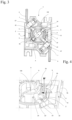
- the electrical cut-off device 1 also subsequently called cut-off device 1 or device 1, according to the invention and as illustrated in figure 1 , has two modules of double cut-off 3, and a manual control module 2 provided with a handle 4. These three modules are superimposed along a central axis A, and held together by complementary interlocking shapes and fixing members (not shown).
- Each cut-off module 3 can have a defined cut-off capacity, for example equal to 750V, thus making it possible to have, in the example illustrated, a device 1 capable of cutting a voltage of 1500V, without this example being limiting.
- the cut-off modules 3 are preferably identical and only one cut-off module 3 will be described subsequently.
- the cut-off module 3 comprises a non-magnetic and electrically insulating housing 5, in which are housed at least two fixed contacts CF and one movable contact CM.
- the housing 5 is preferably made of two nestable parts 5a, 5b, delimiting between them housings to receive the various components of said cut-off module and simultaneously ensure their positioning, their maintenance and their electrical insulation.
- the fixed contacts CF are connected to external conductors 6 by screw cages 7, or any other type of suitable connection terminal.
- the movable contact CM is a rotary contact, embedded on an electrically insulated rotary pin 8.
- the rotary pin 8 is driven in reciprocating rotation about the central axis A by a snap-action mechanism (not shown) provided in the control module 2.
- the snap-action mechanism forming part of the control module 2 is also not the subject of the invention and will not be described. Any type of control module 2 and snap-action mechanism can therefore be suitable for the cut-off module 3 which is the subject of the invention.
- the fixed contacts CF and the movable contact CM define between them respectively two cut-off zones Z, in which an electric arc E extends, in particular when the electric circuit is opened.
- the electric arc E is represented schematically by a cord in the Figures 5 to 7 and only in the Z-cut zone on the right of the figures.
- the Z-cut zones are, in the example, shown diametrically opposite. They extend in said cutting plane P, in which the electric arc E is inscribed at its birth.
- the cut-off module 3 comprises two cut-off chambers 9, which are in particular delimited by the inner walls of the housing 5 and each comprise one of the cut-off zones Z.
- the cut-off chambers 9 make it possible to manage the electric arc E in order to cut off the current.
- the cut-off chambers 9 are diametrically opposed with respect to the central axis A and symmetrical with respect to the median plane coincident with the cut-off plane P. This example is not limiting, since asymmetric cut-off chambers can be envisaged, without calling into question either the operation or the non-polarity of the magnetic blow-off devices 10.
- the cut-off module 3 further comprises a magnetic blowing device 10 for the electric arc E.
- the magnetic blowing device 10 comprises two static magnetic field sources 11, each arranged near and facing a cut-off zone Z. The fact that each is located facing a cut-off zone Z makes it possible to create a maximum magnetic field directly in the cut-off zone and a quasi-constant magnetic field throughout the cut-off chamber 9 for optimal magnetic blowing of the electric arc E.
- the magnetic field sources 11 are isolated from said cut-off zone Z by internal walls of the housing 5.
- each magnetic field source 11 is oriented to generate a magnetic excitation vector M substantially parallel to the cut-off plane P.
- each magnetic field source 11 moves and stretches the corresponding electric arc E in a direction substantially perpendicular to the cut-off plane P towards the bottom of the parts 5a, 5b of the housing. 5, and this independently in one direction or the other depending on the polarity of the magnetic field source 11 and/or said current.
- the invention is also suitable for magnetic blowing devices which may have a different architecture, proposing a cut-off as both unpolarized and polarized, and blowing the electric arc towards other walls of the housing 5.
- the magnetic field source 11 may consist of one or more permanent magnets, or any other equivalent system capable of generating a magnetic excitation vector, such as one or more electrically powered coils.
- the magnetic field source 11 consists of a permanent magnet, of flat, parallelepipedal shape, without this shape being limiting.
- the numerical reference 11 will be used indifferently to designate the magnetic field source and the magnet(s). Indeed, it is possible to produce a magnetic field source 11 whose shape is adapted to the architecture of the cut-off module, which may be curved in the case for example of a rotary cut-off device.
- it may consist of a plurality of parallelepipedal permanent magnets, arranged side by side on a curved line, or of a permanent magnet molded in a curved shape.
- the characteristics of the permanent magnet, as well as its technical effects on the blowing and stretching of the electric arc are notably described in the publication FR 3 006 101 A1 of the applicant, and will not be detailed in this application.
- the magnetic blowing device 10 differs from that described in the publication mentioned above, by the presence in said extinguishing chamber 9, of a non-magnetic and electrically insulating deflector 20.
- This deflector 20 is designed and arranged to occupy, fill or fill the majority of the extinguishing chamber 9, that is to say the space existing between the extinguishing zone Z and the housing 5, and to provide one or more narrow spaces or intervals between the insulating walls of said deflector and those of said housing.
- the deflector 20 thus forms a completely non-magnetic physical obstacle, interposed on the path of the blown electric arc and reduces to its minimum the volume of air remaining in said extinguishing chamber 9.
- At least one of the remaining narrow spaces or intervals then constitutes an arc confinement zone 21, in which the electric arc E when it is blown magnetically is deflected and constrained to promote its cooling and extinction.
- This arc confinement zone 21 is mainly located at a distance and at right angles to or vertically above the cut-off zone Z in the direction of the electromotive force F.
- figure 7 illustrates the arc confinement zones 21 obtained thanks to the presence of the deflector 20 located mainly between the bottom of the parts 5a, 5b of the housing 5 and the corresponding ends of the ears 22 of the deflector 20.
- the arc confinement zone(s) 21 may be located elsewhere, between the corresponding side or transverse walls of said deflector 20 and said housing 5.
- the deflector 20 is movable, and is an integral part of the movable contact CM, and therefore of the rotating pin 8. It has a C-shaped section, symmetrical with respect to the cut-off plane P. It comprises two ears 22 separated by a central opening 23. The central opening 23 frees a passage for the relative movement of the fixed contact CF with respect to the movable contact CM in the cut-off plane P.
- the deflector 20 comprises a shoulder 24 between the ears 22 and the rotating pin 8, which delimits with the housing 5 a groove for guiding the rotation of said rotating pin 8.
- the shape of the deflector 20 and that of the means for guiding the rotation of the rotating pin 8 may be different depending on the architecture of the cut-off module 3.
- the deflector 20 is constituted in this example by a plurality of fins 25, for example five fins 25, without this number being limiting.
- the fins 25 are oriented perpendicular to the cutting plane P. They are distributed in the cutting zone Z, which extends over an angular sector, in the case of a rotary cutting module.
- the interval between two consecutive fins 25 is regular, but could be irregular. This exemplary embodiment is therefore not limiting.
- the inner walls of the housing 5 have a shape substantially complementary to the shape of the deflector 20, for example to that of the ears 22, with a clearance determined to create said arc confinement zones 21.
- the inner walls of the housing 5 also have a substantially symmetrical geometric shape with respect to the cut-off plane P in the illustrated example, without this example being limiting.
- the symmetry of the interrupting chambers 9 with respect to said cut-off plane P makes it possible to guarantee equivalent cut-off performances, whatever the polarity of the magnets 11 and the direction of the current, if the magnets are also arranged symmetrically with respect to said cut-off plane P.
- the same result is possible in the event of non-symmetry of the interrupting chambers 9, if the magnets 11 are also arranged non-symmetrically. In all cases, the non-polarized operation of the magnetic blowing device 10 is guaranteed.
- the deflector 20 interposed on the path of the blown electric arc E forms a non-magnetic physical obstacle which has the effect of immediately deflecting the path of the plasma of the arc in the direction of the electromotive force F, up to the confinement zone 21 between the end of the ears 22 of the deflector 20 and the housing 5.
- the gaps existing between the fins 25 of the deflector 20 on the one hand, and between the deflector 20 and the inner walls of the housing 5 on the other hand form unidirectional exhaust columns promoting the expansion of the arc plasma towards the confinement zone 21 and its cooling in contact with the insulating walls of the deflector 20 and the housing 5.
- the electric arc E is stretched, elongated and clamped between the corresponding insulating walls of the housing 5 and the deflector 20.
- the electric arc E then cools abruptly.
- This cooling technique is particularly rapid and very effective.
- the electrically insulating materials constituting the housing 5 and the deflector 20 are preferably non-magnetic materials which do not produce any effect on the magnetic field generated by the magnets 11 and do not disturb the magnetic blowing of the arc in any way. These materials can further improve the technical effect described above, in particular if they have gas-forming properties.
- These may be thermoplastic materials, such as Teflon ® or similar, which, upon contact with the electric arc E, release hydrogen particles, which will mix with the arc plasma and accelerate its cooling.
- This new cutting principle allows a gain in cutting performance because it allows a high arc voltage to be achieved. It also allows the necessary magnetic field to be reduced and lower quality and lower cost magnets to be used, such as ferrite or similar type magnets, instead of high quality magnets made of rare and expensive metals, such as Neodymium Iron Boron.
- the movable deflector 20 as described with reference to Figures 2 to 7 is formed of fins 25 embedded or securely connected to the rotating pin 8 of the movable contact CM.
- the deflector 20 is made up of a solid single-piece part 26, also mobile and integral with the rotating pin 8 of the movable contact CM.
- This solid single-piece part 26 may have a geometry similar to that of the fins 25, i.e. a C-shaped section symmetrical with respect to the cut-off plane P. It thus comprises two ears 22, a central opening 23 and a guide shoulder 24.
- lateral clearance between the deflector 20 and the inner walls of the housing 5 is necessary to create unidirectional exhaust columns promoting the expansion of the arc plasma towards the confinement zones 21 and consequently the displacement and stretching of the electric arc E perpendicular to the cut-off plane P into these arc confinement zones 21.
- the deflector 20 may also be ... openwork, not shown, provided with slots, orifices or the like allowing the passage of the arc plasma.
- THE figures 8 to 10 illustrate another variant embodiment of a deflector 20' which is fixed and attached or securely connected to the housing 5.
- the deflector 20' is made up of a plurality of individual C-shaped plates 24', symmetrical with respect to the cut-off plane P and attached in lateral grooves 25' provided on an inner wall of the housing 5, opposite the cut-off zones Z.
- the deflector 20' is made up in this example of five plates 24', without this number being limiting.
- the plates 24' are oriented perpendicular to the cut-off plane P. They are distributed in the cut-off zone Z, which extends over an angular sector, in the case of a rotary cut-off module.
- the interval between two consecutive plates 24' is regular, but could be irregular. This exemplary embodiment is therefore not limiting.
- the intervals between the plates 24' of the deflector 20' form unidirectional exhaust columns promoting the expansion of the arc plasma in the direction of the electromotive force F and towards the confinement zones 21'.
- deflectors 20, 20' are of course not limiting and other embodiments and/or geometric shapes are possible insofar as they form non-magnetic physical obstacles on the path of the blown electric arc E, which occupy and fill the interrupting chambers 9 to reduce to a minimum the volume of air remaining in narrow spaces, baffles and/or exhaust columns, having the effect of constraining and deflecting the path of the arc plasma and therefore of the electric arc between non-conductive walls.
- the deflector 20, 20' may also consist of a single-piece perforated part, not shown, for example crossed by slots, orifices, pores or the like to allow the expansion of the arc plasma in the direction of the electromotive force F and in the direction of the confinement zones 21, 21'.
- the cutting principle of the invention also applies to so-called linear 3' cutting modules, as opposed to the rotary 3' cutting modules described above.
- the 3' cut-off module is double and comprises two fixed contacts CF and a movable contact CM mounted on an insulated 8' linear carriage.
- the 8' linear carriage is driven in reciprocating translation along an axis T, by a snap-action mechanism (not shown) provided in a control module (not shown).
- the linear 3' cut-off module has a construction substantially similar to the rotary 3 cut-off module of the Figures 2 to 7 , in the sense that it is symmetrical both with respect to a median plane B perpendicular to the cut-off plane P passing through the axis T, and with respect to said cut-off plane P.
- the symmetry of the module in the two planes P and B is not an obligation, and an asymmetrical design can be envisaged, without calling into question either the operation or the non-polarity of the magnetic blowing devices 10.
- the linear cut-off module 3' further comprises two symmetrical cut-off chambers 9, at right angles to two cut-off zones Z, a magnetic blowing device 10 provided with two symmetrical magnets 11 and facing each of the cut-off zones Z, and two symmetrical deflectors 20 embedded on the linear carriage 8'.
- These deflectors 20 further have the same configuration as the deflectors 20 of the Figures 2 to 7 , bear the same numerical references, and are not described again.
- the deflectors 20 fill the cutting chambers 9, and delimit with the interior walls of the housing 5 confinement zones 21 in which the electric arc E is deflected, stretched and constrained when it is magnetically blown by the magnets 11.
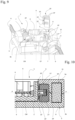
- the magnetic blowing device 10 can be amplified by the addition of a ferromagnetic or similar carcass 12, having the effect of channeling and concentrating the magnetic field M induced by the magnet 11 of the magnetic blowing device 10 in each chamber of cut 9.
- the carcass 12 has a C shape, symmetrical with respect to the cut-off plane P and surrounding the magnet 11 and the deflector 20. It is further isolated from the deflector 20 for an inner wall 5' of the housing 5.
- the shape of the carcass 12 may be different depending on the architecture of the magnetic blowing device 10 and the cut-off module 3, 3'.
- An exemplary embodiment is illustrated with reference to the figure 15 , in which the magnet 11 of the magnetic blowing device 10 is mobile, embedded in the mobile contact CM, and attached or integrated in the rotating spindle 8 or the linear carriage 8'.
- This variant embodiment makes it possible to make the cut-off module 3, 3' more compact and to combine the magnetic effect of a single magnet 11 arranged facing two opposite cut-off zones and blowing the electric arcs E into two opposite cut-off chambers 9.
Landscapes
- Physics & Mathematics (AREA)
- Electromagnetism (AREA)
- Arc-Extinguishing Devices That Are Switches (AREA)
Claims (13)
- Elektrisches Schaltmodul (3, 3'), das mit einer magnetischen Blasvorrichtung (10) ausgestattet ist, wobei das Schaltmodul einen nichtmagnetischen und elektrisch isolierenden Kasten (5) umfasst, in dem mindestens ein fester Kontakt (CF) und ein beweglicher Kontakt (CM) untergebracht sind, wobei der bewegliche Kontakt (CM) so angeordnet ist, dass er sich in Bezug auf den festen Kontakt (CF) zwischen einer geschlossenen Position und einer offenen Position und umgekehrt auf einer Bahn bewegt, mit der eine Trennebene (P) festgelegt ist, wobei der feste Kontakt (CF) und der bewegliche Kontakt (CM) unter sich einen Trennbereich (Z) festlegen, der sich in der Trennebene (P) erstreckt, in der sich ein Lichtbogen (E) bei seiner Entstehung insbesondere bei der Öffnung des Stromkreises erstreckt, wobei das Schaltmodul mindestens eine Schaltkammer (9) umfasst, die von den Innenwänden des Kastens (5) begrenzt wird und den Trennbereich (Z) umfasst, um den Lichtbogen (E) mit dem Ziel der Stromabschaltung zu verwalten, wobei die magnetische Blasvorrichtung (10) mindestens eine Magnetfeldquelle (11) umfasst, die in der Schaltkammer (9) gegenüber dem Trennbereich (Z) angeordnet ist, dadurch gekennzeichnet, dass die mindestens eine Magnetfeldquelle (11) so ausgerichtet ist, dass sie mindestens einen magnetischen Erregungsvektor (M) erzeugt, der im Wesentlichen parallel zur Trennebene (P) verläuft, sodass die induzierte elektromagnetische Kraft (F) den Lichtbogen (E) in einer Richtung bewegt und streckt, die im Wesentlichen senkrecht zu der Trennebene (P) in Richtung des Kastens (5) verläuft, und dass die magnetische Blasvorrichtung (10) ferner mindestens einen nichtmagnetischen und elektrisch isolierenden Detektor (20, 20') umfasst, der in der Schaltkammer (9) angeordnet ist, um ein physikalisches Hindernis auf dem Weg des Lichtbogens (E) zu bilden, wenn er magnetisch geblasen wird,- wobei der Detektor (20, 20') aus einem massiven einteiligen Teil (26) oder einem durchbrochenen einteiligen Teil besteht und der Detektor den größten Teil des Raums einnimmt, der zwischen dem Trennbereich (Z) und dem Kasten (5) in Richtung der elektromagnetischen Kraft (F) vorhanden ist, oder- wobei der Detektor (20, 20') aus einer Vielzahl von Flügeln (25) oder Platten (24') besteht, die voneinander beabstandet sind und im Wesentlichen senkrecht zu der Trennebene (P) in Richtung der elektromagnetischen Kraft (F) ausgerichtet sind, wobei jeder Flügel oder jede Platte den größten Teil des Raums einnimmt, der der Dicke des Flügels oder Platte entspricht und zwischen dem Trennbereich (Z) und dem Kasten (5) in Richtung der elektromagnetischen Kraft (F) vorhanden ist,sodass in dem schmalen Spalt zwischen den isolierenden Wänden des Detektors (20) und den Wänden des Kastens (5) mindestens ein Lichtbogeneinschlussbereich (21, 21') geschaffen wird, in dem der Lichtbogen (E), wenn er magnetisch geblasen wird, abgelenkt und zusammengezogen wird, damit er abgekühlt wird und erlischt.
- Elektrisches Schaltmodul (3, 3') nach Anspruch 1, dadurch gekennzeichnet, dass sich die Schaltkammer (9) an beiden Seiten der Trennebene (P) erstreckt und der Detektor (20, 20') sich auch an beiden Seiten der Trennebene (P) erstreckt, um mindestens zwei Einschlussbereiche (21) zu definieren, die der Trennebene (P) gegenüberliegen.
- Elektrisches Schaltmodul (3, 3') nach Anspruch 2, dadurch gekennzeichnet, dass sich die Schaltkammer (9) symmetrisch zu der Trennebene (P) befindet und der Detektor (20, 20') symmetrisch zu der Trennebene (P) angeordenet ist.
- Elektrisches Schaltmodul (3, 3') nach einem der Ansprüche 1 bis 3, dadurch gekennzeichnet, dass der Detektor (20) beweglich und fest mit dem beweglichen Kontakt (CM) verbunden ist.
- Elektrisches Schaltmodul (3, 3') nach einem der Ansprüche 1 bis 3, dadurch gekennzeichnet, dass der Detektor (20') feststehend und fest mit dem Kasten (5) verbunden ist.
- Elektrisches Schaltmodul (3, 3') nach einem der Ansprüche 1 bis 5, dadurch gekennzeichnet, dass der Detektor (20, 20') einen C-förmigen Querschnitt aufweist, der im Wesentlichen symmetrisch zur Trennebene (P) ist, mit zwei Ösen (22), die durch eine zentrale Öffnung (23) getrennt sind, die so angeordnet ist, dass sie eine Durchführung für die relative Verschiebung des beweglichen Kontakts (CM) oder des festen Kontakts (CF) freigibt, je nachdem, ob der Detektor (20, 20') fest oder beweglich ist.
- Elektrisches Schaltmodul (3, 3') nach einem der Ansprüche 1 bis 6, dadurch gekennzeichnet, dass die Magnetblasvorrichtung (10) mindestens ein Gehäuse (12) umfasst, das so angeordnet ist, dass es den von der mindestens einen Magnetfeldquelle (11) induzierten Magnetfluss (M) kanalisiert.
- Elektrisches Schaltmodul (3, 3') nach Anspruch 7, dadurch gekennzeichnet, dass das Gehäuse (12) in den Kasten (5) integriert ist und mindestens um die Magnetfeldquelle (11) und die Detektoren (20, 20') herum angeordnet ist.
- Elektrisches Schaltmodul (3, 3') nach einem der Ansprüche 1 bis 8, dadurch gekennzeichnet, dass die mindestens eine Feldquelle (11) statisch und fest mit dem Kasten (5) verbunden ist.
- Elektrisches Schaltmodul (3, 3') nach einem der Ansprüche 1 bis 8, dadurch gekennzeichnet, dass die mindestens eine Feldquelle (11) beweglich und fest mit dem beweglichen Kontakt (CM) verbunden ist.
- Elektrisches Schaltmodul (3, 3') nach einem der Ansprüche 1 bis 10, dadurch gekennzeichnet, dass der bewegliche Kontakt (CM) um die Mittelachse (A) drehbar oder parallel zur Trennebene (P) translatorisch beweglich ist.
- Elektrisches Schaltmodul (3, 3') nach einem der Ansprüche 1 bis 11, mit zwei festen Kontakten (CF), die bezüglich einer Mittelachse (A) oder einer Mittelebene (B) des Kastens (5) symmetrisch sind, und einem beweglichen Kontakt (CM), der den beiden festen Kontakten (CF) gemeinsam ist und zwei symmetrische Trennbereiche (Z) definiert, wobei das Schaltmodul zwei symmetrische Schaltkammern (9) umfasst, dadurch gekennzeichnet, dass es außerdem mindestens zwei nichtmagnetische und elektrisch isolierende Detektoren (20, 20') umfasst, die jeweils in einer der Schaltkammern (9) angeordnet sind.
- Elektrisches Schaltgerät (1) mit mindestens einem Steuermodul (2) und einem Schaltmodul (3, 3') nach einem der Ansprüche 1 bis 12.
Applications Claiming Priority (2)
| Application Number | Priority Date | Filing Date | Title |
|---|---|---|---|
| FR2105345A FR3123143A1 (fr) | 2021-05-21 | 2021-05-21 | Module de coupure électrique équipé d’un dispositif de soufflage magnétique et appareil de coupure électrique comportant un tel module |
| PCT/EP2022/062695 WO2022243119A1 (fr) | 2021-05-21 | 2022-05-10 | Module de coupure electrique equipe d'un dispositif de soufflage magnetique et appareil de coupure electrique comportant un tel module |
Publications (3)
| Publication Number | Publication Date |
|---|---|
| EP4341971A1 EP4341971A1 (de) | 2024-03-27 |
| EP4341971B1 true EP4341971B1 (de) | 2025-02-12 |
| EP4341971C0 EP4341971C0 (de) | 2025-02-12 |
Family
ID=76523168
Family Applications (1)
| Application Number | Title | Priority Date | Filing Date |
|---|---|---|---|
| EP22728556.6A Active EP4341971B1 (de) | 2021-05-21 | 2022-05-10 | Elektrisches löschmodul mit einer magnetischen ausblasvorrichtung und elektrisches löschgerät mit einem solchen modul |
Country Status (5)
| Country | Link |
|---|---|
| US (1) | US12125648B2 (de) |
| EP (1) | EP4341971B1 (de) |
| CN (1) | CN117321716B (de) |
| FR (1) | FR3123143A1 (de) |
| WO (1) | WO2022243119A1 (de) |
Families Citing this family (1)
| Publication number | Priority date | Publication date | Assignee | Title |
|---|---|---|---|---|
| FR3162908A1 (fr) * | 2024-05-31 | 2025-12-05 | Safran Electrical & Power | Contacteur électrique comprenant un dispositif d’extinction d’arc électrique par allongement |
Family Cites Families (21)
| Publication number | Priority date | Publication date | Assignee | Title |
|---|---|---|---|---|
| CH394338A (de) * | 1962-01-31 | 1965-06-30 | Bbc Brown Boveri & Cie | Leistungsschalter mit magnetischer Blasung |
| US4401870A (en) * | 1981-11-10 | 1983-08-30 | Hydro-Quebec | Modular suction-gas-cooled magnetic blast circuit breaker |
| FR2583571B1 (fr) * | 1985-06-12 | 1994-02-18 | Merlin Et Gerin | Disjoncteur basse tension a coupure amelioree. |
| JPH09251827A (ja) * | 1996-03-14 | 1997-09-22 | Nissin Electric Co Ltd | 開閉器 |
| EP1191567A1 (de) * | 2000-09-25 | 2002-03-27 | Hager Electro S.A. | Magnetische Blasvorrichtung für Lichtbogen |
| DE102011000763A1 (de) * | 2011-02-16 | 2012-08-16 | Phoenix Contact Gmbh & Co. Kg | Trennvorrichtung |
| EP2590193B1 (de) * | 2011-11-04 | 2014-06-18 | ABB Schweiz AG | Magnetanordnung für einen Niederspannungsschalter |
| DE102011118418B4 (de) * | 2011-11-12 | 2015-07-16 | Ellenberger & Poensgen Gmbh | Schaltsystem |
| EP2600367A1 (de) * | 2011-11-29 | 2013-06-05 | Eaton Industries GmbH | Schaltgerät für Gleichstromanwendungen |
| CN202871728U (zh) * | 2012-11-13 | 2013-04-10 | 安德利集团有限公司 | 一种导弧灭弧装置及使用该导弧灭弧装置的直流断路器 |
| KR101775805B1 (ko) * | 2013-03-27 | 2017-09-06 | 미쓰비시덴키 가부시키가이샤 | 개폐 장치 |
| WO2014170529A1 (en) * | 2013-04-15 | 2014-10-23 | Abb Oy | Electric switch housing |
| US9299509B2 (en) * | 2013-05-23 | 2016-03-29 | Socomec S.A. | Electrical switching device, notably for direct current, equipped with a magnetic module for blowing the electric arc |
| FR3006101B1 (fr) | 2013-05-23 | 2017-03-10 | Socomec Sa | Dispositif de coupure electrique notamment pour courant continu equipe d'un module magnetique pour le soufflage de l'arc electrique |
| FR3027728B1 (fr) * | 2014-10-22 | 2017-12-08 | Socomec Sa | Dispositif de coupure d'arc electrique |
| CN204857636U (zh) * | 2015-05-06 | 2015-12-09 | 北京人民电器厂有限公司 | 一种快速灭弧的灭弧室及应用该灭弧室的小型化断路器 |
| FR3050311B1 (fr) * | 2016-04-15 | 2020-12-04 | Schneider Electric Ind Sas | Disjoncteur electrique a courant continu |
| EP3457422B1 (de) * | 2017-09-15 | 2021-04-14 | ABB Schweiz AG | Elektrischer schalter |
| DE102018204104A1 (de) * | 2018-03-16 | 2019-09-19 | Ellenberger & Poensgen Gmbh | Schalteinheit zur Trennung eines Stromkreises und Schutzschalter |
| EP3561837B1 (de) * | 2018-04-24 | 2022-12-21 | ABB Schweiz AG | Elektrischer schalter |
| CN211719469U (zh) * | 2020-02-27 | 2020-10-20 | 浙江奔一电气有限公司 | 隔离开关的灭弧结构 |
-
2021
- 2021-05-21 FR FR2105345A patent/FR3123143A1/fr not_active Withdrawn
-
2022
- 2022-05-10 WO PCT/EP2022/062695 patent/WO2022243119A1/fr not_active Ceased
- 2022-05-10 CN CN202280033935.2A patent/CN117321716B/zh active Active
- 2022-05-10 US US18/558,254 patent/US12125648B2/en active Active
- 2022-05-10 EP EP22728556.6A patent/EP4341971B1/de active Active
Also Published As
| Publication number | Publication date |
|---|---|
| WO2022243119A1 (fr) | 2022-11-24 |
| CN117321716B (zh) | 2024-06-25 |
| CN117321716A (zh) | 2023-12-29 |
| US20240234043A1 (en) | 2024-07-11 |
| EP4341971A1 (de) | 2024-03-27 |
| US12125648B2 (en) | 2024-10-22 |
| EP4341971C0 (de) | 2025-02-12 |
| FR3123143A1 (fr) | 2022-11-25 |
Similar Documents
| Publication | Publication Date | Title |
|---|---|---|
| EP2061051B1 (de) | Lichtbogenkammer und Schutzschalter, der mit einer solchen Lichtbogenkammer ausgestattet ist | |
| EP3232457B1 (de) | Elektrischer trennschalter für gleichstrom | |
| FR3012662A1 (fr) | Appareil de commutation electrique de courant continu bidirectionnel comportant de petits aimants permanents sur des elements lateraux ferromagnetiques et un ensemble de plaques de sectionnement d'arc | |
| EP1995747A2 (de) | Unterbrechungskammer und Sicherungsautomat, der mit einer solchen Unterbrechungskammer ausgestattet ist | |
| EP2541578B1 (de) | Elektrisches Schutzgerät, das mindestens ein Unterbrechungsmodul umfasst, das von einer Steuervorrichtung mit einer elektromagnetischen Spule gesteuert wird. | |
| EP4341971B1 (de) | Elektrisches löschmodul mit einer magnetischen ausblasvorrichtung und elektrisches löschgerät mit einem solchen modul | |
| EP3210224A1 (de) | Lichtbogensteuerungsvorrichtung | |
| EP2562778A1 (de) | Leistungskontaktvorrichtung zur elektrodynamischen Kompensation bei hohen elektrischen Strömen | |
| FR3141796A1 (fr) | Contacteur électrique à recirculation des gaz ionisés | |
| CH699821B1 (fr) | Coupe-circuit électromécanique et procédé pour couper le courant dans ce coupe-circuit électromécanique. | |
| EP2894647A1 (de) | Unipolarer Abschaltblock und mit einem solchen Block ausgestattete Abschaltvorrichtung | |
| EP0079293B1 (de) | Modulschalter mit magnetischem Blasfluss und mit Gaskühlung | |
| EP0148058A2 (de) | Miniaturlastschalter mit dielektrischen Eigenschaften | |
| FR3016472A1 (fr) | Dispositif de contact electrique et bloc de coupure unipolaire basse tension integrant un tel dispositif de contact electrique | |
| EP4500565B1 (de) | Bidirektionales doppelpoliges doppelbruchschütz mit umgekehrten magnetfeldern | |
| EP1792326B1 (de) | Bistabiler elektromagnetischer aktuator mit integriertem schloss | |
| FR2632772A1 (fr) | Disjoncteur basse tension a soufflage magnetique de l'arc par un aimant permanent | |
| EP4107768B1 (de) | Löschkammer eines magnetischen ausblastyps für eine elektrische bremsvorrichtung und mit einer solchen kammer ausgestattete elektrische bremsvorrichtung | |
| EP2771897B1 (de) | Lichtbogenlöschkammer mit einem rohr zur begrenzung der auswirkungen der partikelerzeugung und elektrische schaltvorrichtung mit einer solchen lichtbogenlöschkammer | |
| FR3006101A1 (fr) | Dispositif de coupure electrique notamment pour courant continu equipe d'un module magnetique pour le soufflage de l'arc electrique | |
| EP2608330A1 (de) | Lüftung für einen Trennschalter | |
| FR2733352A1 (fr) | Pole pour appareil limiteur de courant | |
| FR2977067A1 (fr) | Dispositif de guidage de l'arc dans un appareil de protection electrique et appareil de protection electrique comportant un tel dispositif | |
| WO2023089271A1 (fr) | Chambre de coupure pour courant continu bidirectionnel | |
| EP0646938A1 (de) | Schutzschalter mit verbesserte Lichtbogenkammer |
Legal Events
| Date | Code | Title | Description |
|---|---|---|---|
| STAA | Information on the status of an ep patent application or granted ep patent |
Free format text: STATUS: UNKNOWN |
|
| STAA | Information on the status of an ep patent application or granted ep patent |
Free format text: STATUS: THE INTERNATIONAL PUBLICATION HAS BEEN MADE |
|
| PUAI | Public reference made under article 153(3) epc to a published international application that has entered the european phase |
Free format text: ORIGINAL CODE: 0009012 |
|
| STAA | Information on the status of an ep patent application or granted ep patent |
Free format text: STATUS: REQUEST FOR EXAMINATION WAS MADE |
|
| 17P | Request for examination filed |
Effective date: 20230928 |
|
| AK | Designated contracting states |
Kind code of ref document: A1 Designated state(s): AL AT BE BG CH CY CZ DE DK EE ES FI FR GB GR HR HU IE IS IT LI LT LU LV MC MK MT NL NO PL PT RO RS SE SI SK SM TR |
|
| DAV | Request for validation of the european patent (deleted) | ||
| DAX | Request for extension of the european patent (deleted) | ||
| GRAP | Despatch of communication of intention to grant a patent |
Free format text: ORIGINAL CODE: EPIDOSNIGR1 |
|
| STAA | Information on the status of an ep patent application or granted ep patent |
Free format text: STATUS: GRANT OF PATENT IS INTENDED |
|
| INTG | Intention to grant announced |
Effective date: 20241018 |
|
| GRAS | Grant fee paid |
Free format text: ORIGINAL CODE: EPIDOSNIGR3 |
|
| GRAA | (expected) grant |
Free format text: ORIGINAL CODE: 0009210 |
|
| STAA | Information on the status of an ep patent application or granted ep patent |
Free format text: STATUS: THE PATENT HAS BEEN GRANTED |
|
| AK | Designated contracting states |
Kind code of ref document: B1 Designated state(s): AL AT BE BG CH CY CZ DE DK EE ES FI FR GB GR HR HU IE IS IT LI LT LU LV MC MK MT NL NO PL PT RO RS SE SI SK SM TR |
|
| REG | Reference to a national code |
Ref country code: GB Ref legal event code: FG4D Free format text: NOT ENGLISH |
|
| REG | Reference to a national code |
Ref country code: CH Ref legal event code: EP |
|
| REG | Reference to a national code |
Ref country code: DE Ref legal event code: R096 Ref document number: 602022010558 Country of ref document: DE |
|
| REG | Reference to a national code |
Ref country code: IE Ref legal event code: FG4D Free format text: LANGUAGE OF EP DOCUMENT: FRENCH |
|
| U01 | Request for unitary effect filed |
Effective date: 20250212 |
|
| U07 | Unitary effect registered |
Designated state(s): AT BE BG DE DK EE FI FR IT LT LU LV MT NL PT RO SE SI Effective date: 20250219 |
|
| U20 | Renewal fee for the european patent with unitary effect paid |
Year of fee payment: 4 Effective date: 20250523 |
|
| PG25 | Lapsed in a contracting state [announced via postgrant information from national office to epo] |
Ref country code: RS Free format text: LAPSE BECAUSE OF FAILURE TO SUBMIT A TRANSLATION OF THE DESCRIPTION OR TO PAY THE FEE WITHIN THE PRESCRIBED TIME-LIMIT Effective date: 20250512 |
|
| PG25 | Lapsed in a contracting state [announced via postgrant information from national office to epo] |
Ref country code: PL Free format text: LAPSE BECAUSE OF FAILURE TO SUBMIT A TRANSLATION OF THE DESCRIPTION OR TO PAY THE FEE WITHIN THE PRESCRIBED TIME-LIMIT Effective date: 20250212 |
|
| PG25 | Lapsed in a contracting state [announced via postgrant information from national office to epo] |
Ref country code: ES Free format text: LAPSE BECAUSE OF FAILURE TO SUBMIT A TRANSLATION OF THE DESCRIPTION OR TO PAY THE FEE WITHIN THE PRESCRIBED TIME-LIMIT Effective date: 20250212 |
|
| PG25 | Lapsed in a contracting state [announced via postgrant information from national office to epo] |
Ref country code: NO Free format text: LAPSE BECAUSE OF FAILURE TO SUBMIT A TRANSLATION OF THE DESCRIPTION OR TO PAY THE FEE WITHIN THE PRESCRIBED TIME-LIMIT Effective date: 20250512 Ref country code: IS Free format text: LAPSE BECAUSE OF FAILURE TO SUBMIT A TRANSLATION OF THE DESCRIPTION OR TO PAY THE FEE WITHIN THE PRESCRIBED TIME-LIMIT Effective date: 20250612 |
|
| PG25 | Lapsed in a contracting state [announced via postgrant information from national office to epo] |
Ref country code: HR Free format text: LAPSE BECAUSE OF FAILURE TO SUBMIT A TRANSLATION OF THE DESCRIPTION OR TO PAY THE FEE WITHIN THE PRESCRIBED TIME-LIMIT Effective date: 20250212 |
|
| PG25 | Lapsed in a contracting state [announced via postgrant information from national office to epo] |
Ref country code: GR Free format text: LAPSE BECAUSE OF FAILURE TO SUBMIT A TRANSLATION OF THE DESCRIPTION OR TO PAY THE FEE WITHIN THE PRESCRIBED TIME-LIMIT Effective date: 20250513 |
|
| PG25 | Lapsed in a contracting state [announced via postgrant information from national office to epo] |
Ref country code: SM Free format text: LAPSE BECAUSE OF FAILURE TO SUBMIT A TRANSLATION OF THE DESCRIPTION OR TO PAY THE FEE WITHIN THE PRESCRIBED TIME-LIMIT Effective date: 20250212 |
|
| PG25 | Lapsed in a contracting state [announced via postgrant information from national office to epo] |
Ref country code: CZ Free format text: LAPSE BECAUSE OF FAILURE TO SUBMIT A TRANSLATION OF THE DESCRIPTION OR TO PAY THE FEE WITHIN THE PRESCRIBED TIME-LIMIT Effective date: 20250212 |
|
| PG25 | Lapsed in a contracting state [announced via postgrant information from national office to epo] |
Ref country code: SK Free format text: LAPSE BECAUSE OF FAILURE TO SUBMIT A TRANSLATION OF THE DESCRIPTION OR TO PAY THE FEE WITHIN THE PRESCRIBED TIME-LIMIT Effective date: 20250212 |
|
| PLBE | No opposition filed within time limit |
Free format text: ORIGINAL CODE: 0009261 |
|
| STAA | Information on the status of an ep patent application or granted ep patent |
Free format text: STATUS: NO OPPOSITION FILED WITHIN TIME LIMIT |
|
| REG | Reference to a national code |
Ref country code: CH Ref legal event code: H13 Free format text: ST27 STATUS EVENT CODE: U-0-0-H10-H13 (AS PROVIDED BY THE NATIONAL OFFICE) Effective date: 20251223 |
|
| REG | Reference to a national code |
Ref country code: CH Ref legal event code: L10 Free format text: ST27 STATUS EVENT CODE: U-0-0-L10-L00 (AS PROVIDED BY THE NATIONAL OFFICE) Effective date: 20251224 |
|
| PG25 | Lapsed in a contracting state [announced via postgrant information from national office to epo] |
Ref country code: CH Free format text: LAPSE BECAUSE OF NON-PAYMENT OF DUE FEES Effective date: 20250531 |
|
| 26N | No opposition filed |
Effective date: 20251113 |
|
| PG25 | Lapsed in a contracting state [announced via postgrant information from national office to epo] |
Ref country code: MC Free format text: LAPSE BECAUSE OF FAILURE TO SUBMIT A TRANSLATION OF THE DESCRIPTION OR TO PAY THE FEE WITHIN THE PRESCRIBED TIME-LIMIT Effective date: 20250212 |