EP4339149A1 - Single load lift device - Google Patents
Single load lift device Download PDFInfo
- Publication number
- EP4339149A1 EP4339149A1 EP22881372.1A EP22881372A EP4339149A1 EP 4339149 A1 EP4339149 A1 EP 4339149A1 EP 22881372 A EP22881372 A EP 22881372A EP 4339149 A1 EP4339149 A1 EP 4339149A1
- Authority
- EP
- European Patent Office
- Prior art keywords
- stage
- tray
- lift
- stacking
- unit
- Prior art date
- Legal status (The legal status is an assumption and is not a legal conclusion. Google has not performed a legal analysis and makes no representation as to the accuracy of the status listed.)
- Granted
Links
Images






Classifications
-
- B—PERFORMING OPERATIONS; TRANSPORTING
- B65—CONVEYING; PACKING; STORING; HANDLING THIN OR FILAMENTARY MATERIAL
- B65G—TRANSPORT OR STORAGE DEVICES, e.g. CONVEYORS FOR LOADING OR TIPPING, SHOP CONVEYOR SYSTEMS OR PNEUMATIC TUBE CONVEYORS
- B65G57/00—Stacking of articles
- B65G57/30—Stacking of articles by adding to the bottom of the stack
- B65G57/301—Stacking of articles by adding to the bottom of the stack by means of reciprocatory or oscillatory lifting and holding or gripping devices
- B65G57/302—Stacking of articles by adding to the bottom of the stack by means of reciprocatory or oscillatory lifting and holding or gripping devices added articles being lifted to substantially stationary grippers or holders
-
- B—PERFORMING OPERATIONS; TRANSPORTING
- B66—HOISTING; LIFTING; HAULING
- B66F—HOISTING, LIFTING, HAULING OR PUSHING, NOT OTHERWISE PROVIDED FOR, e.g. DEVICES WHICH APPLY A LIFTING OR PUSHING FORCE DIRECTLY TO THE SURFACE OF A LOAD
- B66F7/00—Lifting frames, e.g. for lifting vehicles; Platform lifts
- B66F7/28—Constructional details, e.g. end stops, pivoting supporting members, sliding runners adjustable to load dimensions
-
- B—PERFORMING OPERATIONS; TRANSPORTING
- B65—CONVEYING; PACKING; STORING; HANDLING THIN OR FILAMENTARY MATERIAL
- B65G—TRANSPORT OR STORAGE DEVICES, e.g. CONVEYORS FOR LOADING OR TIPPING, SHOP CONVEYOR SYSTEMS OR PNEUMATIC TUBE CONVEYORS
- B65G2201/00—Indexing codes relating to handling devices, e.g. conveyors, characterised by the type of product or load being conveyed or handled
- B65G2201/02—Articles
- B65G2201/0235—Containers
- B65G2201/0258—Trays, totes or bins
-
- B—PERFORMING OPERATIONS; TRANSPORTING
- B65—CONVEYING; PACKING; STORING; HANDLING THIN OR FILAMENTARY MATERIAL
- B65G—TRANSPORT OR STORAGE DEVICES, e.g. CONVEYORS FOR LOADING OR TIPPING, SHOP CONVEYOR SYSTEMS OR PNEUMATIC TUBE CONVEYORS
- B65G57/00—Stacking of articles
- B65G57/30—Stacking of articles by adding to the bottom of the stack
- B65G57/301—Stacking of articles by adding to the bottom of the stack by means of reciprocatory or oscillatory lifting and holding or gripping devices
-
- B—PERFORMING OPERATIONS; TRANSPORTING
- B65—CONVEYING; PACKING; STORING; HANDLING THIN OR FILAMENTARY MATERIAL
- B65G—TRANSPORT OR STORAGE DEVICES, e.g. CONVEYORS FOR LOADING OR TIPPING, SHOP CONVEYOR SYSTEMS OR PNEUMATIC TUBE CONVEYORS
- B65G57/00—Stacking of articles
- B65G57/30—Stacking of articles by adding to the bottom of the stack
- B65G57/301—Stacking of articles by adding to the bottom of the stack by means of reciprocatory or oscillatory lifting and holding or gripping devices
- B65G57/303—Stacking of articles by adding to the bottom of the stack by means of reciprocatory or oscillatory lifting and holding or gripping devices the stack being lowered by mobile grippers or holders onto added articles
-
- B—PERFORMING OPERATIONS; TRANSPORTING
- B66—HOISTING; LIFTING; HAULING
- B66F—HOISTING, LIFTING, HAULING OR PUSHING, NOT OTHERWISE PROVIDED FOR, e.g. DEVICES WHICH APPLY A LIFTING OR PUSHING FORCE DIRECTLY TO THE SURFACE OF A LOAD
- B66F2700/00—Lifting apparatus
- B66F2700/09—Other lifting devices
-
- B—PERFORMING OPERATIONS; TRANSPORTING
- B66—HOISTING; LIFTING; HAULING
- B66F—HOISTING, LIFTING, HAULING OR PUSHING, NOT OTHERWISE PROVIDED FOR, e.g. DEVICES WHICH APPLY A LIFTING OR PUSHING FORCE DIRECTLY TO THE SURFACE OF A LOAD
- B66F7/00—Lifting frames, e.g. for lifting vehicles; Platform lifts
- B66F7/02—Lifting frames, e.g. for lifting vehicles; Platform lifts with platforms suspended from ropes, cables, or chains or screws and movable along pillars
Definitions
- the present disclosure relates to a stage-stacking lift.
- Stage-stacking is necessary in order to improve transportation efficiency, but there is a problem that a lift and a stage-stacking unit are separately provided to cause low space efficiency.
- One aspect of the present invention is to provide a stage-stacking lift that may minimize a distribution equipment arrangement space.
- a stage-stacking lift may include a lift unit and a stage-stacking unit mounted in the lift unit.
- the stage-stacking unit may stack a tray, in which accommodation targets are accommodated, in multiple stages, and the lift unit may elevate the tray stacked in multiple stages.
- the stage-stacking unit may be configured to be mountable in the lift unit and thus, minimize the distribution equipment arrangement space.
- the operations of stacking and lifting the trays may become easier and the operating speed may increase.
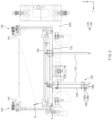
- FIG. 1 is a front view illustrating a stage-stacking lift according to an embodiment of the present invention.
- a horizontally movable unit is omitted in FIG. 1 .
- a stage-stacking lift 1 includes a lift unit 200 and a stage-stacking unit 100 mounted in the lift unit 200.
- the stage-stacking unit 100 stacks a tray 10 in multiple stages, and the lift unit 200 elevates the tray 10 stacked in multiple stages.
- the stage-stacking lift 1 according to an embodiment of the present invention may further include the horizontally movable unit that moves the tray 10 in a horizontal direction, a controller C that controls each of devices, and a tray detection sensor that detects the tray 10.
- FIG. 2 is a plan view of a stage-stacking unit in a stage-stacking lift according to an embodiment of the present invention.
- FIG. 3 is a front view of a stage-stacking unit in a stage-stacking lift according to an embodiment of the present invention.
- the stage-stacking unit 100 may stack the tray 10 in multiple stages, which is mounted in the lift unit 200 and in which accommodation targets are accommodated.
- the accommodation targets may be, for example, multiple secondary batteries.
- the stage-stacking unit 100 may stack the tray 10 in two stages.
- the stage-stacking unit 100 may include a Z-axis movable part M, which moves the tray 10 in a Z-axis direction that is a vertical direction, and a position fixing part 140 which fixes a position of the tray 10 that has moved vertically.
- the stage-stacking unit 100 may further include a height detection sensor 138, and a stage-stacking frame 110 that supports each of components of the stage-stacking unit 100.
- the Z-axis movable part M, the position fixing part 140, and the height detection sensor 138 may be supported by the stage-stacking frame 110.
- the Z-axis movable part M may include a support stage 120 that supports a lower portion of the tray 10, and a vertically movable means 130 that moves the support stage 120 vertically.
- the support stage 120 may move the tray 10 upward while moving upward.
- the vertically movable means 130 may vertically move multiple movable rods 131, which support a lower portion of the support stage 120, to move the support stage 120 vertically.
- a moving method using an actuator 142 or a moving method using a rack and pinion may be used as the method of vertically moving the movable rods 131.
- the present invention is not necessarily limited thereto, and various methods of vertically moving the movable rods 131 may be used.
- a rack screw part may be provided on outer circumference of each of the movable rods 131, and the rack screw part may be engaged with a pinion gear 134 so that the movable rod 131 may move vertically according to rotation of the pinion gear 134.
- the pinion gear 134 may be connected to a driving gear 136 through a power transmission means 135 and receive torque, and the driving gear 136 may be coupled to a rotary shaft of a driving motor 137 and rotate by the driving motor 137.
- the power transmission means 135 may be a belt or a chain.
- the height detection sensor 138 may detect the height of the support stage 120.
- the height detection sensor 138 may detect a moving position of the movable rod 131, which supports the lower portion of the support stage 120, so as to detect the height of the support stage 120.
- the height detection sensor 138 may be mounted in a sensor rod 139, which extends downward from the stage-stacking frame 110, and disposed at a position spaced a predetermined distance from the movable rod 131 in a lateral direction.
- the height detection sensor 138 may include a Z-axis origin sensor 138a, and multiple Z-axis over sensors 138b disposed above and below the Z-axis origin sensor 138a.
- the height detection sensor 138 may detect the height of a detection terminal 138c disposed on the outer circumference of the movable rod 131 so as to detect the moving position of the movable rod 131.
- a position of the detection terminal 138c, which is detected through the Z-axis origin sensor 138a and the Z-axis over sensors 138b, may be detected to detect the height of the support stage 120.
- the controller C to be described later controls the vertically movable means 130 by detecting the position of the movable rod 131 through the height detection sensor 138, the vertical movement of the support stage 120 may be controlled.
- the position fixing part 140 may include a fitting bar 141, which has an end fitted into a groove 10a defined in a side surface of the tray 10, and the actuator 142 which moves the fitting bar 141 forward and backward with respect to a Y-axis.
- the position fixing part 140 may further include a connecting bar 143 that connects the actuator 142 and the fitting bar 141 to each other.
- the fitting bar 141 when the tray 10 moves upward to a predetermined height, the fitting bar 141 may be fitted into the groove 10a defined in the side surface of the tray 10, and support the tray 10 so as to fix the position of the tray 10. That is, the actuator 142 may operate to move the fitting bar 141 through the connecting bar 143, and the fitting bar 141 may be fitted into the groove 10a defined in the side surface of the tray 10 so as to fix the height of the tray 10.
- the position fixing part 140 may be disposed at each of both sides of the tray 10 so as to support each of the both sides of the tray 10 and fix the position thereof.
- the position fixing part 140 may be disposed at each of the both sides of the tray 10 in a Y-axis direction.
- the fitting bar 141 may have a shape extending in the form of a bar in an X-axis direction.
- the fitting bar 141 may have, for example, a rectangular prism shape.
- the position fixing part 140 may further include a fixing part frame 144 that supports the actuator 142 and the fitting bar 141.
- the actuator 142 and the fitting bar 141 may be mounted in an upper portion of the fixing part frame 144.
- the fixing part frame 110 may have a lower portion mounted in the stage-stacking frame 110.
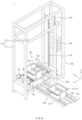
- FIG. 4 is a plan view illustrating a stage-stacking unit and a lift unit in a stage-stacking lift according to an embodiment of the present invention.
- FIG. 5 is a front view illustrating a stage-stacking unit and a lift unit in a stage-stacking lift according to an embodiment of the present invention.
- the lift unit 200 may elevate the tray 10 stacked in multiple stages through the stage-stacking unit 100.
- the lift unit 200 may elevate the tray 10 stacked in the stage-stacking unit 100 by elevating the stage-stacking unit 100.
- the lift unit 200 may include a mounting stage 220 in which the stage-stacking unit 100 is mounted, and a lift means 230 that moves the mounting stage 220 vertically.
- the lift unit 200 may further include a stopper part 260 that prevents dropping of the tray.
- the lift unit 200 may further include a lift frame 210, and the lift frame 210 may include multiple vertical frames 211 and horizontal frames 212.
- the mounting stage 220 may move slidably along the vertical frames 211 through the lift means 230.
- the lift means 230 includes a lift chain 231 to which the mounting stage 220 is coupled, a first chain gear 233 and a second chain gear 234 to which both upper and lower sides of the lift chain 231 are coupled, respectively, a rotating part that rotates the first chain gear 233.
- the rotating part may include a revolving chain 235 having one side connected to the first chain gear 233, a driving chain gear 236 connected to the other side of the revolving chain 235, and a lift motor 237 that rotates the driving chain gear 236.
- the lift motor 237 and the driving chain gear 236 may be connected to each other at a right angle, and various methods may be applied in connecting the lift motor 237 and the driving chain gear 236 to each other at a right angle.
- a connecting method such as a bevel gear connection, may be used, but the present invention is not necessarily limited thereto.
- the revolving chain 235 may revolve to move the mounting stage 220 upward. Accordingly, the stage-stacking unit 100 mounted in the mounting stage 220 may move upward, and the tray 10 stacked in multiple stages in the stage-stacking unit 100 may be lifted upward. Meanwhile, when the lift motor 237 rotates the driving chain gear 236 in the other direction, the mounting stage 220 may move downward.
- the lift unit 230 may further include a weight 232 coupled to the lift chain 221.
- the lift chain 231 may have a first portion to which the mounting stage 220 is fixed, and a second portion to which the weight 232 is fixed.
- the weight 232 may have a weight equal or similar to the sum of the weight of the mounting stage 220 and the weight of the stage-stacking unit 100 mounted in the mounting stage 220.
- a difference between the weight of the weight 232 and the sum of the weight of the mounting stage 220 and the weight of the stage-stacking unit 100 mounted in the mounting stage 220 may be 10% or less.
- the difference between the weight of the weight 232 and the sum of the weight of the mounting stage 220 and the weight of the stage-stacking unit 100 mounted in the mounting stage 220 may be 10% or less, and accordingly, the mounting stage 220 in which the stage-stacking unit 100 is mounted may move vertically even with a small force.
- stage-stacking unit 100 may be bolt-coupled to the mounting stage 220 through a bolt V.
- the stage-stacking frame 110 which supports the components of the stage-stacking unit 100, may be screw-coupled and fixed to the mounting stage 220 through the bolt V.
- the stopper part 260 is provided in each of front and rear of the support stage 120 in order to prevent the dropping of the tray 10 when the tray 10 is loaded on the support stage 120.
- the stopper part 260 may be disposed at each of a loading direction I side and an unloading direction O side with respect to the support stage 120 in a direction in which the tray 10 is loaded on the support stage 120, so as to prevent the dropping of the tray 10.
- the stopper part 260 may include a stopper member 261, and stopper moving means 262 and 263 that move the stopper member 261.
- the stopper member 261 may move by the stopper moving means 262 and 263 in an upward-downward direction that is the Z-axis direction.
- the stopper moving means 262 and 263 may each include, for example, an actuator.
- each of the stopper moving means 262 and 263 may have one side portion coupled to the stopper member 261 and the other side portion coupled to the support stage 120 so as to be rotatable upward.
- a tray detection sensor S may detect the tray 10 disposed at the upper portion of the support stage 120.
- the tray detection sensor S may detect the tray 10 disposed at the upper portion of the support stage 120 so as to detect the position and the number of the stacked stages of the tray 10.
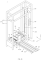
- FIGS. 6 to 11 are conceptual views sequentially illustrating operations during usage of a stage-stacking lift according to an embodiment of the present invention.
- a horizontally movable unit 300 may further include the horizontally movable unit 300 that moves the tray 10 in the X-axis direction that is a horizontal direction.
- the horizontally movable unit 300 may move the tray 10 to the upper portion of the support stage 120.
- the horizontally movable unit 300 may include a guide rail 310 and a conveyor belt 320 mounted in the guide rail 310.
- the tray 10 may have both side portions, each of which is seated on the conveyor belt 320 and moves along movement of the conveyor belt 320 in a lateral direction of the stage-stacking unit 100.
- the controller C may be connected to each of devices of the stage-stacking lift 1 and control an operation of each of the devices.
- the controller C may control an operation of each of the lift unit 200, the stage-stacking unit 100, and the horizontal moving unit 300.
- the controller C controls the vertically movable means 130 of the Z-axis movable part M so that the support stage 120 moves upward to a predetermined height. And, referring to FIGS. 1 and 8 , the controller C controls the position fixing part 140 so that the position of the first tray 11 that has reached the predetermined height is fixed. Thereafter, referring to FIGS. 1 and 9 , the controller C controls the vertically movable means 130 so that the support stage 120 moves to an initial position downward. And, referring to FIGS.
- the controller C controls the horizontally movable unit 300 so that a second tray 12 of the multiple trays 10 moves to the upper portion of the support stage 120, and then, controls the Z-axis movable part M so that the second tray 12 is disposed so as to support a lower portion of the first tray 12. Accordingly, the multiple trays may be stacked in multiple stages. Thereafter, referring to FIGS. 1 and 11 , the controller C may control the lift means 230 of the lift unit 200 so that the mounting stage 220, in which the stage-stacking unit 100 is mounted, moves upward.
- the stage-stacking lift 1 according to an embodiment of the present invention configured as above is configured so that the stage-stacking unit 100 is mountable in the lift unit 200.
- a distribution equipment arrangement space may be minimized.
- the operation of stacking and lifting the trays 10 may become easier and the operating speed may increase.
Landscapes
- Engineering & Computer Science (AREA)
- Mechanical Engineering (AREA)
- Life Sciences & Earth Sciences (AREA)
- Geology (AREA)
- Structural Engineering (AREA)
- Pile Receivers (AREA)
- Stacking Of Articles And Auxiliary Devices (AREA)
- Warehouses Or Storage Devices (AREA)
- De-Stacking Of Articles (AREA)
- Sheets, Magazines, And Separation Thereof (AREA)
Abstract
Description
- The present application claims the benefit of the priority of
Korean Patent Application No. 10-2021-0136138, filed on October 13, 2021 - The present disclosure relates to a stage-stacking lift.
- Stage-stacking is necessary in order to improve transportation efficiency, but there is a problem that a lift and a stage-stacking unit are separately provided to cause low space efficiency.
- There is also a problem that a case, in which the lift and the stage-stacking unit are not separately installable in a space with a limited layout, occurs.
- One aspect of the present invention is to provide a stage-stacking lift that may minimize a distribution equipment arrangement space.
- A stage-stacking lift according to an embodiment of the present invention may include a lift unit and a stage-stacking unit mounted in the lift unit. The stage-stacking unit may stack a tray, in which accommodation targets are accommodated, in multiple stages, and the lift unit may elevate the tray stacked in multiple stages.
- According to the present invention, the stage-stacking unit may be configured to be mountable in the lift unit and thus, minimize the distribution equipment arrangement space. In addition, the operations of stacking and lifting the trays may become easier and the operating speed may increase.
-
-
FIG. 1 is a front view exemplarily illustrating a stage-stacking lift according to an embodiment of the present invention. -
FIG. 2 is a plan view of a stage-stacking unit in a stage-stacking lift according to an embodiment of the present invention. -
FIG. 3 is a front view of a stage-stacking unit in a stage-stacking lift according to an embodiment of the present invention. -
FIG. 4 is a plan view illustrating a stage-stacking unit and a lift unit in a stage-stacking lift according to an embodiment of the present invention. -
FIG. 5 is a front view illustrating a stage-stacking unit and a lift unit in a stage-stacking lift according to an embodiment of the present invention. -
FIGS. 6 to 11 are conceptual views sequentially illustrating operations during usage of a stage-stacking lift according to an embodiment of the present invention. - The above and other aspects, features and other advantages of the present invention will be more clearly understood from the following detailed description taken in conjunction with the accompanying drawings. Note that like elements are designated by like reference numerals as far as possible even if they are shown in different drawings. The present invention may be embodied in different forms and should not be construed as limited to the embodiments set forth herein. Moreover, detailed descriptions related to well-known art will be ruled out in order not to unnecessarily obscure subject matters of the present invention.
-
FIG. 1 is a front view illustrating a stage-stacking lift according to an embodiment of the present invention. Here, a horizontally movable unit is omitted inFIG. 1 . - Referring to
FIG. 1 , a stage-stacking lift 1 according to an embodiment of the present invention includes alift unit 200 and a stage-stacking unit 100 mounted in thelift unit 200. The stage-stacking unit 100 stacks atray 10 in multiple stages, and thelift unit 200 elevates thetray 10 stacked in multiple stages. In addition, the stage-stacking lift 1 according to an embodiment of the present invention may further include the horizontally movable unit that moves thetray 10 in a horizontal direction, a controller C that controls each of devices, and a tray detection sensor that detects thetray 10. -
FIG. 2 is a plan view of a stage-stacking unit in a stage-stacking lift according to an embodiment of the present invention.FIG. 3 is a front view of a stage-stacking unit in a stage-stacking lift according to an embodiment of the present invention. - In more detail, referring to
FIG. 1 to 3 , the stage-stacking unit 100 may stack thetray 10 in multiple stages, which is mounted in thelift unit 200 and in which accommodation targets are accommodated. Here, the accommodation targets may be, for example, multiple secondary batteries. Here, for example, the stage-stacking unit 100 may stack thetray 10 in two stages. - The stage-
stacking unit 100 may include a Z-axis movable part M, which moves thetray 10 in a Z-axis direction that is a vertical direction, and aposition fixing part 140 which fixes a position of thetray 10 that has moved vertically. In addition, the stage-stacking unit 100 may further include aheight detection sensor 138, and a stage-stacking frame 110 that supports each of components of the stage-stacking unit 100. Here, the Z-axis movable part M, theposition fixing part 140, and theheight detection sensor 138 may be supported by the stage-stacking frame 110. - Referring to
FIG. 3 , the Z-axis movable part M may include asupport stage 120 that supports a lower portion of thetray 10, and a vertically movable means 130 that moves thesupport stage 120 vertically. When thetray 10 is disposed at an upper portion of thesupport stage 120 through the Z-axis movable part M, thesupport stage 120 may move thetray 10 upward while moving upward. - The vertically movable means 130 may vertically move multiple
movable rods 131, which support a lower portion of thesupport stage 120, to move thesupport stage 120 vertically. Here, for example, a moving method using anactuator 142 or a moving method using a rack and pinion may be used as the method of vertically moving themovable rods 131. However, the present invention is not necessarily limited thereto, and various methods of vertically moving themovable rods 131 may be used. Here, in the moving method using the rack and pinion, for example, a rack screw part may be provided on outer circumference of each of themovable rods 131, and the rack screw part may be engaged with apinion gear 134 so that themovable rod 131 may move vertically according to rotation of thepinion gear 134. Here, thepinion gear 134 may be connected to adriving gear 136 through a power transmission means 135 and receive torque, and thedriving gear 136 may be coupled to a rotary shaft of a drivingmotor 137 and rotate by thedriving motor 137. Here, the power transmission means 135 may be a belt or a chain. - The
height detection sensor 138 may detect the height of thesupport stage 120. - In addition, the
height detection sensor 138 may detect a moving position of themovable rod 131, which supports the lower portion of thesupport stage 120, so as to detect the height of thesupport stage 120. - Moreover, the
height detection sensor 138 may be mounted in asensor rod 139, which extends downward from the stage-stacking frame 110, and disposed at a position spaced a predetermined distance from themovable rod 131 in a lateral direction. - And the
height detection sensor 138 may include a Z-axis origin sensor 138a, and multiple Z-axis oversensors 138b disposed above and below the Z-axis origin sensor 138a. Here, theheight detection sensor 138 may detect the height of adetection terminal 138c disposed on the outer circumference of themovable rod 131 so as to detect the moving position of themovable rod 131. A position of thedetection terminal 138c, which is detected through the Z-axis origin sensor 138a and the Z-axis oversensors 138b, may be detected to detect the height of thesupport stage 120. Here, as the controller C to be described later controls the verticallymovable means 130 by detecting the position of themovable rod 131 through theheight detection sensor 138, the vertical movement of thesupport stage 120 may be controlled. - The
position fixing part 140 may include afitting bar 141, which has an end fitted into agroove 10a defined in a side surface of thetray 10, and theactuator 142 which moves thefitting bar 141 forward and backward with respect to a Y-axis. Here, theposition fixing part 140 may further include a connectingbar 143 that connects theactuator 142 and thefitting bar 141 to each other. - Here, when the
tray 10 moves upward to a predetermined height, thefitting bar 141 may be fitted into thegroove 10a defined in the side surface of thetray 10, and support thetray 10 so as to fix the position of thetray 10. That is, theactuator 142 may operate to move thefitting bar 141 through the connectingbar 143, and thefitting bar 141 may be fitted into thegroove 10a defined in the side surface of thetray 10 so as to fix the height of thetray 10. - In addition, the
position fixing part 140 may be disposed at each of both sides of thetray 10 so as to support each of the both sides of thetray 10 and fix the position thereof. Here, theposition fixing part 140 may be disposed at each of the both sides of thetray 10 in a Y-axis direction. And thefitting bar 141 may have a shape extending in the form of a bar in an X-axis direction. Here, thefitting bar 141 may have, for example, a rectangular prism shape. - Meanwhile, the
position fixing part 140 may further include afixing part frame 144 that supports theactuator 142 and thefitting bar 141. Here, theactuator 142 and thefitting bar 141 may be mounted in an upper portion of thefixing part frame 144. And the fixingpart frame 110 may have a lower portion mounted in the stage-stackingframe 110. -
FIG. 4 is a plan view illustrating a stage-stacking unit and a lift unit in a stage-stacking lift according to an embodiment of the present invention.FIG. 5 is a front view illustrating a stage-stacking unit and a lift unit in a stage-stacking lift according to an embodiment of the present invention. - Referring to
FIGS. 1 ,4 , and5 , thelift unit 200 may elevate thetray 10 stacked in multiple stages through the stage-stackingunit 100. Here, thelift unit 200 may elevate thetray 10 stacked in the stage-stackingunit 100 by elevating the stage-stackingunit 100. - In addition, the
lift unit 200 may include a mountingstage 220 in which the stage-stackingunit 100 is mounted, and a lift means 230 that moves the mountingstage 220 vertically. When the mountingstage 220 moves upward through the lift means 230, thetray 10 stacked in the stage-stackingunit 100 may move upward. And thelift unit 200 may further include astopper part 260 that prevents dropping of the tray. - Meanwhile, the
lift unit 200 may further include alift frame 210, and thelift frame 210 may include multiplevertical frames 211 andhorizontal frames 212. The mountingstage 220 may move slidably along thevertical frames 211 through the lift means 230. - The lift means 230 includes a
lift chain 231 to which the mountingstage 220 is coupled, afirst chain gear 233 and asecond chain gear 234 to which both upper and lower sides of thelift chain 231 are coupled, respectively, a rotating part that rotates thefirst chain gear 233. Here, the rotating part may include a revolvingchain 235 having one side connected to thefirst chain gear 233, a drivingchain gear 236 connected to the other side of the revolvingchain 235, and alift motor 237 that rotates the drivingchain gear 236. Here, thelift motor 237 and the drivingchain gear 236 may be connected to each other at a right angle, and various methods may be applied in connecting thelift motor 237 and the drivingchain gear 236 to each other at a right angle. For example, a connecting method such as a bevel gear connection, may be used, but the present invention is not necessarily limited thereto. - And, in the lift means 230, when the
lift motor 237 operates to rotate the drivingchain gear 236 in one direction, the revolvingchain 235 may revolve to move the mountingstage 220 upward. Accordingly, the stage-stackingunit 100 mounted in the mountingstage 220 may move upward, and thetray 10 stacked in multiple stages in the stage-stackingunit 100 may be lifted upward. Meanwhile, when thelift motor 237 rotates the drivingchain gear 236 in the other direction, the mountingstage 220 may move downward. - Moreover, the
lift unit 230 may further include aweight 232 coupled to the lift chain 221. Here, thelift chain 231 may have a first portion to which the mountingstage 220 is fixed, and a second portion to which theweight 232 is fixed. - The
weight 232 may have a weight equal or similar to the sum of the weight of the mountingstage 220 and the weight of the stage-stackingunit 100 mounted in the mountingstage 220. Here, for example, a difference between the weight of theweight 232 and the sum of the weight of the mountingstage 220 and the weight of the stage-stackingunit 100 mounted in the mountingstage 220 may be 10% or less. Here, more specifically, for example, the difference between the weight of theweight 232 and the sum of the weight of the mountingstage 220 and the weight of the stage-stackingunit 100 mounted in the mountingstage 220 may be 10% or less, and accordingly, the mountingstage 220 in which the stage-stackingunit 100 is mounted may move vertically even with a small force. - Meanwhile, the stage-stacking
unit 100 may be bolt-coupled to the mountingstage 220 through a bolt V. Here, the stage-stackingframe 110, which supports the components of the stage-stackingunit 100, may be screw-coupled and fixed to the mountingstage 220 through the bolt V. - The
stopper part 260 is provided in each of front and rear of thesupport stage 120 in order to prevent the dropping of thetray 10 when thetray 10 is loaded on thesupport stage 120. - That is, the
stopper part 260 may be disposed at each of a loading direction I side and an unloading direction O side with respect to thesupport stage 120 in a direction in which thetray 10 is loaded on thesupport stage 120, so as to prevent the dropping of thetray 10. - The
stopper part 260 may include astopper member 261, and stopper moving means 262 and 263 that move thestopper member 261. Thestopper member 261 may move by the stopper moving means 262 and 263 in an upward-downward direction that is the Z-axis direction. Here, the stopper moving means 262 and 263 may each include, for example, an actuator. Here, each of the stopper moving means 262 and 263 may have one side portion coupled to thestopper member 261 and the other side portion coupled to thesupport stage 120 so as to be rotatable upward. - A tray detection sensor S may detect the
tray 10 disposed at the upper portion of thesupport stage 120. The tray detection sensor S may detect thetray 10 disposed at the upper portion of thesupport stage 120 so as to detect the position and the number of the stacked stages of thetray 10. -
FIGS. 6 to 11 are conceptual views sequentially illustrating operations during usage of a stage-stacking lift according to an embodiment of the present invention. - Referring to
FIGS. 1 and6 , a horizontallymovable unit 300 may further include the horizontallymovable unit 300 that moves thetray 10 in the X-axis direction that is a horizontal direction. - The horizontally
movable unit 300 may move thetray 10 to the upper portion of thesupport stage 120. - The horizontally
movable unit 300 may include aguide rail 310 and aconveyor belt 320 mounted in theguide rail 310. - The
tray 10 may have both side portions, each of which is seated on theconveyor belt 320 and moves along movement of theconveyor belt 320 in a lateral direction of the stage-stackingunit 100. - The controller C may be connected to each of devices of the stage-stacking
lift 1 and control an operation of each of the devices. Here, the controller C may control an operation of each of thelift unit 200, the stage-stackingunit 100, and the horizontal movingunit 300. - Referring to
FIGS. 1 and7 , when the tray detection sensor S detects that afirst tray 11 of themultiple trays 10 is disposed at the upper portion of thesupport stage 120, the controller C controls the verticallymovable means 130 of the Z-axis movable part M so that thesupport stage 120 moves upward to a predetermined height. And, referring toFIGS. 1 and8 , the controller C controls theposition fixing part 140 so that the position of thefirst tray 11 that has reached the predetermined height is fixed. Thereafter, referring toFIGS. 1 and9 , the controller C controls the verticallymovable means 130 so that thesupport stage 120 moves to an initial position downward. And, referring toFIGS. 1 and10 , the controller C controls the horizontallymovable unit 300 so that asecond tray 12 of themultiple trays 10 moves to the upper portion of thesupport stage 120, and then, controls the Z-axis movable part M so that thesecond tray 12 is disposed so as to support a lower portion of thefirst tray 12. Accordingly, the multiple trays may be stacked in multiple stages. Thereafter, referring toFIGS. 1 and11 , the controller C may control the lift means 230 of thelift unit 200 so that the mountingstage 220, in which the stage-stackingunit 100 is mounted, moves upward. - Accordingly, the stage-stacking
lift 1 according to an embodiment of the present invention configured as above is configured so that the stage-stackingunit 100 is mountable in thelift unit 200. Thus, there is an effect that a distribution equipment arrangement space may be minimized. In addition, the operation of stacking and lifting thetrays 10 may become easier and the operating speed may increase. - Although the present invention has been described with reference to the limited embodiments and drawings, the present invention is not limited thereto and may be variously implemented by those of ordinary skill in the art to which the present invention pertains, within the technical idea of the present invention and an equivalent of the appended claims.
- Moreover, the specific protective scope of the present invention will be clarified by the accompanying claims.
-
- 1: Stage-stacking lift
- 10: Tray
- 100: Stage-stacking unit
- 110: Stage-stacking frame
- 120: Support stage
- 130: Vertically movable means
- 131: Movable rod
- 138: Height detection sensor
- 140: Position fixing part
- 141: Fitting bar
- 142: Actuator
- 143: Connecting bar
- 144: Fixing part frame
- 200: Lift unit
- 210: Lift frame
- 220: Mounting stage
- 230: Lift means
- 300: Horizontally movable unit
- C: Controller
- M: Z-axis movable part
- S: Tray detection sensor
Claims (12)
- A stage-stacking lift comprising:a lift unit; anda stage-stacking unit mounted in the lift unit,wherein the stage-stacking unit stacks a tray in multiple stages, in which accommodation targets are accommodated,wherein the lift unit elevates the tray stacked in multiple stages.
- The stage-stacking lift of claim 1, wherein the stage-stacking unit comprises:a Z-axis movable part configured to move the tray in a Z-axis direction that is a vertical direction;a position fixing part configured to fix a position of the tray that has moved in the vertical direction.
- The stage-stacking lift of claim 2, wherein the Z-axis movable part comprises:a support stage configured to support a lower portion of the tray; anda vertically movable means configured to move the support stage vertically,wherein when the tray is disposed at an upper portion of the support stage through the Z-axis movable part, the support stage moves the tray upward while moving upward.
- The stage-stacking lift of claim 3, wherein the stage-stacking unit further comprises a height detection sensor configured to detect a height of the support stage.
- The stage-stacking lift of claim 3, wherein the position fixing part comprises:a fitting bar having an end fitted into a groove defined in a side surface of the tray; andan actuator configured to move the fitting bar forward and backward with respect to a Y-axis,wherein when the tray moves upward to a predetermined height, the fitting bar is fitted into the groove defined in the side surface of the tray so as to support the tray and fix the position thereof.
- The stage-stacking lift of claim 5, further comprising a tray detection sensor configured to detect the tray disposed at the upper portion of the support stage.
- The stage-stacking lift of claim 6, further comprising a horizontally movable unit configured to move the tray in an X-axis direction that is a horizontal direction,
wherein the horizontally movable unit move the tray to the upper portion of the support stage. - The stage-stacking lift of claim 7, further comprising a controller configured to control an operation of each of the lift unit, the stage-stacking unit, and the horizontally movable unit.
- The stage-stacking lift of claim 8, wherein when the tray detection sensor detects that a first tray of multiple trays is disposed at the upper portion of the support stage, the controller controls the vertically movable means of the Z-axis movable part so that the support stage moves upward to a predetermined height,the controller controls the position fixing part so that a position of the first tray that has reached to the predetermined height is fixed, andthe controller controls the horizontally movable unit so that a second tray of the multiple trays moves to the upper portion of the support stage, and then controls the Z-axis movable part so that the second tray is disposed so as to support a lower portion of the first tray, to stack the multiple trays in multiple stages.
- The stage-stacking lift of claim 9, wherein the lift unit comprises:a mounting stage in which the stage-stacking unit is mounted; anda lift means configured to move the mounting stage vertically,wherein when the mounting stage moves upward through the lift means, the tray stacked in the stage-stacking unit moves upward.
- The stage-stacking lift of claim 10, wherein the stage-stacking unit is bolt-coupled to the mounting stage through a bolt.
- The stage-stacking lift of claim 11, wherein the lift unit further comprises a lift frame,wherein the lift frame comprises multiple vertical frames and horizontal frames,wherein the mounting stage moves slidably along the vertical frames through the lift means.
Applications Claiming Priority (2)
| Application Number | Priority Date | Filing Date | Title |
|---|---|---|---|
| KR1020210136138A KR102958446B1 (en) | 2021-10-13 | 2021-10-13 | Stacking lift device |
| PCT/KR2022/015498 WO2023063745A1 (en) | 2021-10-13 | 2022-10-13 | Single load lift device |
Publications (3)
| Publication Number | Publication Date |
|---|---|
| EP4339149A1 true EP4339149A1 (en) | 2024-03-20 |
| EP4339149A4 EP4339149A4 (en) | 2024-10-16 |
| EP4339149B1 EP4339149B1 (en) | 2025-08-27 |
Family
ID=85987567
Family Applications (1)
| Application Number | Title | Priority Date | Filing Date |
|---|---|---|---|
| EP22881372.1A Active EP4339149B1 (en) | 2021-10-13 | 2022-10-13 | Stage-stacking lift |
Country Status (8)
| Country | Link |
|---|---|
| US (1) | US12344487B2 (en) |
| EP (1) | EP4339149B1 (en) |
| JP (1) | JP7677588B2 (en) |
| KR (1) | KR102958446B1 (en) |
| CN (1) | CN117529444A (en) |
| ES (1) | ES3041832T3 (en) |
| HU (1) | HUE072903T2 (en) |
| WO (1) | WO2023063745A1 (en) |
Families Citing this family (1)
| Publication number | Priority date | Publication date | Assignee | Title |
|---|---|---|---|---|
| KR102600223B1 (en) * | 2023-09-04 | 2023-11-08 | 이정용 | Sequential bidirectional circulation vertical lifter |
Family Cites Families (48)
| Publication number | Priority date | Publication date | Assignee | Title |
|---|---|---|---|---|
| US3172545A (en) * | 1961-01-30 | 1965-03-09 | Foremost Dairies Inc | Case unstacking and conveying apparatus |
| JPS5382989U (en) | 1976-12-11 | 1978-07-08 | ||
| JPS5917421A (en) * | 1982-07-15 | 1984-01-28 | Touhatsu:Kk | Stacker for delivering pallets |
| FR2534569B1 (en) * | 1982-10-19 | 1988-03-11 | Saint Hubert Ind Laitiere | IMPROVEMENT FOR MACHINES FOR LOADING TRANSPORT PALLETS |
| JPS61203009A (en) | 1985-03-04 | 1986-09-08 | Hitachi Ltd | Loading and unloading method by stacker crane and stacker crane |
| US5503516A (en) * | 1987-08-07 | 1996-04-02 | Canon Kabushiki Kaisha | Automatic article feeding system |
| JPH0747377Y2 (en) * | 1989-11-06 | 1995-11-01 | マツダ株式会社 | Palletizing equipment for goods |
| JPH05162855A (en) | 1991-04-30 | 1993-06-29 | Iseki & Co Ltd | Seedling box lift up device |
| JPH054720A (en) | 1991-06-26 | 1993-01-14 | Hightech Seiko Kk | Container stocker device |
| JPH0546807U (en) | 1991-11-28 | 1993-06-22 | 村田機械株式会社 | Automatic warehouse |
| DE4203823C2 (en) | 1992-02-10 | 2001-03-08 | Robert Michaelides | Storage facility |
| JPH0582910U (en) | 1992-04-16 | 1993-11-09 | 村田機械株式会社 | Fixed station |
| JPH0664752A (en) | 1992-08-13 | 1994-03-08 | Matsushita Electric Works Ltd | Loading device |
| JPH07277508A (en) | 1994-04-05 | 1995-10-24 | Kenji Murakami | Container piling-up method and device thereof |
| JP3398502B2 (en) | 1995-02-14 | 2003-04-21 | 松下電器産業株式会社 | Stacking and spreading devices |
| JP3409545B2 (en) | 1995-12-08 | 2003-05-26 | 三菱自動車工業株式会社 | Pallet stacking equipment |
| JP2001019163A (en) | 1999-07-13 | 2001-01-23 | Enutekku:Kk | Device for and method of tiering article group |
| US6283703B1 (en) * | 1999-10-22 | 2001-09-04 | Laurier Incorporated | Automatic conveying apparatus for JEDEC carrier members |
| JP2002249225A (en) | 2001-02-23 | 2002-09-03 | Yazaki Ind Chem Co Ltd | Work stacking device and stacking method using the device |
| JP2004067304A (en) | 2002-08-06 | 2004-03-04 | Daifuku Co Ltd | Article receiving member processing equipment |
| KR100541518B1 (en) | 2003-02-10 | 2006-01-10 | 김성기 | Euroform Automatic Lamination Equipment |
| JP4269222B2 (en) | 2003-09-16 | 2009-05-27 | 村田機械株式会社 | Tray transport system |
| JP4552766B2 (en) * | 2005-06-10 | 2010-09-29 | 株式会社ダイフク | Goods storage facility |
| JP2007137550A (en) | 2005-11-15 | 2007-06-07 | Matsumoto Kogyo Kk | Palletizer |
| KR200410214Y1 (en) | 2005-12-15 | 2006-03-07 | 이요섭 | Euroform loader |
| JP5120869B2 (en) | 2006-09-27 | 2013-01-16 | オークラ輸送機株式会社 | Stacking equipment |
| JP2008303020A (en) | 2007-06-07 | 2008-12-18 | Daito Kogyo Kk | Pallet tower |
| KR100992633B1 (en) * | 2008-08-14 | 2010-11-05 | 기아자동차주식회사 | Tire loading device |
| US9014844B2 (en) * | 2011-12-22 | 2015-04-21 | Amazon Technologies, Inc. | Methods and apparatus for stacking receptacles in materials handling facilities |
| KR20130111905A (en) | 2012-04-02 | 2013-10-11 | 박유석 | Euroform auto loader |
| GB201310125D0 (en) * | 2013-06-06 | 2013-07-24 | Ocado Ltd | Storage and retrieval system |
| KR20150065237A (en) | 2013-12-05 | 2015-06-15 | 명일폼테크주식회사 | Building insulation board loading device |
| JP6679375B2 (en) | 2015-04-07 | 2020-04-15 | キヤノン株式会社 | Parts supply device, robot system, and parts supply method |
| JP6347333B2 (en) * | 2015-06-01 | 2018-06-27 | 株式会社ダイフク | Control method of loading / unloading device in flat storage facility |
| US11167924B2 (en) * | 2015-06-24 | 2021-11-09 | HDS Mercury Inc. | Shelving system and power transfer device |
| MX2017000996A (en) * | 2016-01-20 | 2017-07-19 | Rehrig Pacific Co | Bakery tray stacker. |
| CN106115275B (en) | 2016-08-09 | 2019-04-23 | 广西力源宝科技有限公司 | Ferment the lateral lifting type low level stacking/unstacker of pallet |
| CN106081638B (en) * | 2016-08-09 | 2019-01-22 | 广西力源宝科技有限公司 | Fermentation pallet low level stacking/destacking apparatus and method |
| JP6870517B2 (en) | 2017-07-20 | 2021-05-12 | 株式会社ダイフク | Transport vehicle and transport equipment |
| US10300610B1 (en) * | 2018-02-02 | 2019-05-28 | Amazon Technologies, Inc. | High density container gripping system and method |
| CN108382865A (en) | 2018-04-24 | 2018-08-10 | 深圳市劲拓自动化设备股份有限公司 | A kind of charging tray collection separator |
| SE542952C2 (en) * | 2018-05-25 | 2020-09-22 | Vacaw Ab | Automatic loading of trays into carts |
| CN208683972U (en) * | 2018-09-13 | 2019-04-02 | 南京元稀世特自动化设备有限公司 | High-altitude stack layers device |
| DE102018215780A1 (en) * | 2018-09-18 | 2020-03-19 | Robert Bosch Gmbh | Device and method for handling storage units |
| JP7201549B2 (en) | 2019-07-26 | 2023-01-10 | 井関農機株式会社 | crop harvest vehicle |
| JP7415626B2 (en) * | 2020-02-06 | 2024-01-17 | 村田機械株式会社 | holding device |
| CN214086667U (en) * | 2020-12-30 | 2021-08-31 | 枝江鑫森木业有限公司 | A kind of wooden board automatic stacking device |
| JP7044182B2 (en) | 2021-02-10 | 2022-03-30 | 株式会社ダイフク | Transport vehicle |
-
2021
- 2021-10-13 KR KR1020210136138A patent/KR102958446B1/en active Active
-
2022
- 2022-10-13 US US18/570,298 patent/US12344487B2/en active Active
- 2022-10-13 HU HUE22881372A patent/HUE072903T2/en unknown
- 2022-10-13 WO PCT/KR2022/015498 patent/WO2023063745A1/en not_active Ceased
- 2022-10-13 JP JP2024500607A patent/JP7677588B2/en active Active
- 2022-10-13 CN CN202280043708.8A patent/CN117529444A/en active Pending
- 2022-10-13 ES ES22881372T patent/ES3041832T3/en active Active
- 2022-10-13 EP EP22881372.1A patent/EP4339149B1/en active Active
Also Published As
| Publication number | Publication date |
|---|---|
| EP4339149B1 (en) | 2025-08-27 |
| ES3041832T3 (en) | 2025-11-14 |
| JP7677588B2 (en) | 2025-05-15 |
| HUE072903T2 (en) | 2025-12-28 |
| JP2024525640A (en) | 2024-07-12 |
| US20240270515A1 (en) | 2024-08-15 |
| KR20230052744A (en) | 2023-04-20 |
| US12344487B2 (en) | 2025-07-01 |
| EP4339149A4 (en) | 2024-10-16 |
| CN117529444A (en) | 2024-02-06 |
| KR102958446B1 (en) | 2026-04-28 |
| WO2023063745A1 (en) | 2023-04-20 |
Similar Documents
| Publication | Publication Date | Title |
|---|---|---|
| US8882431B2 (en) | Substrate transfer robot and substrate transfer system | |
| US9610694B2 (en) | Device for handling objects in a glove box | |
| US20150090684A1 (en) | Lifting device and automatic handling system thereof | |
| EP4339149B1 (en) | Stage-stacking lift | |
| WO2012026130A1 (en) | Rack for storing board-like member, equipment for placing board-like member, and method for storing board-like member | |
| WO2014034173A1 (en) | Transferring apparatus | |
| EP4251545B1 (en) | A remotely operated vehicle for handling a storage container on a rail system of an automated storage and retrieval system | |
| CN111038905A (en) | Standing curing system and material storing and taking method thereof | |
| US4664575A (en) | Workpiece transferring apparatus for a robot | |
| US7661920B2 (en) | System and a method for manipulating a cassette used in storage by means of a transfer device | |
| CN210392409U (en) | Intelligent stacking stereoscopic warehouse | |
| CN112846415B (en) | Single truss integrated stacker | |
| EP3704055B1 (en) | An automatically-guided vehicle provided with forks for moving a support structure of tiles | |
| US6352399B1 (en) | Twin tower wafer boat loading system and method | |
| EP3466844A1 (en) | A shuttle for delivering and retrieving goods, a storage system with a shuttle and methods associated therewith | |
| US9764898B2 (en) | Automated warehouse and operation method for same | |
| CN118894471A (en) | A kind of overhead rail forklift | |
| EP4140639B1 (en) | Pallet supply apparatus and mtehod of assembling a pallet supply apparatus | |
| CN111792559B (en) | Force multiplying mechanism and lifting device | |
| JP2011236011A (en) | Automated warehouse | |
| JP2010159118A (en) | Automated warehouse | |
| CN222311617U (en) | A collision prevention detection device for picking and placing products in a stereoscopic warehouse | |
| CN210028826U (en) | Draw case device and material transport robot | |
| JP7067437B2 (en) | Transfer device | |
| CN117755512A (en) | A palletizing and cartoning manipulator and cargo stacking system at an air cargo station |
Legal Events
| Date | Code | Title | Description |
|---|---|---|---|
| STAA | Information on the status of an ep patent application or granted ep patent |
Free format text: STATUS: THE INTERNATIONAL PUBLICATION HAS BEEN MADE |
|
| PUAI | Public reference made under article 153(3) epc to a published international application that has entered the european phase |
Free format text: ORIGINAL CODE: 0009012 |
|
| STAA | Information on the status of an ep patent application or granted ep patent |
Free format text: STATUS: REQUEST FOR EXAMINATION WAS MADE |
|
| 17P | Request for examination filed |
Effective date: 20231215 |
|
| AK | Designated contracting states |
Kind code of ref document: A1 Designated state(s): AL AT BE BG CH CY CZ DE DK EE ES FI FR GB GR HR HU IE IS IT LI LT LU LV MC ME MK MT NL NO PL PT RO RS SE SI SK SM TR |
|
| A4 | Supplementary search report drawn up and despatched |
Effective date: 20240918 |
|
| RIC1 | Information provided on ipc code assigned before grant |
Ipc: B65G 57/30 20060101ALI20240912BHEP Ipc: B66F 7/28 20060101ALI20240912BHEP Ipc: B66F 7/02 20060101AFI20240912BHEP |
|
| DAV | Request for validation of the european patent (deleted) | ||
| DAX | Request for extension of the european patent (deleted) | ||
| GRAP | Despatch of communication of intention to grant a patent |
Free format text: ORIGINAL CODE: EPIDOSNIGR1 |
|
| STAA | Information on the status of an ep patent application or granted ep patent |
Free format text: STATUS: GRANT OF PATENT IS INTENDED |
|
| INTG | Intention to grant announced |
Effective date: 20250606 |
|
| GRAS | Grant fee paid |
Free format text: ORIGINAL CODE: EPIDOSNIGR3 |
|
| GRAA | (expected) grant |
Free format text: ORIGINAL CODE: 0009210 |
|
| STAA | Information on the status of an ep patent application or granted ep patent |
Free format text: STATUS: THE PATENT HAS BEEN GRANTED |
|
| P01 | Opt-out of the competence of the unified patent court (upc) registered |
Free format text: CASE NUMBER: APP_31601/2025 Effective date: 20250701 |
|
| AK | Designated contracting states |
Kind code of ref document: B1 Designated state(s): AL AT BE BG CH CY CZ DE DK EE ES FI FR GB GR HR HU IE IS IT LI LT LU LV MC ME MK MT NL NO PL PT RO RS SE SI SK SM TR |
|
| REG | Reference to a national code |
Ref country code: CH Ref legal event code: EP |
|
| REG | Reference to a national code |
Ref country code: DE Ref legal event code: R096 Ref document number: 602022020466 Country of ref document: DE |
|
| REG | Reference to a national code |
Ref country code: IE Ref legal event code: FG4D |
|
| PGFP | Annual fee paid to national office [announced via postgrant information from national office to epo] |
Ref country code: BE Payment date: 20250922 Year of fee payment: 4 |
|
| PGFP | Annual fee paid to national office [announced via postgrant information from national office to epo] |
Ref country code: FR Payment date: 20250925 Year of fee payment: 4 |
|
| REG | Reference to a national code |
Ref country code: ES Ref legal event code: FG2A Ref document number: 3041832 Country of ref document: ES Kind code of ref document: T3 Effective date: 20251114 |
|
| PGFP | Annual fee paid to national office [announced via postgrant information from national office to epo] |
Ref country code: HU Payment date: 20251127 Year of fee payment: 4 |
|
| REG | Reference to a national code |
Ref country code: HU Ref legal event code: AG4A Ref document number: E072903 Country of ref document: HU |
|
| REG | Reference to a national code |
Ref country code: NL Ref legal event code: MP Effective date: 20250827 |
|
| PG25 | Lapsed in a contracting state [announced via postgrant information from national office to epo] |
Ref country code: IS Free format text: LAPSE BECAUSE OF FAILURE TO SUBMIT A TRANSLATION OF THE DESCRIPTION OR TO PAY THE FEE WITHIN THE PRESCRIBED TIME-LIMIT Effective date: 20251227 |
|
| PGFP | Annual fee paid to national office [announced via postgrant information from national office to epo] |
Ref country code: DE Payment date: 20250922 Year of fee payment: 4 |
|
| PG25 | Lapsed in a contracting state [announced via postgrant information from national office to epo] |
Ref country code: NO Free format text: LAPSE BECAUSE OF FAILURE TO SUBMIT A TRANSLATION OF THE DESCRIPTION OR TO PAY THE FEE WITHIN THE PRESCRIBED TIME-LIMIT Effective date: 20251127 |
|
| REG | Reference to a national code |
Ref country code: LT Ref legal event code: MG9D |
|
| PG25 | Lapsed in a contracting state [announced via postgrant information from national office to epo] |
Ref country code: PT Free format text: LAPSE BECAUSE OF FAILURE TO SUBMIT A TRANSLATION OF THE DESCRIPTION OR TO PAY THE FEE WITHIN THE PRESCRIBED TIME-LIMIT Effective date: 20251229 |
|
| PG25 | Lapsed in a contracting state [announced via postgrant information from national office to epo] |
Ref country code: FI Free format text: LAPSE BECAUSE OF FAILURE TO SUBMIT A TRANSLATION OF THE DESCRIPTION OR TO PAY THE FEE WITHIN THE PRESCRIBED TIME-LIMIT Effective date: 20250827 |
|
| PG25 | Lapsed in a contracting state [announced via postgrant information from national office to epo] |
Ref country code: HR Free format text: LAPSE BECAUSE OF FAILURE TO SUBMIT A TRANSLATION OF THE DESCRIPTION OR TO PAY THE FEE WITHIN THE PRESCRIBED TIME-LIMIT Effective date: 20250827 Ref country code: NL Free format text: LAPSE BECAUSE OF FAILURE TO SUBMIT A TRANSLATION OF THE DESCRIPTION OR TO PAY THE FEE WITHIN THE PRESCRIBED TIME-LIMIT Effective date: 20250827 |
|
| PG25 | Lapsed in a contracting state [announced via postgrant information from national office to epo] |
Ref country code: GR Free format text: LAPSE BECAUSE OF FAILURE TO SUBMIT A TRANSLATION OF THE DESCRIPTION OR TO PAY THE FEE WITHIN THE PRESCRIBED TIME-LIMIT Effective date: 20251128 |
|
| PG25 | Lapsed in a contracting state [announced via postgrant information from national office to epo] |
Ref country code: SE Free format text: LAPSE BECAUSE OF FAILURE TO SUBMIT A TRANSLATION OF THE DESCRIPTION OR TO PAY THE FEE WITHIN THE PRESCRIBED TIME-LIMIT Effective date: 20250827 |
|
| PG25 | Lapsed in a contracting state [announced via postgrant information from national office to epo] |
Ref country code: LV Free format text: LAPSE BECAUSE OF FAILURE TO SUBMIT A TRANSLATION OF THE DESCRIPTION OR TO PAY THE FEE WITHIN THE PRESCRIBED TIME-LIMIT Effective date: 20250827 |
|
| PG25 | Lapsed in a contracting state [announced via postgrant information from national office to epo] |
Ref country code: PL Free format text: LAPSE BECAUSE OF FAILURE TO SUBMIT A TRANSLATION OF THE DESCRIPTION OR TO PAY THE FEE WITHIN THE PRESCRIBED TIME-LIMIT Effective date: 20250827 Ref country code: BG Free format text: LAPSE BECAUSE OF FAILURE TO SUBMIT A TRANSLATION OF THE DESCRIPTION OR TO PAY THE FEE WITHIN THE PRESCRIBED TIME-LIMIT Effective date: 20250827 |
|
| PG25 | Lapsed in a contracting state [announced via postgrant information from national office to epo] |
Ref country code: RS Free format text: LAPSE BECAUSE OF FAILURE TO SUBMIT A TRANSLATION OF THE DESCRIPTION OR TO PAY THE FEE WITHIN THE PRESCRIBED TIME-LIMIT Effective date: 20251127 |
|
| PGFP | Annual fee paid to national office [announced via postgrant information from national office to epo] |
Ref country code: ES Payment date: 20251117 Year of fee payment: 4 |
|
| REG | Reference to a national code |
Ref country code: AT Ref legal event code: MK05 Ref document number: 1829829 Country of ref document: AT Kind code of ref document: T Effective date: 20250827 |
|
| PG25 | Lapsed in a contracting state [announced via postgrant information from national office to epo] |
Ref country code: RO Free format text: LAPSE BECAUSE OF FAILURE TO SUBMIT A TRANSLATION OF THE DESCRIPTION OR TO PAY THE FEE WITHIN THE PRESCRIBED TIME-LIMIT Effective date: 20250827 |
|
| PG25 | Lapsed in a contracting state [announced via postgrant information from national office to epo] |
Ref country code: SM Free format text: LAPSE BECAUSE OF FAILURE TO SUBMIT A TRANSLATION OF THE DESCRIPTION OR TO PAY THE FEE WITHIN THE PRESCRIBED TIME-LIMIT Effective date: 20250827 |
|
| PG25 | Lapsed in a contracting state [announced via postgrant information from national office to epo] |
Ref country code: DK Free format text: LAPSE BECAUSE OF FAILURE TO SUBMIT A TRANSLATION OF THE DESCRIPTION OR TO PAY THE FEE WITHIN THE PRESCRIBED TIME-LIMIT Effective date: 20250827 |
|
| PG25 | Lapsed in a contracting state [announced via postgrant information from national office to epo] |
Ref country code: AT Free format text: LAPSE BECAUSE OF FAILURE TO SUBMIT A TRANSLATION OF THE DESCRIPTION OR TO PAY THE FEE WITHIN THE PRESCRIBED TIME-LIMIT Effective date: 20250827 |
|
| PG25 | Lapsed in a contracting state [announced via postgrant information from national office to epo] |
Ref country code: IT Free format text: LAPSE BECAUSE OF FAILURE TO SUBMIT A TRANSLATION OF THE DESCRIPTION OR TO PAY THE FEE WITHIN THE PRESCRIBED TIME-LIMIT Effective date: 20250827 |
|
| PG25 | Lapsed in a contracting state [announced via postgrant information from national office to epo] |
Ref country code: CZ Free format text: LAPSE BECAUSE OF FAILURE TO SUBMIT A TRANSLATION OF THE DESCRIPTION OR TO PAY THE FEE WITHIN THE PRESCRIBED TIME-LIMIT Effective date: 20250827 |
|
| PG25 | Lapsed in a contracting state [announced via postgrant information from national office to epo] |
Ref country code: EE Free format text: LAPSE BECAUSE OF FAILURE TO SUBMIT A TRANSLATION OF THE DESCRIPTION OR TO PAY THE FEE WITHIN THE PRESCRIBED TIME-LIMIT Effective date: 20250827 Ref country code: SK Free format text: LAPSE BECAUSE OF FAILURE TO SUBMIT A TRANSLATION OF THE DESCRIPTION OR TO PAY THE FEE WITHIN THE PRESCRIBED TIME-LIMIT Effective date: 20250827 |