EP4339088A1 - Verfahren zum betreiben eines elektrofahrrads - Google Patents
Verfahren zum betreiben eines elektrofahrrads Download PDFInfo
- Publication number
- EP4339088A1 EP4339088A1 EP23191235.3A EP23191235A EP4339088A1 EP 4339088 A1 EP4339088 A1 EP 4339088A1 EP 23191235 A EP23191235 A EP 23191235A EP 4339088 A1 EP4339088 A1 EP 4339088A1
- Authority
- EP
- European Patent Office
- Prior art keywords
- torque
- electric bicycle
- controlled generation
- braking
- drive torque
- Prior art date
- Legal status (The legal status is an assumption and is not a legal conclusion. Google has not performed a legal analysis and makes no representation as to the accuracy of the status listed.)
- Granted
Links
Images


Classifications
-
- B—PERFORMING OPERATIONS; TRANSPORTING
- B62—LAND VEHICLES FOR TRAVELLING OTHERWISE THAN ON RAILS
- B62M—RIDER PROPULSION OF WHEELED VEHICLES OR SLEDGES; POWERED PROPULSION OF SLEDGES OR SINGLE-TRACK CYCLES; TRANSMISSIONS SPECIALLY ADAPTED FOR SUCH VEHICLES
- B62M6/00—Rider propulsion of wheeled vehicles with additional source of power, e.g. combustion engine or electric motor
- B62M6/40—Rider propelled cycles with auxiliary electric motor
- B62M6/45—Control or actuating devices therefor
- B62M6/50—Control or actuating devices therefor characterised by detectors or sensors, or arrangement thereof
-
- B—PERFORMING OPERATIONS; TRANSPORTING
- B62—LAND VEHICLES FOR TRAVELLING OTHERWISE THAN ON RAILS
- B62M—RIDER PROPULSION OF WHEELED VEHICLES OR SLEDGES; POWERED PROPULSION OF SLEDGES OR SINGLE-TRACK CYCLES; TRANSMISSIONS SPECIALLY ADAPTED FOR SUCH VEHICLES
- B62M6/00—Rider propulsion of wheeled vehicles with additional source of power, e.g. combustion engine or electric motor
- B62M6/40—Rider propelled cycles with auxiliary electric motor
- B62M6/45—Control or actuating devices therefor
-
- B—PERFORMING OPERATIONS; TRANSPORTING
- B60—VEHICLES IN GENERAL
- B60L—PROPULSION OF ELECTRICALLY-PROPELLED VEHICLES; SUPPLYING ELECTRIC POWER FOR AUXILIARY EQUIPMENT OF ELECTRICALLY-PROPELLED VEHICLES; ELECTRODYNAMIC BRAKE SYSTEMS FOR VEHICLES IN GENERAL; MAGNETIC SUSPENSION OR LEVITATION FOR VEHICLES; MONITORING OPERATING VARIABLES OF ELECTRICALLY-PROPELLED VEHICLES; ELECTRIC SAFETY DEVICES FOR ELECTRICALLY-PROPELLED VEHICLES
- B60L15/00—Methods, circuits, or devices for controlling the traction-motor speed of electrically-propelled vehicles
- B60L15/20—Methods, circuits, or devices for controlling the traction-motor speed of electrically-propelled vehicles for control of the vehicle or its driving motor to achieve a desired performance, e.g. speed, torque, programmed variation of speed
- B60L15/2009—Methods, circuits, or devices for controlling the traction-motor speed of electrically-propelled vehicles for control of the vehicle or its driving motor to achieve a desired performance, e.g. speed, torque, programmed variation of speed for braking
- B60L15/2018—Methods, circuits, or devices for controlling the traction-motor speed of electrically-propelled vehicles for control of the vehicle or its driving motor to achieve a desired performance, e.g. speed, torque, programmed variation of speed for braking for braking on a slope
-
- B—PERFORMING OPERATIONS; TRANSPORTING
- B60—VEHICLES IN GENERAL
- B60L—PROPULSION OF ELECTRICALLY-PROPELLED VEHICLES; SUPPLYING ELECTRIC POWER FOR AUXILIARY EQUIPMENT OF ELECTRICALLY-PROPELLED VEHICLES; ELECTRODYNAMIC BRAKE SYSTEMS FOR VEHICLES IN GENERAL; MAGNETIC SUSPENSION OR LEVITATION FOR VEHICLES; MONITORING OPERATING VARIABLES OF ELECTRICALLY-PROPELLED VEHICLES; ELECTRIC SAFETY DEVICES FOR ELECTRICALLY-PROPELLED VEHICLES
- B60L15/00—Methods, circuits, or devices for controlling the traction-motor speed of electrically-propelled vehicles
- B60L15/20—Methods, circuits, or devices for controlling the traction-motor speed of electrically-propelled vehicles for control of the vehicle or its driving motor to achieve a desired performance, e.g. speed, torque, programmed variation of speed
- B60L15/2072—Methods, circuits, or devices for controlling the traction-motor speed of electrically-propelled vehicles for control of the vehicle or its driving motor to achieve a desired performance, e.g. speed, torque, programmed variation of speed for drive off
- B60L15/2081—Methods, circuits, or devices for controlling the traction-motor speed of electrically-propelled vehicles for control of the vehicle or its driving motor to achieve a desired performance, e.g. speed, torque, programmed variation of speed for drive off for drive off on a slope
-
- B—PERFORMING OPERATIONS; TRANSPORTING
- B60—VEHICLES IN GENERAL
- B60L—PROPULSION OF ELECTRICALLY-PROPELLED VEHICLES; SUPPLYING ELECTRIC POWER FOR AUXILIARY EQUIPMENT OF ELECTRICALLY-PROPELLED VEHICLES; ELECTRODYNAMIC BRAKE SYSTEMS FOR VEHICLES IN GENERAL; MAGNETIC SUSPENSION OR LEVITATION FOR VEHICLES; MONITORING OPERATING VARIABLES OF ELECTRICALLY-PROPELLED VEHICLES; ELECTRIC SAFETY DEVICES FOR ELECTRICALLY-PROPELLED VEHICLES
- B60L50/00—Electric propulsion with power supplied within the vehicle
- B60L50/20—Electric propulsion with power supplied within the vehicle using propulsion power generated by humans or animals
-
- B—PERFORMING OPERATIONS; TRANSPORTING
- B60—VEHICLES IN GENERAL
- B60T—VEHICLE BRAKE CONTROL SYSTEMS OR PARTS THEREOF; BRAKE CONTROL SYSTEMS OR PARTS THEREOF, IN GENERAL; ARRANGEMENT OF BRAKING ELEMENTS ON VEHICLES IN GENERAL; PORTABLE DEVICES FOR PREVENTING UNWANTED MOVEMENT OF VEHICLES; VEHICLE MODIFICATIONS TO FACILITATE COOLING OF BRAKES
- B60T8/00—Arrangements for adjusting wheel-braking force to meet varying vehicular or ground-surface conditions, e.g. limiting or varying distribution of braking force
- B60T8/17—Using electrical or electronic regulation means to control braking
- B60T8/1701—Braking or traction control means specially adapted for particular types of vehicles
- B60T8/1706—Braking or traction control means specially adapted for particular types of vehicles for single-track vehicles, e.g. motorcycles
-
- B—PERFORMING OPERATIONS; TRANSPORTING
- B60—VEHICLES IN GENERAL
- B60T—VEHICLE BRAKE CONTROL SYSTEMS OR PARTS THEREOF; BRAKE CONTROL SYSTEMS OR PARTS THEREOF, IN GENERAL; ARRANGEMENT OF BRAKING ELEMENTS ON VEHICLES IN GENERAL; PORTABLE DEVICES FOR PREVENTING UNWANTED MOVEMENT OF VEHICLES; VEHICLE MODIFICATIONS TO FACILITATE COOLING OF BRAKES
- B60T8/00—Arrangements for adjusting wheel-braking force to meet varying vehicular or ground-surface conditions, e.g. limiting or varying distribution of braking force
- B60T8/17—Using electrical or electronic regulation means to control braking
- B60T8/176—Brake regulation specially adapted to prevent excessive wheel slip during vehicle deceleration, e.g. ABS
- B60T8/1761—Brake regulation specially adapted to prevent excessive wheel slip during vehicle deceleration, e.g. ABS responsive to wheel or brake dynamics, e.g. wheel slip, wheel acceleration or rate of change of brake fluid pressure
-
- B—PERFORMING OPERATIONS; TRANSPORTING
- B60—VEHICLES IN GENERAL
- B60L—PROPULSION OF ELECTRICALLY-PROPELLED VEHICLES; SUPPLYING ELECTRIC POWER FOR AUXILIARY EQUIPMENT OF ELECTRICALLY-PROPELLED VEHICLES; ELECTRODYNAMIC BRAKE SYSTEMS FOR VEHICLES IN GENERAL; MAGNETIC SUSPENSION OR LEVITATION FOR VEHICLES; MONITORING OPERATING VARIABLES OF ELECTRICALLY-PROPELLED VEHICLES; ELECTRIC SAFETY DEVICES FOR ELECTRICALLY-PROPELLED VEHICLES
- B60L2200/00—Type of vehicles
- B60L2200/12—Bikes
-
- B—PERFORMING OPERATIONS; TRANSPORTING
- B60—VEHICLES IN GENERAL
- B60L—PROPULSION OF ELECTRICALLY-PROPELLED VEHICLES; SUPPLYING ELECTRIC POWER FOR AUXILIARY EQUIPMENT OF ELECTRICALLY-PROPELLED VEHICLES; ELECTRODYNAMIC BRAKE SYSTEMS FOR VEHICLES IN GENERAL; MAGNETIC SUSPENSION OR LEVITATION FOR VEHICLES; MONITORING OPERATING VARIABLES OF ELECTRICALLY-PROPELLED VEHICLES; ELECTRIC SAFETY DEVICES FOR ELECTRICALLY-PROPELLED VEHICLES
- B60L2240/00—Control parameters of input or output; Target parameters
- B60L2240/40—Drive Train control parameters
- B60L2240/42—Drive Train control parameters related to electric machines
- B60L2240/423—Torque
-
- B—PERFORMING OPERATIONS; TRANSPORTING
- B60—VEHICLES IN GENERAL
- B60L—PROPULSION OF ELECTRICALLY-PROPELLED VEHICLES; SUPPLYING ELECTRIC POWER FOR AUXILIARY EQUIPMENT OF ELECTRICALLY-PROPELLED VEHICLES; ELECTRODYNAMIC BRAKE SYSTEMS FOR VEHICLES IN GENERAL; MAGNETIC SUSPENSION OR LEVITATION FOR VEHICLES; MONITORING OPERATING VARIABLES OF ELECTRICALLY-PROPELLED VEHICLES; ELECTRIC SAFETY DEVICES FOR ELECTRICALLY-PROPELLED VEHICLES
- B60L2250/00—Driver interactions
- B60L2250/24—Driver interactions by lever actuation
-
- B—PERFORMING OPERATIONS; TRANSPORTING
- B60—VEHICLES IN GENERAL
- B60L—PROPULSION OF ELECTRICALLY-PROPELLED VEHICLES; SUPPLYING ELECTRIC POWER FOR AUXILIARY EQUIPMENT OF ELECTRICALLY-PROPELLED VEHICLES; ELECTRODYNAMIC BRAKE SYSTEMS FOR VEHICLES IN GENERAL; MAGNETIC SUSPENSION OR LEVITATION FOR VEHICLES; MONITORING OPERATING VARIABLES OF ELECTRICALLY-PROPELLED VEHICLES; ELECTRIC SAFETY DEVICES FOR ELECTRICALLY-PROPELLED VEHICLES
- B60L2260/00—Operating Modes
- B60L2260/20—Drive modes; Transition between modes
- B60L2260/22—Standstill, e.g. zero speed
-
- B—PERFORMING OPERATIONS; TRANSPORTING
- B62—LAND VEHICLES FOR TRAVELLING OTHERWISE THAN ON RAILS
- B62J—CYCLE SADDLES OR SEATS; AUXILIARY DEVICES OR ACCESSORIES SPECIALLY ADAPTED TO CYCLES AND NOT OTHERWISE PROVIDED FOR, e.g. ARTICLE CARRIERS OR CYCLE PROTECTORS
- B62J45/00—Electrical equipment arrangements specially adapted for use as accessories on cycles, not otherwise provided for
- B62J45/40—Sensor arrangements; Mounting thereof
- B62J45/41—Sensor arrangements; Mounting thereof characterised by the type of sensor
- B62J45/415—Inclination sensors
- B62J45/4152—Inclination sensors for sensing longitudinal inclination of the cycle
Definitions
- the present invention relates to a method for operating an electric bicycle and an electric bicycle.
- Electric bicycles are known with hydraulic brake systems that have actuators by means of which a brake pressure can be generated in a controlled manner in the brake system.
- actuators can be part of an anti-lock braking system.
- the aim is often to prevent the vehicle's wheels from locking by modulating the hydraulic brake pressure in the system.
- the method involves coordinated control of braking torque and drive torque depending on one another.
- This makes it possible to provide a particularly high level of flexibility when driving the electric bicycle.
- a particularly large torque range when driving the electric bicycle can be covered by the controlled regulation.
- This means that, for example, acceleration or deceleration of the electric bicycle can be achieved flexibly through the corresponding coordinated control of the brake system and drive unit, in particular without the driver having to actively intervene, for example by actuating the brake lever.
- a variety of automatic driving functions can thus be provided in a simple and efficient manner, which enables a particularly high level of driving comfort for the driver of the electric bicycle.
- the actuator of the brake system is actuated in such a way as to generate a predetermined constant braking torque.
- a constant brake pressure is generated in the brake system by means of the actuator.
- This can ensure that a working range of the drive unit is shifted overall towards lower torques.
- a torque range can be covered that allows both acceleration and deceleration of the electric bicycle. For example, by reducing the drive torque Drive unit to a lower value than the constant braking torque generated by the braking system, the deceleration of the electric bicycle can be achieved.
- a particularly simple and effective control can therefore provide a particularly high level of flexibility in the driving operation of the electric bicycle.
- advantageous driving functions can be provided in a simple manner, which can be implemented solely by controlling the drive unit.
- traction control and/or prevention or weakening of the effects of a front wheel of the electric bicycle lifting off can be provided in a particularly simple manner.
- the predetermined constant braking torque corresponds to at least 10%, preferably a maximum of 80%, preferably at least 30%, particularly preferably a maximum of 60%, of a maximum drive torque that can be generated at most by means of the drive unit. This can ensure that a torque range can be covered by solely controlling the drive unit, which also enables sufficient deceleration of the electric bicycle for a variety of driving functions.
- the predetermined constant braking torque is preferably generated independently of a brake lever force on a brake lever of the electric bicycle.
- the brake lever is provided to enable manual generation of brake pressure in the brake system. This means that the constant braking torque is generated in the first operating mode even if there is no actuation of the brake lever.
- a fully automated function can thus be provided, which allows both acceleration and deceleration of the electric bicycle.
- the method further comprises the step: detecting a wheel slip, preferably a driven or drivable wheel of the electric bicycle, in particular a rear wheel.
- the controlled generation of the drive torque, which is provided by the drive unit is carried out depending on the detected wheel slip.
- the drive torque of the drive unit is preferably reduced when the detected wheel slip exceeds a predetermined wheel slip limit value.
- Traction control can be carried out, in particular in order to reduce wheel slip.
- targeted braking of the spinning wheel can be achieved actively and automatically, whereby particularly effective traction control can be provided in a wide variety of driving situations.
- the method further comprises the step: detecting a pitch angle of the electric bicycle.
- a deflection of the electric bicycle about a transverse axis, which can be parallel to a bottom bracket axis, for example, is considered a pitch angle.
- the controlled generation of the drive torque is carried out depending on the detected pitch angle.
- the drive torque of the drive unit is preferably reduced if the detected pitch angle exceeds a predetermined pitch angle limit value. This can, for example, prevent the front wheel of the electric bicycle from lifting off or reduce its impact. This means that wheelie prevention can be provided, for example.
- a change in pitch angle can also be determined, for example, with the drive torque preferably being reduced if the change in pitch angle exceeds a predetermined limit value.
- the controlled generation of the braking torque and the controlled generation of the drive torque take place in such a way as to keep the electric bicycle at a standstill.
- braking torque and drive torque are coordinated in such a way that the electric bicycle is held at a standstill, preferably exclusively by braking torque and drive torque.
- no manual braking or pedal operation by the driver of the electric bicycle is required to keep the electric bicycle at a standstill. This means that a particularly high level of driving comfort can be provided for the driver when operating the electric bicycle.
- the method preferably further comprises the step: detecting an inclination of the electric bicycle, in particular relative to a horizontal.
- the controlled one Generating the braking torque and the controlled generation of the drive torque are carried out depending on the detected inclination. This makes it possible to automatically stop the electric bicycle on an incline or slope in a particularly simple and effective manner.
- the controlled generation of the braking torque and the controlled generation of the drive torque are additionally carried out depending on a total weight of the electric bicycle.
- the total weight is considered to be at least the dead weight of the electric bicycle, and additionally the weight of the driver and the load on the electric bicycle.
- a required drive torque and/or braking torque is determined in order to keep the electric bicycle at a standstill at the corresponding inclination.
- the total weight can be entered manually by the driver of the electric bicycle. This makes it possible in a particularly simple and efficient manner for the electric bicycle to be held on inclines or slopes by the automatic operation of the braking system and drive unit.
- the method further comprises the step: controlled reduction of a brake pressure generated by the brake system in response to a pedal actuation.
- the brake pressure is reduced in such a way that the electric bicycle is accelerated by the drive torque generated by the drive unit. That is, through the coordinated control of drive torque and braking torque, the braking torque being adjusted in particular by reducing the brake pressure, when the driver presses the pedal of the electric bicycle, an automatic starting of the electric bicycle from a standstill, for example on an incline, is initiated .
- the method further comprises the step: detecting a pitch angle of the electric bicycle.
- a deflection of the electric bicycle about a transverse axis, which can be parallel to a bottom bracket axis, for example, is considered a pitch angle.
- the controlled generation of the braking torque and/or the controlled generation of the drive torque is carried out depending on the detected pitch angle.
- the drive torque is reduced and/or the braking torque is increased if the detected pitch angle exceeds a predetermined pitch angle limit value.
- a change in the pitch angle can be determined, with the drive torque preferably being reduced and/or the braking torque increased when the change in the pitch angle exceeds a predetermined limit value. This makes it possible, for example, to prevent a front wheel of the electric bicycle from lifting off in a simple and effective manner, or to mitigate its impact. This means, for example, that wheelie prevention can be provided when starting the electric bicycle.
- the invention leads to an electric bicycle comprising a brake system, preferably a hydraulic brake system, wherein in particular the brake system comprises a controllably operable actuator, a drive unit, which is in particular designed to be controllably actuated, and a control unit which is set up to carry out the method described.
- a brake system preferably a hydraulic brake system
- the brake system comprises a controllably operable actuator, a drive unit, which is in particular designed to be controllably actuated, and a control unit which is set up to carry out the method described.
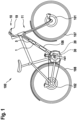
- FIG. 1 shows a simplified schematic view of an electric bicycle 100, in which a method according to a preferred embodiment of the invention is carried out.
- the electric bicycle 100 includes a drive unit 20, which is set up to support a rider's pedaling power using motor power.
- the drive unit 20 is supplied with electrical energy by an electrical energy storage device 106.
- the electric bicycle 100 includes a hydraulic brake system 10 by means of which brakes 101, 102 can be actuated on a front wheel 107 or a rear wheel 108 of the electric bicycle 100.
- the hydraulic brake system 10 includes an anti-lock unit 1, which is also supplied with electrical energy by the electrical energy storage 106.
- the anti-locking unit 1 includes an actuator 5, by means of which a hydraulic brake pressure in the brake system 10 can be changed in a controllable manner.
- a brake pressure in the brake system 10 can be changed by means of the actuator 5 independently of an actuation of a brake lever 19 of the brake system 10. This means that in particular a brake pressure can be built up and thus a braking torque can be generated without the brake lever 19 being actuated.
- a brake pressure in the brake system 10 and thus the braking torque can preferably be reduced even while the brake lever 19 is being operated manually.
- the electric bicycle 100 further comprises a control unit 30, which is set up to carry out the method according to the invention.
- the controlled actuation of the actuator 5 and the controlled actuation of the drive unit 20 can be carried out by means of the control unit 30.
- the method includes at least two operating modes, which can be carried out simultaneously, for example, or alternatively independently of one another.
- a predetermined constant braking torque is generated by means of the brake system 10, preferably while the electric bicycle 10 is traveling.
- a drive torque is generated by means of the drive unit 20 depending on a pedal force manually generated by the driver of the electric bicycle 100.
- FIG. 2 shows a simplified schematic view of torque diagrams 50, 50 'used in carrying out the method according to the preferred embodiment of the invention.
- a torque 51 is shown depending on a speed 52 of the electric bicycle 100.
- Line 55 indicates a torque of zero.
- a first torque diagram 50 in which Figure 2 Left, shows a simplified schematic view of normal operation without carrying out the procedure.
- the two lines 57a show a maximum value and a minimum value of a drive torque that can be generated by the drive unit 20. Between the two lines 57a there is therefore a torque range 57, which can be provided to the drive of the electric bicycle 100 by the controlled actuation of the drive unit 20.
- This torque range 57 extends from the zero line 55 exclusively to positive torques 51.
- This torque range 56 characterizes an optimal range for performing traction control on the rear wheel 108 of the electric bicycle 100.
- the torque range 56 also includes negative torques 51, for example in order to actively brake the rear wheel 108 in the event of a very strong loss of traction.
- the total torque on the electric bicycle 100 which can be provided solely by varying the controlled actuation of the drive unit 20, is shifted in such a way that the second torque range 57 'and the optimal torque for traction control Area 56 are essentially congruent.
- This means that the traction control can be optimally implemented simply by changing the control of the drive unit 20 in an optimal manner and for a particularly wide range of applications.
- a second operating mode of the method is described below with reference to Figure 3 described.
- stopping the electric bicycle 100 on an incline 70 and starting the electric bicycle 100 on the incline 70 can be provided.
- an inclination of the electric bicycle relative to a horizontal 71 is detected.
- the control unit 30 determines which holding force 76 is required to keep the electric bicycle 100 at a standstill on the incline 70.
- the holding force 76 is determined in such a way that it is equal to a downhill force 75, which is based on the inclination and the total weight of the electric bicycle 100.
- the holding force 76 can preferably be provided by the drive torque of the drive unit 20 alone, or alternatively by an additional braking torque of the brake system 10.
- the second operating mode is preferred exclusively during manual actuation of the brake lever 19 of the brake system 10 Electric bike 100 carried out. This means that while the driver has pulled the brake lever 19, the holding force 76 is generated by the appropriately coordinated control of the brake system 10 and the drive unit 20 in order to keep the electric bicycle 100 at a standstill at the incline 70.
- the starting of the electric bicycle 100 can be initiated by reducing the braking torque generated by the braking system 10 in response to a pedal actuation by the driver of the electric bicycle 101 in such a way that the electric bicycle 100 is accelerated by the drive torque of the drive unit 20.
- a propulsive force is generated in the direction of the holding force 76, which is greater than the downhill force 75 in order to accelerate the electric bicycle 100.
- a pitch angle of the electric bicycle 100 can also be detected in both operating modes.
- the coordinated control of braking torque and drive torque can be adjusted in such a way that undesirable driving states with a high pitch angle, so-called “wheelies”, can be avoided or their effects can be reduced.
- a braking torque in particular on the rear wheel 108, can be increased and / or the drive torque of the Drive unit 20 can be reduced.
Landscapes
- Engineering & Computer Science (AREA)
- Transportation (AREA)
- Mechanical Engineering (AREA)
- Chemical & Material Sciences (AREA)
- Combustion & Propulsion (AREA)
- Power Engineering (AREA)
- Physics & Mathematics (AREA)
- Fluid Mechanics (AREA)
- Regulating Braking Force (AREA)
- Electric Propulsion And Braking For Vehicles (AREA)
Abstract
Description
- Die vorliegende Erfindung betrifft ein Verfahren zum Betreiben eines Elektrofahrrads, sowie ein Elektrofahrrad.
- Bekannt sind Elektrofahrräder mit hydraulischen Bremssystemen, die Aktuatoren aufweisen, mittels welchen ein Bremsdruck im Bremssystem gesteuert erzeugt werden kann. Beispielsweise kann ein solcher Aktuator Teil eines Antiblockiersystems sein. Häufig soll dabei durch eine Druckmodulation des hydraulischen Bremsdrucks im System ein Blockieren von Rädern des Fahrzeugs verhindert werden.
- Das erfindungsgemäße Verfahren mit den Merkmalen des Anspruchs 1 zeichnet sich dadurch aus, dass ein besonders flexibler und effizienter Fahrbetrieb des Elektrofahrrads bereitgestellt werden kann. Insbesondere kann dabei ein besonders hoher Fahrkomfort für einen Fahrer des Elektrofahrrads ermöglicht werden. Dies wird erfindungsgemäß erreicht durch ein Verfahren zum Betreiben eines Elektrofahrrads, wobei das Elektrofahrrad ein Bremssystem und eine steuerbar betätigbare Antriebseinheit aufweist, Insbesondere ist die Antriebseinheit eingerichtet, um ein Motordrehmoment im Ansprechen auf eine Pedalbetätigung durch den Fahrer bereitzustellen, um eine Tretkraft des Fahrers motorisch zu unterstützen. Das Bremssystem weist einen steuerbar betätigbaren Aktuator auf, um gesteuert ein Bremsmoment erzeugen zu können. Vorzugsweise ist das Bremssystem als ein hydraulisches Bremssystem ausgebildet. Das Verfahren umfasst die Schritte:
- gesteuertes Erzeugen eines Bremsmoments mittels des Bremssystems, und
- gesteuertes Erzeugen eines Antriebsmoments mittels der Antriebseinheit.
- Mit anderen Worten erfolgt bei dem Verfahren eine koordinierte Regelung von Bremsmoment und Antriebsmoment in Abhängigkeit voneinander. Dadurch kann eine besonders hohe Flexibilität im Fahrbetrieb des Elektrofahrrads bereitgestellt werden. Beispielsweise kann dadurch ein besonders großer Drehmoment-Bereich im Fahrbetrieb des Elektrofahrrads durch die gesteuerte Regelung abgedeckt werden. Das heißt, es kann beispielsweise flexibel eine Beschleunigung oder eine Verzögerung des Elektrofahrrads durch die entsprechende koordinierte Steuerung von Bremssystem und Antriebseinheit erreicht werden, insbesondere ohne dass ein aktiver Eingriff des Fahrers erforderlich ist, beispielsweise mittels einer Bremshebelbetätigung. Somit können eine Vielzahl an automatischen Fahrfunktionen auf einfache und effiziente Weise bereitgestellt werden, wodurch ein besonders hoher Fahrkomfort für den Fahrer des Elektrofahrrads ermöglicht werden kann.
- Die Unteransprüche haben bevorzugte Weiterbildungen der Erfindung zum Inhalt.
- Bevorzugt wird in einem ersten Betriebsmodus der Aktuator des Bremssystems derart betätigt, um ein vorbestimmtes konstantes Bremsmoment zu erzeugen. Das heißt, insbesondere wird mittels des Aktuator ein konstanter Bremsdruck im Bremssystem erzeugt. Dadurch kann erreicht werden, dass ein Arbeitsbereich der Antriebseinheit insgesamt hin zu niedrigeren Drehmomenten verschoben wird. Das heißt, es kann alleine durch Anpassung des mittels der Antriebseinheit bereitstellbaren Antriebsmoments ein Drehmomentbereich abgedeckt werden, der sowohl eine Beschleunigung, als auch eine Verzögerung des Elektrofahrrads zulässt. Beispielsweise kann hierbei durch Reduktion des Antriebsmoments der Antriebseinheit auf einen niedrigeren Wert als das mittels des Bremssystems erzeugte konstante Bremsmoment die Verzögerung des Elektrofahrrads erreicht werden. Somit kann durch eine besonders einfache und effektive Regelung eine besonders hohe Flexibilität im Fahrbetrieb des Elektrofahrrads bereitgestellt werden. Insbesondere können auf einfache Weise vorteilhafte Fahrfunktionen bereitgestellt werden, welche alleine durch die Steuerung der Antriebseinheit umgesetzt werden können. Beispielsweise kann dadurch auf besonders einfache Weise eine Traktionskontrolle und/oder Verhinderung oder ein Abschwächen der Auswirkungen eines Abhebens eines Vorderrades des Elektrofahrrads bereitgestellt werden.
- Besonders bevorzugt entspricht das vorbestimmte konstante Bremsmoment mindestens 10 %, vorzugsweise maximal 80 %, bevorzugt mindestens 30 %, besonders bevorzugt maximal 60 %, eines Maximal-Antriebsmoments, welches maximal mittels der Antriebseinheit erzeugbar ist. Damit kann sichergestellt werden, dass durch die alleinige Steuerung der Antriebseinheit ein Drehmomentbereich abgedeckt werden kann, der auch eine ausreichende Verzögerung des Elektrofahrrads für vielfältige Fahrfunktionen ermöglicht.
- Vorzugsweise erfolgt das Erzeugen des vorbestimmten konstanten Bremsmoments unabhängig von einer Bremshebelkraft an einem Bremshebel des Elektrofahrrads. Insbesondere ist der Bremshebel vorgesehen, um eine manuelle Erzeugung eines Bremsdruck im Bremssystem zu ermöglichen. Das heißt, das konstante Bremsmoment wird im ersten Betriebsmodus auch dann erzeugt, wenn keine Betätigung des Bremshebels vorliegt. Somit kann eine vollständig automatisierte Funktion bereitgestellt werden, welche sowohl eine Beschleunigung als auch eine Verzögerung des Elektrofahrrads erlaubt.
- Weiter bevorzugt umfasst das Verfahren ferner den Schritt: Erfassen eines Radschlupfes, vorzugsweise eines angetriebenen bzw. antreibbaren Rads des Elektrofahrrads, insbesondere eines Hinterrads. Das gesteuerte Erzeugen des Antriebsmoments, das mittels der Antriebseinheit bereitgestellt wird, wird dabei in Abhängigkeit des erfassten Radschlupfes durchgeführt. Bevorzugt wird das Antriebsmoment der Antriebseinheit reduziert, wenn der erfasste Radschlupf einen vorbestimmten Radschlupf-Grenzwert überschreitet. Mit anderen Worten kann durch das entsprechende gesteuerte Betätigen der Antriebseinheit eine Traktionskontrolle durchgeführt werden, insbesondere derart, um den Radschlupf zu reduzieren. Insbesondere in Kombination mit einem durch das Bremssystem erzeugten konstanten Bremsdruck kann dabei aktiv und automatisch ein gezieltes Abbremsen des durchdrehenden Rades erreicht werden, wodurch eine besonders effektive Traktionskontrolle in verschiedensten Fahrsituationen bereitgestellt werden kann.
- Besonders bevorzugt umfasst das Verfahren ferner den Schritt: Erfassen eines Nickwinkels des Elektrofahrrads. Als Nickwinkel wird insbesondere eine Auslenkung des Elektrofahrrads um eine Querachse, welche beispielsweise parallel zu einer Tretlagerachse sein kann, angesehen. Das gesteuerte Erzeugen des Antriebsmoments wird dabei in Abhängigkeit des erfassten Nickwinkels durchgeführt. Bevorzugt wird dabei das Antriebsmoment der Antriebseinheit reduziert, wenn der erfasste Nickwinkel einen vorbestimmten Nickwinkel-Grenzwert überschreitet. Dadurch kann beispielsweise ein Abheben eines Vorderrades des Elektrofahrrads verhindert, oder dessen Auswirkung abgeschwächt werden. Das heißt, es kann beispielsweise eine Wheelie-Verhinderung bereitgestellt werden. Alternativ bevorzugt zu einem Vergleich des erfassten Nickwinkels kann beispielsweise auch eine Nickwinkel-Änderung ermittelt werden, wobei das Antriebsmoment vorzugsweise reduziert wird, wenn die Nickwinkel-Änderung einen vorbestimmten Grenzwert überschreitet.
- Vorzugsweise erfolgt in einem zweiten Betriebsmodus das gesteuerte Erzeugen des Bremsmoments und das gesteuerte Erzeugen des Antriebsmoments derart, um das Elektrofahrrad im Stillstand zu halten. Das heißt, Bremsmoment und Antriebsmoment werden derart koordiniert, dass das Elektrofahrrad, vorzugsweise ausschließlich durch Bremsmoment und Antriebsmoment, im Stillstand gehalten wird. Insbesondere ist somit, beispielsweise auch an Steigungen oder Gefällen, keine manuelle Bremsbetätigung oder Pedalbetätigung durch den Fahrer des Elektrofahrrads erforderlich, um das Elektrofahrrad im Stillstand zu halten. Somit kann ein besonders hoher Fahrkomfort für den Fahrer beim Betrieb des Elektrofahrrads bereitgestellt werden.
- Bevorzugt umfasst das Verfahren ferner den Schritt: Erfassen einer Neigung des Elektrofahrrads, insbesondere relativ zu einer Horizontalen. Das gesteuerte Erzeugen des Bremsmoments und das gesteuerte Erzeugen des Antriebsmoments wird dabei in Abhängigkeit der erfassten Neigung durchgeführt. Damit kann auf besonders einfache und effektive Weise ein automatisches Halten des Elektrofahrrads an einer Steigung oder an einem Gefälle ermöglicht werden.
- Vorzugsweise wird das gesteuerte Erzeugen des Bremsmoments und das gesteuerte Erzeugen des Antriebsmoments zusätzlich in Abhängigkeit eines Gesamtgewichts des Elektrofahrrads durchgeführt. Insbesondere wird als Gesamtgewicht zumindest ein Eigengewicht des Elektrofahrrads, und zusätzlich ein Gewicht des Fahrers und einer Beladung des Elektrofahrrads angesehen. Vorzugsweise wird basierend auf dem Gesamtgewicht und der erfassten Neigung ein erforderliches Antriebsmoment und/oder Bremsmoment ermittelt, um das Elektrofahrrad an der entsprechenden Neigung im Stillstand zu halten. Beispielsweise kann das Gesamtgewicht manuell durch den Fahrer des Elektrofahrrads eingegeben werden. Dadurch kann auf besonders einfache und effiziente Weise ermöglicht werden, dass das Elektrofahrrad durch den automatischen Betrieb von Bremssystem und Antriebseinheit an Steigungen oder Gefällen gehalten wird.
- Besonders bevorzugt umfasst das Verfahren ferner den Schritt: gesteuertes Reduzieren eines mittels des Bremssystems erzeugten Bremsdrucks im Ansprechen auf eine Pedalbetätigung. Der Bremsdruck wird dabei derart reduziert, dass das Elektrofahrrad durch das mittels der Antriebseinheit erzeugte Antriebsmoment beschleunigt wird. Das heißt, durch die koordinierte Regelung von Antriebsmoment und Bremsmoment, wobei das Bremsmoment insbesondere durch das Reduzieren des Bremsdrucks angepasst wird, wird, wenn der Fahrer das Pedal des Elektrofahrrads betätigt, ein automatisches Anfahren des Elektrofahrrads aus dem Stillstand, beispielsweise an einer Steigung, initiiert.
- Weiter bevorzugt umfasst das Verfahren ferner den Schritt: Erfassen eines Nickwinkels des Elektrofahrrads. Als Nickwinkel wird insbesondere eine Auslenkung des Elektrofahrrads um eine Querachse, welche beispielsweise parallel zu einer Tretlagerachse sein kann, angesehen. Das gesteuerte Erzeugen des Bremsmoments und/oder das gesteuerte Erzeugen des Antriebsmoments wird dabei in Abhängigkeit des erfassten Nickwinkels durchgeführt. Bevorzugt wird dabei das Antriebsmoment reduziert und/oder das Bremsmoment erhöht, wenn der erfasste Nickwinkel einen vorbestimmten Nickwinkel-Grenzwert überschreitet. Alternativ bevorzugt kann beispielsweise eine Nickwinkel-Änderung ermittelt werden, wobei vorzugsweise das Antriebsmoment reduziert und/oder das Bremsmoment erhöht wird, wenn die Nickwinkel-Änderung einen vorbestimmten Grenzwert überschreitet. Dadurch kann beispielsweise auf einfache und effektive Weise ein Abheben eines Vorderrades des Elektrofahrrads verhindert, oder dessen Auswirkung abgeschwächt werden. Das heißt, es kann beispielsweise eine Wheelie-Verhinderung beim Anfahren des Elektrofahrrads bereitgestellt werden.
- Weiterhin führt die Erfindung zu einem Elektrofahrrad, umfassend ein Bremssystem, vorzugsweise ein hydraulisches Bremssystem, wobei insbesondere das Bremssystem einen steuerbar betätigbaren Aktuator umfasst, eine Antriebseinheit, welche insbesondere steuerbar betätigbar ausgebildet ist, und eine Steuereinheit, welche eingerichtet ist, das beschriebene Verfahren durchzuführen.
- Im Folgenden wird die Erfindung anhand von Ausführungsbeispielen in Verbindung mit den Figuren beschrieben. In den Figuren sind funktional gleiche Bauteile jeweils mit gleichen Bezugszeichen gekennzeichnet. Dabei zeigt:
- Figur 1
- eine vereinfachte schematische Ansicht eines Elektrofahrrads bei dem ein Verfahren gemäß einem bevorzugten Ausführungsbeispiel der Erfindung durchgeführt wird,
- Figur 2
- eine vereinfachte schematische Ansicht von Drehmomentdiagrammen, welche bei der Durchführung des Verfahrens gemäß dem bevorzugten Ausführungsbeispiel der Erfindung verwendet werden, und
- Figur 3
- eine vereinfachte schematische des Elektrofahrrads der
Figur 1 während der Durchführung des Verfahrens gemäß dem bevorzugten Ausführungsbeispiel der Erfindung an einer Steigung. -
Figur 1 zeigt eine vereinfachte schematische Ansicht eines Elektrofahrrads 100, bei dem ein Verfahren gemäß einem bevorzugten Ausführungsbeispiel der Erfindung durchgeführt wird. Das Elektrofahrrad 100 umfasst eine Antriebseinheit 20, welche eingerichtet ist, eine Tretkraft eines Fahrers mittels Motorkraft zu unterstützen. Die Antriebseinheit 20 wird von einem elektrischen Energiespeicher 106 mit elektrischer Energie versorgt. - Das Elektrofahrrad 100 umfasst ein hydraulisches Bremssystem 10 mittels welchem Bremsen 101, 102 jeweils an einem Vorderrad 107 bzw. einem Hinterrad 108 des Elektrofahrrads 100 betätigt werden können. Das hydraulische Bremssystem 10 umfasst eine Antiblockiereinheit 1, welche ebenfalls von dem elektrischen Energiespeicher 106 mit elektrischer Energie versorgt wird.
- Die Antiblockiereinheit 1 umfasst einen Aktuator 5, mittels welchem ein hydraulischer Bremsdruck in dem Bremssystem 10 steuerbar verändert werden kann. Insbesondere kann mittels des Aktuators 5 unabhängig von einer Betätigung eines Bremshebels 19 des Bremssystems 10 ein Bremsdruck in dem Bremssystem 10 verändert werden. Das heißt, insbesondere kann ein Bremsdruck aufgebaut und damit ein Bremsmoment erzeugt werden, ohne dass eine Betätigung des Bremshebels 19 erfolgt. Zudem kann bevorzugt auch während eine manuelle Betätigung des Bremshebel 19 vorliegt, ein Bremsdruck im Bremssystem 10 und damit das Bremsmoment reduziert werden.
- Das Elektrofahrrad 100 umfasst ferner eine Steuereinheit 30, welche eingerichtet ist, das erfindungsgemäße Verfahren durchzuführen. Mittels der Steuereinheit 30 kann die gesteuerte Betätigung des Aktuators 5 sowie die gesteuerte Betätigung der Antriebseinheit 20 durchgeführt werden.
- Das Verfahren umfasst zumindest zwei Betriebsmodi, welche beispielsweise gleichzeitig, oder alternativ unabhängig voneinander durchgeführt werden können.
- In einem ersten Betriebsmodus wird mittels des Bremssystems 10, vorzugsweise während einer Fahrt des Elektrofahrrads 10, ein vorbestimmtes konstantes Bremsmoment erzeugt. Gleichzeitig wird mittels der Antriebseinheit 20 ein Antriebsmoment in Abhängigkeit einer durch den Fahrer des Elektrofahrrads 100 manuell erzeugten Tretkraft generiert.
- Der erste Betriebsmodus wird anhand der
Figur 2 veranschaulicht und nachfolgend im Detail beschrieben.Figur 2 zeigt eine vereinfachte schematische Ansicht von Drehmomentdiagrammen 50, 50', welche bei der Durchführung des Verfahrens gemäß dem bevorzugten Ausführungsbeispiel der Erfindung verwendet werden. In beiden Drehmomentdiagrammen 50, 50' ist jeweils ein Drehmoment 51 in Abhängigkeit einer Geschwindigkeit 52 des Elektrofahrrads 100 dargestellt. Die Linie 55 kennzeichnet dabei ein Drehmoment von Null. - Ein erstes Drehmomentdiagramm 50, in der
Figur 2 links, zeigt dabei eine vereinfachte schematische Ansicht eines Normalbetriebs ohne Durchführung des Verfahrens. Die beiden Linien 57a zeigen dabei einen Maximalwert und einen Minimalwert eines Antriebsmoments, das mittels der Antriebseinheit 20 erzeugt werden kann. Zwischen den beiden Linien 57a befindet sich somit ein Drehmoment-Bereich 57, der am Antrieb des Elektrofahrrads 100 bereitgestellt werden kann durch das gesteuerte Betätigen der Antriebseinheit 20. Dieser Drehmoment-Bereich 57 erstreckt sich von der Nulllinie 55 ausschließlich hinzu positiven Drehmomenten 51. - Bei der Durchführung des ersten Betriebsmodus des Verfahrens, das heißt, wenn mittels des Bremssystems 10 ein konstantes Bremsmoment 53 bereitgestellt wird, kann das in der
Figur 2 rechts dargestellte zweite Drehmomentdiagramm 50' bereitgestellt werden. Wie in derFigur 2 zu erkennen, ist dabei der Drehmoment-Bereich 57', welcher im Wesentlichen dem Arbeitsbereich der Antriebseinheit 20 (vgl. Drehmomentbereich 57 im ersten Drehmomentdiagramm 50) entspricht, um das konstante Bremsmoment 53 relativ nach unten verschoben. Das heißt, durch Variation der gesteuerten Betätigung der Antriebseinheit 20 können in diesem Fall auch negative Gesamt-Drehmomente 51 am Elektrofahrrad 100 bereitgestellt werden. - Dadurch können vorteilhafte Fahrfunktionen des Elektrofahrrads 100, wie insbesondere eine Traktionskontrolle, auf verbesserte Art und Weise bereitgestellt werden. Dies wird in der
Figur 2 anhand des weiteren Drehmoment-Bereichs 56 veranschaulicht. Dieser Drehmoment-Bereich 56 kennzeichnet einen optimalen Bereich für die Durchführung einer Traktionskontrolle am Hinterrad 108 des Elektrofahrrads 100. Wie in derFigur 2 zu erkennen, umfasst der Drehmoment-Bereich 56 auch negative Drehmomente 51, um beispielsweise bei einem sehr starken Traktionsverlust am Hinterrad 108 dieses aktiv abzubremsen. - Durch das Aufbringen des konstanten Bremsmoments 53 wird das Gesamt-Drehmoment am Elektrofahrrad 100, das allein durch die Variation der gesteuerten Betätigung der Antriebseinheit 20 bereitgestellt werden kann, derart verschoben, dass der zweite Drehmoment-Bereich 57' und der für die Traktionskontrolle optimale Drehmoment-Bereich 56 im Wesentlichen deckungsgleich ausgebildet sind. Das heißt, die Traktionskontrolle kann optimal alleine durch Änderung der Ansteuerung der Antriebseinheit 20 auf optimale Weise und für einen besonders breiten Einsatzbereich umgesetzt werden.
- Ein zweiter Betriebsmodus des Verfahrens wird nachfolgend in Bezug auf die
Figur 3 beschrieben. Mittels des zweiten Betriebsmodus kann ein Halten des Elektrofahrrads 100 an einer Steigung 70 sowie ein Anfahren des Elektrofahrrads 100 an der Steigung 70 bereitgestellt werden. Hierbei wird bei dem Verfahren eine Neigung des Elektrofahrrads relativ zu einer Horizontalen 71 erfasst. Basierend auf der erfassten Neigung und zusätzlich basierend auf einem Gesamtgewicht des Elektrofahrrads 100 wird mittels der Steuereinheit 30 ermittelt, welche Haltekraft 76 erforderlich ist, um das Elektrofahrrad 100 an der Steigung 70 im Stillstand zu halten. Die Haltekraft 76 wird dabei derart ermittelt, dass diese gleich einer Hangabtriebskraft 75, welche auf der Neigung und dem Gesamtgewicht des Elektrofahrrads 100 basiert, ist. - Die Haltekraft 76 kann bevorzugt durch das Antriebsmoment der Antriebseinheit 20 alleine, oder alternativ durch ein zusätzliches Bremsmoment des Bremssystems 10 bereitgestellt werden.
- Bevorzugt wird der zweite Betriebsmodus dabei ausschließlich während einer manuellen Betätigung des Bremshebels 19 des Bremssystems 10 des Elektrofahrrads 100 durchgeführt. Das heißt, während der Fahrer den Bremshebel 19 angezogen hat, wird durch die entsprechend koordinierte Steuerung des Bremssystems 10 und der Antriebseinheit 20 die Haltekraft 76 erzeugt, um das Elektrofahrrad 100 an der Neigung 70 im Stillstand zu halten.
- Zusätzlich kann im zweiten Betriebsmodus das Anfahren des Elektrofahrrads 100 dadurch initiiert werden, dass im Ansprechen auf eine Pedalbetätigung durch den Fahrer des Elektrofahrrads 101 das von dem Bremssystem 10 erzeugte Bremsmoment derart reduziert wird, dass das Elektrofahrrad 100 durch das Antriebsmoment der Antriebseinheit 20 beschleunigt wird. Insbesondere wird hierbei eine Vortriebskraft in Richtung der Haltekraft 76 erzeugt, welche größer ist als die Hangabtriebskraft 75, um das Elektrofahrrad 100 zu beschleunigen.
- Bevorzugt kann in beiden Betriebsmodi zusätzlich eine Erfassung eines Nickwinkels des Elektrofahrrads 100 erfolgen. Mittels Überwachung des Nickwinkels 100 kann die koordinierte Steuerung von Bremsmoment und Antriebsmoment derart angepasst werden, dass unerwünschte Fahrzustände mit hohem Nickwinkel, sogenannte "Wheelies" vermieden werden können, oder dessen Auswirkungen verringert werden können. Hierfür kann insbesondere im Ansprechen auf eine Erkennung eines Nickwinkels, der einen vorbestimmten Nickwinkel-Grenzwert überschreitet, oder alternativ oder zusätzlich im Ansprechen auf eine Erkennung einer vorbestimmten Mindest-Nickwinkeländerung, ein Bremsmoment, insbesondere am Hinterrad 108, erhöht werden und/oder das Antriebsmoment der Antriebseinheit 20 reduziert werden.
Claims (12)
- Verfahren zum Betreiben eines Elektrofahrrads (100), welches ein Bremssystem (10) und eine steuerbar betätigbare Antriebseinheit (20) aufweist, wobei das Bremssystem (10) einen steuerbar betätigbaren Aktuator (5) aufweist, zum gesteuerten Erzeugen eines Bremsmoments, umfassend die Schritte:- gesteuertes Erzeugen eines Bremsmoments mittels des Bremssystems (10), und- gesteuertes Erzeugen eines Antriebsmoments mittels der Antriebseinheit (20),- wobei das gesteuerte Erzeugen des Bremsmoments und das gesteuerte Erzeugen des Antriebsmoments gleichzeitig und derart in Abhängigkeit voneinander erfolgt, um das Elektrofahrrad (100) mit einem vorbestimmten Gesamt-Bremsmoment zu verzögern, oder mit einem vorbestimmten Gesamt-Antriebsmoment zu beschleunigen.
- Verfahren nach Anspruch 1, wobei in einem ersten Betriebsmodus ein vorbestimmtes konstantes Bremsmoment mittels des Bremssystems (10) erzeugt wird.
- Verfahren nach Anspruch 2, wobei das vorbestimmte konstante Bremsmoment mindestens 10 %, vorzugsweise maximal 80 %, bevorzugt mindestens 30 %, besonders bevorzugt maximal 60 %, eines maximal mittels der Antriebseinheit (20) erzeugbaren Maximal-Antriebsmoments entspricht.
- Verfahren nach einem der Ansprüche 2 oder 3, wobei das Erzeugen des vorbestimmten konstanten Bremsmoments unabhängig von einer Bremshebelkraft an einem Bremshebel (19) des Elektrofahrrads (100) erfolgt.
- Verfahren nach einem der Ansprüche 2 bis 4, ferner umfassend den Schritt:- Erfassen eines Radschlupfes,wobei das gesteuerte Erzeugen des Antriebsmoments in Abhängigkeit des erfassten Radschlupfes durchgeführt wird, insbesondere wobei das Antriebsmoment reduziert wird, wenn der erfasste Radschlupf einen vorbestimmten Radschlupf-Grenzwert überschreitet.
- Verfahren nach einem der Ansprüche 2 bis 5, ferner umfassend den Schritt:- Erfassen eines Nickwinkels des Elektrofahrrads (100),wobei das gesteuerte Erzeugen des Antriebsmoments in Abhängigkeit des erfassten Nickwinkels durchgeführt wird, insbesondere wobei das Antriebsmoment reduziert wird, wenn der erfasste Nickwinkel einen vorbestimmten Nickwinkel-Grenzwert überschreitet.
- Verfahren nach einem der vorhergehenden Ansprüche, wobei in einem zweiten Betriebsmodus das gesteuerte Erzeugen des Bremsmoments und das gesteuerte Erzeugen des Antriebsmoments derart erfolgt, um das Elektrofahrrad (100) im Stillstand zu halten.
- Verfahren nach Anspruch 7, ferner umfassend den Schritt:- Erfassen einer Neigung des Elektrofahrrads (100),wobei das gesteuerte Erzeugen des Bremsmoments und das gesteuerte Erzeugen des Antriebsmoments in Abhängigkeit der erfassten Neigung durchgeführt wird.
- Verfahren nach Anspruch 8, wobei das gesteuerte Erzeugen des Bremsmoments und das gesteuerte Erzeugen des Antriebsmoments zusätzlich in Abhängigkeit eines Gesamtgewichts des Elektrofahrrads (100) durchgeführt wird.
- Verfahren nach einem der Ansprüche 7 bis 9, ferner umfassend den Schritt:- gesteuertes Reduzieren eines mittels des Bremssystems (10) erzeugten Bremsdrucks im Ansprechen auf eine Pedalbetätigung derart, dass das Elektrofahrrad (100) durch das Antriebsmoment beschleunigt wird.
- Verfahren nach einem der Ansprüche 7 bis 10, ferner umfassend den Schritt:- Erfassen eines Nickwinkels des Elektrofahrrads (100),wobei das gesteuerte Erzeugen des Bremsmoments und/oder das gesteuerte Erzeugen des Antriebsmoments in Abhängigkeit des erfassten Nickwinkels durchgeführt wird, insbesondere wobei das Antriebsmoment reduziert wird und/oder das Bremsmoment erhöht wird, wenn der erfasste Nickwinkel einen vorbestimmten Nickwinkel-Grenzwert überschreitet.
- Elektrofahrrad, umfassend:- ein Bremssystem (10),- eine Antriebseinheit (20), und- eine Steuereinheit (30), welche eingerichtet ist, ein Verfahren nach einem der vorhergehenden Ansprüche durchzuführen.
Applications Claiming Priority (1)
| Application Number | Priority Date | Filing Date | Title |
|---|---|---|---|
| DE102022209772.6A DE102022209772A1 (de) | 2022-09-16 | 2022-09-16 | Verfahren zum Betreiben eines Elektrofahrrads |
Publications (2)
| Publication Number | Publication Date |
|---|---|
| EP4339088A1 true EP4339088A1 (de) | 2024-03-20 |
| EP4339088B1 EP4339088B1 (de) | 2025-07-16 |
Family
ID=87571684
Family Applications (1)
| Application Number | Title | Priority Date | Filing Date |
|---|---|---|---|
| EP23191235.3A Active EP4339088B1 (de) | 2022-09-16 | 2023-08-14 | Verfahren zum betreiben eines elektrofahrrads |
Country Status (4)
| Country | Link |
|---|---|
| US (1) | US20240092454A1 (de) |
| EP (1) | EP4339088B1 (de) |
| JP (1) | JP2024043508A (de) |
| DE (1) | DE102022209772A1 (de) |
Citations (4)
| Publication number | Priority date | Publication date | Assignee | Title |
|---|---|---|---|---|
| US20170247080A1 (en) * | 2016-02-29 | 2017-08-31 | Shimano Inc. | Bicycle controller and bicycle drive device |
| DE102020215391A1 (de) * | 2019-12-06 | 2021-06-10 | Bosch Automotive Products (Suzhou) Co., Ltd. | Verfahren zum Steuern eines Elektromotors, Elektromotor-Steuereinrichtung und Verkehrsmittel |
| DE102020215222A1 (de) * | 2020-12-02 | 2022-06-02 | Robert Bosch Gesellschaft mit beschränkter Haftung | Verfahren zur Regelung eines Motordrehmoments eines Elektromotors als Antriebsmotor eines Elektrofahrrads, Steuergerät, Elektrofahrradld |
| DE102020215569A1 (de) * | 2020-12-09 | 2022-06-09 | Robert Bosch Gesellschaft mit beschränkter Haftung | Steuerungsverfahren für ein Elektrofahrrad, Steuergerät und Elektrofahrrad |
Family Cites Families (8)
| Publication number | Priority date | Publication date | Assignee | Title |
|---|---|---|---|---|
| JP5073015B2 (ja) | 2010-06-11 | 2012-11-14 | 株式会社シマノ | 自転車用回生制動制御装置 |
| DE102014000925A1 (de) | 2014-01-28 | 2015-07-30 | Philipp Graf von Magnis | Elektrofahrrad |
| DE102017122949A1 (de) | 2017-10-04 | 2019-04-04 | Baumeister GmbH & Co. KG | Vorrichtung zur Rückgewinnung elektrischer Energie bei Leichtfahrzeugen |
| JP6830882B2 (ja) | 2017-10-20 | 2021-02-17 | 株式会社シマノ | ブレーキ制御装置およびブレーキシステム |
| FR3086634B1 (fr) * | 2018-09-28 | 2022-03-11 | Ifp Energies Now | Dispositif de modulation d'une puissance fournie par un cycliste |
| US11866117B2 (en) * | 2019-01-16 | 2024-01-09 | Livewire Ev, Llc | Motorcycle with virtual braking and virtual clutch |
| DE102020102993A1 (de) | 2019-03-19 | 2020-09-24 | Schaeffler Technologies AG & Co. KG | System zum Antreiben und Bremsen eines Fahrzeugs |
| DE102020200432B4 (de) * | 2019-12-09 | 2023-08-10 | Robert Bosch Gesellschaft mit beschränkter Haftung | Verfahren zur Steuerung eines Elektromotors eines Elektrofahrrads zum Antrieb des Elektrofahrrads, Steuergerät und Elektrofahrrad |
-
2022
- 2022-09-16 DE DE102022209772.6A patent/DE102022209772A1/de active Pending
-
2023
- 2023-08-14 EP EP23191235.3A patent/EP4339088B1/de active Active
- 2023-09-11 JP JP2023146685A patent/JP2024043508A/ja active Pending
- 2023-09-15 US US18/468,211 patent/US20240092454A1/en active Pending
Patent Citations (4)
| Publication number | Priority date | Publication date | Assignee | Title |
|---|---|---|---|---|
| US20170247080A1 (en) * | 2016-02-29 | 2017-08-31 | Shimano Inc. | Bicycle controller and bicycle drive device |
| DE102020215391A1 (de) * | 2019-12-06 | 2021-06-10 | Bosch Automotive Products (Suzhou) Co., Ltd. | Verfahren zum Steuern eines Elektromotors, Elektromotor-Steuereinrichtung und Verkehrsmittel |
| DE102020215222A1 (de) * | 2020-12-02 | 2022-06-02 | Robert Bosch Gesellschaft mit beschränkter Haftung | Verfahren zur Regelung eines Motordrehmoments eines Elektromotors als Antriebsmotor eines Elektrofahrrads, Steuergerät, Elektrofahrradld |
| DE102020215569A1 (de) * | 2020-12-09 | 2022-06-09 | Robert Bosch Gesellschaft mit beschränkter Haftung | Steuerungsverfahren für ein Elektrofahrrad, Steuergerät und Elektrofahrrad |
Also Published As
| Publication number | Publication date |
|---|---|
| DE102022209772A1 (de) | 2024-03-21 |
| JP2024043508A (ja) | 2024-03-29 |
| US20240092454A1 (en) | 2024-03-21 |
| EP4339088B1 (de) | 2025-07-16 |
Similar Documents
| Publication | Publication Date | Title |
|---|---|---|
| EP4077077B1 (de) | Verfahren und vorrichtung zur schlupfregelung eines fahrzeugrades | |
| DE112007000872B4 (de) | System und Verfahren zum Steuern eines Fahrzeugs | |
| EP2144794B1 (de) | Verfahren zum betrieb einer fahrzeugbremsanlage sowie fahrzeugbremsanlage | |
| DE10223990B4 (de) | Steuervorrichtung für ein Fahrzeugbremssystem | |
| EP4028270B1 (de) | Kraftfahrzeug mit liftachse sowie verfahren zum betreiben derselben | |
| DE102006046093B4 (de) | Bremssystem und Verfahren zum Bremsen eines Fahrzeugs mit einem Hybridantrieb | |
| EP1824698B1 (de) | Verfahren zur steuerung eines bremssystems eines kraftfahrzeuges | |
| EP2487079B1 (de) | Verfahren zum Betreiben eines Kraftfahrzeugs bei Durchfahren einer Kurve | |
| EP4155148B1 (de) | Verfahren und steuervorrichtung zum vermeiden eines kippens eines kraftfahrzeugs mit steer-by-wire lenkung und kraftfahrzeug | |
| DE102007010188A1 (de) | Optimiertes Rekuperationsverfahren für Kraftfahrzeuge | |
| DE102009046423A1 (de) | Verfahren zum Betreiben eines Fahrzeugs sowie Fahrzeug | |
| DE112005001001B4 (de) | Verfahren für die Steuerung eines Bremssystems eines Kraftfahrzeuges | |
| DE102018214953A1 (de) | Verfahren zum Betreiben eines Kraftfahrzeugs, Steuergerät, Kraftfahrzeug | |
| DE102021211586A1 (de) | Elektrofahrrad | |
| DE102022129690A1 (de) | Verfahren zum Betreiben eines Antriebssystems eines Fahrzeugs | |
| EP1826082B1 (de) | Radschlupfregelsystem und Verfahren zum Regeln von Bewegungen von Rädern eines Fahrzeugs | |
| DE10234606A1 (de) | Verfahren und Vorrichtung zur Stabilisierung eines Fahrzeugs | |
| EP4339088B1 (de) | Verfahren zum betreiben eines elektrofahrrads | |
| DE19963748A1 (de) | Vorrichtung und Verfahren zur Regelung des Radschlupfes | |
| DE102010039823A1 (de) | Verfahren und Vorrichtung zur Antriebsschlupfregelung eines Einspurfahrzeugs | |
| AT526381B1 (de) | Verfahren zum Verringern einer Wegrollgeschwindigkeit einer fahrbaren, einen elektrischen Antriebsmotor umfassenden Maschine | |
| DE102021206653B3 (de) | Verfahren zum Betreiben eines elektrifizierten Antriebsstrangs für eine Arbeitsmaschine, elektrifizierter Antriebsstrang für eine Arbeitsmaschine und Arbeitsmaschine | |
| EP1517821B1 (de) | Verfahren und vorrichtung zur bremsenregelung bei einem fahrzeug während eines anfahrvorgangs | |
| DE102016214134A1 (de) | Verfahren zum Betreiben eines Kraftfahrzeugs, Kraftfahrzeug | |
| DE102022119846A1 (de) | Verfahren zum Betreiben eines Antriebs- und Bremssystems eines Fahrzeugs |
Legal Events
| Date | Code | Title | Description |
|---|---|---|---|
| PUAI | Public reference made under article 153(3) epc to a published international application that has entered the european phase |
Free format text: ORIGINAL CODE: 0009012 |
|
| STAA | Information on the status of an ep patent application or granted ep patent |
Free format text: STATUS: THE APPLICATION HAS BEEN PUBLISHED |
|
| AK | Designated contracting states |
Kind code of ref document: A1 Designated state(s): AL AT BE BG CH CY CZ DE DK EE ES FI FR GB GR HR HU IE IS IT LI LT LU LV MC ME MK MT NL NO PL PT RO RS SE SI SK SM TR |
|
| STAA | Information on the status of an ep patent application or granted ep patent |
Free format text: STATUS: REQUEST FOR EXAMINATION WAS MADE |
|
| 17P | Request for examination filed |
Effective date: 20240920 |
|
| RBV | Designated contracting states (corrected) |
Designated state(s): AL AT BE BG CH CY CZ DE DK EE ES FI FR GB GR HR HU IE IS IT LI LT LU LV MC ME MK MT NL NO PL PT RO RS SE SI SK SM TR |
|
| GRAP | Despatch of communication of intention to grant a patent |
Free format text: ORIGINAL CODE: EPIDOSNIGR1 |
|
| STAA | Information on the status of an ep patent application or granted ep patent |
Free format text: STATUS: GRANT OF PATENT IS INTENDED |
|
| RIC1 | Information provided on ipc code assigned before grant |
Ipc: B60L 50/20 20190101ALI20250210BHEP Ipc: B60L 15/20 20060101ALI20250210BHEP Ipc: B62M 6/45 20100101AFI20250210BHEP |
|
| INTG | Intention to grant announced |
Effective date: 20250226 |
|
| GRAS | Grant fee paid |
Free format text: ORIGINAL CODE: EPIDOSNIGR3 |
|
| GRAA | (expected) grant |
Free format text: ORIGINAL CODE: 0009210 |
|
| STAA | Information on the status of an ep patent application or granted ep patent |
Free format text: STATUS: THE PATENT HAS BEEN GRANTED |
|
| AK | Designated contracting states |
Kind code of ref document: B1 Designated state(s): AL AT BE BG CH CY CZ DE DK EE ES FI FR GB GR HR HU IE IS IT LI LT LU LV MC ME MK MT NL NO PL PT RO RS SE SI SK SM TR |
|
| REG | Reference to a national code |
Ref country code: GB Ref legal event code: FG4D Free format text: NOT ENGLISH |
|
| REG | Reference to a national code |
Ref country code: CH Ref legal event code: EP Ref country code: DE Ref legal event code: R096 Ref document number: 502023001348 Country of ref document: DE |
|
| REG | Reference to a national code |
Ref country code: IE Ref legal event code: FG4D Free format text: LANGUAGE OF EP DOCUMENT: GERMAN |
|
| PGFP | Annual fee paid to national office [announced via postgrant information from national office to epo] |
Ref country code: IT Payment date: 20250901 Year of fee payment: 3 |
|
| PGFP | Annual fee paid to national office [announced via postgrant information from national office to epo] |
Ref country code: FR Payment date: 20250902 Year of fee payment: 3 Ref country code: AT Payment date: 20251020 Year of fee payment: 3 |
|
| REG | Reference to a national code |
Ref country code: NL Ref legal event code: MP Effective date: 20250716 |
|
| PG25 | Lapsed in a contracting state [announced via postgrant information from national office to epo] |
Ref country code: PT Free format text: LAPSE BECAUSE OF FAILURE TO SUBMIT A TRANSLATION OF THE DESCRIPTION OR TO PAY THE FEE WITHIN THE PRESCRIBED TIME-LIMIT Effective date: 20251117 |
|
| PG25 | Lapsed in a contracting state [announced via postgrant information from national office to epo] |
Ref country code: NL Free format text: LAPSE BECAUSE OF FAILURE TO SUBMIT A TRANSLATION OF THE DESCRIPTION OR TO PAY THE FEE WITHIN THE PRESCRIBED TIME-LIMIT Effective date: 20250716 |
|
| PG25 | Lapsed in a contracting state [announced via postgrant information from national office to epo] |
Ref country code: IS Free format text: LAPSE BECAUSE OF FAILURE TO SUBMIT A TRANSLATION OF THE DESCRIPTION OR TO PAY THE FEE WITHIN THE PRESCRIBED TIME-LIMIT Effective date: 20251116 |
|
| PGFP | Annual fee paid to national office [announced via postgrant information from national office to epo] |
Ref country code: DE Payment date: 20251021 Year of fee payment: 3 |
|
| PG25 | Lapsed in a contracting state [announced via postgrant information from national office to epo] |
Ref country code: NO Free format text: LAPSE BECAUSE OF FAILURE TO SUBMIT A TRANSLATION OF THE DESCRIPTION OR TO PAY THE FEE WITHIN THE PRESCRIBED TIME-LIMIT Effective date: 20251016 |
|
| REG | Reference to a national code |
Ref country code: LT Ref legal event code: MG9D |
|
| PG25 | Lapsed in a contracting state [announced via postgrant information from national office to epo] |
Ref country code: FI Free format text: LAPSE BECAUSE OF FAILURE TO SUBMIT A TRANSLATION OF THE DESCRIPTION OR TO PAY THE FEE WITHIN THE PRESCRIBED TIME-LIMIT Effective date: 20250716 |
|
| PG25 | Lapsed in a contracting state [announced via postgrant information from national office to epo] |
Ref country code: HR Free format text: LAPSE BECAUSE OF FAILURE TO SUBMIT A TRANSLATION OF THE DESCRIPTION OR TO PAY THE FEE WITHIN THE PRESCRIBED TIME-LIMIT Effective date: 20250716 |
|
| PG25 | Lapsed in a contracting state [announced via postgrant information from national office to epo] |
Ref country code: GR Free format text: LAPSE BECAUSE OF FAILURE TO SUBMIT A TRANSLATION OF THE DESCRIPTION OR TO PAY THE FEE WITHIN THE PRESCRIBED TIME-LIMIT Effective date: 20251017 |
|
| PG25 | Lapsed in a contracting state [announced via postgrant information from national office to epo] |
Ref country code: SE Free format text: LAPSE BECAUSE OF FAILURE TO SUBMIT A TRANSLATION OF THE DESCRIPTION OR TO PAY THE FEE WITHIN THE PRESCRIBED TIME-LIMIT Effective date: 20250716 |
|
| PG25 | Lapsed in a contracting state [announced via postgrant information from national office to epo] |
Ref country code: LV Free format text: LAPSE BECAUSE OF FAILURE TO SUBMIT A TRANSLATION OF THE DESCRIPTION OR TO PAY THE FEE WITHIN THE PRESCRIBED TIME-LIMIT Effective date: 20250716 |
|
| PG25 | Lapsed in a contracting state [announced via postgrant information from national office to epo] |
Ref country code: PL Free format text: LAPSE BECAUSE OF FAILURE TO SUBMIT A TRANSLATION OF THE DESCRIPTION OR TO PAY THE FEE WITHIN THE PRESCRIBED TIME-LIMIT Effective date: 20250716 Ref country code: BG Free format text: LAPSE BECAUSE OF FAILURE TO SUBMIT A TRANSLATION OF THE DESCRIPTION OR TO PAY THE FEE WITHIN THE PRESCRIBED TIME-LIMIT Effective date: 20250716 |
|
| PG25 | Lapsed in a contracting state [announced via postgrant information from national office to epo] |
Ref country code: RS Free format text: LAPSE BECAUSE OF FAILURE TO SUBMIT A TRANSLATION OF THE DESCRIPTION OR TO PAY THE FEE WITHIN THE PRESCRIBED TIME-LIMIT Effective date: 20251016 |
|
| PG25 | Lapsed in a contracting state [announced via postgrant information from national office to epo] |
Ref country code: ES Free format text: LAPSE BECAUSE OF FAILURE TO SUBMIT A TRANSLATION OF THE DESCRIPTION OR TO PAY THE FEE WITHIN THE PRESCRIBED TIME-LIMIT Effective date: 20250716 |
|
| PG25 | Lapsed in a contracting state [announced via postgrant information from national office to epo] |
Ref country code: RO Free format text: LAPSE BECAUSE OF FAILURE TO SUBMIT A TRANSLATION OF THE DESCRIPTION OR TO PAY THE FEE WITHIN THE PRESCRIBED TIME-LIMIT Effective date: 20250716 |
|
| PG25 | Lapsed in a contracting state [announced via postgrant information from national office to epo] |
Ref country code: SM Free format text: LAPSE BECAUSE OF FAILURE TO SUBMIT A TRANSLATION OF THE DESCRIPTION OR TO PAY THE FEE WITHIN THE PRESCRIBED TIME-LIMIT Effective date: 20250716 |
|
| PG25 | Lapsed in a contracting state [announced via postgrant information from national office to epo] |
Ref country code: DK Free format text: LAPSE BECAUSE OF FAILURE TO SUBMIT A TRANSLATION OF THE DESCRIPTION OR TO PAY THE FEE WITHIN THE PRESCRIBED TIME-LIMIT Effective date: 20250716 |
|
| PG25 | Lapsed in a contracting state [announced via postgrant information from national office to epo] |
Ref country code: LU Free format text: LAPSE BECAUSE OF NON-PAYMENT OF DUE FEES Effective date: 20250814 |
|
| PG25 | Lapsed in a contracting state [announced via postgrant information from national office to epo] |
Ref country code: CZ Free format text: LAPSE BECAUSE OF FAILURE TO SUBMIT A TRANSLATION OF THE DESCRIPTION OR TO PAY THE FEE WITHIN THE PRESCRIBED TIME-LIMIT Effective date: 20250716 |
|
| PG25 | Lapsed in a contracting state [announced via postgrant information from national office to epo] |
Ref country code: EE Free format text: LAPSE BECAUSE OF FAILURE TO SUBMIT A TRANSLATION OF THE DESCRIPTION OR TO PAY THE FEE WITHIN THE PRESCRIBED TIME-LIMIT Effective date: 20250716 Ref country code: SK Free format text: LAPSE BECAUSE OF FAILURE TO SUBMIT A TRANSLATION OF THE DESCRIPTION OR TO PAY THE FEE WITHIN THE PRESCRIBED TIME-LIMIT Effective date: 20250716 |