EP4339037A1 - Hubladebühne für fahrzeuge - Google Patents
Hubladebühne für fahrzeuge Download PDFInfo
- Publication number
- EP4339037A1 EP4339037A1 EP23197610.1A EP23197610A EP4339037A1 EP 4339037 A1 EP4339037 A1 EP 4339037A1 EP 23197610 A EP23197610 A EP 23197610A EP 4339037 A1 EP4339037 A1 EP 4339037A1
- Authority
- EP
- European Patent Office
- Prior art keywords
- tailgate
- vehicle
- transverse bar
- platform
- pair
- Prior art date
- Legal status (The legal status is an assumption and is not a legal conclusion. Google has not performed a legal analysis and makes no representation as to the accuracy of the status listed.)
- Pending
Links
- 238000004873 anchoring Methods 0.000 claims description 22
- 238000009434 installation Methods 0.000 description 4
- 229910000831 Steel Inorganic materials 0.000 description 2
- 229910052782 aluminium Inorganic materials 0.000 description 2
- XAGFODPZIPBFFR-UHFFFAOYSA-N aluminium Chemical compound [Al] XAGFODPZIPBFFR-UHFFFAOYSA-N 0.000 description 2
- 239000012530 fluid Substances 0.000 description 2
- 239000000463 material Substances 0.000 description 2
- 239000010959 steel Substances 0.000 description 2
- 238000004891 communication Methods 0.000 description 1
- 238000013461 design Methods 0.000 description 1
- 238000001125 extrusion Methods 0.000 description 1
- 238000004519 manufacturing process Methods 0.000 description 1
- 239000007769 metal material Substances 0.000 description 1
- 238000000034 method Methods 0.000 description 1
- 238000012986 modification Methods 0.000 description 1
- 230000004048 modification Effects 0.000 description 1
- 238000012360 testing method Methods 0.000 description 1
Images

Classifications
-
- B—PERFORMING OPERATIONS; TRANSPORTING
- B60—VEHICLES IN GENERAL
- B60P—VEHICLES ADAPTED FOR LOAD TRANSPORTATION OR TO TRANSPORT, TO CARRY, OR TO COMPRISE SPECIAL LOADS OR OBJECTS
- B60P1/00—Vehicles predominantly for transporting loads and modified to facilitate loading, consolidating the load, or unloading
- B60P1/44—Vehicles predominantly for transporting loads and modified to facilitate loading, consolidating the load, or unloading having a loading platform thereon raising the load to the level of the load-transporting element
- B60P1/4414—Vehicles predominantly for transporting loads and modified to facilitate loading, consolidating the load, or unloading having a loading platform thereon raising the load to the level of the load-transporting element and keeping the loading platform parallel to the ground when raising the load
-
- B—PERFORMING OPERATIONS; TRANSPORTING
- B60—VEHICLES IN GENERAL
- B60R—VEHICLES, VEHICLE FITTINGS, OR VEHICLE PARTS, NOT OTHERWISE PROVIDED FOR
- B60R19/00—Wheel guards; Radiator guards, e.g. grilles; Obstruction removers; Fittings damping bouncing force in collisions
- B60R19/02—Bumpers, i.e. impact receiving or absorbing members for protecting vehicles or fending off blows from other vehicles or objects
- B60R19/48—Bumpers, i.e. impact receiving or absorbing members for protecting vehicles or fending off blows from other vehicles or objects combined with, or convertible into, other devices or objects, e.g. bumpers combined with road brushes, bumpers convertible into beds
-
- B—PERFORMING OPERATIONS; TRANSPORTING
- B60—VEHICLES IN GENERAL
- B60R—VEHICLES, VEHICLE FITTINGS, OR VEHICLE PARTS, NOT OTHERWISE PROVIDED FOR
- B60R19/00—Wheel guards; Radiator guards, e.g. grilles; Obstruction removers; Fittings damping bouncing force in collisions
- B60R19/56—Fittings damping bouncing force in truck collisions, e.g. bumpers; Arrangements on high-riding vehicles, e.g. lorries, for preventing vehicles or objects from running thereunder
Definitions
- the present invention concerns a tailgate lift that can be installed on vehicles such as, for example but without limitation to the generality, trucks from 3.5 to 8 tons.
- the present invention also relates to the vehicle comprising said tailgate lift.
- tailgate lift comprising a mobile platform to the vehicle to facilitate operators in the loading andZ unloading of goods.
- the tailgate lift is actuated by a plurality of hydraulic actuators that determine its movement between a vertical transport position and a tailgate position on the ground.
- tailgates having an articulated parallelogram type structure are known. These tailgates provide for both an opening/closing rotation movement that brings the platform from the vertical transport position to a horizontal position in which the platform is at the height of the loading plane of the vehicle, and vice versa, and a lifting/lowering translational movement between this position and a horizontal tailgate position on the ground, during which the platform translates parallel to the ground.
- tailgates then provide for a ground connection movement, in which the platform passes from the horizontal position to an inclined position, and vice versa; in which in this inclined position the end edge furthest from the vehicle is in contact with the ground to allow operators to load/unload goods, for example through the use of pallet trucks.
- Hydraulic actuators usually comprise a first pair of actuators and a second pair of actuators, one arranged on the right side and one on the left side of the vehicle.
- Each pair of actuators comprises a rotation actuator, configured to determine said rotation movement of opening/closing of the platform, and a lifting actuator, configured to determine said translational movement of lifting/lowering.
- the standard vehicle is suitably modified in order to prepare the installation of the tailgate.
- it is typically necessary to remove the original bumper of the vehicle.
- the vehicle be equipped with a bumper bar capable of replacing the original bumper included in the standard equipment, that is, a bar that is approved after passing the mechanical resistance tests required by these regulations.
- This type of replacement bumper devices of known type normally comprise two brackets connected to the tailgate and which are indirectly supported by the vehicle chassis through an anchoring zone. These brackets are suitable for supporting an aluminum or steel bar that constitutes the part intended to absorb the kinetic energy generated by a possible impact.
- the anchoring area must necessarily adapt to the shape and size of the vehicle chassis, it is clear that the tailgate itself, including this bar, must in turn be suitable for connecting to the anchoring area.
- vehicle models can have flatbeds and/or bodies that are very different from each other in shape and size, so it is difficult to adapt the distance between the brackets to the dimensions of the loading body, which is a function of the commercial vehicle model.
- tailgates of the known type are mechanically very complex, in particular in their anchoring area.
- each bracket of the bumper device can include a hole inside which the bumper bar is inserted and can slide.
- One purpose of the invention is to provide a tailgate lift for a vehicle that is modular, i.e. capable of easily adapting to different vehicle models.
- Another purpose of the invention is to provide a tailgate lift that can be installed on the vehicle quickly and easily.
- Another purpose of the invention is to provide a tailgate lift that is economical to manufacture and lighter than solutions of known type.
- a tailgate lift for a vehicle is provided, in accordance with the features of claim 1.
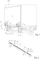
- a tailgate lift 10 is configured to be linked to a vehicle 100.
- the vehicle 100 is a truck of less than eight tons in size, preferably between 3.5 and 5 tons in size.
- the tailgate 10 comprises a loading platform P configured to receive the goods to be loaded or unloaded onto/from the vehicle 100.
- the tailgate 10 comprises two support members 11 ( fig. 2 ) configured to be hooked directly, or indirectly, to the tailgate itself and, in addition, configured to support a transverse bar 12.
- the transverse bar 12 acts as a bumper and is therefore configured to absorb the energy that is generated during a possible impact. Moreover, as will become clearer from the following detailed description, the transverse bar 12 also performs a structural function for the tailgate 10.
- connection means 13 which connect it to a chassis 101 of the vehicle 100 by means of any known fastening member.
- connection means 13 include suitable mechanical connection members, such as brackets, plates, crossbeams, which are fixed to the chassis 101 in any appropriate known manner, typically by bolting.
- connection means 13 comprise a right anchoring bracket 14 and a left anchoring bracket 15, respectively fixed to the right and left side of the vehicle 100.
- the right anchoring bracket 14 and the left anchoring bracket 15 are separate and spaced apart from each other, each being independently connected to the chassis 101. As will become clearer hereinafter, this type of anchoring of the tailgate 10 to the vehicle 100 makes it necessary to be able to vary a center distance I between said support members 11.
- the tailgate 10 also comprises a lifting actuator 16 and a rotation actuator 17, both connected to the connection means 13 at the respective end thereof.
- Both the lifting 16 and rotation 17 actuators are configured as movement means of the platform P and are hydraulic actuators in which the operating fluid is an oil suitable for industrial uses.
- the lifting actuator 16 is disposed on the left side of the vehicle 100, and is thus connected to the left connection member 15, while the rotation actuator 17 is disposed on the right side of the vehicle 100, and is thus connected to the right connection member 14.
- the tailgate 10 Compared to the solutions known in the art, which comprise two pairs of actuators, one on the right and one on the left, each comprising both a lifting actuator and a rotation actuator, the tailgate 10 according to the present invention comprises only two actuators, making it cheaper and lighter than the known solutions.
- the tailgate 10 also comprises a compensation actuator 33, which is in fluid communication with both the lifting actuator 16 and the rotation actuator 17 to control the tilting movement towards the ground of the platform P in its terminal ground connection stroke.
- the compensation actuator 33 is disposed on the left side of the vehicle 100, linked to the lifting actuator 16.
- the tailgate 10 comprises a pair of arms 18, arranged with one on the right side and the other on the left side of the vehicle 100 ( fig. 1 ).
- the support members 11 are each connected to a respective arm of the pair of arms 18, in a manner that will be explained in greater detail below.
- Each arm 18 is pivoted on the connection means 13 at a first end thereof.
- the arm 18 disposed on the right side is pivoted on the right anchoring bracket 14, while the arm 18 disposed on the left side is pivoted on the left anchoring bracket 15.
- the platform P is pivoted on the pair of arms 18, at their respective second ends, opposite said first ends.
- the lifting actuator 16 is connected on one side to said left anchoring bracket 15 and, on the other side, to said arm 18, while the rotation actuator 17 is connected on one side to said right anchoring bracket 14 and on the other side to said platform P.
- the transverse bar 12 Since the connection of the platform P to the chassis 101 of the vehicle 100 takes place through the pair of arms 18 at the two different anchoring brackets 14 and 15, right and left, different and not connected to each other, and since only a lifting actuator 16 and a rotation actuator 17 are provided, arranged one on the right side and one on the left side of the vehicle, it is evident that the transverse bar 12 has a structural function of homogeneously transmitting the movement determined by the lifting actuator 16 between the two sides, right and left, of the vehicle 100. In this way the transverse bar 12 allows the torque that is generated to be transmitted from one side to the other of the vehicle 100, to avoid unwanted inclinations between the right side and the left side of the platform P.
- Each support member 11 is configured as a bracket comprising a first hooking portion 19 and a second hooking portion 20 ( fig. 2 ), configured to be connected to each arm 18 at two different points. This conformation of the support member 11 allows a stable anchoring of the transverse bar 12 to the tailgate 10, in particular to the pair of arms 18, adapted to transmit torque from the right side to the left side of the tailgate.
- one of the two hooking portions 19, 20 of one of the two support members 11 is hooked to the respective point of the arm 18 by means of an adjustment mechanism that allows one support member 11 to be offset angularly with respect to the other, for example by a few degrees or even more.
- the presence of the adjustment mechanism makes it possible to adjust the magnitude of the torque that is transmitted by the transverse bar 12 between the right side and the left side of the vehicle 100.
- Each support member 11 may comprise one or more connection elements 32, such as holes, slots or recesses suitable for connecting in corresponding coupled elements, for example pins, screws, plugs or protrusions, provided on each of the arms 18.
- Each support member 11 also comprises a support portion 21 configured to cooperate with hooking means 22 suitable for hooking the transverse bar 12 to the support member 11.
- the support portion 21 has a shape that is conjugate with a portion of the external surface of the protection member 12 and comprises at least one plate 23 ( fig. 4 ).
- the protection member 12 is elongated and extends along a longitudinal extension axis A ( fig. 3 ).
- the device 10 comprises two support members 11, spaced apart from one another by a center distance I ( fig. 3 ), measured parallel to the longitudinal extension axis A.
- the center distance I is variable as a function of the center distance of the chassis 101 of the vehicle 100.
- the transverse bar 12 is preferably made of a metal material such as aluminum, or steel, and is obtained for example by means of an extrusion process.
- At least one groove 26 is formed on the transverse bar 12 and extends parallel to the longitudinal axis A, preferably along its entire length L.
- the groove 26 is configured to receive the aforementioned hooking means 22.
- the groove 26 is also configured to allow the sliding of said hooking means 22, and therefore of said support members 11, along the longitudinal axis A.
- Said groove 26 comprises both a surface portion 27, fitting with the external surface of the transverse bar 12, having a first width W1, and an internal portion 29, below and communicating with the surface portion 27, and having a second width W2 greater than the first width W1.
- the hooking means 22 comprise at least one screw 30 and a block 31 inserted in the groove 26, in particular in its internal portion 29. This internal portion 29 is configured to receive a respective block 31, which is therefore suitably sized to be received in the internal portion 29.
- the plate 23 and the block 31 are provided with respective holes, not shown, crossed by the screw 30.
- the block hole 31 is threaded to allow the correct clamping of the screw 30.
- two grooves 26 having a substantially equal cross-section, and angled with respect to each other by an angle ⁇ greater than 90°, for example corresponding to about 120°, are formed on the transverse bar 12.
- the plate 23 is shaped so as to at least partially surround the transverse bar 12 so as to overlap said two grooves 26.
- the hooking means 22 comprise at least eight screws 30, at least four of which are linked with one of the two support members 11 and at least four of which are linked with the other support member 11.
- the device 10 of the present invention is particularly advantageous as it allows the assembly times of the tailgate 10 to be greatly reduced.
- the tailgate 10, or at least its part comprising the support members 11 and the transverse bar 12 can be stored in a warehouse already pre-assembled, with the screws 30 loosened with respect to the respective blocks 31, which are already arranged inside the internal portions 29.
- tailgate 10 can be adapted each time to any type of vehicle 100 easily and quickly. This means that it is sufficient to store in the warehouse a single tailgate 10 in accordance with the present invention, which is suitable for being linked to a plurality of commercial vehicle models, without the need to purchase and maintain a plurality of tailgates, for example one or more for each different commercial vehicle model.
- the present invention By means of the present invention, it is therefore possible to store a desired number of tailgates 10, without knowing in advance the vehicle model on which they will be installed, since the support members 11 can advantageously be placed at different center distances I directly at the time of installation. It is clear that this is very advantageous both because it allows the workshops for setting up the vehicles to reduce the value of the material held in stock in the warehouse, and to reduce the volume of the warehouses required. In addition, in the event that these workshops are located far away, even in countries or continents other than those in which the manufacturer of the tailgate is located, the present invention also allows avoiding waiting for the delivery time of the particular piece; time that can sometimes be as long as several weeks.
Landscapes
- Engineering & Computer Science (AREA)
- Mechanical Engineering (AREA)
- Transportation (AREA)
- Vehicle Step Arrangements And Article Storage (AREA)
Applications Claiming Priority (1)
| Application Number | Priority Date | Filing Date | Title |
|---|---|---|---|
| IT102022000018945A IT202200018945A1 (it) | 2022-09-15 | 2022-09-15 | Sponda montacarichi per veicoli |
Publications (1)
| Publication Number | Publication Date |
|---|---|
| EP4339037A1 true EP4339037A1 (de) | 2024-03-20 |
Family
ID=84362746
Family Applications (1)
| Application Number | Title | Priority Date | Filing Date |
|---|---|---|---|
| EP23197610.1A Pending EP4339037A1 (de) | 2022-09-15 | 2023-09-15 | Hubladebühne für fahrzeuge |
Country Status (2)
| Country | Link |
|---|---|
| EP (1) | EP4339037A1 (de) |
| IT (1) | IT202200018945A1 (de) |
Citations (6)
| Publication number | Priority date | Publication date | Assignee | Title |
|---|---|---|---|---|
| US3666121A (en) * | 1970-05-28 | 1972-05-30 | Overhead Door Corp | Trailer hitch |
| SE456733B (sv) * | 1987-03-10 | 1988-10-31 | Z Lyften Prod Ab | Underkoerningsskydd foer lastfordon med bakgavelhissar |
| US6082958A (en) * | 1996-05-21 | 2000-07-04 | Sorensen Hydraulik, Zweigniederlassung, Ulfborg, Filial Af Sorensen Hydraulik Gmbh, Tyskland | Lift-type loading platform system |
| EP1541412A1 (de) * | 2003-12-09 | 2005-06-15 | Sörensen Hydraulik Zweigniederlassung, Ulfborg, Filial af Sörensen Hydraulik GmbH, Tyskland | Ladebordwandsystem |
| EP1627771A1 (de) * | 2004-08-19 | 2006-02-22 | Gerd Bär | Hubladebühne mit querverschiebbarem Verbindungsrohr |
| EP4046866A1 (de) * | 2021-02-19 | 2022-08-24 | Sörensen Hydraulik GmbH | Ladebordwandsystem mit beweglichem unterfahrschutz |
-
2022
- 2022-09-15 IT IT102022000018945A patent/IT202200018945A1/it unknown
-
2023
- 2023-09-15 EP EP23197610.1A patent/EP4339037A1/de active Pending
Patent Citations (6)
| Publication number | Priority date | Publication date | Assignee | Title |
|---|---|---|---|---|
| US3666121A (en) * | 1970-05-28 | 1972-05-30 | Overhead Door Corp | Trailer hitch |
| SE456733B (sv) * | 1987-03-10 | 1988-10-31 | Z Lyften Prod Ab | Underkoerningsskydd foer lastfordon med bakgavelhissar |
| US6082958A (en) * | 1996-05-21 | 2000-07-04 | Sorensen Hydraulik, Zweigniederlassung, Ulfborg, Filial Af Sorensen Hydraulik Gmbh, Tyskland | Lift-type loading platform system |
| EP1541412A1 (de) * | 2003-12-09 | 2005-06-15 | Sörensen Hydraulik Zweigniederlassung, Ulfborg, Filial af Sörensen Hydraulik GmbH, Tyskland | Ladebordwandsystem |
| EP1627771A1 (de) * | 2004-08-19 | 2006-02-22 | Gerd Bär | Hubladebühne mit querverschiebbarem Verbindungsrohr |
| EP4046866A1 (de) * | 2021-02-19 | 2022-08-24 | Sörensen Hydraulik GmbH | Ladebordwandsystem mit beweglichem unterfahrschutz |
Also Published As
| Publication number | Publication date |
|---|---|
| IT202200018945A1 (it) | 2024-03-15 |
Similar Documents
| Publication | Publication Date | Title |
|---|---|---|
| US10683046B2 (en) | Tandem lift auxiliary axle assembly | |
| JP2003505313A (ja) | コンテナハンドリング装置又は台枠 | |
| US20040156706A1 (en) | Wheel-lift assembly for wreckers | |
| US5513901A (en) | Hoist mechanism | |
| US20210283963A1 (en) | Trailer-mountable support assembly for trailer collapse prevention | |
| EP4339037A1 (de) | Hubladebühne für fahrzeuge | |
| US2979214A (en) | Power actuated end gate elevator for motor vehicles | |
| EP4263416B1 (de) | Hubsystem für fahrzeuge | |
| US5263357A (en) | Haulable device for rectifying the shape of a misshapen unibody frame | |
| US9381846B2 (en) | Haul bodies and related apparatus | |
| ZA200303363B (en) | Two sided system for loading trucks. | |
| US20090236897A1 (en) | Vehicle having loading and unloading capabilities | |
| US12479528B1 (en) | Apparatuses and methods for a trailer and elevating trailer bed | |
| US6325579B1 (en) | Lift assist mechanism for railroad car deck | |
| EP0368853A1 (de) | System zum andocken von lastwagen | |
| EP1714828B1 (de) | Kippeinrichtung für einen Lastkraftwagen | |
| CN217201885U (zh) | 一种剪叉式升降作业平台 | |
| US10759323B1 (en) | Dovetail actuating mechanism | |
| US11142111B2 (en) | Hoist apparatus securement system and method | |
| CN210103381U (zh) | 一种卸货升降台 | |
| US20100038881A1 (en) | Mounting Apparatus | |
| KR20230007821A (ko) | 상하차용 램프 | |
| EP4678588A1 (de) | Mehrzweckquerträger zum heben eines fahrzeugs, hebesystem damit und verfahren zum heben eines fahrzeugs | |
| RU2772762C1 (ru) | Средство крепления многооборотное для перевозки автомобильных полуприцепов на вагонах-платформах | |
| SU1044573A1 (ru) | Передвижной разгрузчик бортовых автомобилей и прицепов |
Legal Events
| Date | Code | Title | Description |
|---|---|---|---|
| PUAI | Public reference made under article 153(3) epc to a published international application that has entered the european phase |
Free format text: ORIGINAL CODE: 0009012 |
|
| STAA | Information on the status of an ep patent application or granted ep patent |
Free format text: STATUS: THE APPLICATION HAS BEEN PUBLISHED |
|
| AK | Designated contracting states |
Kind code of ref document: A1 Designated state(s): AL AT BE BG CH CY CZ DE DK EE ES FI FR GB GR HR HU IE IS IT LI LT LU LV MC ME MK MT NL NO PL PT RO RS SE SI SK SM TR |
|
| TPAC | Observations filed by third parties |
Free format text: ORIGINAL CODE: EPIDOSNTIPA |
|
| STAA | Information on the status of an ep patent application or granted ep patent |
Free format text: STATUS: REQUEST FOR EXAMINATION WAS MADE |
|
| 17P | Request for examination filed |
Effective date: 20240919 |
|
| RBV | Designated contracting states (corrected) |
Designated state(s): AL AT BE BG CH CY CZ DE DK EE ES FI FR GB GR HR HU IE IS IT LI LT LU LV MC ME MK MT NL NO PL PT RO RS SE SI SK SM TR |
|
| STAA | Information on the status of an ep patent application or granted ep patent |
Free format text: STATUS: EXAMINATION IS IN PROGRESS |
|
| 17Q | First examination report despatched |
Effective date: 20241023 |