EP4339021A1 - Vorrichtung zum sichern von lasten, insbesondere futterballen, auf einem lastentransportfahrzeug, und lastentransportfahrzeug mit mindestens einer solchen vorrichtung - Google Patents
Vorrichtung zum sichern von lasten, insbesondere futterballen, auf einem lastentransportfahrzeug, und lastentransportfahrzeug mit mindestens einer solchen vorrichtung Download PDFInfo
- Publication number
- EP4339021A1 EP4339021A1 EP23196717.5A EP23196717A EP4339021A1 EP 4339021 A1 EP4339021 A1 EP 4339021A1 EP 23196717 A EP23196717 A EP 23196717A EP 4339021 A1 EP4339021 A1 EP 4339021A1
- Authority
- EP
- European Patent Office
- Prior art keywords
- upright
- vehicle
- platform
- support
- loads
- Prior art date
- Legal status (The legal status is an assumption and is not a legal conclusion. Google has not performed a legal analysis and makes no representation as to the accuracy of the status listed.)
- Pending
Links
Images


Classifications
-
- B—PERFORMING OPERATIONS; TRANSPORTING
- B60—VEHICLES IN GENERAL
- B60P—VEHICLES ADAPTED FOR LOAD TRANSPORTATION OR TO TRANSPORT, TO CARRY, OR TO COMPRISE SPECIAL LOADS OR OBJECTS
- B60P7/00—Securing or covering of load on vehicles
- B60P7/06—Securing of load
- B60P7/135—Securing or supporting by load bracing means
- B60P7/15—Securing or supporting by load bracing means the load bracing means comprising a movable bar
-
- B—PERFORMING OPERATIONS; TRANSPORTING
- B60—VEHICLES IN GENERAL
- B60P—VEHICLES ADAPTED FOR LOAD TRANSPORTATION OR TO TRANSPORT, TO CARRY, OR TO COMPRISE SPECIAL LOADS OR OBJECTS
- B60P7/00—Securing or covering of load on vehicles
- B60P7/06—Securing of load
- B60P7/08—Securing to the vehicle floor or sides
- B60P7/12—Securing to the vehicle floor or sides the load being tree-trunks, beams, drums, tubes, or the like
-
- B—PERFORMING OPERATIONS; TRANSPORTING
- B60—VEHICLES IN GENERAL
- B60P—VEHICLES ADAPTED FOR LOAD TRANSPORTATION OR TO TRANSPORT, TO CARRY, OR TO COMPRISE SPECIAL LOADS OR OBJECTS
- B60P7/00—Securing or covering of load on vehicles
- B60P7/06—Securing of load
- B60P7/135—Securing or supporting by load bracing means
-
- B—PERFORMING OPERATIONS; TRANSPORTING
- B62—LAND VEHICLES FOR TRAVELLING OTHERWISE THAN ON RAILS
- B62D—MOTOR VEHICLES; TRAILERS
- B62D33/00—Superstructures for load-carrying vehicles
- B62D33/02—Platforms; Open load compartments
- B62D33/023—Sideboard or tailgate structures
- B62D33/027—Sideboard or tailgate structures movable
Definitions
- the technical field of the invention is that of the road transport of loads, such as large bales of fodder (straw, hay, silage, hemp, etc.), and more generally any large merchandise (for example, rolls of cables or pipes or cylindrical bales of paper or other material) capable of being transported on a transport vehicle, and in particular a road trailer type vehicle.
- loads such as large bales of fodder (straw, hay, silage, hemp, etc.)
- any large merchandise for example, rolls of cables or pipes or cylindrical bales of paper or other material
- the invention relates to the securing and maintaining of these loads on a load transport vehicle.
- Such a side barrier system is, for example, described in the French patent FR3081284 B1 , which describes a platform comprising at least two barriers, in the form of rigid bars, mounted on the chassis and capable of blocking the loads by wedging the loads between them.
- these side barrier systems are rigid and generally metallic structures. As a result, these systems do not conform to the lateral shape of the loads and therefore do not allow optimal support of them. In addition, these rigid systems are likely to damage loads. Furthermore, such systems can generate noise, particularly during empty transport or when transporting metal loads.
- each lateral structure comprising a pair of end posts and a plurality of cables coupled to and extending between these posts.
- the cables are kept under tension between the uprights using conventional tensioners.
- the present invention aims to remedy these drawbacks by proposing a load securing device on a load transport vehicle which allows permanent and reliable lateral retention of loads, which does not risk damaging the loads, which is adjustable in length to adapt to various load dimensions, and which is easy and quick to install.
- the present invention also proposes a load transport vehicle equipped with at least one such load securing device, which vehicle is then versatile, able to adapt to different loading heights, easy loading and unloading, and easy and quick to use.
- the subject of the present invention is a device for securing loads, in particular bales of fodder, on a load transport vehicle, which securing device comprises at least one flexible elongated element whose two longitudinal ends are coupled to a pair of parallel vertical uprights, the uprights being spaced from one another such that the or each flexible elongated element extends horizontally between said uprights, at least one of the longitudinal ends of the or each flexible elongated element being coupled to the respective upright via a connection assembly, which connection assembly is integral with said longitudinal end and cooperates with said upright, characterized in that the or each connection assembly is mounted movable in translation relative to the upright via a slide connection in a direction orthogonal to a longitudinal axis of the upright and parallel to the plane comprising the pair of uprights.
- Such a slide connection allows the distance between the connection assembly and the upright to vary while preventing rotation of the connection assembly relative to the upright.
- the slide connection allows the connection assembly to slide relative to the upright.
- the flexible elongated element has the advantage of easily adapting to the shape of the load(s) and of following its contour, unlike a rigid element. Such a flexible element therefore allows better load retention. In addition, such a flexible element makes it possible to avoid the noise which could be generated during empty transport with a rigid metal element. Finally, such a flexible element is of reduced cost.
- connection assembly is provided at each of the two longitudinal ends of the or each flexible elongated element.
- a tensioning member is arranged between the or at least one of the connection assemblies and the corresponding upright so as to tend to bring the corresponding longitudinal end of the element closer together. slender flexible upright.
- the tensioning member is an elastic biasing member, such as in particular a compression spring, a tension spring, a rotating spring or a hydraulic cylinder, acting on the connection assembly so as to stress the connection assembly towards a minimum extension of the connection assembly between the longitudinal end of the elongated element and the upright.
- an elastic biasing member such as in particular a compression spring, a tension spring, a rotating spring or a hydraulic cylinder
- Such a tensioning member allows the flexible elongated element to be permanently tensioned, at the maximum permitted tension, and automatically. Therefore, in use, this allows the flexible elongated element to come to bear on the load, for optimal blocking.
- the use of a compression spring makes it possible to apply a constant tension force to the connection assembly and therefore to the flexible elongated element.
- the or each connection assembly comprises a movable member forming a slide and an adjustment member integral with the movable member and cooperating with the corresponding upright so as to limit the translational movement of the connection assembly relative to the upright, the slide connection comprising through orifices forming a slide provided along the corresponding upright and arranged so as to slideably receive the movable member and the adjustment member.
- each upright comprises a plurality of through holes spaced along the longitudinal direction of the upright, so as to allow the positioning of the or each connection assembly at different heights.
- the device is easily adaptable to the height of the load to be transported.
- two consecutive similar through orifices namely two orifices intended to receive the same part of the connection assembly, are spaced at a constant pitch of 150 mm.
- the adjustment member is a screw-nut assembly comprising a screw passing through the upright along an axis parallel to the direction of translation, and a nut screwed onto the screw, the upright being interposed between a head of the screw and the nut, one or the other of the head of the screw and the nut being integral with the movable member.
- the tensioning member is a spring, for example compression
- the spring is crossed by the screw and is connected on the one hand to the upright and on the other hand to the adjustment member.
- Such a screw-nut assembly makes it possible to retain the movable member in the orifices of the upright while allowing rapid and easy adjustment of the extension stroke of the slide connection, therefore easy and rapid adjustment of the length of the element slender, supple.
- the head of the screw and the nut constitute simple stop means.
- such a screw-nut assembly can be easily dismantled and reassembled, in particular using a wrench, thus making it possible to separate the connecting assembly from the upright in order to reposition it in another desired position on the upright.
- the movable member is a U-shaped part comprising two guide fingers, parallel to each other and oriented in the direction of translation, the two fingers being interconnected by an axis parallel to the longitudinal axis of the upright and to which is connected the corresponding longitudinal end of the flexible elongated element.
- the longitudinal end of the flexible elongated element is connected to the movable member via a loop formed at said end, which loop is mounted around the axis, the axis being in the shape of a bolt and being taken in eyelets formed on each guide finger.
- a connection arrangement between the flexible elongated element and the movable member allows practical and easy assembly and disassembly of said flexible elongated element. Consequently, the flexible element can be easily replaced by another flexible element, in particular to adapt to the dimensions of the loads to be secured.
- the or each flexible elongated element is advantageously a strap.
- Such a strap has the advantages of being inexpensive and not damaging the loads when the strap comes into close contact against the loads.
- the or each flexible elongated element could be a cable, a rope or the like.
- the securing device comprises a plurality of flexible elongated elements, preferably two flexible elongated elements, spaced vertically from each other.
- the vertical spacing between the two elements can be chosen such that, in use, the lower element is able to come into position. bearing against a stage of stacked loads and the upper element is able to come to bear against another stage of stacked loads.
- the present invention also relates to a vehicle for transporting loads, in particular bales of fodder, the vehicle comprising a loading platform having a front end, a rear end and two lateral sides extending between the front and rear ends , the vehicle being characterized by the fact that it comprises at least one load securing device as defined above, preferably two securing devices, the or each securing device extending along a respective lateral side of the loading platform, each upright being connected to the loading platform via a respective pivoting assembly, such that the or each of the devices is mounted movable with respect to the loading platform enters a loading position, in which the device is positioned below the platform, and at least one transport position, in which the device is positioned above the platform.
- Such a vehicle according to the invention allows lateral securing of loads on the loading platform, for secure transport thereof.
- tie-downs In use, in the transport position, tie-downs help retain loads on the loading platform and prevent loads from moving sideways and falling out of the vehicle. In the loading position, the tie-down devices provide access to the loading platform and facilitate the loading of loads onto the loading platform or their unloading.
- the securing device comprises, for the or each flexible elongated element, a tensioning member
- this makes it possible to prevent said flexible elongated element from relaxing during its movement from its loading position to its position transport and arrives twisted against the loads.
- poor lateral securing, if necessary poor lateral strapping, and premature wear of the flexible elongated element are avoided.
- each upright is capable of being detachably connected to the respective pivoting assembly at either end of the upright, if necessary.
- Such a removable assembly makes it possible to change the direction of assembly of the upright, the upper end of the upright being able to become the lower end of the upright after turning it over.
- the reversal of the two amounts of the same pair of uprights thus makes it possible, without the need to move the flexible elongated element(s) along the uprights, to increase the possibilities of positioning the flexible elongated elements in height.
- the uprights could be placed in a first configuration for the transport of bales of fodder arranged in three rows, first configuration in which the uprights are oriented in such a way that the elongated elements flexible are supported against the two upper rows.
- first configuration in which the uprights are oriented in such a way that the elongated elements flexible are supported against the two upper rows.
- the transport vehicle is a non-self-propelled vehicle on wheels, of the trailer type, intended to be towed by a tractor vehicle.
- each pivoting assembly comprises a pair of parallel arms, of the same length and each having first and second ends articulated respectively to a support secured to one end of the loading platform and to the corresponding upright so as to form with the upright a deformable parallelogram, each pivoting assembly further comprising a cylinder articulated between the support and one of the arms, such that a retraction or extension of the cylinder causes the pair of arms to pivot around their first ends and the movement of the upright between the loading and transport positions, the cylinders associated with the uprights of the same securing device being synchronized, two pivoting assemblies arranged at the same end of the platform being connected to the same support.
- Each pivot assembly having its own actuator the two pivot assemblies connected to the pair of posts of one of the tie-down devices can be moved independently of the two pivot assemblies connected to the pair of posts of the other tie-down device.
- the two tie-down devices can be placed in the same position or one of the tie-down devices can be placed in the loading position while the other tie-down device is placed in the transport position.
- such assemblies being actuated by cylinders, the passage of the securing devices from one position to another is easy and rapid and can be repeated many times without requiring any effort on the part of a user.
- each support is mounted movable in height relative to the loading platform via an elevator assembly, which elevator assembly comprises a vertical actuator, in particular a vertical cylinder, mounted between the loading platform.
- elevator assembly comprises a vertical actuator, in particular a vertical cylinder, mounted between the loading platform.
- loading and support a pair of vertical guide rails attached to the corresponding end of the platform and a mounted trolley movable in vertical translation along the rails, the support being integral with the carriage, such that a movement of the actuator causes a movement in vertical translation of the support relative to the platform between a low position and a high position , the vertical actuators associated with each of the two supports being synchronized.
- the carriage comprises a pair of movable crosspieces arranged one above the other, each crosspiece carrying a caster at each of its two ends capable of being received and guided in a corresponding rail, one of the crosspieces being secured to the upper end of the support and the other crosspiece being secured to the lower end of the support.
- each support could be mounted fixed relative to the platform.
- the advantage of a mobile support compared to a fixed support is to allow better height adjustment of the position of the tie-down devices in order to better adapt to load heights of different heights.
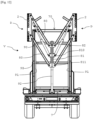
- the load transport vehicle V C is particularly suitable for transporting bales of fodder, bales of fodder being represented in dotted lines on the Figure 2 .
- substantially round bales of fodder are stacked to a certain height, in three superimposed rows.
- the securing devices D of loads C carried by the vehicle V are arranged so as to come into contact with the bales of forage on each side of the vehicle V, in particular with the bales of the two upper rows, in order to avoid transverse movement bales of fodder and their fall out of the vehicle V.
- vehicle V is not limited to the application shown nor to the agricultural industry, but that it could be used for the transport of any loads C stacked on the vehicle V.
- the vehicle V comprises at least one securing device D for loads C.
- the vehicle V comprises two securing devices D positioned on each side of the vehicle V.
- the vehicle V could include a single tie-down device D positioned on one of the two sides of the vehicle V.
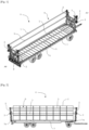
- the or each securing device D for loads C comprises at least one flexible elongated element 1, a pair of vertical uprights 2, at least one connection assembly 3 for the or each flexible longitudinal element 1, and preferably , at least one tensioning member 4 for the or each flexible longitudinal element 1.
- the or each securing device D comprises at least one flexible elongated element 1, preferably two flexible elongated elements 1.
- the number of flexible elongated elements 1 is not limited to one or two, and could be greater than two.
- the or each flexible elongated element 1 is intended to come into contact with loads C to be transported in order to hold them in place.
- the or each flexible elongated element 1 is intended to allow lateral support of the loads C.
- each flexible elongated element 1 is a strap.
- This strap 1 comprises a strip of fabric having two opposite faces of which a face intended to come to bear against the loads C and a face intended to be directed away from the loads C.
- the strap 1 has two longitudinal ends 10.
- each longitudinal end region is folded in the form of a loop , which loop is capable of being connected to a connection assembly 3.
- Each strap 1 has a width, a thickness and a length which are chosen according to the dimensions of the loads C to be maintained. Strap 1 can be made of nylon type fabric.
- each flexible elongated element 1 is designated by the term “strap”.
- the flexible elongated element 1 is not limited to a strap and could also be a rope, a cable or any other strip of flexible material.
- the straps 1 extend parallel to each other, one above the other with a certain spacing between the straps 1.
- These straps 1 extend between the two vertical uprights 2 , in the plane comprising the two uprights 2. In other words, the straps 1 extend in a horizontal direction, perpendicular to the vertical direction of the uprights 2.
- the pair of uprights 2 thus have the function of supporting the straps 1 and maintaining them in their horizontal extended position.
- each upright 2 has a longitudinal axis, a lower end and a upper end.
- Each upright is made in the form of a tubular metal profile of rectangular section having two small opposite faces 20 and two large opposite faces 21. One of the large faces 21 is directed towards the strap 1.
- the low and high ends are open ends which are each closed by a cap 22.
- Each upright 2 has through holes 23, 24 which open onto each of the large faces 21. These through holes 23, 24 are configured to receive the connection assembly 3 with clearance allowing the connection assembly 3 to slide relative to each other. to amount 2.
- each upright 2 comprises a plurality of series of orifices 23, 24.
- Each series of orifices 23, 24 comprises two orifices of rectangular or square section 23 and one orifice of circular section 24 interposed between the two orifices of rectangular or square section 23.
- each upright 2 has five orifices of circular section 24 and seven orifices of square section 23. This represents five possible positions for the connection assembly 3 and therefore five possibilities for height adjustment.
- each orifice of rectangular or square section 23 is positioned one above the other and spaced from one another.
- the series of orifices 23, 24 are regularly distributed along the upright 2, between the high and low ends of the upright 2.
- each orifice of circular section 24 is defined by a cylindrical tubular sleeve which extends from a large face 21 to the other of the amount 2 and which projects beyond the large face 21 opposite the strap 1.
- each orifice of square or rectangular section 23 can be defined by a tube of square or rectangular section which extends through the upright 2, from one large face 21 to the other, and projects slightly on either side of said faces 21 of the upright 2.
- each upright 2 can have a length of 1.185 meters, a distance between two large faces 21 of 8 cm and a distance between two small faces 20 of 18 cm.
- Each cylindrical tubular sleeve 24 can have a length of 12.5 cm, i.e. a projecting length of 4.5 cm, and a diameter of 76.1 mm.
- Each square section tube 23 can have a length of 10 cm, i.e. a projecting length of 1 cm on either side of the upright 2, and a square section of 60 mm by 60 mm.
- these two straps 1 are spaced from each other by 60 cm.
- the distance between the two uprights 2 of the same pair of uprights 2 can be approximately 11.6 meters and the width of each strap 1 can be 12.5 cm.
- connection assembly 3 is provided at each longitudinal end 10 of each strap 1 and makes it possible to connect each of said ends 10 to the corresponding upright 2.
- each connection assembly 3 and the corresponding upright 2 are configured to obtain a slide connection between the connection assembly 3 and the upright 2.
- Such a slide connection makes it possible to guide the connection assembly 3 in translation relative to the upright 2, and therefore to move the strap 1 relative to the upright 2 in the direction of the length of the strap 1.
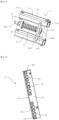
- connection assembly 3 comprises a movable member 5 forming a slide and an adjustment member 6.
- the movable member 5 forming a slide is in the form of a U-shaped part.
- a base links two branches oriented at 90 degrees relative to this base.
- the base of the U is an axis 50 positioned parallel to the longitudinal axis of the upright 2.
- the axis 50 can be in the form of a bolt whose rod passes through the opposite ends of each branch. This rod is dimensioned so as to be received in the loop formed at the longitudinal end 10 of the strap 1. In other words, the length of the rod extending between the two branches is substantially equal to the width of the strap 1.
- the axis 50 can be in the form of a central rod mounted in a socket and held in place by radial pins.
- the socket extends between the two branches and the stem, is of length greater than the length of the socket, and projects from either side of the branches.
- Such an axis 50 is also easily separable with respect to the branches.
- the branches of the U are formed by guide fingers 51.
- Each guide finger 51 has one end connected to the axis 50 and an opposite free end. The end connected to the axis 50 has an eyelet for the passage of the rod of the axis 50.
- the two guide fingers 51 are parallel to each other and perpendicular to the longitudinal axis of the upright 2.
- the plane comprising the part U-shaped is perpendicular to the large faces 21 of the upright 2.
- Each guide finger 51 has a square or rectangular section dimensioned such that the guide finger 51 is able to slide inside the orifice of square or rectangular section 23 corresponding to the amount 2.
- Each finger 51 can be in the form of a tube with a square or rectangular section whose open end on the strap side 1 is closed by a plug 510.
- the movable member 5 is mounted relative to the amount 2 such that the axis 50 is located in the space formed between the two uprights 2 and that the free end of each guide finger 51 can project beyond the face of the upright 2 opposite the side face strap 1.
- the movable member 5 is mounted movable in translation relative to the upright 2 in a direction of translation which is parallel to the plane comprising the two uprights 2.
- a bolt 511 can be provided at the free end of one of the two guide fingers 51. This bolt 511 passes through the finger 51 parallel to the longitudinal axis of the upright 2.
- the nut and the head of the bolt 511 project from either side of the guide finger 51 and are not able to be received in the orifice 23 of the upright 2 receiving the guide finger 51.
- this bolt 511 serves as a safety stop, preventing the movable member 5 from separating from the upright 2 during a translation of the movable member 5 in the direction of the opposite upright 2.
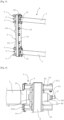
- the adjustment member 6 is a screw-nut assembly. This adjustment member 6 has the function of defining and limiting the travel of translational movement of the movable member 5 relative to the upright 2.
- the adjustment member 6 comprises a screw 60 secured to the movable member 5 and a nut 61 mounted movable relative to the screw 60. More precisely, the screw 60 has a head 600 and a rod 601.
- the head 600 is integral with a spacer 62 connecting the two guide fingers 51 together.
- the spacer 62 comprises a plate 620 and an insert 621 formed in one piece, the insert 621 being integral with the face of the plate 620 on the strap side 1.
- the rod 601 passes through a central orifice made in the plate 620 so that the head 600 is housed in the insert 621.
- the insert 621 has an orifice complementary to the contour of the head 600, in particular a hexagonal orifice. This complementarity makes it possible to prevent the rotation of the screw 60 around the axis of its rod 601.
- the plate 620 extends parallel to the axis 50 and is positioned in the vicinity of the axis 50. Thus, at the mounted state, the spacer 62 extends between the axis 50 and the upright 2.
- the rod 601 is a threaded rod which extends parallel to the guide fingers 51, passes through an orifice of circular section 24 corresponding to the upright 2 and protrudes beyond the face of the upright 2 opposite the strap 1.
- the nut 61 is mounted around the rod 601, in particular, around the region of the rod 601 which projects beyond the upright 2 opposite the strap 1
- the adjustment of the stroke of translational movement of the movable member 5 is carried out by screwing or unscrewing the nut 61 relative to the screw 60. This stroke is limited on the one hand by the spacer 62 and on the other hand on the other hand by the nut 61, which serve as a stop.
- a bell-shaped or cup-shaped element 63 cooperates with the nut 61 and is mounted around the rod 601.
- the concavity of the bell-shaped element 63 is directed towards the strap 1.
- the bell-shaped element 63, as well as the nut 61, are dimensioned such that they are able to be received inside the sleeve of the orifice of circular section 24.
- each strap 1 is connected to each of the two uprights 2 by a connection assembly 3 according to the present invention, a tensioning member 4 is provided at at least one of these connection assemblies 3 In the preferred embodiment shown, for each strap 1, a tensioning member 4 is provided between each of the two connection assemblies 3 and the associated upright 2.
- the tensioning member 4 has the function of tending to bring the longitudinal end 10 of the strap 1 coupled to this connection assembly 3 closer to the corresponding upright 2.
- the tensioning member tensioning member 4 is an elastic biasing member
- such a tensioning member 4 has the function of permanently biasing the longitudinal end 10 of the strap 1 in the direction of the upright 2 to which said end 10 is connected, and therefore of tension the strap 1 permanently and automatically and constantly.
- the tensioning member 4 is a helical compression spring.
- the spring 4 extends along the axis of the rod 601 of the adjustment member 6 between a first end and a second end. More precisely, the spring 4 is mounted around the rod 601. The first end rests on one of the faces of the upright 2. In particular, for greater compactness, the first end rests on a closing wall 25 of the upright 2 located in the plane of the face of the upright 2 strap side 1 ( Figure 6 ). This closing wall 25 closes the end of the sleeve 24 on the strap 1 side and is provided with a central orifice dimensioned to receive the rod 601 of the screw 60.
- the second end rests on the face of the nut 61 directed towards the amount 2, or in the case where the bell-shaped element 63 is present, on the inner face of the bell-shaped element 63.
- the spring 4, the bell-shaped element 63 and the sleeve 24 are dimensioned such that the spring 4, the bell-shaped element 63 and the nut 61 are able to be received inside the sleeve 24.
- spring 4 extends completely inside the sleeve 24.
- the bell-shaped element 63 is located at the open end of the sleeve 24, the spring 4 then being hidden inside the sleeve 24 and the bell-shaped element 63.
- the compression spring 4 is therefore positioned inside the sleeve 24 and between the closing wall 25 of the upright 2 and the bell-shaped element 63.
- the stroke of the compression spring 4 is adjusted to be approximately 60 mm.
- the guide fingers 51 are dimensioned such that when the spring 4 moves over a stroke of 60 mm (extension of the spring), the length of the finger 51 projects beyond the face of the upright. 2 opposite strap 1 is approximately 54 mm.
- the present invention also relates to a vehicle V for transporting loads C equipped with securing devices D for loads C according to the present invention, the or each securing device D being as described above.
- the load transport vehicle V C according to the preferred embodiment of the present invention comprises a loading platform 7, two tie-down devices D and four pivoting assemblies 8.
- Vehicle V represented on the Figures 1, 2 And 7 to 12 is a trailer-type towed vehicle intended to be coupled to a towing vehicle.
- This vehicle V has a chassis extending longitudinally along a longitudinal axis and equipped with a loading platform 7 intended to receive the loads C to be transported.
- vehicle V could also be any other towed vehicle, as well as a towing vehicle, for example of the truck type equipped with a loading platform at the rear of the driver's cabin.
- the terms “upper” or “high” and “lower” or “low” must be understood according to the in-service position of the vehicle V, that is to say the position in which the chassis rests on the ground on which the vehicle V is intended to run.
- the terms “front”, “rear” must therefore be understood according to the position in service of the vehicle V and the direction of advancement of the vehicle V on said ground when the vehicle V advances.
- the loading platform 7 has a front end 7a, a rear end 7b and two side sides 7c extending between the front 7a and rear 7b ends. If we considers the longitudinal direction of the platform 7, the front end 7a corresponds to the front transverse edge AV of the platform 7, the rear end 7b corresponds to the rear transverse edge AR and the lateral sides 7c correspond to the longitudinal edges. Front and rear frames 70 are attached, respectively, to the front 7a and rear 7b ends. The frames 70 extend in a plane perpendicular to the plane of the loading platform 7. Each frame 70 is delimited by a pair of vertical supports 70v connected together by two horizontal supports 70h.
- the two securing devices D are arranged on each side of the platform 7.
- one of the devices D extends along one of the lateral sides 7c of the platform 7 and the another device D extends along the other lateral side 7c of the platform 7.
- the two securing devices D are positioned facing each other on each side of the platform 7. More precisely, each device D has an upright 2 positioned at the rear end 7b of the platform 7 and an upright 2 positioned at the front end 7a of the platform 7, substantially in alignment of the associated longitudinal edge, the straps 1 extending along said longitudinal edge of the platform 7.
- each of the four uprights 2 shown is connected to the loading platform 7 via a pivoting assembly 8.
- the vehicle V shown comprises four pivoting assemblies 8, including two pivoting assemblies 8 at the front end 7a of the loading platform 7 and two pivoting assemblies 8 at the rear end 7b thereof.
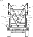
- These pivoting assemblies 8 are configured such that each securing device D is movable relative to the loading platform 7 between a loading position ( Figures 8 and 9 ) and at least one transport position ( Figures 1, 2 , 7 And 10-12 ).
- each upright 2 When moving between these positions, each upright 2 is maintained in a vertical position.
- the two devices D In the transport position(s), the two devices D are positioned above the loading platform 7, at a height allowing the loads C carried by the platform 7 to be blocked laterally.
- the uprights 2 and the straps 1 of at least one of the two devices D are positioned below the loading platform 7 so as to free access to at least one of the sides of the platform 7.
- the fact that the two securing devices D are mounted movable relative to the loading platform 7 makes it possible to choose which device D to move depending on the side by which it is desired to load or unload the platform 7 .
- Each pivoting assembly 8 comprises a pair of arms 80.
- the pair of arms 80 comprises two arms 80 parallel to each other and each having one end articulated to a support 81 and one end articulated to the associated upright 2.
- one of the arms 80 called lower arm, has one end pivotally connected to a lower end region of the associated support 81, around a horizontal axis of rotation and parallel to the longitudinal axis of the platform 7, and one end pivotally connected to the lower end of the upright 2, around an axis of rotation parallel to the axis of rotation of the other end of the arm 80.
- the other arm 80 has one end connected pivotally to the associated support 81, in a high end region of the support 81 positioned above the articulation point of the lower arm 80, around an axis of rotation horizontal and parallel to the longitudinal axis of the plate -form 7, and one end pivotally connected to the upper end of the upright 2, around an axis of rotation parallel to the axis of rotation of the other end of the arm 80.
- the arms 80 upper and lower can be connected to the upper and lower ends, respectively, of the upright 2 or to regions close to said ends.
- the two arms 80, the upright 2 and the support 81 form a deformable parallelogram.
- the axis of rotation between each arm and the upright is configured to be removable such that the upright can be separated from the pair of arms and can be reconnected to the arms after the upright is turned over.
- the platform 7 includes means 82 for automated movement of each pivoting assembly 8 between lowered and raised positions.
- the means 82 for moving the two devices D are independent of each other and the means 82 for moving the same device D are synchronized.
- the movement means 82 comprise a first pair of jacks 82 associated with one of the devices D and a second pair of jacks 82 associated with the other device D.
- Each jack 82 makes it possible to control the rotational movement of the associated deformable parallelogram around its four axes of rotation.
- a first cylinder 82 of the first pair is mounted at the front end 7a so that its body is articulated around an axis of rotation secured to the front support 81 and that its rod is articulated around an axis of rotation secured to the arm 80 upper of the front swivel assembly 8.
- the second cylinder 82 of the first pair is articulated between the rear support 81 and the upper arm 80 of the rear pivoting assembly 8.
- the axis of rotation between the body of the cylinder 82 and the support 81 is integral with a plate 810 fixed to the support 81, substantially at mid-length of the support 81, and projecting from either side of the support 81, transversely to the support 81.
- the axis of rotation is off-center relative to the longitudinal axis of the support 81.
- the cylinders 82 of the second pair are mounted symmetrically with respect to the cylinders 82 of the first pair.
- the extension of the cylinders 82 of the first pair of cylinders, respectively of the second pair of cylinders 82 causes the movement of the associated device D towards a elevated position known as transport.
- the retraction of the jacks 82 of the first pair of jacks 82, respectively of the second pair of jacks 82 causes the associated device D to move towards the lowered so-called loading position.
- the pairs of arms 80 of the two pivoting assemblies 8 located at the rear end 7b are articulated on the same support 81, called rear support.
- the pairs of arms 80 of the two pivoting assemblies 8 located at the front end 7a are articulated on the same support 81, called the front support.
- the axis of rotation between each arm 80 and the associated support 81 is secured to the support 81 via a plate 811 extending in the plane of the pivoting assembly 8 and whose wings project from either side other of the support 81.
- the axes of rotation are off-centered relative to the longitudinal axis of the support 81.
- Each support 81 is in the form of a bracket extending vertically and coupled to the loading platform 7.
- the bracket is, preferably, a hollow tube with a square section.
- each support 81 can have a length of 1.23 meters and a square section of 10 cm by 10 cm.
- Each arm 80 can have a length of 1.6 meters and a square section of 80 cm side.
- each support 81 is mounted fixed relative to the platform 7.
- the front support 81 has a lower end secured to the platform 7 at the level of the center of the front end 7a.
- the rear support 81 has a lower end secured to the platform 7 at the center of the rear end 7b.
- the lower end of each support 81 is made integral with the platform 7 by screwing.
- Each support 81 is also secured to two crosspieces 71 fixedly mounted relative to the associated frame 70. These crosspieces 71 extend parallel to the horizontal supports 70h and are spaced from one another along the vertical supports 70v. These crosspieces 71 are positioned at the level of the plates 811 connecting each arm 80 to the support 81.
- each support 81 is mounted movably relative to the platform 7 via an elevator assembly 9, so that each support 81 can be positioned at a variable height between a low position and a high position.
- the elevator assembly 9 allows height adjustment of the position of the support 81, and therefore of the associated pivoting assemblies 8.
- This embodiment in which each support 81 is movable in a height direction makes it possible to position the straps 1 at a higher height than in the fixed support embodiment.
- Such an assembly forming an elevator 9 therefore makes it possible to offer a more versatile vehicle V and capable of adapting to different load heights C.
- Each elevator assembly 9 comprises a carriage constituted by a pair of crosspieces 90 movably mounted along a corresponding pair of rails 91 secured to the associated frame 70 and a vertical cylinder 92 configured to move the movable crosspieces 90 along the rails 91.
- the pair of crossbars 90 includes an upper crossbar and a lower crossbar.
- Each crosspiece 90 carries, at each of its two ends, a caster 900.
- the casters 900 of the upper crosspiece 90 are directed towards the casters 900 of the lower crosspiece 90.
- the axis of rotation of each caster 900 is parallel to the axis of the crosspieces 90.
- the crosspieces 90 are received in the frame 70 and extend from one vertical support 70v to the other, parallel to the horizontal supports 70h.
- Each vertical support 70v of the frame 70 carries, on its face directed towards the inside of the frame 70, a guide rail 91.
- the two guide rails 91 of the same pair are therefore positioned facing each other .
- Each rail 91 is in the form of a U-shaped profile extending from the lower horizontal support 70h of the frame 70 and to a region adjacent to the upper horizontal support 70h.
- the rails 91 are configured to receive the casters 900 in order to allow the movement of the sleepers 90 to be guided along the rails 91.
- the sleepers 90 are mounted movable relative to the platform 7, in a direction perpendicular to the plane of platform 7.
- the elevator assembly 9 mounted at the rear end 7b of the platform 7 is mounted symmetrically with respect to the elevator assembly 9 mounted at the front end 7a of the platform 7.
- Each support 81 is fixed to the upper crosspiece 90 at the level of the plate 811 to which the upper arm 80 is connected and is fixed to the lower crosspiece 90 at the level of the plate 811 to which the lower arm 80 is connected.
- the vertical cylinder 92 is a hydraulic cylinder.
- the vehicle V includes a vertical cylinder 92 at each front end 7a and rear end 7b.
- the vertical cylinder 92 extends vertically parallel to the longitudinal axis of the support 81 and is included in the longitudinal vertical plane in which the support 81 is located.
- the vertical cylinder 92 is coupled on the one hand to the support 81 and on the other hand to the platform 7.
- the vertical cylinder 92 has a body connected to a lower horizontal axis perpendicular to the axes of rotation of the arms 80 and secured to the transverse edge of the vehicle V, and a rod connected to an upper axis parallel to the lower axis and secured to the support 81, in particular to the plate 811 at the upper end region of the support 81.
- the front and rear vertical cylinders 92 operate synchronously.
- an extension of the vertical cylinders 92 makes it possible to move the supports 81 along a vertical direction in order to vary, in particular to increase, the height at which the supports 81 and therefore the devices D can be positioned.
- the height of a bale of fodder can vary from 1 m to 1.20 m, the travel of each vertical cylinder 92 and therefore of each mobile support 81 must be adjusted to 60 cm in order to adapt to this variation in height.
- the tie-down devices are initially in a high transport position
- the vertical cylinders 92 are retracted in order to to move the movable crosspieces 90 towards their lower position
- the pair of cylinders 82 associated with the pivoting assemblies 8 of one of the securing devices D are retracted in order to position the securing device D in the loading position.
- the driver can then load the loads C onto the platform 7 from the lateral side 7c of the vehicle V, the securing device D of which is in the loading position.
- the pair of jacks 82 associated with the pivoting assemblies 8 of the device D which has been placed in the loading position are extended in order to to move the lashing device D towards a transport position in which the straps 1 come into lateral support against the loads C.
- the loads C are held in place between the two lashing devices D in the transport position and are prevented from moving laterally.
- the vertical cylinders 92 are extended in order to move the movable crosspieces 90 towards the high position.
- each strap 1 can be positioned at an appropriate height between the two uprights 2. To do this, the driver simply has to separate each connection assembly 3 from the associated upright 2 , after unscrewing the nut 61, and raising it to the desired height along the upright 2, in one of the series of holes 23, 24 provided. To unload the loads C, it is then sufficient to return at least one of the securing devices D to the loading position. Once the loads C have been unloaded from the vehicle V, it is preferable to place the two securing devices D in the loading position. This makes it possible to limit the wear of the various moving parts of the vehicle V and also to limit the total height of the vehicle V.
- the vehicle V according to this second embodiment allows you to transport both bales of wet hay and larger bales of straw, without having to change vehicles V.
- the load transport vehicle V C according to this second embodiment of the invention has the advantage of adapting to more loads, namely loads C of different heights.
- the vehicle V for transporting loads C also makes it possible to adapt to loads C of different heights.
- the height position of the straps 1 by modifying the position of each strap 1 along the uprights 2 thanks to the plurality of series of orifices 23, 24, it is possible to adjust the height position of the straps 1 without the need to move the straps 1 along the uprights 2.
- simply dismantle the pair of removable uprights 2 turn over the uprights 2 and connect them again to the pivoting assemblies 8 respective.
- a strap 1 is at the upper end of the upright 2 before turning, it will be at the lower end of the upright 2 after turning and will therefore be positioned at a different height.
Landscapes
- Engineering & Computer Science (AREA)
- Transportation (AREA)
- Mechanical Engineering (AREA)
- Chemical & Material Sciences (AREA)
- Combustion & Propulsion (AREA)
- Fittings On The Vehicle Exterior For Carrying Loads, And Devices For Holding Or Mounting Articles (AREA)
Applications Claiming Priority (1)
| Application Number | Priority Date | Filing Date | Title |
|---|---|---|---|
| FR2209188A FR3139519A1 (fr) | 2022-09-13 | 2022-09-13 | Dispositif d’arrimage de charges, notamment de balles de fourrage, sur un véhicule de transport de charges, et véhicule de transport de charges comprenant au moins un tel dispositif d’arrimage |
Publications (1)
| Publication Number | Publication Date |
|---|---|
| EP4339021A1 true EP4339021A1 (de) | 2024-03-20 |
Family
ID=84370511
Family Applications (1)
| Application Number | Title | Priority Date | Filing Date |
|---|---|---|---|
| EP23196717.5A Pending EP4339021A1 (de) | 2022-09-13 | 2023-09-12 | Vorrichtung zum sichern von lasten, insbesondere futterballen, auf einem lastentransportfahrzeug, und lastentransportfahrzeug mit mindestens einer solchen vorrichtung |
Country Status (2)
| Country | Link |
|---|---|
| EP (1) | EP4339021A1 (de) |
| FR (1) | FR3139519A1 (de) |
Citations (5)
| Publication number | Priority date | Publication date | Assignee | Title |
|---|---|---|---|---|
| US3665866A (en) * | 1970-08-31 | 1972-05-30 | Wayne L Swanson | Method and apparatus for handling articles in transit |
| DE10056659A1 (de) * | 2000-11-15 | 2002-05-16 | Orten Gmbh & Co Kg Fahrzeugbau | Ladeaufbau für Fahrzeuge |
| US9931973B2 (en) | 2016-07-26 | 2018-04-03 | Brad VanBochove | Hay bale transport device |
| EP3173286B1 (de) | 2015-11-18 | 2018-09-26 | Fliegl Agrartechnik GmbH | Transportfahrzeug für stückgut |
| FR3081284B1 (fr) | 2018-05-28 | 2020-08-14 | Soc Ind D'applications Mecaniques | Plateau fourrager |
-
2022
- 2022-09-13 FR FR2209188A patent/FR3139519A1/fr active Pending
-
2023
- 2023-09-12 EP EP23196717.5A patent/EP4339021A1/de active Pending
Patent Citations (5)
| Publication number | Priority date | Publication date | Assignee | Title |
|---|---|---|---|---|
| US3665866A (en) * | 1970-08-31 | 1972-05-30 | Wayne L Swanson | Method and apparatus for handling articles in transit |
| DE10056659A1 (de) * | 2000-11-15 | 2002-05-16 | Orten Gmbh & Co Kg Fahrzeugbau | Ladeaufbau für Fahrzeuge |
| EP3173286B1 (de) | 2015-11-18 | 2018-09-26 | Fliegl Agrartechnik GmbH | Transportfahrzeug für stückgut |
| US9931973B2 (en) | 2016-07-26 | 2018-04-03 | Brad VanBochove | Hay bale transport device |
| FR3081284B1 (fr) | 2018-05-28 | 2020-08-14 | Soc Ind D'applications Mecaniques | Plateau fourrager |
Also Published As
| Publication number | Publication date |
|---|---|
| FR3139519A1 (fr) | 2024-03-15 |
Similar Documents
| Publication | Publication Date | Title |
|---|---|---|
| CA3167372A1 (fr) | Remorque de transport comprenant un systeme d'inclinaison et de redressement de son plateau | |
| EP4339021A1 (de) | Vorrichtung zum sichern von lasten, insbesondere futterballen, auf einem lastentransportfahrzeug, und lastentransportfahrzeug mit mindestens einer solchen vorrichtung | |
| EP0634981B1 (de) | Einziehbare einrichtung zum bedecken und öffnen eines zwei-oder dreidimensionalen platzes | |
| FR2645399A1 (fr) | Dispositif de chargement et de dechargement de balles cylindriques de paille ou de fourrage | |
| EP0223640B1 (de) | Anhängbares Fahrzeug mit einer verlängerbaren Kupplung | |
| FR2679732A1 (fr) | Dispositif groupeur de balles de fourrage cylindriques. | |
| EP0162759B1 (de) | Vorrichtung zur Sicherung von grossen Futterballen auf Fahrzeugen | |
| FR2928610A1 (fr) | Plancher a rouleaux retractables. | |
| CH484827A (fr) | Chariot auxiliaire permettant d'utiliser un chariot élévateur à fourche frontale comme chariot élévateur à fourche latérale | |
| FR3137646A1 (fr) | chariot de transport à roulettes suspendues doté d’un patin d’immobilisation | |
| FR3125809A1 (fr) | Dispositif de déplacement-basculement d’une pile d’objets | |
| EP1849720B1 (de) | Mobile vertikale Speichervorrichtung | |
| FR2757013A1 (fr) | Semoir a grande largeur de travail | |
| BE1009110A4 (fr) | Chariot porte-charge. | |
| FR3125807A1 (fr) | Dispositif de déplacement-basculement d’une pile d’objets | |
| FR2534201A1 (fr) | Dispositif de manutention d'un conteneur generalement allonge, en particulier d'un silo, et vehicule equipe d'un tel dispositif | |
| EP1026935B1 (de) | Streckwerk für plastikhülle und maschine mit einem solchen streckwerk | |
| FR2516022A1 (fr) | Chariot a trois roues | |
| EP0094280B1 (de) | Kippschlepper zum Transport von Lagerhütten, fahrbaren Häusern, Plattformen oder dgl. | |
| EP3075687B1 (de) | Vorrichtung zur immobilisierung eines fahrzeugs, und diese vorrichtung umfassendes system | |
| EP3835133B1 (de) | Vorrichtung zum platzieren eines objektes auf einem fahrzeugdach | |
| EP2218326A1 (de) | Selbstfanggitter, mit einer Einrichtung, um das Gitter zu der geöffneten Position zurückzubringen. | |
| EP1638386A1 (de) | Aufbewahrungsvorrichtung für gemüse, insbesondere lauch, und verfahren hierfür | |
| FR3114580A1 (fr) | Essieu transporteur de manutention pour objets lourds | |
| FR2941212A1 (fr) | Remorque equipee d'un plateau amovible. |
Legal Events
| Date | Code | Title | Description |
|---|---|---|---|
| PUAI | Public reference made under article 153(3) epc to a published international application that has entered the european phase |
Free format text: ORIGINAL CODE: 0009012 |
|
| STAA | Information on the status of an ep patent application or granted ep patent |
Free format text: STATUS: THE APPLICATION HAS BEEN PUBLISHED |
|
| AK | Designated contracting states |
Kind code of ref document: A1 Designated state(s): AL AT BE BG CH CY CZ DE DK EE ES FI FR GB GR HR HU IE IS IT LI LT LU LV MC ME MK MT NL NO PL PT RO RS SE SI SK SM TR |
|
| STAA | Information on the status of an ep patent application or granted ep patent |
Free format text: STATUS: REQUEST FOR EXAMINATION WAS MADE |
|
| 17P | Request for examination filed |
Effective date: 20240326 |
|
| RBV | Designated contracting states (corrected) |
Designated state(s): AL AT BE BG CH CY CZ DE DK EE ES FI FR GB GR HR HU IE IS IT LI LT LU LV MC ME MK MT NL NO PL PT RO RS SE SI SK SM TR |
|
| RAP3 | Party data changed (applicant data changed or rights of an application transferred) |
Owner name: PONGE MATERIEL AGRICOLE |
|
| STAA | Information on the status of an ep patent application or granted ep patent |
Free format text: STATUS: EXAMINATION IS IN PROGRESS |
|
| 17Q | First examination report despatched |
Effective date: 20260304 |