EP4337900B1 - Getränkekühler - Google Patents
Getränkekühler Download PDFInfo
- Publication number
- EP4337900B1 EP4337900B1 EP22728500.4A EP22728500A EP4337900B1 EP 4337900 B1 EP4337900 B1 EP 4337900B1 EP 22728500 A EP22728500 A EP 22728500A EP 4337900 B1 EP4337900 B1 EP 4337900B1
- Authority
- EP
- European Patent Office
- Prior art keywords
- cooling chamber
- air
- air flow
- beverage cooler
- cooler according
- Prior art date
- Legal status (The legal status is an assumption and is not a legal conclusion. Google has not performed a legal analysis and makes no representation as to the accuracy of the status listed.)
- Active
Links
Images


Classifications
-
- F—MECHANICAL ENGINEERING; LIGHTING; HEATING; WEAPONS; BLASTING
- F25—REFRIGERATION OR COOLING; COMBINED HEATING AND REFRIGERATION SYSTEMS; HEAT PUMP SYSTEMS; MANUFACTURE OR STORAGE OF ICE; LIQUEFACTION SOLIDIFICATION OF GASES
- F25D—REFRIGERATORS; COLD ROOMS; ICE-BOXES; COOLING OR FREEZING APPARATUS NOT OTHERWISE PROVIDED FOR
- F25D31/00—Other cooling or freezing apparatus
- F25D31/006—Other cooling or freezing apparatus specially adapted for cooling receptacles, e.g. tanks
- F25D31/007—Bottles or cans
-
- F—MECHANICAL ENGINEERING; LIGHTING; HEATING; WEAPONS; BLASTING
- F25—REFRIGERATION OR COOLING; COMBINED HEATING AND REFRIGERATION SYSTEMS; HEAT PUMP SYSTEMS; MANUFACTURE OR STORAGE OF ICE; LIQUEFACTION SOLIDIFICATION OF GASES
- F25D—REFRIGERATORS; COLD ROOMS; ICE-BOXES; COOLING OR FREEZING APPARATUS NOT OTHERWISE PROVIDED FOR
- F25D17/00—Arrangements for circulating cooling fluids; Arrangements for circulating gas, e.g. air, within refrigerated spaces
- F25D17/04—Arrangements for circulating cooling fluids; Arrangements for circulating gas, e.g. air, within refrigerated spaces for circulating air, e.g. by convection
- F25D17/06—Arrangements for circulating cooling fluids; Arrangements for circulating gas, e.g. air, within refrigerated spaces for circulating air, e.g. by convection by forced circulation
-
- F—MECHANICAL ENGINEERING; LIGHTING; HEATING; WEAPONS; BLASTING
- F25—REFRIGERATION OR COOLING; COMBINED HEATING AND REFRIGERATION SYSTEMS; HEAT PUMP SYSTEMS; MANUFACTURE OR STORAGE OF ICE; LIQUEFACTION SOLIDIFICATION OF GASES
- F25D—REFRIGERATORS; COLD ROOMS; ICE-BOXES; COOLING OR FREEZING APPARATUS NOT OTHERWISE PROVIDED FOR
- F25D2400/00—General features of, or devices for refrigerators, cold rooms, ice-boxes, or for cooling or freezing apparatus not covered by any other subclass
- F25D2400/28—Quick cooling
Definitions
- the present invention relates to a beverage cooler for quickly cooling a beverage container, such as a bottle or can. More particularly, the present invention relates to a beverage cooler as a stand-alone unit.
- a stand-alone unit is intended, designed or able to be used or to function alone or separately. It is not connected to or requiring connection to something else in order to be used or to function. Yet, the stand-alone unit may still be configured as an installation unit for being installed in e.g. a countertop or drawer.
- the beverage cooler of the present invention is intended for cooling only one bottle of wine or sparkling wine at a time.
- Known beverage coolers of this kind define a cooling chamber formed in the housing, wherein the beverage container is to be accommodated in the cooling chamber (see e.g. US 4,164,851 A ).
- the cooling chamber also comprises a rotating mechanism for rotating the beverage container.
- a plurality of ice cubes is poured into the cooling chamber so as to be in frictional contact with the beverage container.
- the beverage container is rotated against the ice cubes to quickly cool the beverage in the beverage container to about 4°C to 8 °C.
- a cooling fluid such as water or glycol
- beverage coolers as disclosed in DE 10 2014 202 925 A1 and DE 10 2014 224 117 A1 are designed for use in a fridge and, hence, not as stand-alone units. Thus, mobility of the device is very limited. Further, efficiency and speed of cooling are relatively low.
- Another beverage cooler of this kind is known from KR 101 702 131 B1 being an accessory for a refrigerator, wherein the refrigerating device is part of the refrigerator. A similar disclosure may also be found in US 7 343 748 B2 .
- An even further beverage cooler is known from US 2013/0291570 A1 suggesting a cooling cavity confining a coolant.
- An evaporator coil of a vapor compression cycle is arranged in the cooling cavity, wherein a refrigerant flows through the evaporator coil cooling the coolant.
- a beverage container placed within the cooling chamber is surrounded by the cooling cavity and may, thus, be cooled. Yet, the beverage container is not in contact with the wall of the cooling cavity or the coolant. Also with respect to those beverage coolers, efficiency and speed of cooling are relatively low.
- At least one of the above objects is realized by a beverage cooler as defined in claim 1.
- Embodiments of the beverage cooler are defined in the dependent claims.
- the basic idea of the present invention is to use a vapor compression cycle for cooling an airstream or airflow which is circulated around and in contact with the beverage container in a substantially closed system. More particular, the air flows through an evaporator of the vapor compression cycle, is thereby cooled and subsequently enters a cooling chamber accommodating the beverage container. The cool air flows around and past the beverage container cooling the beverage in the beverage container which is preferably rotated around its center axis during cooling. Finally, the air leaves the cooling chamber being returned to the evaporator for being again cooled by the vapor compression cycle. Hence, no ice cubes or coolant are necessary. Nevertheless, efficient and quick transfer of heat (cooling) is enabled due to the flow of air along and in contact with the beverage container.
- the beverage cooler comprises a housing defining an elongated cooling chamber.
- the cooling chamber may be substantially rectangular or cuboidal. The corners may, however, be rounded and/or the legs/surfaces of the rectangle/cuboid may be curved instead of being straight.
- the cooling chamber being elongated/longitudinal, has a length larger than its width. In other words, the cooling chamber is slender. In one example, the length is between 2 and 5 times or between 3 times and 5 times or between 4 times and 5 times larger than the width.
- the length of the cooling chamber may be between 320 mm and 420 mm or 320 mm and 385 mm, preferably between 320 mm and 375 mm or between 320 mm and 365 mm. In another example, the length of the cooling chamber may be between 330 mm and 350 mm.
- the length of the cooling chamber is particularly governed by the largest height of a bottle, to be accommodated in the cooling chamber.
- An example may be a flail bottle or slender bottle, e.g. used for Riesling, having a height between 300 and 375 mm.
- Another example may be a burgundy bottle, e.g. used for Chardonnay, usually having a height between 300 mm and 320 mm.
- the width of the cooling chamber may be between 100 mm and 190 mm. Again, the width of the cooling chamber is particularly governed by the largest diameter of a beverage container to be accommodated. In this context, the diameter of a burgundy bottle is usually between 78 mm and 90 mm and that of a flail bottle is usually between 60 mm to 82 mm. If baffle plates are provided (see below), the width may be larger and preferably between 120 mm and 180 mm. Without baffles plates, a smaller width between 100 mm and 140 mm may be selected.
- the elongated cooling chamber is formed in the housing for accommodating the beverage container.
- the cooling chamber may be closed relative to the atmosphere.
- the housing may comprise a housing body and a lid (see below), wherein a first part of the cooling chamber (e.g. a receiving chamber having an insertion opening for inserting the beverage container into the receiving chamber) is formed in the housing body and a second part of the cooling chamber is formed in the lid (e.g. closing the insertion opening).
- the beverage cooler is configured for cooling only one bottle of wine or sparkling wine at a time.
- the beverage cooler may also be suitable to accommodate two or more cans one after the other along their longitudinal center axis, for example two cans instead of the one bottle.
- the beverage cooler may also comprise more than one cooling chamber, wherein the cooling chambers are, in this case, separated (e.g. no direct fluid (cooling air) communication between the cooling chambers) from each other and each cooling chamber is configured to accommodate one or more of the beverage containers.
- the cooling chamber comprises an air inlet for introducing air into the cooling chamber and an air outlet for exhausting air from the cooling chamber.
- air inlet for introducing air into the cooling chamber
- air outlet for exhausting air from the cooling chamber.
- the beverage cooler further comprises an air flow circuit or a closed air flow path.
- an air flow circuit or closed air flow path is to be understood as a substantially closed loop.
- a closed loop is in one embodiment to be understood in that there is no exchange of air within the air flow path. Hence, no external air is introduced into the air flow path during operation of the beverage cooler.
- a closed loop is to be understood in that additional external air may be introduced into the air flow path but that air which had been used for cooling the beverage container is mixed with the external air before being reintroduced into the cooling chamber. Yet, also in this case no air from the closed air flow path should be exhausted to the outside.
- air which is still relatively cool though already used for cooling the beverage container is re-fed to the cooling chamber after being anew cooled down as explained in more detail below. Due to the air flow circuit, cooling efficiency may be increased by reducing loss of already cooled air.
- the air flow circuit/closed air flow path comprises the air inlet/-s, the cooling chamber and the air outlet/-s.
- the beverage cooler comprises a fan arranged in the air flow circuit/closed air flow path for inducing an air flow in the air flow circuit/closed air flow path in an air flow direction.
- the fan may be an axial fan or a radial fan.
- the volumetric flow rate of the fan may be at least 0.01 m 3 /s, preferably at least 0.03 m 3 /s and most preferred more than 0.05 m 3 /s.
- the beverage cooler further comprises a refrigerating device arranged in the housing.
- the refrigerating device may be a vapor compression cycle.
- the refrigerating device comprises a compressor, an evaporator, an expansion mechanism and a condenser connected in a refrigerant circuit containing a refrigerant.
- the evaporator and/or the condenser may be tube-fin type heat exchangers. Depending on the needs two or more evaporators/condensers may be connected in series or in parallel.
- the expansion mechanism may be an expansion valve or a capillary tube.
- the refrigerant may be R600A (isobutane, methylpropane).
- the evaporator is positioned in the air flow circuit/closed air flow path upstream of the air inlet in the flow direction for exchanging heat between the air flow and the refrigerant in the refrigerant circuit.
- the beverage container further comprises a rotating mechanism for rotating the beverage container about its longitudinal center axis, the longitudinal center axis being parallel to the longitudinal extension of the cooling chamber.
- the rotating mechanism is configured to rotate the beverage container to up to 400 rpm, preferably between 50 and 400 rpm.
- the beverage cooler Due to the configuration of the above-described beverage cooler, it is possible to quickly and efficiently cool a beverage container.
- the beverage container may be cooled in less than 5 minutes to a desired temperature of e.g. 9°C.
- the beverage cooler is easy to use and may be used as a stand-alone unit.
- the air inlet may be configured to direct the air flow onto a circumferential surface of the beverage container.
- the air flow is directed onto a circumferential surface of the beverage container perpendicular to the longitudinal center axis thereof or in a radial direction of the beverage container.
- the cooling chamber may have a first side wall and a second side wall opposite to the first side wall, wherein the air inlet is formed in the first side wall and the air outlet is formed adjacent to or in the second side wall.
- the cooling chamber may have a first side wall and a second side wall opposite to the first side wall, as well as third side wall and a fourth side wall opposite to the third side wall.
- air inlets may be formed in the first and the second side walls and air outlets may be formed in the third and fourth side walls.
- the first and second side walls may be located at respective ends in the longitudinal direction of the cooling chamber (being transverse side walls) and/or along the longitudinal direction/a center axis of the beverage container to be accommodated in the cooling chamber (being longitudinal side walls).
- the evaporator and/or the fan may be arranged adjacent the first wall outside the cooling chamber.
- the evaporator and/or the fan are arranged closest to the inlet opening. Hence, any heat or pressure losses of the air flow upstream of the cooling chamber may be minimized.
- the evaporator and/or the fan may be arranged below the cooling chamber (i.e. below a bottom of the cooling chamber), whereby the length of the beverage cooler in the longitudinal direction of the cooling chamber may be reduced.
- a radial fan may be advantageous in this embodiment providing for a higher volumetric flow rate.
- the evaporator may be sandwiched between the first wall and the fan.
- the air flow circuit/closed air flow path comprises a return passage connecting the air outlet and the air inlet.
- the air inlet and the air outlet are communicated by the cooling chamber.
- the air flow circuit comprises the air inlet, the cooling chamber, the air outlet and the return passage.
- the return passage/-s may be formed at the longitudinal sides of the cooling chamber (e.g. in a longitudinal sidewall/-s), above (e.g. in a lid) and/or below (i.e. in a bottom) of the cooling chamber.
- the return passage/-s may be provided in a housing body and/or a lid (see below). Preferably, the return passage/-s are integrated into the housing.
- the return passage/-s may be formed in a third and/or fourth side wall (longitudinal sidewall/-s) connecting the first and second side walls (transverse side walls).
- the return passage may be formed below the cooling chamber, i.e. in a bottom of the cooling chamber.
- the cooling chamber may have a plurality of baffle plates (e.g. between 2 and 12), preferably extending perpendicular to the flow direction.
- the baffle plates reduce the flow rate of the air in certain areas of the cooling chamber. Accordingly, the retention time of the cooling air in these areas is increased.
- adjacent baffle plates in the longitudinal direction of the cooling chamber may form dead spaces for reducing the flow rate of the introduced cool air along the beverage container.
- Baffle plates on opposite walls project towards each other.
- the baffle plates may be distanced in the longitudinal direction of the cooling chamber.
- baffle plates on one wall may be offset to baffle plates on an opposite wall.
- the baffle plates may be arranged at the housing body and/or the lid (see below).
- the baffle plates serve for improving the cooling efficiency of the beverage container.
- the housing has a housing body and a lid movably connected to the housing body for inserting a beverage container into the cooling chamber.
- the lid may be connected to the housing body like a door rotatable about a horizontal (as in the first embodiment below) or a vertical axis for example substituting a side wall of the cooling chamber (as in the second embodiment below).
- the lid may be rotatable relative to the housing body along a horizontal axis and covering the majority of the length of the cooling chamber, i.e. a top of the cooling chamber.
- the lid may be hollow or contained an insulating material for insulating the lid relative to the surroundings.
- the housing may have hollow portions and/or contain insulating material in the areas corresponding to the bottom and/or at the side walls of the cooling chamber.
- the air flow circuit/closed air flow path may be formed in the housing body and/or in the lid.
- the housing body or parts thereof and/or the lid may be manufactured as injection molding parts and the air flow circuit/closed air flow path may at least in part be integrally formed in the injection molding part.
- the manufacturing costs of the beverage cooler may be kept as low as possible.
- the rotating mechanism comprises a rotatable support arranged in the cooling chamber for rotatably supporting the beverage container and a motor for rotating the support, wherein the motor may be located below or at a longitudinal end of the cooling chamber.
- the motor and the rotatable support may be connected via a transmission located adjacent a side wall of the cooling chamber.
- the length of the beverage cooler in the longitudinal direction of the cooling chamber may be reduced (arranging the motor below the cooling chamber) and/or the width of the beverage cooler may be reduced (arranging the motor below or at a longitudinal end of the cooling chamber).
- the rotatable support comprises two distanced rotatable axes extending along the longitudinal direction of the cooling chamber.
- the axes may be connected to the motor directly or via a transmission. It is also conceivable that only one of the axes is driven by (connected to) the motor, whereas the other one of the axes is free-wheeling.
- the transmission may be located adjacent to the side wall of the cooling chamber.
- the motor may provide for up to 10,000 rpm.
- the two axes may be rotated to up to 1,000 rpm. Having a motor providing for up to 10,000rpm, the transmission ratio may be 1/10 to achieve a rotational speed of the beverage container of between 50 and 400 rpm.
- the motor speed may gradually increase from 0 to 10,000 rpm to only gradually increase the rotational speed of the beverage container.
- the motor may provide for up to 600 rpm.
- the two axes may be rotated to up to 2,000 rpm. Having a motor providing for up to 600rpm, the transmission ratio may be between 3 and 4 to achieve a rotational speed of the beverage container of between 50 and 400 rpm
- the minimum distance between the outer circumferences of the two axes may be between 48 mm and 50 mm and preferably is 49 mm. The distance is primarily governed by the minimum diameter of the beverage container to be accommodated in the cooling chamber, e.g. the diameter of a 0.25 liter Red Bull ® can.
- the distance of the center axes of the two axes may be 60 mm, in case high friction support rings are mounted to the axes, the distance between the outer circumference of opposite support rings on the axes being between 48 mm and 50 mm. In another embodiment, the distance between the outer circumferences of the two axes may be between 45 mm and 70 mm. The upper value is particularly necessary to also accommodate larger bottles, such as magnum size bottles.
- the compressor and/or the condenser and/or the expansion mechanism is/are arranged below the cooling chamber to provide for a reduced width of the beverage cooler.
- the compressor and/or the condenser and/or the expansion mechanism is/are arranged at the sides of the cooling chamber to provide for a reduced height of the beverage cooler.
- a relatively short beverage cooler in the longitudinal direction of the cooling chamber may be achieved.
- the center of gravity will be relatively low so that stability of the beverage cooler is high when being placed on a horizontal surface.
- a volumetric flow rate of the air flow induced by the fan is in the cooling chamber between 0.005 m 3 /s and 0.03 m 3 /s, preferably 0.01 and 0.03 m 3 /s and most preferably between 0.02 m 3 /s and 0.03 m 3 /s.
- the volumetric air flow in the cooling chamber is particularly to be considered as the air flow in the longitudinal direction of the cooling chamber.
- the baffle plates are intended to reduce the flow rate in certain areas to create an air circulation.
- the overall flow rate in the longitudinal direction of the cooling chamber should be within the above range. One may also consider this flow rate to be the flow rate of the air introduced into the cooling chamber at the air inlet.
- the volumetric flow rate of the air flow induced by the fan is in the return passage larger than in the cooling chamber.
- the volumetric flow in the return passage is preferably between 0.03 m 3 /s and 0.05 m 3 /s.
- heat transfer between the beverage container and the air may be enhanced and cooling efficiency be improved.
- the cooling chamber may have an internal volume of less than 15,000 cm 3 , less than 12,000 cm 3 or less than 10,000 cm 3 , e.g. between 6,000 cm 3 and 15,000 cm 3 , 6,000 cm 3 and 12,000 cm 3 , 6,000 cm 3 and 10,000 cm 3 or between 4,000 cm 3 and 9,100 cm 3 excluding any internal mechanisms or features such as the baffle plates or the rotating mechanism described above.
- the entire volume of the cooling chamber may be kept relatively low so that as compared to a common refrigerator/fridge, the heat transfer is improved.
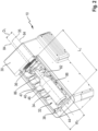
- the drawings show a beverage cooler 10 according to an embodiment.
- the beverage cooler 10 comprises a housing 12.
- the housing 12 comprises a housing body 14 and a lid 16.
- the lid 16 is hinged to the housing body 14 so as to be rotatable about an axis of rotation 18 being oriented horizontally.
- the lid 16 may in use be moved upward and downward to open and close the later described cooling chamber 32 allowing the insertion and removal of a beverage container 34.
- the lid may have a recess 20 embodying a handle.
- the housing 12 has a length L, a width W and a height H.
- the length L is larger than the width W.
- the housing 12 is elongated.
- the housing 12 is basically parallelepiped.
- the housing 12 has first and second opposite longitudinal side walls 22 and first and second opposite transverse side walls 24.
- One or two of the side walls may have a grid 26 allowing the exchange of air between the interior of the housing 12 and the exterior of the housing 12.
- a grid 26 is provided in each of the first and second longitudinal side walls 22 adjacent a transverse side wall 24 and a bottom 28.
- the bottom 28 serves as a support for supporting the beverage cooler 10 on a horizontal surface such as a table or a kitchen countertop.
- the lid 16 forms a top 30 of the housing 12 opposite to the bottom 28.
- the beverage cooler 10 further comprises a cooling chamber 32 part of which is shown in Figure 2 .
- the cooling chamber 32 in the present embodiment is defined by the housing body 14 and the lid 16. With the lid 16 in the closed position, the cooling chamber is a closed space.
- a sealing 40 is provided in the housing body 14 to seal the interface between the lid 16 and the housing body 14.
- the cooling chamber 32 as well has a length L c , a width W c and a height H c (shown in Figure 4 ).
- the length L c of the cooling chamber 32 is larger than its width W c .
- the cooling chamber 32 is elongated. In one example, the length L c is between 3 times and 5 times larger than the width W c .
- the length L c may be in the range of 320 mm and 420 mm or 320 mm and 385 mm, preferably between 320 mm and 375 mm.
- the length L c of the cooling chamber 32 may be between 320 mm and 365 mm.
- the length L c of the cooling chamber is particularly governed by the largest height of a bottle 34 to be accommodated in the cooling chamber.
- An example may be a flail bottle or slender bottle, e.g. used for Riesling, having a height between 300 and 375 mm.
- Another example may be a burgundy bottle, e.g. used for Chardonnay, usually having a height between 300 mm and 320 mm.
- the upper limit may be in the range of 420 mm.
- the width W c of the cooling chamber 32 may be between 100 mm and 190 mm. Again, the width W c of the cooling chamber 32 is particularly governed by the largest diameter of a beverage container to be accommodated. In this context, the diameter of a burgundy bottle is usually between 78 mm and 90 mm and that of a flail bottle is usually between 60 mm to 82 mm. If baffle plates are provided (see below), the width may be larger and preferably between 120 mm and 180 mm. Without baffles plates, a smaller width between 100 mm and 140 mm may be selected.
- the height H c may be in a similar range as the width.
- the height H c may be in the range of 120 mm and 200 mm. Similar as the width W c , the height H c is particularly governed by the largest diameter of a beverage container to be accommodated. Again, if baffle plates are provided, the height HC may be larger (between 120 mm and 200 mm) as compared to a cooling chamber without baffle plates (between 110 mm and 150 mm).
- the cooling chamber 32 has an internal volume of less than 15,000 cm 3 or less than 12,000 cm 3 or less than 10,000 cm 3 , excluding any internal mechanisms or features such as the baffle plates or the rotating mechanism described above.
- the internal volume may have a minimum size of 6,000 cm 3 or 4,000 cm 3 .
- the cooling chamber 32 is generally parallelepiped being limited by first and second opposite longitudinal side walls 42 and first and second opposite transverse side walls 44.
- the cooling chamber 32 is basically rectangular with rounded corners.
- the first and second opposite longitudinal side walls 42 extend in the longitudinal direction (length L c ) of the cooling chamber corresponding to the longitudinal direction of the housing 12 (length L).
- the first and second longitudinal side walls 42 extend parallel to the longitudinal center axis 35 of the beverage container 34.
- the first and second transverse side walls 44 extend along the width W c direction of the cooling chamber 32 and in the present embodiment also the width direction W of the housing 12.
- the first and second transverse side walls 44 extend perpendicular to the longitudinal center axis 35 of the beverage container 34.
- first and second transverse side walls 44 are located at the respective ends of the beverage containers 34 along the longitudinal center axis 35 of the beverage container 34.
- the beverage container 34 in the present invention is oriented horizontally, i.e. with is longitudinal center axis 35 being parallel to the bottom 28 of the housing 12.
- the cooling chamber 12 further comprises a bottom 48 and a top 50, wherein the top is located in the lid 16 (see Figure 4 ).
- the lid 16 may have hollow portions 76 so that the air within the hollow portion 76 may serve as insulation material for insulating the cooling chamber 32.
- the cooling chamber 32 comprises an air inlet 36 and an air outlet 38.
- two air outlets 38 are provided.
- the air inlet 36 is arranged in the first transverse side wall and the air outlets are positioned in the first and second longitudinal side walls 42 adjacent to the second transverse side wall 44.
- the cooling chamber 32 comprises a plurality of baffle plates 46 (8 in the embodiment depicted in Figure 2 and 10 in the simulation of Figure 6 ).
- the baffle plates 46 protrude from the first and second longitudinal side walls 42 as well as from the bottom 48 and the top 50 towards a center axis (the center axis 35 of the beverage containers 34). Therefore, the baffle plates extend perpendicular to the flow direction of the later described air flow through the cooling chamber 32.
- a free or leading edge 52 of the baffle plate 46 defines an area within the cooling chamber and is sized to accommodate the beverage containers 34 (see Figure 4 ).
- the baffle plates 46 may be offset on the opposite longitudinal side walls 42. To put it differently, a baffle plate 46 on one of the longitudinal side walls 44 may be positioned intermediate two adjacent baffle plates 46 on the opposite longitudinal side wall 44.
- the beverage cooler 10 further comprises an air flow circuit.
- the air flow circuit is constituted by the air inlet 36, the cooling chamber 32, the air outlet/-s 38 and a return passage 54.
- the return passage 54 extends from the air outlet/-s 38 parallel to the first and second longitudinal side walls 42 as best visible from Figures 4 and 5 .
- the return passage 54 may comprise a return chamber 56 located at an end of the return passage 54 opposite to the air outlet/-s 38.
- the return passage 54 extends from the air outlet/-s 38 via the optional return chamber 56 to the air inlet 36.
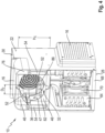
- the beverage cooler 10 comprises a refrigerating device 58 best visible from Figure 3 .
- the refrigerating device 58 is a vapor compression refrigerator.
- the refrigerating device 58 comprises a compressor 60, an evaporator 62, an expansion mechanism not visible in the drawings (here the form of the capillary tube) and a condenser 64.
- two condensers 64 are provided in order to increase the cooling capacity. Yet, only one condenser 64 may be sufficient.
- the evaporator 62 and/or the condensers 64 may be fin-tube-type heat exchangers.
- the compressor 60, the evaporator 62, the expansion mechanism and the condensers 64 are connected by refrigerant pipes 66 forming a refrigerant circuit and containing a refrigerant.
- the refrigerant is R290 or R600A. Yet, other refrigerants may as well be used.
- the compressor 60, the expansion mechanism and the condensers 64 are located in a lower portion of the housing 12. Particularly, the compressor 60 and the condenser 64 are mounted on a bottom plate 68 of the housing 12 and comprising the bottom 28. In this context, the condensers 64 are located adjacent and parallel to the longitudinal side walls 22 of the housing 12 adjacent to the grids 26.
- a fan 70 particularly an axial fan, is located between the condenser/-s 64 and the grid/-s 16 or the condenser/-s may be located between the fan/-s 70 and the grid/-s 16.
- a plurality of holes 72 is further provided in the first transverse side wall 24 of the housing 12.
- outdoor air may be drawn in via the grids 16 by means of the fan 70, passes through the condensers 64 and may again be exhausted from the interior of the housing 12 via the holes 72 to the outside.
- heat may be exchanged between the sucked in outdoor air and the refrigerant flowing through the condensers 66 before the outdoor air is again exhausted.
- the compressor 60, the condenser 64 and the expansion mechanism are located below the cooling chamber 32.
- the evaporator 62 is in the present embodiment located adjacent to the first transverse side wall 44 of the cooling chamber 32 comprising the air inlet 36.
- a fan 74 for inducing an airstream through the air flow circuit is also located in the vicinity or adjacent the first transverse side wall 44 of the cooling chamber 32.
- the evaporator 62 is sandwiched between the first transverse side wall 44 and the fan 74.
- the fan 74 is an axial fan.
- the fan 74 as? the fans 72 may provide for an air flow rate of at least 0.01 m 3 /s, preferably 0.05 m 3 /s.
- an air flow is induced in a closed loop.
- air is flown by the fan 74 to pass through the evaporator 62, wherein the air exchanges heat with the refrigerant flowing through the evaporator 62.
- the air is cooled, and heat is transferred from the air to the refrigerant for evaporating the refrigerant in the evaporator 62.
- the air flows via the air inlet 36 into the cooling chamber 32.
- the cool air introduced into the cooling chamber 32 flows along the surfaces of the beverage container 34 and past the beverage container 34 towards the air outlet 38 at the opposite end of the cooling chamber 32.
- the baffle plates 46 form dead spaces 47 in which the cool air may circulate (see simulation in Figure 6 ).
- the cool air When the cool air has reached the air outlets 38, it enters the return passage 54, flows to the return chamber 56 and is sucked in by the fan 74 and again flown through the evaporator 62 for cooling.
- the evaporator 62 is positioned in the air flow circuit upstream of the air inlet 36 in the flow direction of the air flow in the air flow circuit.
- the fan is arranged in the air flow circuit.
- the return passage connects the air outlet/-s 38 and the air inlet 36.
- the cooling chamber 32 forms a passage that connects the air inlet 36 and the air outlet/-s 38.
- the volumetric flow rate of the air flow induced by the fan 74 may in the cooling chamber be between 0.005 m 3 /s and 0.03 m 3 /s, preferably 0.01 and 0.03 m 3 /s and most preferably between 0.02 m 3 /s and 0.03 m 3 /s. It is also clear, that the volumetric flow rate in the dead spaces 47 formed by the baffle plates 46 is by far slower. Hence, the above volumetric flow rate particularly relates to the air volumetric air flow in the longitudinal direction of the cooling chamber 32 or at the air inlet.
- the volumetric flow rate of the air flow in the return passage 54 may be larger than in the cooling chamber 32 and preferably between 0.03 m 3 /s and 0.05 m 3 /s.
- the refrigerant in the evaporator 62 is vaporized and, hence, gaseous.
- the gaseous refrigerant is returned to the compressor 60.
- the refrigerant compressed in the compressor 60 is subsequently fed to the condensers 64.
- the refrigerant is condensed by transferring heat from the refrigerant to the outdoor air sucked in and flown through the condenser 64 by the fans 70.
- the condensed and, hence, liquid refrigerant passes through the expansion mechanism (capillary tube or expansion valve) being expanded. Due to the expansion, the refrigerant will change to a two-phase state, i.e. liquid and gas (vapor).
- the two-phase refrigerant is subsequently fed to the evaporator 62 in which the refrigerant is fully vaporized by taking up the heat from the air passed through the evaporator 62 by the fan 74, thereby cooling the air.
- the beverage cooler 10 comprises a rotating mechanism 78 for rotating the beverage container 34 (see particularly Figures 2 and 3 ).
- the rotating mechanism 78 comprises a rotatable support 80 comprising two distanced axes 82.
- the axes 82 are rotatable about their center axes 84.
- Each of the axes 82 comprises a plurality of high friction (e.g. rubber) support rings 86 for supporting the beverage container 34.
- the beverage container 34 particularly rests on the support rings 86.
- the distance D 1 between the axes 82 is about 60 mm. More important, however, is the distance D 2 between the outer circumferential surfaces of opposite support rings 86.
- the distance D 2 is between 48 mm and 50 mm and preferably 49 mm.
- the distance D 2 is primarily governed by the minimum diameter of the beverage container 34 to be accommodated in the cooling chamber 32, e.g. the diameter of a 0.25 liter Red Bull ® can. Yet, also the largest diameter of the beverage container 34 to be accommodated in the cooling chamber 32 has some influence. The distance should be large enough to also stably support those beverage containers 34 having a larger diameter.
- the rotating mechanism 78 comprises an electric motor 88.
- the electric motor 88 is located below the bottom 48 of the cooling chamber 32.
- the electric motor 88 has a driving axis 90 parallel to the longitudinal extension of the axes 82 and protruding beyond the second transverse side wall 44 of the cooling chamber 32.
- a driving gear 92 is mounted to the driving axis 19.
- Driven gears 94 are mounted at the respective ends of the axes 82 which protrude through the second transverse side wall 44.
- the driven gears 94 meshing with the driving gear 92. Due to the different diameters of the driven gears 94 and the driving gear 92, they form a transmission 96.
- the electric motor 88 gradually increases its speed.
- the rotational speed of the driving axis 90 gradually increases.
- the rotation of the driving axis 90 is transferred via the driving gear 92 to the driven gears 94, whereby the axes 82 are rotated both in the same rotational direction. Due to the high friction support rings 86 in contact with the outer circumference of the beverage container 34, also the beverage container 34 is rotated.
- the rotational speed of the electric motor 88 may be up to 10,000 rpm.
- the rotational speed of the axes 82 may be up to 1,000 rpm.
- the rotational speed of the beverage container 34 may be up to 400 rpm.
- the rotating mechanism is configured to rotate the beverage container between 50 and 400 rpm.
- a beverage cooler having only one cooling chamber 32 has been described. Yet, it is also possible to provide more than one cooling chamber 32, e.g. two cooling chambers 32. In this instance, however, the two cooling chambers 32 will be separated by an intermediate partition wall so as to obtain the beneficial heat transfer between the airflow through the cooling chamber and the beverage container 34.
- the beverage cooler may as well be configured for being accommodated in a drawer.
- the height H of the housing 12 should be not more than 29 mm. According to such an embodiment, the components of the refrigerating device 58 will most likely be arranged at the side of the cooling chamber 32, i.e. adjacent one of the longitudinal sidewalls 42.
- the airflow circuit has been described as a completely closed loop with no exchange of air between the airflow circuit and external air. Yet, it is also conceivable to provide the airflow circuit with an external air inlet and/or an external air outlet to introduce air from the outside of the housing 12 and/or exhaust air to the outside of the housing 12 and thereby increase the volume flow.
- a radial fan may be used with the benefit of increasing the volume flow. The same applies to the fans 70.
- the evaporator 62 and the fan 74 have been described as being positioned adjacent the first transverse side wall 44 of the cooling chamber 32. Yet, the evaporator 62 and/or the fan 74 may also be positioned below the cooling chamber 32. In this instance, but also in other cases, the return passage may pass along the bottom 48 of the cooling chamber 32 from the air outlet/-s 38 back to the air inlet 36 rather than along the longitudinal sidewalls 42 of the cooling chamber 32 as described.
- Another possible embodiment arranges the evaporator 62 and the fan 74 adjacent to one of the longitudinal sidewalls 42 of the cooling chamber 32 (see second embodiment) or provides an evaporator 62 and a fan 74 at each of the longitudinal sidewalls 42 of the cooling chamber 32.
- two air inlets 36 may be provided.
- the air inlet 36 may be provided in the longitudinal sidewall/-s 42 instead of the first transverse side wall 44.
- beverage cooler 10 is not limited in this regard and any beverage container including bottles of any kind and cans can be cooled.
- the lid 116 is configured to be rotatable about a vertical axis of rotation 118 (see Figure 7 ). As a result, the lid 116 is comparable to a door. Thus, thermal isolation of the cooling chamber 132 by the hollow portion 176 may be simplified as compared to the first embodiment.
- cooling chamber 132 omits the baffle plates 46 described with respect to the first embodiment. It is to be understood that either the first embodiment may omit the baffles 46 as well or the second embodiment may be provided with similar baffles.
- the air flow circuit is configured differently. As will be apparent from Figure 9 , the evaporator 162 is arranged along one of the longitudinal side walls 142 of the cooling chamber 132. As a result, the heat transfer surface may be enlarged as compared to the first embodiment improving cooling efficiency.
- two fans 174 are arranged above the top (top wall) 150 of the cooling chamber 132. It is to be understood that only one fan or more than two fans 174 may be provided. The provision of two of the fans 174 provides for a larger air flow rate through the cooling chamber 132 as compared with one fan 74 embodied in the first embodiment.
- the fans 174 are radial fans (centrifugal fans). The air is drawn in axially (parallel to the drive axis) of the fan 174 and deflected by the rotation of the radial impeller through 90° and blown out radially.
- the fans 174 are, hence, configured to suck air from the cooling chamber 132. Accordingly, air outlets 138 are arranged in the top 130 and the fans 174 suck air from the cooling chamber through the air outlets 138 into the return chamber 156.
- the air flows through the return passage 154 in which the evaporator 162 is positioned.
- the cooled air is reintroduced into the cooling chamber 132 via air inlets 136 positioned in the bottom 148 of the cooling chamber 132.
- the cooled air is, hence, flown onto a circumferential surface of the beverage container (not shown in Figure 9 ) in a direction perpendicular to the longitudinal center axis 135 of the beverage container.
- One of the air inlets 136 is even flush with the center axis 135 so that the cooled air is flown onto the circumferential surface of the beverage container in a radial direction.
- the different airflow circuit and the different arrangement of the fans 174 and the evaporator 162 provide for a higher cooling efficiency and a larger air flow rate through the cooling chamber thereby enhancing the speed with which the fluid in the beverage container may be cooled.
- the length of the beverage cooler 110 along the longitudinal extension (longitudinal center axis 135) of the beverage container may be reduced by the arrangement of the evaporator 162 along a side wall 142 of the cooling chamber 132 and arranging the fans 174 above the top 150 of the cooling chamber 132.
- the second embodiment also implements differently configured support rings 186. Whereas the support rings 86 in the first embodiment are cylindrical elements, the second embodiment embodies a plurality of O-rings.
Landscapes
- Engineering & Computer Science (AREA)
- Chemical & Material Sciences (AREA)
- Combustion & Propulsion (AREA)
- Physics & Mathematics (AREA)
- Mechanical Engineering (AREA)
- Thermal Sciences (AREA)
- General Engineering & Computer Science (AREA)
- Devices That Are Associated With Refrigeration Equipment (AREA)
Claims (15)
- Getränkekühler (10; 110), umfassend:ein Gehäuse (12; 112), das einen Gehäusekörper (14; 114) und einen Deckel (16; 116) aufweist, wobei der Gehäusekörper (14; 114) und der Deckel (16; 116) eine längliche Kühlkammer (32; 132) bilden, die eine Länge (Lc) aufweist, die größer ist als eine Breite (Wc), und die so konfiguriert ist, dass sie nur eine Flasche Wein oder Schaumwein gleichzeitig so aufnimmt, dass eine Längsmittelachse (35; 135) der Flasche (34) parallel zu der Länge (Lc) der Kühlkammer (32; 132) ist, wobei die Kühlkammer eine Einführöffnung zum Einführen der Flasche in die Kühlkammer (32; 132) aufweist, wobei der Deckel (16; 116) die Einführöffnung schließt, wobei die Kühlkammer (32; 132) einen Lufteinlass (36; 136) und einen Luftauslass (38; 138) umfasst,einen Luftströmungskreis, der den Lufteinlass (36; 136), die Kühlkammer (32; 132) und den Luftauslass (38; 138) umfasst,ein Gebläse (74; 174), das im Luftströmungskreis angeordnet ist zum Einleiten einer Luftströmung in den Luftströmungskreis in einer Luftströmungsrichtung,einen Drehmechanismus (78; 178) zum Drehen der Flasche (34) um die Längsmittelachse (35; 135); undeine Kühlvorrichtung (58), die einen Kompressor (60), einen Verdampfer (62; 162), einen Expansionsmechanismus und einen Verflüssiger (64) umfasst, die in einem Kühlmittelkreislauf verbunden sind, der ein Kühlmittel enthält, wobei der Verdampfer (62; 162) im Luftströmungskreis stromaufwärts vom Lufteinlass (36; 136) in der Luftströmungsrichtung positioniert ist zum Austauschen von Wärme zwischen der Luftströmung und dem Kühlmittel im Kühlmittelkreislauf, wobei der Deckel (16; 116) zum Einführen der Flasche in die Kühlkammer (32; 132) beweglich mit dem Gehäusekörper verbunden ist und die Kühlvorrichtung (58) im Gehäuse (12; 112) angeordnet ist.
- Getränkekühler nach Anspruch 1, wobei die Breite (Wc) und/oder Höhe (Hc) der Kühlkammer (32; 132) rechtwinklig zur Längsausdehnung der Kühlkammer (32; 132) zwischen 100 mm und 190 mm beträgt.
- Getränkekühler nach Anspruch 1 oder 2, wobei die Länge (Lc) der Kühlkammer (32; 132) entlang der Längsausdehnung der Kühlkammer (32; 132) zwischen 320 mm und 420 mm beträgt.
- Getränkekühler nach einem der vorstehenden Ansprüche, wobei der Lufteinlass (36; 136) so konfiguriert ist, dass er die Luftströmung auf eine Umfangsoberfläche der Flasche (34), vorzugsweise rechtwinklig zu der Längsmittelachse und/oder in einer radialen Richtung der Flasche (34) lenkt.
- Getränkekühler nach einem der vorstehenden Ansprüche, wobei die Kühlkammer (32; 132) eine erste Seitenwand (42; 44) und ein zweite Seitenwand (42; 44) gegenüber der ersten Seitenwand aufweist, wobei der Lufteinlass (36; 136) in der ersten Seitenwand gebildet ist und der Luftauslass (38; 138) angrenzend zu oder in der zweiten Seitenwand gebildet ist.
- Getränkekühler nach Anspruch 5, wobei die erste und zweite Seitenwand (42; 44) an jeweiligen Enden in der Längsrichtung der Kühlkammer (32; 132) gelegen sind.
- Getränkekühler nach Anspruch 5 oder 6, wobei der Verdampfer (62; 162) und/oder das Gebläse (74; 174) angrenzend zur ersten Seitenwand (42; 44) außerhalb der Kühlkammer (32; 132) angeordnet ist/sind.
- Getränkekühler nach Anspruch 7, wobei der Verdampfer (62; 162) zwischen der ersten Seitenwand (42; 44) und dem Gebläse (74; 174) zwischengelegt ist.
- Getränkekühler nach einem der vorstehenden Ansprüche, wobei der Luftströmungskreis einen Rückführkanal (54) umfasst, der den Luftauslass (38; 138) und den Lufteinlass (36; 136) verbindet.
- Getränkekühler nach einem der vorstehenden Ansprüche, wobei die Kühlkammer (32; 132) eine Vielzahl von Prallblechen (46) aufweist, die sich vorzugsweise rechtwinklig zur Luftströmungsrichtung erstrecken.
- Getränkekühler nach einem der vorstehenden Ansprüche, wobei der Luftströmungskreis im Gehäusekörper (14; 114) und/oder dem Deckel (16; 116) gebildet werden kann.
- Getränkekühler nach einem der vorstehenden Ansprüche, wobei der Drehmechanismus (78, 178) eine drehbare Stütze (80, 180), die zum drehbaren Stützen der Flasche (34) in der Kühlkammer (32; 132) angeordnet ist, und einen Motor (88) zum Drehen der Stütze (80; 180) umfasst, wobei der Motor (88) vorzugsweise unter oder an einem Längsende der Kühlkammer gelegen ist.
- Getränkekühler nach Anspruch 12, wobei die drehbare Stütze (80; 180) zwei beabstandete Achsen (82; 182) umfasst, die sich entlang der Längsrichtung der Kühlkammer (32; 132) erstrecken.
- Getränkekühler nach einem der vorstehenden Ansprüche, wobei der Kompressor (60) und/oder der Verflüssiger (64) und/oder der Expansionsmechanismus unter der Kühlkammer (32; 132) angeordnet ist/sind.
- Getränkekühler nach einem der vorstehenden Ansprüche, wobei die Kühlkammer (32; 132) ein Innenvolumen aufweist, das weniger als 15.000 cm3, vorzugsweise weniger als 12.000 cm3, besonders bevorzugt weniger als 10.000 cm3 beträgt.
Applications Claiming Priority (2)
| Application Number | Priority Date | Filing Date | Title |
|---|---|---|---|
| EP21173255.7A EP4089351A1 (de) | 2021-05-11 | 2021-05-11 | Getränkekühler |
| PCT/EP2022/062577 WO2022238371A1 (en) | 2021-05-11 | 2022-05-10 | Beverage cooler |
Publications (3)
| Publication Number | Publication Date |
|---|---|
| EP4337900A1 EP4337900A1 (de) | 2024-03-20 |
| EP4337900B1 true EP4337900B1 (de) | 2025-04-09 |
| EP4337900C0 EP4337900C0 (de) | 2025-04-09 |
Family
ID=75914233
Family Applications (2)
| Application Number | Title | Priority Date | Filing Date |
|---|---|---|---|
| EP21173255.7A Withdrawn EP4089351A1 (de) | 2021-05-11 | 2021-05-11 | Getränkekühler |
| EP22728500.4A Active EP4337900B1 (de) | 2021-05-11 | 2022-05-10 | Getränkekühler |
Family Applications Before (1)
| Application Number | Title | Priority Date | Filing Date |
|---|---|---|---|
| EP21173255.7A Withdrawn EP4089351A1 (de) | 2021-05-11 | 2021-05-11 | Getränkekühler |
Country Status (6)
| Country | Link |
|---|---|
| US (1) | US20240247867A1 (de) |
| EP (2) | EP4089351A1 (de) |
| CN (1) | CN117295920A (de) |
| ES (1) | ES3027258T3 (de) |
| PL (1) | PL4337900T3 (de) |
| WO (1) | WO2022238371A1 (de) |
Families Citing this family (1)
| Publication number | Priority date | Publication date | Assignee | Title |
|---|---|---|---|---|
| CN120500604A (zh) * | 2022-12-19 | 2025-08-15 | 达沙服务有限公司 | 饮料冷却装置 |
Citations (5)
| Publication number | Priority date | Publication date | Assignee | Title |
|---|---|---|---|---|
| US2204804A (en) * | 1938-08-13 | 1940-06-18 | Westinghouse Electric & Mfg Co | Bottle cooler |
| JP2003214753A (ja) * | 2002-01-21 | 2003-07-30 | Hoshizaki Electric Co Ltd | 飲料水の過冷却用冷却装置 |
| US20060207279A1 (en) * | 2005-03-18 | 2006-09-21 | Carrier Corporation | Refrigerated merchandiser |
| US20140053592A1 (en) * | 2012-08-21 | 2014-02-27 | Whirlpool Corporation | Chilling device for a domestic refrigerator |
| US20200018542A1 (en) * | 2018-07-12 | 2020-01-16 | Pepsico, Inc. | Beverage cooler |
Family Cites Families (8)
| Publication number | Priority date | Publication date | Assignee | Title |
|---|---|---|---|---|
| US4164851A (en) | 1977-12-19 | 1979-08-21 | Bryant Jon A | Beverage container cooler |
| US7343748B2 (en) * | 2005-12-29 | 2008-03-18 | Whirlpool Corporation | Device for rapidly chilling articles in a refrigerator |
| KR101702131B1 (ko) * | 2010-07-16 | 2017-02-02 | 엘지전자 주식회사 | 냉각 장치 및 냉각 장치가 구비된 냉장고 |
| WO2012090209A2 (en) | 2010-12-29 | 2012-07-05 | Roike's Ideas Ltd. | Methods and devices of accelerated cooling |
| DE102014202925A1 (de) | 2014-02-18 | 2015-08-20 | BSH Hausgeräte GmbH | Kältegerät und Flaschenkühler dafür |
| WO2015162631A2 (en) * | 2014-04-25 | 2015-10-29 | Innomine Holding Private Limited | Apparatus for cooling |
| DE102014224117B4 (de) | 2014-11-26 | 2016-09-08 | Koenig & Bauer Ag | Registermarke |
| CN107477954B (zh) * | 2016-06-08 | 2020-10-13 | 青岛海高设计制造有限公司 | 一种饮料速冷间室 |
-
2021
- 2021-05-11 EP EP21173255.7A patent/EP4089351A1/de not_active Withdrawn
-
2022
- 2022-05-10 PL PL22728500.4T patent/PL4337900T3/pl unknown
- 2022-05-10 EP EP22728500.4A patent/EP4337900B1/de active Active
- 2022-05-10 CN CN202280034618.2A patent/CN117295920A/zh active Pending
- 2022-05-10 US US18/560,353 patent/US20240247867A1/en not_active Abandoned
- 2022-05-10 ES ES22728500T patent/ES3027258T3/es active Active
- 2022-05-10 WO PCT/EP2022/062577 patent/WO2022238371A1/en not_active Ceased
Patent Citations (5)
| Publication number | Priority date | Publication date | Assignee | Title |
|---|---|---|---|---|
| US2204804A (en) * | 1938-08-13 | 1940-06-18 | Westinghouse Electric & Mfg Co | Bottle cooler |
| JP2003214753A (ja) * | 2002-01-21 | 2003-07-30 | Hoshizaki Electric Co Ltd | 飲料水の過冷却用冷却装置 |
| US20060207279A1 (en) * | 2005-03-18 | 2006-09-21 | Carrier Corporation | Refrigerated merchandiser |
| US20140053592A1 (en) * | 2012-08-21 | 2014-02-27 | Whirlpool Corporation | Chilling device for a domestic refrigerator |
| US20200018542A1 (en) * | 2018-07-12 | 2020-01-16 | Pepsico, Inc. | Beverage cooler |
Also Published As
| Publication number | Publication date |
|---|---|
| WO2022238371A1 (en) | 2022-11-17 |
| CN117295920A (zh) | 2023-12-26 |
| EP4089351A1 (de) | 2022-11-16 |
| US20240247867A1 (en) | 2024-07-25 |
| ES3027258T3 (en) | 2025-06-13 |
| EP4337900A1 (de) | 2024-03-20 |
| PL4337900T3 (pl) | 2025-06-09 |
| EP4337900C0 (de) | 2025-04-09 |
Similar Documents
| Publication | Publication Date | Title |
|---|---|---|
| CN102713464B (zh) | 安装在台座内的制冷系统 | |
| US20140165594A1 (en) | Magneto caloric device with continuous pump | |
| US20090158768A1 (en) | Temperature controlled devices | |
| CN1648562A (zh) | 冰箱 | |
| KR20090006418A (ko) | 냉장고 | |
| EP4337900B1 (de) | Getränkekühler | |
| JP2012032013A (ja) | 冷蔵庫 | |
| KR20050077761A (ko) | 가열/냉각 시스템 | |
| WO2004113807A1 (ja) | 冷却装置 | |
| JP5405158B2 (ja) | 蒸発器 | |
| CN221349496U (zh) | 冰箱 | |
| CN219693668U (zh) | 一种制冷机散热装置 | |
| KR20110041659A (ko) | 양문형 냉장고 | |
| JP4583230B2 (ja) | 低温ショーケース | |
| CN223232530U (zh) | 一种饮品机 | |
| CN221527012U (zh) | 冰箱 | |
| WO2010092625A1 (ja) | 冷蔵庫 | |
| KR100565490B1 (ko) | 상부 개폐식 직냉식 냉장고 | |
| JP2005345063A (ja) | 冷蔵庫 | |
| RU2773123C2 (ru) | Холодильник | |
| KR100429625B1 (ko) | 냉장고의 냉장실 유로 구조 | |
| KR200225865Y1 (ko) | 냉장고의 기계실 | |
| JP2005055164A (ja) | 冷却装置 | |
| JP2008241113A (ja) | 冷凍冷蔵庫 | |
| KR200345577Y1 (ko) | 냉장고의 기계실 |
Legal Events
| Date | Code | Title | Description |
|---|---|---|---|
| STAA | Information on the status of an ep patent application or granted ep patent |
Free format text: STATUS: UNKNOWN |
|
| STAA | Information on the status of an ep patent application or granted ep patent |
Free format text: STATUS: THE INTERNATIONAL PUBLICATION HAS BEEN MADE |
|
| PUAI | Public reference made under article 153(3) epc to a published international application that has entered the european phase |
Free format text: ORIGINAL CODE: 0009012 |
|
| STAA | Information on the status of an ep patent application or granted ep patent |
Free format text: STATUS: REQUEST FOR EXAMINATION WAS MADE |
|
| 17P | Request for examination filed |
Effective date: 20231206 |
|
| AK | Designated contracting states |
Kind code of ref document: A1 Designated state(s): AL AT BE BG CH CY CZ DE DK EE ES FI FR GB GR HR HU IE IS IT LI LT LU LV MC MK MT NL NO PL PT RO RS SE SI SK SM TR |
|
| DAV | Request for validation of the european patent (deleted) | ||
| DAX | Request for extension of the european patent (deleted) | ||
| GRAP | Despatch of communication of intention to grant a patent |
Free format text: ORIGINAL CODE: EPIDOSNIGR1 |
|
| STAA | Information on the status of an ep patent application or granted ep patent |
Free format text: STATUS: GRANT OF PATENT IS INTENDED |
|
| INTG | Intention to grant announced |
Effective date: 20241209 |
|
| GRAS | Grant fee paid |
Free format text: ORIGINAL CODE: EPIDOSNIGR3 |
|
| GRAA | (expected) grant |
Free format text: ORIGINAL CODE: 0009210 |
|
| STAA | Information on the status of an ep patent application or granted ep patent |
Free format text: STATUS: THE PATENT HAS BEEN GRANTED |
|
| AK | Designated contracting states |
Kind code of ref document: B1 Designated state(s): AL AT BE BG CH CY CZ DE DK EE ES FI FR GB GR HR HU IE IS IT LI LT LU LV MC MK MT NL NO PL PT RO RS SE SI SK SM TR |
|
| REG | Reference to a national code |
Ref country code: GB Ref legal event code: FG4D |
|
| REG | Reference to a national code |
Ref country code: CH Ref legal event code: EP |
|
| REG | Reference to a national code |
Ref country code: IE Ref legal event code: FG4D |
|
| U01 | Request for unitary effect filed |
Effective date: 20250409 |
|
| U07 | Unitary effect registered |
Designated state(s): AT BE BG DE DK EE FI FR IT LT LU LV MT NL PT RO SE SI Effective date: 20250415 |
|
| REG | Reference to a national code |
Ref country code: ES Ref legal event code: FG2A Ref document number: 3027258 Country of ref document: ES Kind code of ref document: T3 Effective date: 20250613 |
|
| U20 | Renewal fee for the european patent with unitary effect paid |
Year of fee payment: 4 Effective date: 20250519 |
|
| PGFP | Annual fee paid to national office [announced via postgrant information from national office to epo] |
Ref country code: PL Payment date: 20250428 Year of fee payment: 4 |
|
| PGFP | Annual fee paid to national office [announced via postgrant information from national office to epo] |
Ref country code: ES Payment date: 20250603 Year of fee payment: 4 |
|
| PGFP | Annual fee paid to national office [announced via postgrant information from national office to epo] |
Ref country code: CH Payment date: 20250601 Year of fee payment: 4 |
|
| PGFP | Annual fee paid to national office [announced via postgrant information from national office to epo] |
Ref country code: TR Payment date: 20250506 Year of fee payment: 4 |
|
| PGFP | Annual fee paid to national office [announced via postgrant information from national office to epo] |
Ref country code: IE Payment date: 20250507 Year of fee payment: 4 |
|
| PG25 | Lapsed in a contracting state [announced via postgrant information from national office to epo] |
Ref country code: NO Free format text: LAPSE BECAUSE OF FAILURE TO SUBMIT A TRANSLATION OF THE DESCRIPTION OR TO PAY THE FEE WITHIN THE PRESCRIBED TIME-LIMIT Effective date: 20250709 Ref country code: GR Free format text: LAPSE BECAUSE OF FAILURE TO SUBMIT A TRANSLATION OF THE DESCRIPTION OR TO PAY THE FEE WITHIN THE PRESCRIBED TIME-LIMIT Effective date: 20250710 |
|
| PG25 | Lapsed in a contracting state [announced via postgrant information from national office to epo] |
Ref country code: HR Free format text: LAPSE BECAUSE OF FAILURE TO SUBMIT A TRANSLATION OF THE DESCRIPTION OR TO PAY THE FEE WITHIN THE PRESCRIBED TIME-LIMIT Effective date: 20250409 |
|
| PG25 | Lapsed in a contracting state [announced via postgrant information from national office to epo] |
Ref country code: RS Free format text: LAPSE BECAUSE OF FAILURE TO SUBMIT A TRANSLATION OF THE DESCRIPTION OR TO PAY THE FEE WITHIN THE PRESCRIBED TIME-LIMIT Effective date: 20250709 |
|
| PG25 | Lapsed in a contracting state [announced via postgrant information from national office to epo] |
Ref country code: IS Free format text: LAPSE BECAUSE OF FAILURE TO SUBMIT A TRANSLATION OF THE DESCRIPTION OR TO PAY THE FEE WITHIN THE PRESCRIBED TIME-LIMIT Effective date: 20250809 |
|
| PG25 | Lapsed in a contracting state [announced via postgrant information from national office to epo] |
Ref country code: SM Free format text: LAPSE BECAUSE OF FAILURE TO SUBMIT A TRANSLATION OF THE DESCRIPTION OR TO PAY THE FEE WITHIN THE PRESCRIBED TIME-LIMIT Effective date: 20250409 |
|
| PG25 | Lapsed in a contracting state [announced via postgrant information from national office to epo] |
Ref country code: CZ Free format text: LAPSE BECAUSE OF FAILURE TO SUBMIT A TRANSLATION OF THE DESCRIPTION OR TO PAY THE FEE WITHIN THE PRESCRIBED TIME-LIMIT Effective date: 20250409 |
|
| PG25 | Lapsed in a contracting state [announced via postgrant information from national office to epo] |
Ref country code: SK Free format text: LAPSE BECAUSE OF FAILURE TO SUBMIT A TRANSLATION OF THE DESCRIPTION OR TO PAY THE FEE WITHIN THE PRESCRIBED TIME-LIMIT Effective date: 20250409 |
|
| PG25 | Lapsed in a contracting state [announced via postgrant information from national office to epo] |
Ref country code: MC Free format text: LAPSE BECAUSE OF FAILURE TO SUBMIT A TRANSLATION OF THE DESCRIPTION OR TO PAY THE FEE WITHIN THE PRESCRIBED TIME-LIMIT Effective date: 20250409 |
|
| PLBE | No opposition filed within time limit |
Free format text: ORIGINAL CODE: 0009261 |
|
| STAA | Information on the status of an ep patent application or granted ep patent |
Free format text: STATUS: NO OPPOSITION FILED WITHIN TIME LIMIT |
|
| REG | Reference to a national code |
Ref country code: CH Ref legal event code: L10 Free format text: ST27 STATUS EVENT CODE: U-0-0-L10-L00 (AS PROVIDED BY THE NATIONAL OFFICE) Effective date: 20260218 |
|
| 26N | No opposition filed |
Effective date: 20260112 |