EP4337558B1 - Umschlag, herstellungsverfahren und maschine - Google Patents
Umschlag, herstellungsverfahren und maschine Download PDFInfo
- Publication number
- EP4337558B1 EP4337558B1 EP22727932.0A EP22727932A EP4337558B1 EP 4337558 B1 EP4337558 B1 EP 4337558B1 EP 22727932 A EP22727932 A EP 22727932A EP 4337558 B1 EP4337558 B1 EP 4337558B1
- Authority
- EP
- European Patent Office
- Prior art keywords
- envelope
- per
- flap
- precut
- coat
- Prior art date
- Legal status (The legal status is an assumption and is not a legal conclusion. Google has not performed a legal analysis and makes no representation as to the accuracy of the status listed.)
- Active
Links
Images


Classifications
-
- B—PERFORMING OPERATIONS; TRANSPORTING
- B65—CONVEYING; PACKING; STORING; HANDLING THIN OR FILAMENTARY MATERIAL
- B65D—CONTAINERS FOR STORAGE OR TRANSPORT OF ARTICLES OR MATERIALS, e.g. BAGS, BARRELS, BOTTLES, BOXES, CANS, CARTONS, CRATES, DRUMS, JARS, TANKS, HOPPERS, FORWARDING CONTAINERS; ACCESSORIES, CLOSURES, OR FITTINGS THEREFOR; PACKAGING ELEMENTS; PACKAGES
- B65D27/00—Envelopes or like essentially-rectangular flexible containers for postal or other purposes having no structural provision for thickness of contents
- B65D27/12—Closures
- B65D27/14—Closures using adhesive applied to integral parts, e.g. flaps
-
- B—PERFORMING OPERATIONS; TRANSPORTING
- B31—MAKING ARTICLES OF PAPER, CARDBOARD OR MATERIAL WORKED IN A MANNER ANALOGOUS TO PAPER; WORKING PAPER, CARDBOARD OR MATERIAL WORKED IN A MANNER ANALOGOUS TO PAPER
- B31B—MAKING CONTAINERS OF PAPER, CARDBOARD OR MATERIAL WORKED IN A MANNER ANALOGOUS TO PAPER
- B31B70/00—Making flexible containers, e.g. envelopes or bags
- B31B70/02—Feeding or positioning sheets, blanks or webs
- B31B70/10—Feeding or positioning webs
-
- B—PERFORMING OPERATIONS; TRANSPORTING
- B31—MAKING ARTICLES OF PAPER, CARDBOARD OR MATERIAL WORKED IN A MANNER ANALOGOUS TO PAPER; WORKING PAPER, CARDBOARD OR MATERIAL WORKED IN A MANNER ANALOGOUS TO PAPER
- B31B—MAKING CONTAINERS OF PAPER, CARDBOARD OR MATERIAL WORKED IN A MANNER ANALOGOUS TO PAPER
- B31B70/00—Making flexible containers, e.g. envelopes or bags
- B31B70/14—Cutting, e.g. perforating, punching, slitting or trimming
- B31B70/146—Cutting, e.g. perforating, punching, slitting or trimming using tools mounted on a drum
-
- B—PERFORMING OPERATIONS; TRANSPORTING
- B31—MAKING ARTICLES OF PAPER, CARDBOARD OR MATERIAL WORKED IN A MANNER ANALOGOUS TO PAPER; WORKING PAPER, CARDBOARD OR MATERIAL WORKED IN A MANNER ANALOGOUS TO PAPER
- B31B—MAKING CONTAINERS OF PAPER, CARDBOARD OR MATERIAL WORKED IN A MANNER ANALOGOUS TO PAPER
- B31B70/00—Making flexible containers, e.g. envelopes or bags
- B31B70/14—Cutting, e.g. perforating, punching, slitting or trimming
- B31B70/16—Cutting webs
-
- B—PERFORMING OPERATIONS; TRANSPORTING
- B31—MAKING ARTICLES OF PAPER, CARDBOARD OR MATERIAL WORKED IN A MANNER ANALOGOUS TO PAPER; WORKING PAPER, CARDBOARD OR MATERIAL WORKED IN A MANNER ANALOGOUS TO PAPER
- B31B—MAKING CONTAINERS OF PAPER, CARDBOARD OR MATERIAL WORKED IN A MANNER ANALOGOUS TO PAPER
- B31B70/00—Making flexible containers, e.g. envelopes or bags
- B31B70/60—Uniting opposed surfaces or edges; Taping
- B31B70/62—Uniting opposed surfaces or edges; Taping by adhesives
-
- B—PERFORMING OPERATIONS; TRANSPORTING
- B31—MAKING ARTICLES OF PAPER, CARDBOARD OR MATERIAL WORKED IN A MANNER ANALOGOUS TO PAPER; WORKING PAPER, CARDBOARD OR MATERIAL WORKED IN A MANNER ANALOGOUS TO PAPER
- B31B—MAKING CONTAINERS OF PAPER, CARDBOARD OR MATERIAL WORKED IN A MANNER ANALOGOUS TO PAPER
- B31B70/00—Making flexible containers, e.g. envelopes or bags
- B31B70/74—Auxiliary operations
- B31B70/81—Forming or attaching accessories, e.g. opening devices, closures or tear strings
- B31B70/812—Applying patches, strips or strings on sheets or webs
- B31B70/8123—Applying strips
-
- B—PERFORMING OPERATIONS; TRANSPORTING
- B31—MAKING ARTICLES OF PAPER, CARDBOARD OR MATERIAL WORKED IN A MANNER ANALOGOUS TO PAPER; WORKING PAPER, CARDBOARD OR MATERIAL WORKED IN A MANNER ANALOGOUS TO PAPER
- B31B—MAKING CONTAINERS OF PAPER, CARDBOARD OR MATERIAL WORKED IN A MANNER ANALOGOUS TO PAPER
- B31B70/00—Making flexible containers, e.g. envelopes or bags
- B31B70/74—Auxiliary operations
- B31B70/81—Forming or attaching accessories, e.g. opening devices, closures or tear strings
- B31B70/813—Applying closures
-
- B—PERFORMING OPERATIONS; TRANSPORTING
- B65—CONVEYING; PACKING; STORING; HANDLING THIN OR FILAMENTARY MATERIAL
- B65D—CONTAINERS FOR STORAGE OR TRANSPORT OF ARTICLES OR MATERIALS, e.g. BAGS, BARRELS, BOTTLES, BOXES, CANS, CARTONS, CRATES, DRUMS, JARS, TANKS, HOPPERS, FORWARDING CONTAINERS; ACCESSORIES, CLOSURES, OR FITTINGS THEREFOR; PACKAGING ELEMENTS; PACKAGES
- B65D27/00—Envelopes or like essentially-rectangular flexible containers for postal or other purposes having no structural provision for thickness of contents
- B65D27/32—Opening devices incorporated during envelope manufacture
- B65D27/34—Lines of weakness
-
- B—PERFORMING OPERATIONS; TRANSPORTING
- B65—CONVEYING; PACKING; STORING; HANDLING THIN OR FILAMENTARY MATERIAL
- B65D—CONTAINERS FOR STORAGE OR TRANSPORT OF ARTICLES OR MATERIALS, e.g. BAGS, BARRELS, BOTTLES, BOXES, CANS, CARTONS, CRATES, DRUMS, JARS, TANKS, HOPPERS, FORWARDING CONTAINERS; ACCESSORIES, CLOSURES, OR FITTINGS THEREFOR; PACKAGING ELEMENTS; PACKAGES
- B65D31/00—Bags or like containers made of paper and having structural provision for thickness of contents
- B65D31/10—Bags or like containers made of paper and having structural provision for thickness of contents with gusseted sides
-
- B—PERFORMING OPERATIONS; TRANSPORTING
- B65—CONVEYING; PACKING; STORING; HANDLING THIN OR FILAMENTARY MATERIAL
- B65D—CONTAINERS FOR STORAGE OR TRANSPORT OF ARTICLES OR MATERIALS, e.g. BAGS, BARRELS, BOTTLES, BOXES, CANS, CARTONS, CRATES, DRUMS, JARS, TANKS, HOPPERS, FORWARDING CONTAINERS; ACCESSORIES, CLOSURES, OR FITTINGS THEREFOR; PACKAGING ELEMENTS; PACKAGES
- B65D33/00—Details of, or accessories for, sacks or bags
- B65D33/16—End- or aperture-closing arrangements or devices
- B65D33/18—End- or aperture-closing arrangements or devices using adhesive applied to integral parts, e.g. to flaps
-
- B—PERFORMING OPERATIONS; TRANSPORTING
- B31—MAKING ARTICLES OF PAPER, CARDBOARD OR MATERIAL WORKED IN A MANNER ANALOGOUS TO PAPER; WORKING PAPER, CARDBOARD OR MATERIAL WORKED IN A MANNER ANALOGOUS TO PAPER
- B31B—MAKING CONTAINERS OF PAPER, CARDBOARD OR MATERIAL WORKED IN A MANNER ANALOGOUS TO PAPER
- B31B2155/00—Flexible containers made from webs
-
- B—PERFORMING OPERATIONS; TRANSPORTING
- B31—MAKING ARTICLES OF PAPER, CARDBOARD OR MATERIAL WORKED IN A MANNER ANALOGOUS TO PAPER; WORKING PAPER, CARDBOARD OR MATERIAL WORKED IN A MANNER ANALOGOUS TO PAPER
- B31B—MAKING CONTAINERS OF PAPER, CARDBOARD OR MATERIAL WORKED IN A MANNER ANALOGOUS TO PAPER
- B31B2160/00—Shape of flexible containers
- B31B2160/20—Shape of flexible containers with structural provision for thickness of contents
-
- B—PERFORMING OPERATIONS; TRANSPORTING
- B31—MAKING ARTICLES OF PAPER, CARDBOARD OR MATERIAL WORKED IN A MANNER ANALOGOUS TO PAPER; WORKING PAPER, CARDBOARD OR MATERIAL WORKED IN A MANNER ANALOGOUS TO PAPER
- B31B—MAKING CONTAINERS OF PAPER, CARDBOARD OR MATERIAL WORKED IN A MANNER ANALOGOUS TO PAPER
- B31B70/00—Making flexible containers, e.g. envelopes or bags
- B31B70/74—Auxiliary operations
- B31B70/92—Delivering
- B31B70/98—Delivering in stacks or bundles
-
- B—PERFORMING OPERATIONS; TRANSPORTING
- B65—CONVEYING; PACKING; STORING; HANDLING THIN OR FILAMENTARY MATERIAL
- B65D—CONTAINERS FOR STORAGE OR TRANSPORT OF ARTICLES OR MATERIALS, e.g. BAGS, BARRELS, BOTTLES, BOXES, CANS, CARTONS, CRATES, DRUMS, JARS, TANKS, HOPPERS, FORWARDING CONTAINERS; ACCESSORIES, CLOSURES, OR FITTINGS THEREFOR; PACKAGING ELEMENTS; PACKAGES
- B65D27/00—Envelopes or like essentially-rectangular flexible containers for postal or other purposes having no structural provision for thickness of contents
- B65D27/06—Envelopes or like essentially-rectangular flexible containers for postal or other purposes having no structural provision for thickness of contents with provisions for repeated re-use
-
- B—PERFORMING OPERATIONS; TRANSPORTING
- B65—CONVEYING; PACKING; STORING; HANDLING THIN OR FILAMENTARY MATERIAL
- B65D—CONTAINERS FOR STORAGE OR TRANSPORT OF ARTICLES OR MATERIALS, e.g. BAGS, BARRELS, BOTTLES, BOXES, CANS, CARTONS, CRATES, DRUMS, JARS, TANKS, HOPPERS, FORWARDING CONTAINERS; ACCESSORIES, CLOSURES, OR FITTINGS THEREFOR; PACKAGING ELEMENTS; PACKAGES
- B65D27/00—Envelopes or like essentially-rectangular flexible containers for postal or other purposes having no structural provision for thickness of contents
- B65D27/32—Opening devices incorporated during envelope manufacture
- B65D27/38—Tearing-strings or -strips
Definitions
- the invention relates to an envelope formed by at least one sheet of flexible material, a method of manufacturing an envelope and a machine for manufacturing flexible envelopes.
- the document FR 1 270 400 describes a machine and method in which a strip is unrolled and then formed into a casing.
- the casing is flattened so that it has a first and a second wall, then the casing is cut into sections so that at each end of the section there remains a tab that extends the first or second wall.
- the tab is folded and glued by being folded down onto the wall other than the one from which the tab originated. This allows bags to be manufactured at a high speed with a wide variety of materials and formats.
- the document FR 786 579 shows several examples of this technique. It shows in particular on the figures 4 to 6 a manufacturing process in which the paper web is provided at regular intervals with transverse perforation lines, with one line in the center and two lines, axially offset from the center line on each selvage of the web.
- the casing is formed by folding each edge over the central portion and gluing the two edges together along a central junction so that the perforations form two transverse lines offset respectively on each of the faces of the casing.
- the casing thus formed passes between a pair of drive rollers which drive the casing at a constant speed.
- the front part of the casing is gripped by the folding device which comprises a counter-rotating drum and folding roller.
- the drum and the folding roller rotate with a peripheral speed greater than that of the pair of drive rollers.
- the folding roller comprises a bar adapted to pinch the front of the casing against the drum, so that the front part of the casing is pulled and separated by tearing along the perforations to form a section.
- a rear leg is thus formed on the section, as well as a front leg at the end of the casing. This front leg will be found on the next section.
- the leg front is folded by the folding device over a glued area to close the front part of the section.
- the roller also has a folding blade, placed just behind the bar, which pushes the casing into a clamp carried by the drum so as to fold the casing.
- the casing is formed with bellows that connect the first and second walls.
- the document WO 2016 097310 A1 shows an example of such bags.
- This document also shows a machine for forming an envelope from the casing using two stations, each comprising a pair of counter-rotating cylinders, the work of which allows the separation into sections and the tearing off of waste to reveal a tab at the front of the section on the same wall as the rear tab. Thus, after folding the tabs, they are applied to the same wall.
- the rear flap is provided with an adhesive layer, for example protected by protective means such as a sheet of silicone paper. This sheet can be removed, revealing the adhesive layer.
- the rear flap serves as a closing flap which can be folded by bringing the adhesive layer against the wall opposite to that from which the rear flap originates, so that the adhesive layer sticks to the wall and seals the envelope.
- the wall from which the tabs originate has a smooth face when the tabs are glued to the opposite face to close the envelope.
- waste removal is a limitation: on the one hand, it is found to be a limiting factor for the speed of bag manufacturing, and on the other hand, the large volume of waste is always a constraint to manage.
- the adjustment of such a machine requires high technical expertise. Changing bag formats takes a long time to adjust, especially when changing the width, because it is necessary to change the perforation methods.
- the document FR 1 270 400 also discloses a manufacturing process that can be used for envelopes.
- a continuous sheet of paper is unrolled and then cuts are made on the edges so as to release gluing seams symmetrical with respect to a longitudinal middle of the sheet and extending along an area of the sheet that is called an upper flap.
- the seams are folded longitudinally on the sheet and coated with glue on the upper face, opposite the upper flap.
- the sheet is cut into sections, for example by a clean cut and folded along a transverse fold to delimit a lower flap which is folded over the upper flap.
- the lower flap is thus glued to the seams and the container is delimited between the upper flap and the lower flap.
- the cut is made in such a way that a leg remains as an extension of the upper flap opposite the transverse fold.
- the document EP-3564146-A1 shows a bag-making process quite similar to that of FR 1 270 400 , but which differs in that no cutting is done at the selvedge.
- the flaps folded over each other are glued together along the selvedge. The process therefore does not generate any waste, but the useful width of the bag is reduced by the width of the areas glued to each other.
- this type of gluing is more fragile, because the stresses of spacing one flap in relation to the other are concentrated at the edge of the glued area.
- US 5,002,220 A discloses an envelope and a method of making an envelope.
- the invention aims to provide an envelope whose closure is of good quality and easy to produce. It also aims to provide a method and a machine for high-speed manufacturing of such envelopes, with or without gussets, which does not generate waste and is easy to adjust.
- the invention provides an envelope according to claim 1.
- Such an envelope is used by first detaching the pre-cut area and pulling the protective strip with it to release the sealing glue layer.
- the glue layer that remains on the envelope extends to the edge of the remaining part, which, in the case of a closing tab, allows it to be glued entirely and prevents a part of the tab from being held on the wall of the envelope.
- the removal of the protective strip is made easier. It is sufficient to grasp the pre-cut area along its thickness, then pull on the assembly to remove the protective strip by detaching the pre-cut area.
- a pre-cut area can be provided at each end of the protective strip.
- the flexible material is, for example, paper of varying weights, for example between 40 and 150 g/m 2 , synthetic material, textile or a combination of these materials.
- the protective strip is, for example, made of paper with, on one side, a silicone layer which comes into contact with the closing glue, which allows the protective strip to be detached without tearing it and leaving the closing glue on the envelope.
- the pre-cut area has a reinforced adhesive layer covered by the protective strip, the protective strip adhering more strongly to the reinforced adhesive layer than to the closing adhesive layer.
- the removal of the protective strip is further facilitated, since pulling on the pre-cut area is sufficient, even without pinching the protective strip with the pre-cut area.
- the protective strip remains firmly adhered to the pre-cut area, due to the reinforced adhesive layer.
- the pre-cut area is folded over a back of the protective strip, the closing adhesive layer on the pre-cut area being glued to said back of the protective strip, the back of the protective strip adhering more strongly to the adhesive layer than the face opposite the back adheres to the closing adhesive layer.
- the same adhesive is used to obtain a different bonding, using a different quality of adhesion depending on whether the face used is coated or not.
- the protective strip has a coated face having a non-stick property and an opposite untreated face, on which the adhesion of the adhesive is stronger.
- the pre-cut area is part, for example, of a hem or a gusset cheek as defined below.
- the flaps are connected along the side edges by bellows, each bellows having two cheeks.
- the pre-cut area extends over at least the entire width of the bellows.
- the part of the bellows along the protective strip will be removed entirely with the protective strip.
- the envelope comprises at least two protective strips in parallel in a transverse direction, and at least one pre-cut area for each protective strip.
- the envelope is reusable by being closed first after the removal of a first of the protective strips and the pre-cut areas attached thereto, and then a second time after the removal of the second protective strip and pre-cut areas attached to it.
- a weakening line can be provided between the two strips to more securely open the envelope without tearing the part where the second strip is located.
- the edges of the upper flap and the lower flap at the opening are offset from each other to leave a tab area extending over the lower flap between said edges, the protective strip extending over the tab area.
- a tab is thus formed which allows the envelope to be closed by folding the tab and gluing it to the upper flap.
- the closure adhesive layer is subdivided into a first, a second and a third transversely extending portion, the lower flap having a first and a second line of weakness between the first and second portions, the second and third portions respectively, the protective strip having a third line of weakness aligned with the first line of weakness and a fourth line of weakness aligned with the second line of weakness, the lines of weakness extending through the pre-cut area.
- Such an envelope is reusable in that the envelope can be closed a first time by detaching the protective strip to release the first portion of the closure adhesive layer and adhering it to the upper flap, and then the envelope can be opened by tearing off the strip of material delimited between the first and second lines of weakness and the portion of the protective strip located between the third and fourth lines. Finally, the envelope can be closed a second time by releasing the third part of the closing glue layer and removing the rest of the protective strip to stick it on the upper flap.
- the protective strip and the closing adhesive layer are covered at least in part by the upper flap.
- the upper and lower flaps can stick together from the inside. This allows for a particularly tight closure.
- the protective strip and the closing adhesive layer extend over the entire periphery of the opening.
- the closure of the envelope is particularly tight, leaving no passage open at the opening.
- the upper flap and the lower flap are made from the same sheet formed into a casing and glued edge to edge.
- Such an envelope is for example obtained using a document manufacturing process WO 2016 097310 A1 .
- the edges of the flaps along the opening are aligned.
- the protective strip is then located inside the bag, which allows the flaps to be stuck together without folding.
- the edge of the upper flap along the opening extends beyond the bottom flap, with the pre-cut area extending across the entire width of the top flap, set back from the edge of the bottom flap.
- the waste portion that is usually detached in the manufacturing process remains in place in this version.
- the sealing adhesive layer and the protective strip extend over this waste portion, which will be removed by the user of the envelope, by removing the protective strip and the waste portion together.
- the upper flap and the lower flap are made from the same sheet of material folded along a transverse folding fold, perpendicular to the side edges of the flaps, towards an internal face, the envelope having a hem formed on each side edge, the hem of the upper flap being glued to the hem of the lower flap on sewing faces.
- the hem is connected to a central part of the flap by means of a cheek folded over the central part, so that a gusset is formed by two cheeks joined by the hems glued together.
- the same technique as explained previously also applies to obtain envelopes with gussets.
- the gussets are made by assembling two cheeks, glued to the middle of the gusset.
- the cheeks are obtained by longitudinally folding the edges of the sheet of flexible material.
- the hem is glued on the face opposite the sewing face along only one of the elements among the upper flap and the lower flap.
- the two hems are superimposed and glued together and, in addition, only one of them is glued on the cheek if necessary, or on the internal face of the flap. It is noted that this arrangement makes it possible to stress the gluing essentially by sliding from one hem on the other, whereas without the gluing, the stress is concentrated at the edge of the gluing and tears the gluing more easily.
- the invention also relates to a method of manufacturing an envelope, according to claim 17.
- the sealing adhesive layer, the protective strip and the pre-cut lines are produced flat and by operations during the continuous unwinding of the sheet, which lends itself to a high production rate.
- the envelope formation is then carried out by folding and separating the sheet into sections.
- This process makes it possible to produce envelope-type bags without producing waste, and therefore without any limitation in the rate due to the management of the evacuation of such waste.
- the process uses the principle set out in the document FR 1 270 400 but without requiring cutting of the selvedges.
- the selvedges are folded along their entire length to form the hems and these are folded over each other after gluing to assemble the two flaps folded over each other.
- the cut can be made by straight cutting means, that is to say by shearing, which gives a good perceived quality of the cut.
- the cut could also be obtained by tearing, that is to say by pulling on a portion provided with perforations at the start of a cutting line.
- the cutting system is the same whatever the width of the bag to be produced. It is therefore easy to change width unlike the manufacture of pouch-type bags by tearing off waste which requires the installation of specific tools for the production of perforations specific to the width.
- the cross-section extends over the protective strip to separate the protective strip into a first part on the upper flap and a second part on the lower flap, the first part and the second part being superimposed after folding at least partially.
- the first and third weakening lines, and the second and fourth weakening lines respectively are marked together after the protective strip has been placed on the sheet.
- transverse perforation lines are made on the strip delimiting a rear end of a first casing and a front tab of a second casing following the first between a central line in the transverse direction and a bottom line from which the front tab protrudes forward, the bottom line further delimiting the pre-cut area, the sheet is formed into a casing, then the first and second casings are separated by axial traction on the casing by tightening the first casing on the pre-cut areas so that the separation is made along the central line and the bottom line.
- the invention also relates to a machine for manufacturing flexible envelopes according to claim 22.
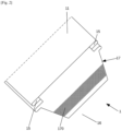
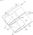
- An envelope 1 according to a first embodiment of the invention is shown in the figures 1 to 3 .
- Such an envelope 1 is made of a layer of flexible material such as paper and comprises a lower flap 12, an upper flap 11 superimposed on the lower flap 12, the flaps 11, 12 being made from the same sheet (M) of material folded along a transverse folding fold 13 perpendicular to lateral edges 14 of the flaps, towards an internal face 120.
- the envelope 1 comprises a hem 15 formed on each lateral edge 14, the flaps 11, 12 being connected to each other by lateral edges 14 by the fact that the hem 15 of the upper flap 11 is glued to the hem 15 of the lower flap 12 on sewing faces 150.
- An opening between the lateral edges 14 remains to allow the filling of the envelope 1.
- the upper 111 and lower 121 edges of the upper flap 11 and the lower flap 12 at the opening are offset from each other to leave a tab area 16 extending over the lower flap 12 between said edges.
- the envelope 1 further comprises a protective strip 17 extending over the tab area 16 on a layer of closing glue 170.
- the layer of closing glue 170 is intended to close the envelope 1 after removal of the protective strip 17 and folding of the tab area 16 onto the upper flap 11.
- the envelope 1 further comprises, along the opening, two pre-cut areas 19 capable of being detached from the envelope 1.
- the protective strip 17 and the closing adhesive layer 170 further extend over the pre-cut area 19.
- the pre-cut area 19 comprises a reinforced adhesive layer 171 covered by the protective strip 17 so that the protective strip 17 adheres more strongly to the reinforced adhesive layer 171 than to the closing adhesive layer 170.
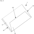
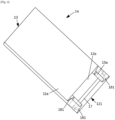
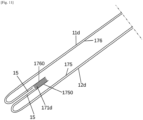
- the user of the envelope 1 wishes to use it, after having filled it, he successively grasps the pre-cut areas 19 by pinching the protective strip 17 and pulls to detach the pre-cut areas 19 from the envelope 1, then completely removes the protective strip 17.
- the layer of closing glue 170 on the tab area 16 then remains exposed, as shown in [ Fig.2 ].
- the user can then fold the tab area 16 by folding it over the upper flap 11 to close the envelope 1, as shown in [ Fig. 3 ].
- the envelope 1a is distinguished from that of the first embodiment in that the flaps 11a, 12a are connected to each other along the lateral edges 14a by two bellows 18, each bellows 18 comprising two cheeks 181.
- the central part, the cheek and the hem 15 form a sort of Z which is flattened during manufacture, but can be deployed when using the envelope 1.
- the cheeks 181 are connected together in the middle of the gusset 18 by gluing the hems on their sewing face 150.
- One of the hems is further glued to the cheek from which it originates, on the face opposite the sewing face 150.
- the pre-cut area 19 extends over the entire width of the cheek of the lower flap 12.
- the envelope 1b differs from that of the first embodiment in that it comprises at least two protective strips 17', 17" in parallel in a transverse direction, and at least one pre-cut zone 19', 19" for each protective strip 17', 17", as shown in figures 6 to 8 .
- the leg area 16b is provided with a transverse weakening line 160.
- the user removes the outermost protective strip 17', as shown in the [ Fig.7 ], and fold the tab area 16b over the upper flap 11b as shown in [ Fig.8 ].
- the closing glue layer 170' released by said protective strip 17' serves to glue the tab 16b.
- This envelope 1b can be opened by tearing the glued part along the weakening line 160, then closing the envelope 1b again by removing the second protective strip 17", to obtain a closure as in the [ Fig. 3 ].
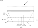
- the envelope 1c shown in the [ Fig.9 ] differs from that of the first embodiment in that the closing glue layer 170c is subdivided into a first, a second and a third part 1701, 1702, 1703 extending transversely.
- the lower flap 12c comprises in the tab area 16c a first and a second weakening line 161, 162, between the first and second part 1701, 1702, respectively the second and third part 1702, 1703.
- the protective strip 17 comprises a third weakening line 173 aligned with the first weakening line and a fourth weakening line 174 aligned with the second weakening line 162.
- the weakening lines 161, 162, 173, 174 extend through the pre-cut area 19c.
- a user When using such an envelope 1, a user inserts a content, not shown, into the envelope 1c through the opening, then detaches the third part of the protective strip 1703, including the pre-cut areas 19, by tearing it along the fourth weakening line 174, leaving the first and second parts 1701, 1702 of the protective strip 17. He folds the tab 16c down by folding it and presses the third part of the closing glue layer 1703 onto the upper flap 11 so as to obtain the bonding. The envelope 1 is then closed and can be sent.
- the recipient pulls on the assembly formed by the second part of the strip located between the weakening lines 161, 162 and the zone of corresponding tab 16 connected by the second part of glue 1702.
- the part which detaches forms a strap which separates the tab 16c into two parts, one of which remains stuck to the upper flap 11, and another which opens and releases the opening.
- Envelope 1c can be reused by the recipient. To do this, he removes the first part of the protective strip to release the remaining layer of closing glue 1701, he folds back the tab 16c as before to stick it on the upper flap 11.
- the envelope 1d differs from that of the first embodiment in that the protective strip 17d and the closing glue layer 170d are covered at least in part by the upper flap 11, in this case they extend over the entire periphery of the opening, as shown in figures 10 And 11
- the protective strip 17d is made of two parts 175, 176 glued together by a glue stronger than that of the closing glue layer 170 in a joining zone 177.
- This joining zone 177 is located on sections 1750, 1760 of the protective strip 17 which extend beyond the hems 15d and in an area where the flaps 11d, 12d overlap.
- the user grasps the corner of the tab area 16 to detach the pre-cut areas 19d by first driving the portion of the protective strip 175 onto the lower flap 12 and then the portion 176 onto the upper flap 11. He can then squeeze the flaps 11d, 12d together to stick them together at the opening and further fold the tab area 16d onto the upper flap 11 to stick it.
- the upper flap 11 and the lower flap 12 are made from the same sheet (M) formed into a casing and glued edge to edge and flattened.
- the envelope 1e is closed by a tab 127 coming from the lower flap folded down and glued onto the upper flap 11e, in a manner known per se.
- the upper edge 111e of the upper flap 11e along the opening extends beyond the lower flap 12e, the pre-cut area 19e extending over the entire width of the upper flap 11e set back from the lower edge 121e of the lower flap 12e up to a pre-cut line 191e.
- the pre-cut line 191e extends across the entire width of the upper flap 11e set back from the lower edge, as well as across the lower flap 12e joining the lower edge 121e by a slanted line 192e along each side edge 14e.
- the protective strip 17e extends across the lower flap 12e between the lower edge 121e and the portion of the pre-cut line 191e on the upper flap 11 also covering the slanted lines 192e.
- the envelope 1f differs from that of the sixth embodiment in that the lower and upper edges 111f, 121f are superimposed.
- the bottom is formed by known means, not detailed here, making it possible to produce a welded flat bottom, a square bottom or a hexagonal bottom etc.
- a ninth pre-cut segment 199 extends transversely on the upper flap 11f and two eighth segments extend from the ends of the ninth segment towards the edge 121f of the lower flap 12f.
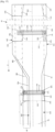
- the deposition means 23 comprise second unwinding means 230 for unwinding a sheet of protective material having a face coated with a non-stick coating, a cutting station 231 for forming the protective strips 17 from the sheet of protective material and a deposition roller 232 for bringing the protective strip onto the sheet M with the non-stick face on the glue zones.
- the deposition means 23 further comprise gluing means 233 for depositing the glue zones 170, 171 upstream of the deposition roller 232.
- the call means 24 are produced by a pair of counter-rotating rollers 241 driven by a motor, not shown.
- the application means 27 are, for example, nozzles injecting glue intermittently.
- the first cutting means 28, the folding means 29 and the stacking means 290 are conventional and are not detailed here.
- the various members are driven in rotation either by the same motor and synchronous mechanical transmissions, such as toothed belts or gears, or by several individual but electronically synchronized motors, or a combination of the two solutions.
- a machine 2' according to a second embodiment, shown in the [ Fig. 16 ], is intended to produce envelopes with gussets 18. It differs from that of the first embodiment in that a cheek forming station 30 is also provided downstream of the call means 24 and configured to further form a cheek 181 at each edge M1, M2 of the sheet M.
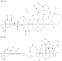
- Fig. 17 schematically shows the sheet M of flexible material when it is in the machine, being unwound from the right of the figure towards the cutting means to the left.
- the lower part of the figure, below a center line M3, represents one half of the sheet M during the formation of an envelope 1 without gussets according to the first embodiment, the other half being symmetrical with respect to the center line M3.
- the upper part represents half of the sheet M during the formation of an envelope 1 with gussets 18, according to the second embodiment of the envelope 1, the other half being symmetrical with respect to the center line M3.
- the sheet M of material is shown flat.
- a longitudinal line in dashed and double dot represents the future hem fold 151 or also, for the upper part of the figure, the future fold of the cheek 182.
- a transverse line 113 in dotted lines represents the position of the first edge 111 when the first flap 11 will be folded.
- a transverse line 123 in dashed and double dot represents the future transverse section separating a section of the sheet M.
- the pre-cut lines comprise a first segment 191 extending transversely at the future first edge 113 from the edge of the sheet M to the future fold of the hem 151 and a second segment 192 connected to the first segment 191 and extending obliquely to the future transverse cut 123.
- the segments are made symmetrically with respect to the center line M3.
- Closure glue 170 is deposited by creating a layer of closure glue 170 partially covering the second segments 192 between the future hem folds 151 and reinforced glue 171 is deposited as an extension of the closure glue 170 on the future hem 15.
- the protective strip 17 is deposited by extending transversely and completely covering the glue zones 170, 171.
- the formation of the hem 15 is shown by folding the selvage M1 of the sheet M along the longitudinal hem fold 151.
- the end of the protective strip 17 is thus also folded back at the same time as the hem 15.
- the hem is previously coated with glue at intervals by application means of the hemmer. The coating is done over a length corresponding to that of the upper flap. After the hem has been formed, it is glued to the upper flap.
- a line of three dashes and two dots represents the folding fold 13 between the upper flap 11, not shown, and the lower flap 12 onto which the upper flap 11 will be folded down by bringing the upper edge into alignment with the dotted line 113.
- the hem 15 has a sewing face 150 which is glued, so that after folding, the hem 15 along the upper flap 11 is glued to the hem 15 along the lower flap 12.
- the sheet M is cut, generally before folding, to detach a section T which will form the envelope 1 according to the first embodiment after folding and gluing the hems 15.
- the strip of material for manufacturing the protective strips has one side coated with a release layer over a width corresponding to that of the closing adhesive layer, the edges of the strip of material remaining raw.
- the areas of reinforced adhesive receive the same adhesive as the closing adhesive areas and the parts of the protective strip which do not have a release layer. The bond thus obtained in the areas of reinforced adhesive is stronger than on the areas of closing adhesive, which is the desired objective.
- the protective strip extends only between the future hem folds 151, leaving exposed the layer of glue 171 which extends over the pre-cut areas 19.
- the cheek or hem is folded over the back of the protective strip 17, they stick strongly together.
- the pre-cut areas are detached, they will pull the protective strip to expose the closing layer of glue 170.
- the pre-cut lines comprise a third segment 193 extending transversely at the future first edge from the edge of the sheet M to the future fold of the cheek 182 and a fourth segment 194 connected to the first segment 191 and extending obliquely to the future cutting line.
- Closure glue is deposited by creating a layer of closure glue 170 partially covering the fourth segments 194 between the future cheek folds 182 and reinforced glue 171 is deposited as an extension of the closure glue 170 on the future cheek 181.
- the protective strip 17a is deposited by extending transversely and completely covering the glue areas.
- the formation of the cheek 181 and the hem 15a is shown by longitudinally folding the edge of the sheet M2 according to a Z profile along the cheek fold 182 and the hem fold 151.
- the end of the protective strip 17a is thus also folded in at the same time as the cheek 181.
- a line of three dashes and two dots represents the folding fold 13 between the upper flap 11a, not shown, and the lower flap 12a onto which the upper flap 11a will be folded down by bringing the upper edge into alignment with the dotted line.
- the hem 15a has a sewing face 150 which is glued, so that after folding, the hem 15a along the upper flap 11a is glued to the hem 15a along the lower flap 12a.
- the sheet M is cut, generally before folding, to detach a section which will form the envelope 1 according to the second embodiment after folding and gluing the hems 15a.
- the manufacture of an envelope 1b according to the third embodiment has been shown, in the lower part, and a variant with gussets 18 in the upper part, not previously described.
- the pre-cut lines are similar to those of the [ Fig. 17 ], but completed by a fifth segment 195 extending transversely from the edge to the second segment 192 between the future first edge 113 and the future cutting line 123.
- closing glue 170b' and reinforced glue 171b' are deposited on the tab 16b extending over the pre-cut zone 19b' delimited between the first and fifth segments 191, 195, as well as the second protective strip 17b' parallel to the first protective strip 17b.
- a weakening line 160 is made at the same time as the pre-cut lines and extends between the fifth segments 195. The remainder of the formation of the envelope 1 is similar to the example described in relation to the [ Fig. 17 ].
- the protective strip 17b is in one piece and covers the two glue zones 170b, 170b'.
- the weakening line 160 and the fifth segments are produced together at the same time as a weakening line of the protective strip 17b superimposed on the weakening line 160, after the protective strip 17b has been deposited on the sheet M.
- the pre-cut zones 19c are identical to those of the [ Fig. 17 ].
- the closing adhesive layer 170 is subdivided into a first, a second and a third part 1701, 1702, 1703 extending transversely and parallel to each other.
- the protective strip 17 is deposited on the tab 16c on all the parts of the adhesive layer 1701, 1702, 1703. Then, weakening lines are produced, for example by in-line perforations.
- the first and second weakening lines 161, 162 are produced together between the first and second parts 1701, 1702, respectively the second and third part 1702, 1703.
- the third weakening line 173 aligned with the first weakening line 161 and the fourth weakening line 174 aligned with the second weakening line 162 are produced together.
- the weakening lines extend through the pre-cut area 19c.
- the weakening lines are produced after the protective strip has been removed, to mark the weakening lines on the tab area 16c and the protective strip 17c together. They can be produced upstream or downstream of the formation of the hems 15c and the cheeks 181c, or even after the flaps have been folded.
- the left part of the [ Fig. 18 ] is similar to that of the [ Fig. 17 ].
- the pre-cut zones 19 are identical to those of the [ Fig. 16 ].
- the closing adhesive layer 170d extends from hem 15 to hem 15, upstream of the cutting line 123 and downstream of the future upper edge 113.
- the protective strip 17d extends over the entire surface of the closing adhesive layer 170d and extends beyond the selvedges M1, M2.
- the left part of the figure represents the envelope 1 after cutting and after folding the upper flap 11d onto the lower flap 12d.
- the part of the protective strip 176 upstream of the cutting line remains on the upstream section, on the upper flap 11.
- the part of the protective strip 176 is found after folding inside the envelope 1 opposite the other part 175.
- the two parts of the protective strip 176, 175 are glued together by a reinforced glue 171d stronger than that of the closing glue layer 170 in a joining zone 177.
- This joining zone 177 is located on the panels 1760, 1750 of the parts 175, 176 of the protective strip 17d which extend beyond the hems 15 and in an area where the flaps 11d, 12d overlap. It was possible to deposit two zones of reinforced glue 171d on the panels 1760, 1750 upstream of the folding so that these parts 176, 175 stick together when they come together at the time of folding.
- Fig. 21 represents the manufacture of envelopes 1e according to the sixth embodiment.
- the figure represents in the lower part the manufacture of an envelope 1e with one side without gussets and in the upper part, above a center line M3, an envelope 1e with one side with a gusset 18.
- the envelope 1e will have no gussets or will be provided with gussets 18 on both sides.
- the sheet M of flexible material is first unrolled and provided with perforation lines, as shown on the right of the [ Fig. 21 ]. These perforation lines comprise a central line 124 extending in the transverse direction and located between future folds of the sides 141 of the envelope 1.
- the perforation lines further comprise a bottom line 125 also transverse and extending upstream of the central line 124, on either side of the ends thereof, with an oblique joining line 126.
- Pre-cut lines 195 extend parallel to the bottom line 125, downstream of the central line 124, join the central line 124 by oblique pre-cut lines 196 and delimit with the bottom line pre-cut areas 19e.
- Closure glue is deposited by creating a layer of closure glue 170e partially covering the oblique pre-cut lines 196 between the future folds of the sides 141 and reinforced glue 171e is deposited as an extension of the closure glue 170e beyond the future folds of the sides 141.
- the protective strip 17e is deposited by extending transversely and completely covering the glue areas 170e and 171e.
- the middle part of the [ Fig.21 ] shows a phase of forming a casing in which the selvedges M1, M2 are folded over the central zone of the sheet along the folds of the sides 141.
- the folded parts overlap each other and this overlapping part first receives glue, not shown, to form the upper flap 11.
- the upper part of the figure also shows the formation of a bellows 18, in a manner known per se which is not detailed here.
- a tearing station acting as a separation means which makes it possible to separate a section at the front of the casing.
- This type of station is conventional and is not detailed here. It is however specified that the casing is pinched on the one hand above the protective strip 17 and on the other hand upstream of the bottom line 125 to exert traction in the axial direction and obtain the separation of the section along the bottom line 125 and the central line 124. This produces a front tab on the end of the casing which protrudes from the lower flap 12 towards the front. The section was provided with the same front tab in the previous cycle so that this tab is used to close the front end of the section and thus form the envelope 1e. An envelope 1e is obtained as shown in the [ Fig. 12 ].
- a casing is formed in a similar manner.
- the sheet M of flexible material is first unrolled and provided with pre-cut lines, as shown on the right of the [ Fig. 22 ].
- a future cutting line 123f is represented with a two-point line and a dash along which the casing will be cut to separate a section.
- the pre-cut lines comprise an eighth segment 198 which extends along the future side fold from the cutting line downstream and a ninth segment 199 which extends transversely from the end of the eighth segment 198 to the edge M1, M2.
- the pre-cut areas 19f are delimited between the eighth, the ninth segment 198, 199 and the future cutting line 123f.
- Closure glue is deposited by creating a layer of closure glue 170f partially covering the eighth segments 198 and reinforced glue 171f is deposited as an extension of the closure glue 170f beyond the eighth segments.
- the protective strip 17f is deposited by extending transversely and completely covering the glue areas 170f, 171f.
- the formation of the casing is identical to the variant of the [ Fig.21 ].
- the casing After the casing has been formed, it passes into a cutting station 28 which separates a section at the front of the casing along the cutting line.
- the cut is a clean shear cut, although it could also be obtained by tearing as before.
- the formation of the bottom by folding means is not detailed.
- the pre-cut segments can be produced after the formation of the casing, upstream or downstream of the bottom formation, by a cutting station which, by enclosing several layers of material, allows all the layers to be cut except one, that of the lower flap. This produces the cutting of the fifth segment 195 or the ninth segment 199.
- the invention is not limited to the embodiments described by way of example, and is defined by the appended claims.
- Several protective strips can be adapted to the formation of the casings.
- the replacement of the bonding with reinforced glue can be replaced, as described in a variant of the first embodiment of the casing 1, by the use of protective strips without an anti-adhesive layer opposite the reinforced bonding areas and the same glue as for the closing glue areas.
Landscapes
- Engineering & Computer Science (AREA)
- Mechanical Engineering (AREA)
- Making Paper Articles (AREA)
Claims (22)
- Umschlag bestehend aus mindestens einem Blatt (M) aus flexiblem Material mit:- einer unteren Klappe (12),- einer auf die untere Klappe (12) aufgesetzten oberen Klappe (11), wobei diese Klappen (11, 12) durch seitliche Ränder (14) miteinander verbunden sind, zwischen denen (14) eine Öffnung verbleibt,- mindestens einem Schutzstreifen (17) auf einer Verschließ-Klebebeschichtung (170), die nach Abziehen des Schutzstreifens (17) zum Verschließen des Umschlags (1) dient.- entlang der Öffnung mindestens einem vorgestanzten Bereich (19), der sich vom Umschlag (1) lösen lässt, wobei sich die Verschließ-Klebebeschichtung (170) zumindest teilweise über den vorgestanzten Bereich (19) erstreckt,der dadurch gekennzeichnet ist, dass besagter Umschlag Verstärkungsmittel der Verbindung aufweist, welche den vorgestanzten Bereich (19) mit dem Schutzstreifen (17) in gegenüber der Verbindung zwischen Schutzstreifen (17) und Verschließ-Klebebeschichtung (170) verstärkter Weise verbinden.
- Umschlag gemäß Anspruch 1, in welchem die Verstärkungsmittel der Verbindung auf dem vorgestanzten Bereich (19) eine verstärkte Klebebeschichtung (171) aufweisen, die vom Schutzstreifen (17) bedeckt ist, der stärker an der verstärkten Klebebeschichtung (171) als an der Verschließ-Klebebeschichtung (170) haftet.
- Umschlag gemäß Anspruch 1, in dem der vorgestanzte Bereich auf einer Rückseite des Schutzstreifens (17) gefalzt ist, wobei die Verschließ-Klebebeschichtung (170) auf dem vorgestanzten Bereich (19) auf besagte Rückseite des Schutzstreifens (17) aufgeklebt ist und die Verstärkungsmittel der Verbindung von der Rückseite des Schutzstreifens (17) gebildet werden, die stärker als die der Rückseite gegenüberliegende Seite an der Verschließ-Klebebeschichtung (170) haftet.
- Umschlag gemäß einem der vorstehenden Ansprüche, in welchem die Klappen (11a, 12a) entlang der seitlichen Ränder (14) über Seitenfalten (18) verbunden sind, die (18) jeweils zwei Seitenteile (181) aufweisen.
- Umschlag gemäß Anspruch 4, in welchem der vorgestanzte Bereich (19a) sich mindestens über die ganze Länge der Seitenfalte (18) erstreckt.
- Umschlag gemäß einem der vorstehenden Ansprüche, der dadurch gekennzeichnet ist, dass er mindestens zwei in Querrichtung parallel zueinander geführte Schutzstreifen (17b, 17b') sowie zu jedem dieser Schutzstreifen (17b, 17b') mindestens einen vorgestanzten Bereich (19b, 19b') aufweist.
- Umschlag gemäß einem der vorstehenden Ansprüche, in welchem die Ränder (111, 121) der oberen (11) und der unteren (12) Klappe an der Öffnung gegeneinander versetzt sind, um Platz für einen Laschenbereich (16) zu schaffen, der sich über die untere Klappe (12) zwischen besagten Rändern (111, 121) erstreckt, während sich der Schutzstreifen (17) wiederum über den Laschenbereich (16) erstreckt.
- Umschlag gemäß Anspruch 7, in dem die Verschließ-Klebebeschichtung (170) in einen ersten, einen zweiten und einen dritten Abschnitt (1701, 1702, 1703) unterteilt ist, der sich jeweils in Querrichtung erstreckt, wobei die untere Klappe (12) zwischen dem ersten und dem zweiten Abschnitt (1701, 1702) bzw. dem zweiten und dem dritten Abschnitt (1702, 1703) eine erste bzw. zweite Schwächungslinie (161, 162) aufweist, wobei der Schutzstreifen (17c) eine dritte Schwächungslinie (173), die mit der ersten Schwächungslinie (161) fluchtet, sowie eine vierte Schwächungslinie (174), die mit der zweiten Schwächungslinie (162) fluchtet, aufweist, wobei sich diese Schwächungslinien (161, 162, 173, 174) quer über den vorgestanzten Bereich (19c) erstrecken.
- Umschlag gemäß einem der vorstehenden Ansprüche, in welchem der Schutzstreifen (17d) und die Verschließ-Klebebeschichtung (170d) zumindest teilweise von der oberen Klappe (11d) bedeckt werden.
- Umschlag gemäß Anspruch 9, in welchem der Schutzstreifen (17d) und die Verschließ-Klebebeschichtung (170d) sich über das gesamte Umfeld der Öffnung erstrecken.
- Umschlag gemäß einem der vorstehenden Ansprüche, in welchem die obere Klappe (11e, 11f) und die untere Klappe (12e, 12f) demselben schlauchförmigen und Kante an Kante (M1, M2) geklebten Blatt (M) entspringen.
- Umschlag gemäß Anspruch 11, in welchem die Ränder (123f) der Klappen (11f, 12f) entlang der Öffnung miteinander fluchten.
- Umschlag gemäß Anspruch 11, in welchem der Rand der oberen Klappe (11e) entlang der Öffnung über die untere Klappe (12e) hinausragt, wobei sich der vorgestanzte Bereich (19e) über die gesamte Breite der oberen Klappe (11e) unter dem Rand der unteren Klappe (121e) erstreckt.
- Umschlag gemäß einem der Ansprüche 1 bis 10, in dem die obere Klappe (11) und die untere Klappe (12) demselben Blatt (M) entlang eines quer verlaufenden Klappfalzes (13) gefalztem Material senkrecht zu den seitlichen Rändern (14) der Klappen in Richtung einer Innenseite (120) entspringen, wobei der Umschlag (1) einen an jedem seitlichen Rand (14) gebildeten Saum (15) aufweist, wobei der Saum (15) der oberen Klappe (11) mit dem Saum (15) der unteren Klappe (12) an den Nahtflächen (150) verklebt ist.
- Umschlag gemäß Anspruch 14, in welchem der Saum (15) auf die der Nahtfläche (150) gegenüberliegende Seite entlang lediglich eines der beiden Elemente obere Klappe (11) / untere Klappe (12) aufgeklebt ist.
- Umschlag gemäß einem der Ansprüche 14 bzw. 15, in welchem der Saum (15) mit einem mittleren Abschnitt der Klappe über ein auf diesem mittleren Abschnitt umgefalztes Seitenteil (181) dergestalt verbunden ist, dass eine Seitenfalte (18) von zwei Seitenteilen (181) gebildet wird, die über die miteinander verklebten Säume (15) untereinander verbunden sind.
- Verfahren zur Fertigung eines Umschlags, dem zufolge:- mindestens ein fortlaufender Streifen aus flexiblem bahnförmigem Blattmaterial (M) in eine Längsrichtung ausgerollt wird,- Vorstanzlinien (191, 192, 193, 194) eingeprägt werden, die auf dem Band vorgestanzte Bereiche (19) begrenzen;- eine Verschließ-Klebebeschichtung (170) aufgetragen wird, die sich beiderseits der Vorstanzlinien (192, 194) erstreckt; und ein Schutzstreifen (17) aufgegeben wird, der die Verschließ-Klebebeschichtung (170) zumindest außerhalb der vorgestanzten Bereiche (19) dergestalt verbindet, dass ein vorgestanzter Bereich (19) mit dem Schutzstreifen (17) in gegenüber der Verbindung zwischen Schutzstreifen (17) und Verschließ-Klebebeschichtung (170) verstärkter Weise verbunden ist,- der Streifen abschnittweise getrennt wird, wobei jeder Abschnitt so geschlossen wird, dass dabei ein Umschlag (1) gemäß einem der vorstehenden Ansprüche mit einer Öffnung entsteht, die von den vorgestanzten Bereichen (19) gesäumt wird.
- Verfahren zur Fertigung eines Umschlags gemäß Anspruch 17, dem zufolge:- mit einem Säumer an jeder Kante (M1, M2) vor dem Falzvorgang ein Saum (15) gebildet und die Säume (15) über eine Länge, die mindestens derjenigen einer oberen oder unteren Klappe (11, 12) entspricht, auf einer Nahtfläche (150) mit Klebstoff beschichtet wird,- mit Falzvorrichtungen (29) eine Falzung des Streifens entlang eines quer verlaufenden Klappfalzes (13) gebildet wird, um die obere Klappe (11) an die untere Klappe (12) gegen eine Innenseite (120) des Streifens anzulegen, wobei die Falzvorrichtungen (29) zu jeder Kante (M1, M2) Saum (15) an Saum (15) durch die Nahtfläche (150) dergestalt zurückgeführt werden, dass eine Verklebung der Säume (15) untereinander erzielt wird, um die obere Klappe (11) und die untere Klappe (12) entlang der Kanten (M1, M2) zu vereinen,- das Blatt in Form eines Querschnitts geschnitten wird, der von einem Querschneider (28) dergestalt vollzogen wird, dass vor oder nach der Falzung der Klappen (11, 12) übereinander ein Abschnitt hergestellt wird, der am Ende des Vorgangs den Umschlag (1) bildet.
- Verfahren gemäß Anspruch 18, dem zufolge der Querschnitt sich über den Schutzstreifen (17d) dergestalt erstreckt, dass dabei das Schutzband (17d) in einem ersten Abschnitt (176) von der oberen Klappe (11d) und in einem zweiten Abschnitt (176) von der unteren Klappe (12d) getrennt wird, wobei der erste und der zweite Abschnitt (175, 176) nach dem Falzvorgang zumindest teilweise übereinanderliegen.
- Verfahren gemäß einem der Ansprüche 17 bis 19, dem zufolge, zur Schaffung eines Umschlags (1c) gemäß Anspruch 8, die erste und die dritte Schwächungslinie (161, 173) bzw. die zweite und die vierte Schwächungslinie (162, 174), nach der Aufbringung des Schutzstreifens (17) auf das Blatt (M) jeweils gemeinsam eingeprägt werden.
- Verfahren gemäß einem der Ansprüche 17 bis 19, zur Herstellung eines Umschlags (1) gemäß Anspruch 13, dem zufolge auf dem Streifen quer verlaufende Perforationslinien, die ein hinteres Ende eines ersten Umschlags (1e) begrenzen, und eine vordere Lasche (127) eines dem ersten folgenden zweiten Umschlags (1e) zwischen einer Mittellinie (124) in Querrichtung und einer Grundlinie (125), von der die vordere Lasche (127) nach vorne überragt, geschaffen werden, wobei die Grundlinie (125) überdies den vorgestanzten Bereich (19e) begrenzt; das Blatt (M) schlauchförmig gebildet wird; sodann zur Trennung vom ersten und zweiten Umschlag (1e) durch eine axial auf den Schlauch wirkende Zugkraft geschritten wird, indem der erste Umschlag (1) auf die vorgestanzten Bereiche (19e) gepresst wird, damit die Trennung entlang der Mittellinie (124) und der Grundlinie (125) erfolgen kann.
- Maschine zur Fertigung flexibler Umschläge, die dadurch gekennzeichnet ist, dass sie die folgenden Elemente aufweist:- Abspulmittel (201) zum Abspulen mindestens eines Blatts (M) aus flexiblem bahnförmigem Blattmaterial (M) in Längsrichtung,- Einprägemittel (202) zum Einprägen von Vorstanzlinien zur Begrenzung der vorgestanzten Bereiche (19) auf dem Blatt,- Auftragungsmittel (23) zur Auftragung in regelmäßigen Abständen einer Verschließ-Klebebeschichtung (170, 171), die sich beiderseits der Vorstanzlinien auf dem Blatt (M) erstreckt, und einen Schutzstreifen (17), der die Verschließ-Klebebeschichtung mindestens außerhalb der vorgestanzten Bereiche (19) bedeckt,- Trennmittel (28) zum Trennen des Blatts (M) in Abschnitte (T) entlang eines hinteren Randes des Abschnitts,- Falzmittel (29) zum Verschließen jedes Abschnitts (T) zur Bildung eines Umschlags (1) gemäß einem der Ansprüche 1 bis 16, der eine Öffnung entlang des hinteren Randes aufweist, der an die vorgestanzten Bereiche (19) angrenzt;- wobei die Maschine so konfiguriert ist, dass diese das Verfahren gemäß einem der Ansprüche 17 bis 21 umsetzt.
Applications Claiming Priority (2)
| Application Number | Priority Date | Filing Date | Title |
|---|---|---|---|
| FR2105063A FR3122867B1 (fr) | 2021-05-12 | 2021-05-12 | Enveloppe avec patte de fermeture, procédé et machine de fabrication d’une telle enveloppe |
| PCT/EP2022/062442 WO2022238304A1 (fr) | 2021-05-12 | 2022-05-09 | Enveloppe avec patte de fermeture, procédé et machine de fabrication d'une telle enveloppe |
Publications (2)
| Publication Number | Publication Date |
|---|---|
| EP4337558A1 EP4337558A1 (de) | 2024-03-20 |
| EP4337558B1 true EP4337558B1 (de) | 2025-04-16 |
Family
ID=77317070
Family Applications (1)
| Application Number | Title | Priority Date | Filing Date |
|---|---|---|---|
| EP22727932.0A Active EP4337558B1 (de) | 2021-05-12 | 2022-05-09 | Umschlag, herstellungsverfahren und maschine |
Country Status (4)
| Country | Link |
|---|---|
| US (1) | US20250065590A1 (de) |
| EP (1) | EP4337558B1 (de) |
| FR (1) | FR3122867B1 (de) |
| WO (1) | WO2022238304A1 (de) |
Families Citing this family (1)
| Publication number | Priority date | Publication date | Assignee | Title |
|---|---|---|---|---|
| FR3113036B1 (fr) * | 2020-07-30 | 2022-07-01 | Holweg Group | Enveloppe réutilisable avec volet de fermeture prédécoupé, procédé et machine de fabrication d'une telle enveloppe |
Citations (1)
| Publication number | Priority date | Publication date | Assignee | Title |
|---|---|---|---|---|
| EP3564146A1 (de) * | 2018-05-02 | 2019-11-06 | J.B. Machines S.r.l. | Papiersack für archivierungszwecke und entsprechende verwendung eines solchen sackes |
Family Cites Families (15)
| Publication number | Priority date | Publication date | Assignee | Title |
|---|---|---|---|---|
| FR786579A (fr) | 1934-06-26 | 1935-09-05 | Holweg Const Mec | Procédé et dispositifs pour la fabrication de sacs plats |
| US2056132A (en) * | 1935-12-20 | 1936-09-29 | Old Colony Envelope Company | Envelope |
| US2118706A (en) * | 1937-06-14 | 1938-05-24 | Us Envelope Co | Dry-sealing envelope |
| US2998180A (en) * | 1959-03-25 | 1961-08-29 | Crown Zellerbach Corp | Self-sealing container |
| FR1270400A (fr) | 1960-10-13 | 1961-08-25 | Holweg Const Mec | Machine pour la fabrication en continu de sacs et sachets plats |
| US5044772A (en) * | 1987-04-28 | 1991-09-03 | Minnesota Mining And Manufacturing Company | Flexible bag with supporting and sealing tape |
| US4785940A (en) * | 1987-07-02 | 1988-11-22 | Minnesota Mining And Manufacturing Company | Flexible bag with a pressure sensitive adhesive closure strip |
| US4961503A (en) * | 1988-03-17 | 1990-10-09 | Kapak Corporation | Tamper evident notched sealing envelope |
| DE8901531U1 (de) * | 1989-02-10 | 1989-03-23 | AWA Couvert August Wegener GmbH + Co, 3220 Alfeld | Briefumschlag, vorzugsweise aus Recyclingpapier |
| US5002220A (en) * | 1989-10-18 | 1991-03-26 | Manufacturing Concepts, Inc. | Adhesive closure flap with protective liner and detachable tab |
| FR3030352B1 (fr) | 2014-12-19 | 2018-09-07 | Holweg Group | Procede et machine de fabrication de sacs |
| US10730678B2 (en) * | 2016-05-10 | 2020-08-04 | Sonoco Development, Inc. | Mono-web package with tamper-evident tear strip and resealable flap portion |
| US11167901B2 (en) * | 2017-06-05 | 2021-11-09 | Bemis Company, Inc. | Flexible resealable packages |
| KR101956556B1 (ko) * | 2018-06-22 | 2019-03-11 | 이용관 | 포장과 개봉이 용이한 합성수지 봉투 |
| MX2024002007A (es) * | 2021-09-02 | 2024-03-05 | Pac Worldwide Corp | Revestimiento de liberacion para paquetes de correo. |
-
2021
- 2021-05-12 FR FR2105063A patent/FR3122867B1/fr active Active
-
2022
- 2022-05-09 EP EP22727932.0A patent/EP4337558B1/de active Active
- 2022-05-09 US US18/560,245 patent/US20250065590A1/en active Pending
- 2022-05-09 WO PCT/EP2022/062442 patent/WO2022238304A1/fr not_active Ceased
Patent Citations (1)
| Publication number | Priority date | Publication date | Assignee | Title |
|---|---|---|---|---|
| EP3564146A1 (de) * | 2018-05-02 | 2019-11-06 | J.B. Machines S.r.l. | Papiersack für archivierungszwecke und entsprechende verwendung eines solchen sackes |
Also Published As
| Publication number | Publication date |
|---|---|
| US20250065590A1 (en) | 2025-02-27 |
| FR3122867B1 (fr) | 2023-05-12 |
| FR3122867A1 (fr) | 2022-11-18 |
| EP4337558A1 (de) | 2024-03-20 |
| WO2022238304A1 (fr) | 2022-11-17 |
Similar Documents
| Publication | Publication Date | Title |
|---|---|---|
| EP1226929B1 (de) | Verfahren und Maschine zur Herstellung von Seitenfaltbeutel mit Reissverschluss | |
| EP1458627B1 (de) | Verpackung, wie zum beispiel beutel, mit ausgerichteter aufreissöffnung | |
| FR2769288A1 (fr) | Procede de fabrication automatique de sachets, machine a cet effet et sachets obtenus | |
| EP2864114B1 (de) | Maschine zur herstellung von tüten mit flachen böden | |
| FR3030352A1 (fr) | Procede et machine de fabrication de sacs | |
| EP4337558B1 (de) | Umschlag, herstellungsverfahren und maschine | |
| EP1474285B9 (de) | Doppelfaltiger beutel | |
| EP0667288B1 (de) | Vorrichtung und Verfahren zum Verpacken von Produkten in hermetischen, wiederverschliessbaren Verpackungen | |
| EP4337458A1 (de) | Verfahren und vorrichtung zur herstellung eines flexiblen, insbesondere mit verstärkung versehenen beutels in form einer hülle | |
| EP4188819B1 (de) | Wiederverwendbarer briefumschlag mit vorgeschnittener verschlussklappe, verfahren und maschine zur herstellung eines solchen umschlags | |
| EP3894204B1 (de) | Verfahren und maschine zur formung von flexiblen beuteln mit spezialboden | |
| EP3710242B1 (de) | Verfahren und maschine zur herstellung eines stapels von beuteln | |
| EP2076378A2 (de) | Verfahren zur herstellung eines verpackungsbeutels und auf diese weise hergestellter verpackungsbeutel | |
| EP4337457A1 (de) | Flexibler beutel mit umwandelbarem boden, verfahren und maschine zur herstellung davon | |
| FR2826606A1 (fr) | Procede de reunion de sachets, dispositif pour la mise en oeuvre du procede et chaine de sachets ainsi que chaine de sachets empiles | |
| EP3328628B1 (de) | Maschine und verfahren zur herstellung von beuteln | |
| BE528759A (de) | ||
| BE513094A (de) | ||
| BE363705A (de) | ||
| BE427049A (de) | ||
| BE516766A (de) |
Legal Events
| Date | Code | Title | Description |
|---|---|---|---|
| STAA | Information on the status of an ep patent application or granted ep patent |
Free format text: STATUS: UNKNOWN |
|
| STAA | Information on the status of an ep patent application or granted ep patent |
Free format text: STATUS: THE INTERNATIONAL PUBLICATION HAS BEEN MADE |
|
| PUAI | Public reference made under article 153(3) epc to a published international application that has entered the european phase |
Free format text: ORIGINAL CODE: 0009012 |
|
| STAA | Information on the status of an ep patent application or granted ep patent |
Free format text: STATUS: REQUEST FOR EXAMINATION WAS MADE |
|
| 17P | Request for examination filed |
Effective date: 20231205 |
|
| AK | Designated contracting states |
Kind code of ref document: A1 Designated state(s): AL AT BE BG CH CY CZ DE DK EE ES FI FR GB GR HR HU IE IS IT LI LT LU LV MC MK MT NL NO PL PT RO RS SE SI SK SM TR |
|
| DAV | Request for validation of the european patent (deleted) | ||
| DAX | Request for extension of the european patent (deleted) | ||
| GRAP | Despatch of communication of intention to grant a patent |
Free format text: ORIGINAL CODE: EPIDOSNIGR1 |
|
| STAA | Information on the status of an ep patent application or granted ep patent |
Free format text: STATUS: GRANT OF PATENT IS INTENDED |
|
| RIC1 | Information provided on ipc code assigned before grant |
Ipc: B31B 160/20 20170101ALI20241104BHEP Ipc: B31B 155/00 20170101ALI20241104BHEP Ipc: B31B 70/81 20170101ALI20241104BHEP Ipc: B31B 70/62 20170101ALI20241104BHEP Ipc: B31B 70/10 20170101ALI20241104BHEP Ipc: B65D 33/18 20060101ALI20241104BHEP Ipc: B65D 30/20 20060101ALI20241104BHEP Ipc: B65D 27/38 20060101ALI20241104BHEP Ipc: B65D 27/06 20060101ALI20241104BHEP Ipc: B65D 27/34 20060101ALI20241104BHEP Ipc: B65D 27/14 20060101AFI20241104BHEP |
|
| INTG | Intention to grant announced |
Effective date: 20241121 |
|
| GRAS | Grant fee paid |
Free format text: ORIGINAL CODE: EPIDOSNIGR3 |
|
| GRAA | (expected) grant |
Free format text: ORIGINAL CODE: 0009210 |
|
| STAA | Information on the status of an ep patent application or granted ep patent |
Free format text: STATUS: THE PATENT HAS BEEN GRANTED |
|
| AK | Designated contracting states |
Kind code of ref document: B1 Designated state(s): AL AT BE BG CH CY CZ DE DK EE ES FI FR GB GR HR HU IE IS IT LI LT LU LV MC MK MT NL NO PL PT RO RS SE SI SK SM TR |
|
| REG | Reference to a national code |
Ref country code: GB Ref legal event code: FG4D Free format text: NOT ENGLISH |
|
| REG | Reference to a national code |
Ref country code: CH Ref legal event code: EP Ref country code: DE Ref legal event code: R096 Ref document number: 602022013275 Country of ref document: DE |
|
| REG | Reference to a national code |
Ref country code: IE Ref legal event code: FG4D Free format text: LANGUAGE OF EP DOCUMENT: FRENCH |
|
| PGFP | Annual fee paid to national office [announced via postgrant information from national office to epo] |
Ref country code: DE Payment date: 20250521 Year of fee payment: 4 |
|
| PGFP | Annual fee paid to national office [announced via postgrant information from national office to epo] |
Ref country code: FR Payment date: 20250514 Year of fee payment: 4 |
|
| PGFP | Annual fee paid to national office [announced via postgrant information from national office to epo] |
Ref country code: AT Payment date: 20250721 Year of fee payment: 4 |
|
| REG | Reference to a national code |
Ref country code: NL Ref legal event code: MP Effective date: 20250416 |
|
| PG25 | Lapsed in a contracting state [announced via postgrant information from national office to epo] |
Ref country code: NL Free format text: LAPSE BECAUSE OF FAILURE TO SUBMIT A TRANSLATION OF THE DESCRIPTION OR TO PAY THE FEE WITHIN THE PRESCRIBED TIME-LIMIT Effective date: 20250416 |
|
| REG | Reference to a national code |
Ref country code: AT Ref legal event code: MK05 Ref document number: 1785507 Country of ref document: AT Kind code of ref document: T Effective date: 20250416 |
|
| PG25 | Lapsed in a contracting state [announced via postgrant information from national office to epo] |
Ref country code: FI Free format text: LAPSE BECAUSE OF FAILURE TO SUBMIT A TRANSLATION OF THE DESCRIPTION OR TO PAY THE FEE WITHIN THE PRESCRIBED TIME-LIMIT Effective date: 20250416 Ref country code: PT Free format text: LAPSE BECAUSE OF FAILURE TO SUBMIT A TRANSLATION OF THE DESCRIPTION OR TO PAY THE FEE WITHIN THE PRESCRIBED TIME-LIMIT Effective date: 20250818 Ref country code: ES Free format text: LAPSE BECAUSE OF FAILURE TO SUBMIT A TRANSLATION OF THE DESCRIPTION OR TO PAY THE FEE WITHIN THE PRESCRIBED TIME-LIMIT Effective date: 20250416 |
|
| REG | Reference to a national code |
Ref country code: LT Ref legal event code: MG9D |
|
| PG25 | Lapsed in a contracting state [announced via postgrant information from national office to epo] |
Ref country code: NO Free format text: LAPSE BECAUSE OF FAILURE TO SUBMIT A TRANSLATION OF THE DESCRIPTION OR TO PAY THE FEE WITHIN THE PRESCRIBED TIME-LIMIT Effective date: 20250716 Ref country code: GR Free format text: LAPSE BECAUSE OF FAILURE TO SUBMIT A TRANSLATION OF THE DESCRIPTION OR TO PAY THE FEE WITHIN THE PRESCRIBED TIME-LIMIT Effective date: 20250717 |
|
| PG25 | Lapsed in a contracting state [announced via postgrant information from national office to epo] |
Ref country code: PL Free format text: LAPSE BECAUSE OF FAILURE TO SUBMIT A TRANSLATION OF THE DESCRIPTION OR TO PAY THE FEE WITHIN THE PRESCRIBED TIME-LIMIT Effective date: 20250416 |
|
| PG25 | Lapsed in a contracting state [announced via postgrant information from national office to epo] |
Ref country code: BG Free format text: LAPSE BECAUSE OF FAILURE TO SUBMIT A TRANSLATION OF THE DESCRIPTION OR TO PAY THE FEE WITHIN THE PRESCRIBED TIME-LIMIT Effective date: 20250416 |
|
| PG25 | Lapsed in a contracting state [announced via postgrant information from national office to epo] |
Ref country code: HR Free format text: LAPSE BECAUSE OF FAILURE TO SUBMIT A TRANSLATION OF THE DESCRIPTION OR TO PAY THE FEE WITHIN THE PRESCRIBED TIME-LIMIT Effective date: 20250416 Ref country code: AT Free format text: LAPSE BECAUSE OF FAILURE TO SUBMIT A TRANSLATION OF THE DESCRIPTION OR TO PAY THE FEE WITHIN THE PRESCRIBED TIME-LIMIT Effective date: 20250416 |
|
| PG25 | Lapsed in a contracting state [announced via postgrant information from national office to epo] |
Ref country code: RS Free format text: LAPSE BECAUSE OF FAILURE TO SUBMIT A TRANSLATION OF THE DESCRIPTION OR TO PAY THE FEE WITHIN THE PRESCRIBED TIME-LIMIT Effective date: 20250716 |
|
| PG25 | Lapsed in a contracting state [announced via postgrant information from national office to epo] |
Ref country code: IS Free format text: LAPSE BECAUSE OF FAILURE TO SUBMIT A TRANSLATION OF THE DESCRIPTION OR TO PAY THE FEE WITHIN THE PRESCRIBED TIME-LIMIT Effective date: 20250816 |
|
| PG25 | Lapsed in a contracting state [announced via postgrant information from national office to epo] |
Ref country code: LV Free format text: LAPSE BECAUSE OF FAILURE TO SUBMIT A TRANSLATION OF THE DESCRIPTION OR TO PAY THE FEE WITHIN THE PRESCRIBED TIME-LIMIT Effective date: 20250416 |
|
| REG | Reference to a national code |
Ref country code: CH Ref legal event code: H13 Free format text: ST27 STATUS EVENT CODE: U-0-0-H10-H13 (AS PROVIDED BY THE NATIONAL OFFICE) Effective date: 20251223 |
|
| PG25 | Lapsed in a contracting state [announced via postgrant information from national office to epo] |
Ref country code: SM Free format text: LAPSE BECAUSE OF FAILURE TO SUBMIT A TRANSLATION OF THE DESCRIPTION OR TO PAY THE FEE WITHIN THE PRESCRIBED TIME-LIMIT Effective date: 20250416 Ref country code: DK Free format text: LAPSE BECAUSE OF FAILURE TO SUBMIT A TRANSLATION OF THE DESCRIPTION OR TO PAY THE FEE WITHIN THE PRESCRIBED TIME-LIMIT Effective date: 20250416 |
|
| PG25 | Lapsed in a contracting state [announced via postgrant information from national office to epo] |
Ref country code: LU Free format text: LAPSE BECAUSE OF NON-PAYMENT OF DUE FEES Effective date: 20250509 |
|
| PG25 | Lapsed in a contracting state [announced via postgrant information from national office to epo] |
Ref country code: CH Free format text: LAPSE BECAUSE OF NON-PAYMENT OF DUE FEES Effective date: 20250531 |
|
| REG | Reference to a national code |
Ref country code: DE Ref legal event code: R097 Ref document number: 602022013275 Country of ref document: DE |
|
| PG25 | Lapsed in a contracting state [announced via postgrant information from national office to epo] |
Ref country code: CZ Free format text: LAPSE BECAUSE OF FAILURE TO SUBMIT A TRANSLATION OF THE DESCRIPTION OR TO PAY THE FEE WITHIN THE PRESCRIBED TIME-LIMIT Effective date: 20250416 |
|
| PG25 | Lapsed in a contracting state [announced via postgrant information from national office to epo] |
Ref country code: EE Free format text: LAPSE BECAUSE OF FAILURE TO SUBMIT A TRANSLATION OF THE DESCRIPTION OR TO PAY THE FEE WITHIN THE PRESCRIBED TIME-LIMIT Effective date: 20250416 |
|
| PG25 | Lapsed in a contracting state [announced via postgrant information from national office to epo] |
Ref country code: SK Free format text: LAPSE BECAUSE OF FAILURE TO SUBMIT A TRANSLATION OF THE DESCRIPTION OR TO PAY THE FEE WITHIN THE PRESCRIBED TIME-LIMIT Effective date: 20250416 |
|
| PG25 | Lapsed in a contracting state [announced via postgrant information from national office to epo] |
Ref country code: IT Free format text: LAPSE BECAUSE OF FAILURE TO SUBMIT A TRANSLATION OF THE DESCRIPTION OR TO PAY THE FEE WITHIN THE PRESCRIBED TIME-LIMIT Effective date: 20250416 |
|
| REG | Reference to a national code |
Ref country code: BE Ref legal event code: MM Effective date: 20250531 |
|
| PG25 | Lapsed in a contracting state [announced via postgrant information from national office to epo] |
Ref country code: MC Free format text: LAPSE BECAUSE OF FAILURE TO SUBMIT A TRANSLATION OF THE DESCRIPTION OR TO PAY THE FEE WITHIN THE PRESCRIBED TIME-LIMIT Effective date: 20250416 |
|
| PLBE | No opposition filed within time limit |
Free format text: ORIGINAL CODE: 0009261 |
|
| STAA | Information on the status of an ep patent application or granted ep patent |
Free format text: STATUS: NO OPPOSITION FILED WITHIN TIME LIMIT |
|
| REG | Reference to a national code |
Ref country code: CH Ref legal event code: L10 Free format text: ST27 STATUS EVENT CODE: U-0-0-L10-L00 (AS PROVIDED BY THE NATIONAL OFFICE) Effective date: 20260225 |
|
| PG25 | Lapsed in a contracting state [announced via postgrant information from national office to epo] |
Ref country code: RO Free format text: LAPSE BECAUSE OF FAILURE TO SUBMIT A TRANSLATION OF THE DESCRIPTION OR TO PAY THE FEE WITHIN THE PRESCRIBED TIME-LIMIT Effective date: 20250416 |
|
| 26N | No opposition filed |
Effective date: 20260119 |