EP4337068B1 - Maschine zum kochen von lebensmitteln in einem behälter - Google Patents
Maschine zum kochen von lebensmitteln in einem behälter Download PDFInfo
- Publication number
- EP4337068B1 EP4337068B1 EP22727989.0A EP22727989A EP4337068B1 EP 4337068 B1 EP4337068 B1 EP 4337068B1 EP 22727989 A EP22727989 A EP 22727989A EP 4337068 B1 EP4337068 B1 EP 4337068B1
- Authority
- EP
- European Patent Office
- Prior art keywords
- support
- machine
- container
- dispenser
- plate
- Prior art date
- Legal status (The legal status is an assumption and is not a legal conclusion. Google has not performed a legal analysis and makes no representation as to the accuracy of the status listed.)
- Active
Links
Images
Classifications
-
- A—HUMAN NECESSITIES
- A47—FURNITURE; DOMESTIC ARTICLES OR APPLIANCES; COFFEE MILLS; SPICE MILLS; SUCTION CLEANERS IN GENERAL
- A47J—KITCHEN EQUIPMENT; COFFEE MILLS; SPICE MILLS; APPARATUS FOR MAKING BEVERAGES
- A47J27/00—Cooking-vessels
- A47J27/04—Cooking-vessels for cooking food in steam; Devices for extracting fruit juice by means of steam ; Vacuum cooking vessels
-
- A—HUMAN NECESSITIES
- A47—FURNITURE; DOMESTIC ARTICLES OR APPLIANCES; COFFEE MILLS; SPICE MILLS; SUCTION CLEANERS IN GENERAL
- A47J—KITCHEN EQUIPMENT; COFFEE MILLS; SPICE MILLS; APPARATUS FOR MAKING BEVERAGES
- A47J27/00—Cooking-vessels
- A47J27/10—Cooking-vessels with water-bath arrangements for domestic use
-
- A—HUMAN NECESSITIES
- A47—FURNITURE; DOMESTIC ARTICLES OR APPLIANCES; COFFEE MILLS; SPICE MILLS; SUCTION CLEANERS IN GENERAL
- A47J—KITCHEN EQUIPMENT; COFFEE MILLS; SPICE MILLS; APPARATUS FOR MAKING BEVERAGES
- A47J27/00—Cooking-vessels
- A47J27/14—Cooking-vessels for use in hotels, restaurants, or canteens
- A47J27/16—Cooking-vessels for use in hotels, restaurants, or canteens heated by steam
-
- A—HUMAN NECESSITIES
- A47—FURNITURE; DOMESTIC ARTICLES OR APPLIANCES; COFFEE MILLS; SPICE MILLS; SUCTION CLEANERS IN GENERAL
- A47J—KITCHEN EQUIPMENT; COFFEE MILLS; SPICE MILLS; APPARATUS FOR MAKING BEVERAGES
- A47J27/00—Cooking-vessels
- A47J27/14—Cooking-vessels for use in hotels, restaurants, or canteens
- A47J27/18—Cooking-vessels for use in hotels, restaurants, or canteens heated by water-bath, e.g. pasta-cookers
-
- A—HUMAN NECESSITIES
- A47—FURNITURE; DOMESTIC ARTICLES OR APPLIANCES; COFFEE MILLS; SPICE MILLS; SUCTION CLEANERS IN GENERAL
- A47J—KITCHEN EQUIPMENT; COFFEE MILLS; SPICE MILLS; APPARATUS FOR MAKING BEVERAGES
- A47J27/00—Cooking-vessels
- A47J2027/006—Cooking-vessels especially adapted for preparing pasta
-
- A—HUMAN NECESSITIES
- A47—FURNITURE; DOMESTIC ARTICLES OR APPLIANCES; COFFEE MILLS; SPICE MILLS; SUCTION CLEANERS IN GENERAL
- A47J—KITCHEN EQUIPMENT; COFFEE MILLS; SPICE MILLS; APPARATUS FOR MAKING BEVERAGES
- A47J27/00—Cooking-vessels
- A47J27/04—Cooking-vessels for cooking food in steam; Devices for extracting fruit juice by means of steam ; Vacuum cooking vessels
- A47J2027/043—Cooking-vessels for cooking food in steam; Devices for extracting fruit juice by means of steam ; Vacuum cooking vessels for cooking food in steam
Definitions
- the present invention relates to a machine for cooking food in a container.
- the present invention relates to a machine for cooking food by means of the supply of hot water and steam.
- Patent applications No. WO 2019/207509 , No. WO 2020/212909 , No. WO 2020/212207 and No. WO 2020/212904 of the applicant teach how to cook fresh food contained in a container by means of the supply of hot water and steam in the container containing the food.
- the object of the present invention is to provide a machine for cooking food that can easily and economically satisfy the needs set out above.
- a machine for cooking food in a container according to claim 1 is manufactured.
- the present invention it is possible to ensure a solid and stable coupling between the dispenser and the container during the cooking of the food and, at the same time, it is possible to decouple the container from the dispenser so as to allow the replacement of the container in a simple and fast way.
- the mechanism allows keeping the container pressed against the dispenser during the cooking process so as to prevent steam leakage from the container and separating the container from the dispenser, by operating the command unit, once the cooking process is finished.
- the support has a plurality of openings.
- the machine comprises a steam supply duct, which is in fluidic communication with the at least one first opening; and a hot water supply duct, which is in fluidic communication with the at least one second opening.
- the mechanism is configured to push the container against the dispenser so as to close an upper opening of the container and to form a substantially closed cooking compartment for cooking the food.
- the dispenser comprises a lid configured to close the container, so as to form the substantially closed cooking compartment together with the container.
- the support is movable in a direction substantially parallel to a longitudinal axis.
- the dispenser extends along the longitudinal axis from the plate towards the support in the space between the plate and the support.
- the dispenser is substantially aligned with the movement direction of the support.
- the mechanism comprises a crossbar, which is movable in a direction substantially parallel to the longitudinal axis and is connected to the kinematic assembly of the connecting rod-crank type; and at least one guide, which extends in a direction parallel to the longitudinal axis and is connected to the movable crossbar and the support.
- the kinematic assembly of the connecting rod-crank type comprises a shaft, which is rotatable about a transverse axis with respect to the longitudinal axis and is connected to the command unit; a crank body jointly coupled to the shaft; and a connecting rod body having a first end hinged to the crank body and a second end hinged to the movable crossbar.
- the rotation of the shaft determines the rotation of the crank body and, consequently, the movement of the connecting rod body. In this way, it is possible to determine the translation of the movable crossbar along the longitudinal axis.
- the elastic element is arranged between the movable crossbar and a blocking element fixed to the frame so as to counteract the movement of the movable crossbar towards the dispenser.
- the mechanism comprises two lateral guides arranged on opposite bands with respect to the dispenser; each lateral guide being a rod comprising a first end connected to the movable crossbar and a second end connected to the support so as to transmit the translatory motion from the movable crossbar to the support.
- the command unit comprises a hand lever so as to allow the support to be lowered manually.
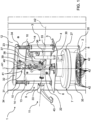
- reference numeral 1 indicates, as a whole, a machine for cooking food in a container 2 containing said food.
- the machine 1 can be used in public catering places (for example coffee bars, restaurants, diners etc.) or at home.
- the food contained in the container 2 can be a dose of raw pasta or a sauce for said dose of pasta.
- the machine 1 comprises a frame 3 comprising a plate 4 having an upper face 5 and a lower face 6; a dispenser 7 supported by the plate 4 along the lower face 6; a support 8 configured to be arranged below the container 2 and to support the container 2; and a mechanism 9 coupled to the plate 4 and to the support 8 and comprising at least one elastic element 10 for pushing the support 8 towards the dispenser 7; and a command unit 11 for counteracting the force of the elastic element 10 and lowering the support 8 with respect to the plate 4.
- the frame 3 further comprises a casing 12, within which a first boiler and a second boiler, not shown in the accompanying figures, are arranged for respectively supplying steam and hot water to the dispenser 7; and a bearing 13, which is fixed to the casing 12 above the plate 4 and is provided with two annular-shaped blocking elements 14.
- the dispenser 7 extends along a longitudinal axis A1 from the plate 4 towards the support 8 in the space between the plate 4 and the support 8.
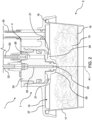
- the container 2 is configured to contain food 15 and comprises a base wall 16, preferably having a circular shape; a side wall 17, preferably slightly flared, provided with an upper edge 18; and an upper opening 19, preferably having a circular shape, opposite the base wall 16.
- the dispenser 7 comprises at least one opening 20 for dispensing steam into the container 2 and at least one opening 21 for dispensing hot water into the container 2.
- the machine 1 comprises a steam supply duct 22, which is in fluidic communication with the opening 20; and a hot water supply duct 23, which is in fluidic communication with the opening 21.
- the dispenser 7 comprises a central body 24 provided with a steam supply channel 25, which is in fluidic communication with the duct 22 and with the opening 20, and with a hot water supply channel 26, which is in fluidic communication with the duct 23 and with the openings 21; and a lid 27, which is arranged about the central body 24 and is configured to close the upper opening 19 of the container 2 so as to form a substantially closed cooking compartment for cooking the food 15.
- the central body 24 comprises a central protrusion 28, which is provided with the opening 20; and an annular wall 29, which extends about the central protrusion 28 and is provided with a plurality of openings 21.
- the machine 1 further comprises a steam evacuation duct 30, which is configured to evacuate steam from the container 2 and is connected to a steam discharge, not shown in the accompanying figures.
- the duct 30 extends through the lid 27 so as to put the inside of the cooking compartment into fluidic communication with the steam discharge.
- the mechanism 9 is configured to push the container 2 against the dispenser 7 so as to close the upper opening 19 of the container 2 and to form the substantially closed cooking compartment.
- the mechanism 9 comprises a kinematic assembly 31 of the connecting rod-crank type configured to convert a rotary motion given to the command unit 11 into a translatory motion of the support 8.
- the mechanism 9 comprises a crossbar 32, which is movable in a direction substantially parallel to the longitudinal axis A1 and is connected to the kinematic assembly 31; and at least one guide 33, which extends in a direction parallel to the longitudinal axis A1 and is connected to the crossbar 32 and the support 8.
- the mechanism 9 comprises two lateral guides 33 arranged on opposite bands with respect to the dispenser 7.
- Each guide 33 extends through a respective opening of the plate 4 and inside the respective blocking element 14.
- each guide 33 is a rod comprising an end 34 connected to the movable crossbar 32 and an end 35 connected to the support 8.
- the crossbar 32 faces the upper face 5 of the plate 4 and extends in a direction substantially transverse with respect to the longitudinal axis A1.
- the mechanism 9 comprises two elastic elements 10, each of which is arranged between the crossbar 32 and the respective blocking element 14 so as to counteract the movement of the crossbar 32 towards the dispenser 7.
- each elastic element 10 is a coil spring arranged about the respective guide 33.
- the kinematic assembly 31 comprises a shaft 36, which is rotatable about a transverse axis A2 with respect to the longitudinal axis A1 and is connected to the command unit 11; a crank body 37 jointly coupled to the shaft 36; and a connecting rod body 38 provided with an end 39 hinged to the crank body 37 and with an end 40 hinged to the crossbar 32.
- connecting rod body 38 is hinged to the crank body 37 and to the crossbar 32 by means of respective pins 41, which allow the relative rotation between the connecting rod body 38 and the crank body 37 and between the connecting rod body 38 and the crossbar 32.
- the support 8 is jointly coupled to the crossbar 32 through the guides 33 and is movable in a direction substantially parallel to the longitudinal axis A1. Also, the support 8 has a plurality of openings 42.
- the command unit 11 comprises a hand lever 43, configured to be operated by an operator assigned to the machine 1. More specifically, the hand lever 43 is configured to actuate the rotation of the shaft 36.
- an operator operates the command unit 11 by turning the hand lever 43 clockwise.
- the operation of the command unit 11 determines the rotation of the shaft 36 and of the crank body 37, which in turn moves the connecting rod body 38 and the crossbar 32.
- the end 40 of the connecting rod body 38 describes a translatory motion in a direction substantially parallel to the longitudinal axis A1 towards the plate 4 and drags the crossbar 32 to which it is hinged.
- the translation of the crossbar 32 determines the lowering of the support 8 with respect to the dispenser 7.
- the support 8 is brought back towards the dispenser 7 and the container 2 is pushed with a given pressure against the lid 27 of the dispenser 7. In this way, the dispenser 7 and the container 2 form a substantially closed cooking compartment.
- the dispenser 7 dispenses steam and hot water into the container 2 respectively from the opening 20 and from the openings 21 simultaneously and/or according to any sequence so as to cook the food 15 according to a given recipe.
- the operator of the machine 1 operates the command unit 11 again by turning the hand lever 43 so as to lower the support 8 and separate the container 2 from the dispenser 7 allowing the removal of the container 2 from the support 8.
Landscapes
- Engineering & Computer Science (AREA)
- Food Science & Technology (AREA)
- Food-Manufacturing Devices (AREA)
- Cookers (AREA)
- Baking, Grill, Roasting (AREA)
- Commercial Cooking Devices (AREA)
- General Preparation And Processing Of Foods (AREA)
Claims (12)
- Maschine zum Garen von Lebensmitteln in einem Behälter, wobei die Maschine (1) Folgendes umfasst:- einen Rahmen (3), der eine Platte (4) umfasst, die eine obere Fläche (5) und eine untere Fläche (6) aufweist;- einen Spender (7), der von der Platte (4) entlang der unteren Fläche (6) gestützt wird und mindestens eine erste Öffnung (20) zur Abgabe von Dampf in den Behälter (2) und mindestens eine zweite Öffnung (21) zur Abgabe von Heißwasser in den Behälter (2) umfasst;- eine Stütze (8), die so ausgestaltet ist, dass sie unter dem Behälter (2) angeordnet ist und den Behälter (2) stützt; und- einen Mechanismus (9), der mit der Platte (4) und der Stütze (8) gekoppelt ist und mindestens ein elastisches Element (10) zum Drücken der Stütze (8) hin zu dem Spender (7); eine Befehlseinheit (11) zum Entgegenwirken der Kraft des elastischen Elements (10) und zum Absenken der Stütze (8) in Bezug auf die Platte (4); und eine kinematische Anordnung (31) vom Pleuelstange-Kurbel-Typ, die so ausgestaltet ist, dass sie eine der Befehlseinheit (11) verliehene Drehbewegung in eine Translationsbewegung der Stütze (8) umwandelt, umfasst.
- Maschine nach Anspruch 1, wobei die Stütze (8) eine Vielzahl von Öffnungen (42) aufweist.
- Maschine nach Anspruch 1 oder 2, und umfassend einen Dampfzuführungskanal (22), der in Fluidverbindung mit der mindestens einen ersten Öffnung (20) steht; und einen Heißwasserzuführungskanal (23), der in Fluidverbindung mit der mindestens einen zweiten Öffnung (21) steht.
- Maschine nach einem beliebigen der vorhergehenden Ansprüche, wobei der Mechanismus (9) so ausgestaltet ist, dass er den Behälter (2) gegen den Spender (7) drückt, sodass eine obere Öffnung (19) des Behälters (2) geschlossen wird und ein im Wesentlichen geschlossener Garraum zum Garen der Lebensmittel (15) gebildet wird.
- Maschine nach Anspruch 4, wobei der Spender (7) einen Deckel (27) umfasst, der so ausgestaltet ist, dass er den Behälter (2) verschließt.
- Maschine nach einem beliebigen der vorhergehenden Ansprüche, wobei die Stütze (8) in eine Richtung im Wesentlichen parallel zu einer Längsachse (A1) bewegbar ist.
- Maschine nach Anspruch 6, wobei sich der Spender (7) in dem Zwischenraum zwischen der Platte (4) und der Stütze (8) entlang der Längsachse (A1) von der Platte (4) hin zu der Stütze (8) erstreckt.
- Maschine nach einem beliebigen der vorhergehenden Ansprüche, wobei der Mechanismus (9) eine Querstrebe (32), die in eine Richtung im Wesentlichen parallel zu der Längsachse (A1) bewegbar ist und mit der kinematischen Anordnung (31) vom Pleuelstange-Kurbel-Typ verbunden ist; und mindestens eine Führung (33), die sich in einer Richtung parallel zu der Längsachse (A1) erstreckt und mit der bewegbaren Querstrebe (32) und der Stütze (8) verbunden ist, umfasst.
- Maschine nach Anspruch 8, wobei die kinematische Anordnung (31) vom Pleuelstange-Kurbel-Typ eine Welle (36), die in Bezug auf die Längsachse (A1) um eine Querachse (A2) drehbar ist und mit der Befehlseinheit (11) verbunden ist; einen Kurbelkörper (37), der gelenkig an die Welle (36) gekoppelt ist; und einen Pleuelstangenkörper (38), der ein an dem Kurbelkörper (37) angelenktes erstes Ende (39) und ein an der bewegbaren Querstrebe (32) angelenktes zweites Ende (40) aufweist, umfasst.
- Maschine nach Anspruch 8 oder 9, wobei das elastische Element (10) so zwischen der bewegbaren Querstrebe (32) und einem an dem Rahmen (3) fixierten Sperrelement (14) angeordnet ist, dass es der Bewegung der bewegbaren Querstrebe (32) hin zu dem Spender (7) entgegenwirkt.
- Maschine nach einem beliebigen der Ansprüche 8 bis 10, wobei der Mechanismus (9) zwei seitliche Führungen (33) umfasst, die an entgegengesetzten Leisten in Bezug auf den Spender (7) angeordnet sind; wobei jede seitliche Führung (33) eine Stange ist, die ein mit der bewegbaren Querstrebe (32) verbundenes erstes Ende (34) und ein mit der Stütze (8) verbundenes zweites Ende (35) umfasst.
- Maschine nach einem beliebigen der vorhergehenden Ansprüche, wobei die Befehlseinheit (11) einen Handhebel (43) umfasst.
Priority Applications (2)
| Application Number | Priority Date | Filing Date | Title |
|---|---|---|---|
| RS20250368A RS66706B1 (sr) | 2021-05-12 | 2022-05-11 | Mašina za kuvanje hrane u posudi |
| HRP20250456TT HRP20250456T1 (hr) | 2021-05-12 | 2022-05-11 | Stroj za kuhanje hrane u posudi |
Applications Claiming Priority (2)
| Application Number | Priority Date | Filing Date | Title |
|---|---|---|---|
| IT202100012230 | 2021-05-12 | ||
| PCT/IB2022/054383 WO2022238924A1 (en) | 2021-05-12 | 2022-05-11 | Machine for cooking food in a container |
Publications (3)
| Publication Number | Publication Date |
|---|---|
| EP4337068A1 EP4337068A1 (de) | 2024-03-20 |
| EP4337068C0 EP4337068C0 (de) | 2025-03-05 |
| EP4337068B1 true EP4337068B1 (de) | 2025-03-05 |
Family
ID=77022098
Family Applications (1)
| Application Number | Title | Priority Date | Filing Date |
|---|---|---|---|
| EP22727989.0A Active EP4337068B1 (de) | 2021-05-12 | 2022-05-11 | Maschine zum kochen von lebensmitteln in einem behälter |
Country Status (11)
| Country | Link |
|---|---|
| US (1) | US20240285112A1 (de) |
| EP (1) | EP4337068B1 (de) |
| JP (1) | JP7857322B2 (de) |
| AU (1) | AU2022272751A1 (de) |
| CA (1) | CA3216974A1 (de) |
| ES (1) | ES3015519T3 (de) |
| HR (1) | HRP20250456T1 (de) |
| HU (1) | HUE070881T2 (de) |
| PL (1) | PL4337068T3 (de) |
| RS (1) | RS66706B1 (de) |
| WO (1) | WO2022238924A1 (de) |
Family Cites Families (6)
| Publication number | Priority date | Publication date | Assignee | Title |
|---|---|---|---|---|
| US4635812A (en) * | 1985-06-21 | 1987-01-13 | Martin Mueller | Apparatus for heating pasta and sauce |
| JP2003070644A (ja) | 2001-09-05 | 2003-03-11 | Naomoto Kogyo Kk | 食品加熱装置 |
| KR101979943B1 (ko) * | 2017-09-29 | 2019-05-17 | 최정환 | 라면자판기의 압력용기 밀폐장치 |
| CN111757693B (zh) | 2017-11-30 | 2021-11-02 | 卡罗古斯托股份公司 | 具有线性驱动器的用于制备食品的设备 |
| IT201900005918A1 (it) * | 2019-04-16 | 2020-10-16 | Pastificio Rana Spa | Macchina per cuocere una dose di pasta in un contenitore |
| KR102206294B1 (ko) | 2020-05-27 | 2021-01-21 | 최세열 | 압축식 라면 조리기용 압축챔버 |
-
2022
- 2022-05-11 RS RS20250368A patent/RS66706B1/sr unknown
- 2022-05-11 JP JP2023569999A patent/JP7857322B2/ja active Active
- 2022-05-11 PL PL22727989.0T patent/PL4337068T3/pl unknown
- 2022-05-11 US US18/289,956 patent/US20240285112A1/en active Pending
- 2022-05-11 HR HRP20250456TT patent/HRP20250456T1/hr unknown
- 2022-05-11 CA CA3216974A patent/CA3216974A1/en active Pending
- 2022-05-11 ES ES22727989T patent/ES3015519T3/es active Active
- 2022-05-11 AU AU2022272751A patent/AU2022272751A1/en active Pending
- 2022-05-11 WO PCT/IB2022/054383 patent/WO2022238924A1/en not_active Ceased
- 2022-05-11 HU HUE22727989A patent/HUE070881T2/hu unknown
- 2022-05-11 EP EP22727989.0A patent/EP4337068B1/de active Active
Also Published As
| Publication number | Publication date |
|---|---|
| JP7857322B2 (ja) | 2026-05-12 |
| JP2024517949A (ja) | 2024-04-23 |
| EP4337068C0 (de) | 2025-03-05 |
| WO2022238924A1 (en) | 2022-11-17 |
| CA3216974A1 (en) | 2022-11-17 |
| AU2022272751A1 (en) | 2023-11-09 |
| ES3015519T3 (en) | 2025-05-06 |
| RS66706B1 (sr) | 2025-05-30 |
| HUE070881T2 (hu) | 2025-07-28 |
| US20240285112A1 (en) | 2024-08-29 |
| PL4337068T3 (pl) | 2025-06-09 |
| EP4337068A1 (de) | 2024-03-20 |
| HRP20250456T1 (hr) | 2025-06-06 |
Similar Documents
| Publication | Publication Date | Title |
|---|---|---|
| US10568452B2 (en) | Brewing unit with a capsule handling mechanism | |
| JP4235669B2 (ja) | 減圧およびロック/アンロックのための単一の制御部材を有する圧力調理器具 | |
| US10869571B2 (en) | Apparatus to prepare beverages | |
| US20120055343A1 (en) | Brewing unit for preparation of beverages, and machine comprising said brewing unit | |
| EP0784955A1 (de) | Espresso-Kaffeemaschine | |
| EP3181020B1 (de) | Kaffeemaschine | |
| KR20160142242A (ko) | 로킹 제어용 수동 제어 부재를 구비한 압력 조리기 | |
| CN102783908A (zh) | 具有降压控制部件的增压烹饪家用设备 | |
| CN110638322B (zh) | 设置有用于其盖子的支座的压力炊具 | |
| EP3214979A1 (de) | Maschine zur herstellung von flüssigen produkten über kapseln und montageverfahren | |
| ITPN20070049A1 (it) | "gruppo infusore" | |
| EP3955780B1 (de) | Maschine zum kochen einer dosis pasta in einem behälter | |
| US20240285112A1 (en) | Machine for cooking food in a container | |
| EP1843684B1 (de) | Eingebaute kaffeemaschine und verwandte betätigungsverfahren | |
| CN108143257B (zh) | 烹饪器具 | |
| CN108143258B (zh) | 烹饪器具 | |
| CN110856609B (zh) | 烹饪器具 | |
| KR102588018B1 (ko) | 조리 장치 | |
| EP4312677B1 (de) | Getränkeausgabemaschine, insbesondere des typs mit tropfstoppvorrichtung | |
| CN206507750U (zh) | 烹饪器具 | |
| CN113958728B (zh) | 水路切换机构、饮品冲调装置及冲调饮品的方法 | |
| CN108143245B (zh) | 烹饪器具 | |
| CN108143244B (zh) | 烹饪器具 | |
| EP2301395A1 (de) | Verfahren zur Herstellung von Brühgetränken | |
| CN215959378U (zh) | 一种盖体组件及烹饪器具 |
Legal Events
| Date | Code | Title | Description |
|---|---|---|---|
| STAA | Information on the status of an ep patent application or granted ep patent |
Free format text: STATUS: UNKNOWN |
|
| STAA | Information on the status of an ep patent application or granted ep patent |
Free format text: STATUS: THE INTERNATIONAL PUBLICATION HAS BEEN MADE |
|
| PUAI | Public reference made under article 153(3) epc to a published international application that has entered the european phase |
Free format text: ORIGINAL CODE: 0009012 |
|
| STAA | Information on the status of an ep patent application or granted ep patent |
Free format text: STATUS: REQUEST FOR EXAMINATION WAS MADE |
|
| 17P | Request for examination filed |
Effective date: 20231127 |
|
| AK | Designated contracting states |
Kind code of ref document: A1 Designated state(s): AL AT BE BG CH CY CZ DE DK EE ES FI FR GB GR HR HU IE IS IT LI LT LU LV MC MK MT NL NO PL PT RO RS SE SI SK SM TR |
|
| DAV | Request for validation of the european patent (deleted) | ||
| DAX | Request for extension of the european patent (deleted) | ||
| GRAP | Despatch of communication of intention to grant a patent |
Free format text: ORIGINAL CODE: EPIDOSNIGR1 |
|
| STAA | Information on the status of an ep patent application or granted ep patent |
Free format text: STATUS: GRANT OF PATENT IS INTENDED |
|
| INTG | Intention to grant announced |
Effective date: 20241002 |
|
| GRAS | Grant fee paid |
Free format text: ORIGINAL CODE: EPIDOSNIGR3 |
|
| GRAA | (expected) grant |
Free format text: ORIGINAL CODE: 0009210 |
|
| STAA | Information on the status of an ep patent application or granted ep patent |
Free format text: STATUS: THE PATENT HAS BEEN GRANTED |
|
| AK | Designated contracting states |
Kind code of ref document: B1 Designated state(s): AL AT BE BG CH CY CZ DE DK EE ES FI FR GB GR HR HU IE IS IT LI LT LU LV MC MK MT NL NO PL PT RO RS SE SI SK SM TR |
|
| REG | Reference to a national code |
Ref country code: GB Ref legal event code: FG4D |
|
| REG | Reference to a national code |
Ref country code: CH Ref legal event code: EP |
|
| REG | Reference to a national code |
Ref country code: IE Ref legal event code: FG4D |
|
| REG | Reference to a national code |
Ref country code: DE Ref legal event code: R096 Ref document number: 602022011479 Country of ref document: DE |
|
| U01 | Request for unitary effect filed |
Effective date: 20250305 |
|
| U07 | Unitary effect registered |
Designated state(s): AT BE BG DE DK EE FI FR IT LT LU LV MT NL PT RO SE SI Effective date: 20250312 |
|
| REG | Reference to a national code |
Ref country code: ES Ref legal event code: FG2A Ref document number: 3015519 Country of ref document: ES Kind code of ref document: T3 Effective date: 20250506 |
|
| REG | Reference to a national code |
Ref country code: HR Ref legal event code: ODRP Ref document number: P20250456T Country of ref document: HR Payment date: 20250508 Year of fee payment: 4 |
|
| REG | Reference to a national code |
Ref country code: SK Ref legal event code: T3 Ref document number: E 46223 Country of ref document: SK |
|
| REG | Reference to a national code |
Ref country code: HR Ref legal event code: T1PR Ref document number: P20250456 Country of ref document: HR |
|
| U20 | Renewal fee for the european patent with unitary effect paid |
Year of fee payment: 4 Effective date: 20250508 |
|
| PGFP | Annual fee paid to national office [announced via postgrant information from national office to epo] |
Ref country code: SM Payment date: 20250523 Year of fee payment: 4 |
|
| PGFP | Annual fee paid to national office [announced via postgrant information from national office to epo] |
Ref country code: MC Payment date: 20250526 Year of fee payment: 4 |
|
| PGFP | Annual fee paid to national office [announced via postgrant information from national office to epo] |
Ref country code: PL Payment date: 20250502 Year of fee payment: 4 |
|
| PGFP | Annual fee paid to national office [announced via postgrant information from national office to epo] |
Ref country code: ES Payment date: 20250611 Year of fee payment: 4 |
|
| PGFP | Annual fee paid to national office [announced via postgrant information from national office to epo] |
Ref country code: RS Payment date: 20250424 Year of fee payment: 4 Ref country code: IS Payment date: 20250523 Year of fee payment: 4 Ref country code: HU Payment date: 20250429 Year of fee payment: 4 Ref country code: NO Payment date: 20250520 Year of fee payment: 4 |
|
| PGFP | Annual fee paid to national office [announced via postgrant information from national office to epo] |
Ref country code: AL Payment date: 20250529 Year of fee payment: 4 |
|
| PGFP | Annual fee paid to national office [announced via postgrant information from national office to epo] |
Ref country code: HR Payment date: 20250508 Year of fee payment: 4 |
|
| PGFP | Annual fee paid to national office [announced via postgrant information from national office to epo] |
Ref country code: GR Payment date: 20250523 Year of fee payment: 4 |
|
| PGFP | Annual fee paid to national office [announced via postgrant information from national office to epo] |
Ref country code: CH Payment date: 20250601 Year of fee payment: 4 |
|
| PGFP | Annual fee paid to national office [announced via postgrant information from national office to epo] |
Ref country code: TR Payment date: 20250425 Year of fee payment: 4 Ref country code: SK Payment date: 20250422 Year of fee payment: 4 |
|
| PGFP | Annual fee paid to national office [announced via postgrant information from national office to epo] |
Ref country code: CZ Payment date: 20250424 Year of fee payment: 4 |
|
| REG | Reference to a national code |
Ref country code: HU Ref legal event code: AG4A Ref document number: E070881 Country of ref document: HU |
|
| PGFP | Annual fee paid to national office [announced via postgrant information from national office to epo] |
Ref country code: IE Payment date: 20250520 Year of fee payment: 4 |
|
| REG | Reference to a national code |
Ref country code: GR Ref legal event code: EP Ref document number: 20250400854 Country of ref document: GR Effective date: 20250613 |
|
| PGFP | Annual fee paid to national office [announced via postgrant information from national office to epo] |
Ref country code: MK Payment date: 20250425 Year of fee payment: 4 |
|
| PLBE | No opposition filed within time limit |
Free format text: ORIGINAL CODE: 0009261 |
|
| STAA | Information on the status of an ep patent application or granted ep patent |
Free format text: STATUS: NO OPPOSITION FILED WITHIN TIME LIMIT |
|
| REG | Reference to a national code |
Ref country code: CH Ref legal event code: L10 Free format text: ST27 STATUS EVENT CODE: U-0-0-L10-L00 (AS PROVIDED BY THE NATIONAL OFFICE) Effective date: 20260114 |
|
| PGFP | Annual fee paid to national office [announced via postgrant information from national office to epo] |
Ref country code: CY Payment date: 20250411 Year of fee payment: 4 |
|
| 26N | No opposition filed |
Effective date: 20251208 |