EP4336540A1 - Röntgensystem mit kleinem target - Google Patents
Röntgensystem mit kleinem target Download PDFInfo
- Publication number
- EP4336540A1 EP4336540A1 EP22195135.3A EP22195135A EP4336540A1 EP 4336540 A1 EP4336540 A1 EP 4336540A1 EP 22195135 A EP22195135 A EP 22195135A EP 4336540 A1 EP4336540 A1 EP 4336540A1
- Authority
- EP
- European Patent Office
- Prior art keywords
- electron beam
- target
- ray
- image
- hole
- Prior art date
- Legal status (The legal status is an assumption and is not a legal conclusion. Google has not performed a legal analysis and makes no representation as to the accuracy of the status listed.)
- Withdrawn
Links
Images

Classifications
-
- H—ELECTRICITY
- H01—ELECTRIC ELEMENTS
- H01J—ELECTRIC DISCHARGE TUBES OR DISCHARGE LAMPS
- H01J35/00—X-ray tubes
- H01J35/02—Details
- H01J35/04—Electrodes ; Mutual position thereof; Constructional adaptations therefor
- H01J35/08—Anodes; Anti cathodes
-
- G—PHYSICS
- G01—MEASURING; TESTING
- G01N—INVESTIGATING OR ANALYSING MATERIALS BY DETERMINING THEIR CHEMICAL OR PHYSICAL PROPERTIES
- G01N23/00—Investigating or analysing materials by the use of wave or particle radiation, e.g. X-rays or neutrons, not covered by groups G01N3/00 – G01N17/00, G01N21/00 or G01N22/00
- G01N23/02—Investigating or analysing materials by the use of wave or particle radiation, e.g. X-rays or neutrons, not covered by groups G01N3/00 – G01N17/00, G01N21/00 or G01N22/00 by transmitting the radiation through the material
- G01N23/04—Investigating or analysing materials by the use of wave or particle radiation, e.g. X-rays or neutrons, not covered by groups G01N3/00 – G01N17/00, G01N21/00 or G01N22/00 by transmitting the radiation through the material and forming images of the material
-
- H—ELECTRICITY
- H01—ELECTRIC ELEMENTS
- H01J—ELECTRIC DISCHARGE TUBES OR DISCHARGE LAMPS
- H01J35/00—X-ray tubes
- H01J35/02—Details
- H01J35/14—Arrangements for concentrating, focusing, or directing the cathode ray
- H01J35/147—Spot size control
-
- H—ELECTRICITY
- H01—ELECTRIC ELEMENTS
- H01J—ELECTRIC DISCHARGE TUBES OR DISCHARGE LAMPS
- H01J35/00—X-ray tubes
- H01J35/24—Tubes wherein the point of impact of the cathode ray on the anode or anticathode is movable relative to the surface thereof
- H01J35/30—Tubes wherein the point of impact of the cathode ray on the anode or anticathode is movable relative to the surface thereof by deflection of the cathode ray
-
- H—ELECTRICITY
- H05—ELECTRIC TECHNIQUES NOT OTHERWISE PROVIDED FOR
- H05G—X-RAY TECHNIQUE
- H05G1/00—X-ray apparatus involving X-ray tubes; Circuits therefor
- H05G1/08—Electrical details
- H05G1/26—Measuring, controlling or protecting
- H05G1/30—Controlling
- H05G1/52—Target size or shape; Direction of electron beam, e.g. in tubes with one anode and more than one cathode
-
- G—PHYSICS
- G01—MEASURING; TESTING
- G01N—INVESTIGATING OR ANALYSING MATERIALS BY DETERMINING THEIR CHEMICAL OR PHYSICAL PROPERTIES
- G01N2223/00—Investigating materials by wave or particle radiation
- G01N2223/40—Imaging
- G01N2223/426—Imaging image comparing, unknown with known substance
-
- H—ELECTRICITY
- H01—ELECTRIC ELEMENTS
- H01J—ELECTRIC DISCHARGE TUBES OR DISCHARGE LAMPS
- H01J2235/00—X-ray tubes
- H01J2235/08—Targets (anodes) and X-ray converters
- H01J2235/086—Target geometry
Definitions
- the present disclosure relates to electron-impact x-ray sources.
- X-ray radiation can be generated by directing an electron beam onto a target material.
- a typical prior art X-ray source thus comprises an electron gun to generate the electron beam, and electron optics to direct and focus the electron beam onto the target material.
- Such electron optics may include magnetic alignment and/or stigmator coils, and electrostatic or magnetic focusing lenses and deflectors.
- the target material typically comprises a high-Z (e.g. atomic number Z > 20) material that generates X-rays by bremsstrahlung upon electron impact.
- the target may comprise a target film, e.g. made from tungsten (W), deposited on a target substrate material, e.g. made from diamond.
- a typical thickness of the target film may be about 0.5 ⁇ m or several micrometers or several tens of micrometers, while a typical thickness of the target substrate may be about 100 ⁇ m or several hundreds of micrometers.
- the generated X-ray radiation may be directed for use in, for example, X-ray imaging of a sample or an object.
- One type of electron-impact X-ray source is the so-called transmission type X-ray sources.
- the generated X-ray radiation is transmitted through the target and thus propagates generally in the same direction as the electron beam.
- the target in such X-ray sources is thus often referred to as a transmission target (in contrast to a reflection target where the generated X-ray radiation does not penetrate the target material but is instead collected "in reflection" from the target).
- Transmission targets generally have the advantage that a smaller X-ray spot can be achieved in the target, and thus potentially enable a higher imaging resolution.
- the present disclosure is based on a recognition that making the electron beam spot on the target smaller for any given system is limited by the finite electrical current that can be drawn through the focusing coils as well as the inherent repulsion between the electrons forming the electron beam. Various system imperfections may also limit the attainable spot size, e.g. lens aberrations, voltage jitter, vibrations etc).
- a potential alternative could then be to structure the target film such that it presents a small feature from which X-ray radiation is generated (and where a negligible or acceptably small amount of X-ray radiation is generated outside the small feature).
- the X-ray spot size would then become independent of electron beam spot size at the target and instead be defined by the size of the target feature.
- the spot size will be limited by the thermal power that can be removed from the small target feature, and to some extent also by background X-ray radiation generated by the target substrate impacted by the electron beam adjacent the target feature.
- known methods of decreasing the X-ray spot size in a transmission type X-ray source have some limitations.
- the spot size is often defined by the full width at half the maximum intensity, the electron distribution will extend beyond this width and contribute to a widening of the X-ray spot. Interaction between the electrons and the substrate will also contribute to a widening of the X-ray spot. Since the target layer, in order to avoid scatter-induced widening of the electron spot, is typically relatively thin a majority of the incident electrons will penetrate the target layer and be further scattered within the relatively thick substrate.
- the electron distribution will thus widen and create a secondary source of X-ray radiation with a lower intensity (since the substrate material typically has a low atomic number compared to the target material and thus a low X-ray yield) and a wider distribution (since the electrons will experience multiple scattering events in the thick substrate).
- the resulting X-ray illumination of the object to be imaged will be the sum of a narrow high intensity distribution, giving a relatively sharp image, and a wide low intensity distribution, giving a blurred image.
- the target comprises an X-ray generating feature (i.e. a target region that is subjected to the electron beam in its entirety, thereby defining the radiating X-ray spot by its size and geometry) provided on or embedded in a substrate
- the performance of the electron optics is less of an issue since electrons not impacting the X-ray generating feature does not contribute to the intended X-ray production.
- interactions between the electrons and the substrate will also in this case create a wide, low-intensity X-ray contribution that will illuminate the object and cause blurring of the resulting image.
- the relative magnitude of this contribution will be a function of electron energy and target design, independent of exposure time.
- the present invention therefore proposes the use of a target exhibiting a small hole in an otherwise uniform target layer.
- An effective spot size having the size of the hole in the target layer can then be obtained by acquiring a first image with the electron beam directed towards the uniform target away from the hole and a second image with the electron beam directed towards the hole, and then subtracting the second image from the first image.
- very high imaging resolutions can be achieved by making the hole sufficiently small.
- a further advantage is that the influence of X-ray radiation created from interaction between the electron beam and the substrate may be substantially reduced since the contribution from radiation generated within the substrate will be approximately the same when the electron beam is directed towards the unform target layer as when it is directed towards the hole. Thus, this contribution will cancel out when the two images are subtracted from one another.
- a trade-off is that subtracting two images will result in a final image with more noise, which implies that the signal-to-noise ratio decreases compared to a hypothetical source with a smaller electron spot or an embedded feature of corresponding size. This trade-off, however, can be compensated for by longer exposure times.
- Figure 1 schematically shows an exemplary X-ray system comprising an X-ray source 100.
- the X-ray source as shown includes an electron gun 102 configured to form an electron beam 114.
- the electron beam emitted from the electron gun 102 is aligned and shaped using alignment coils 104 and stigmator coils 106, respectively, before reaching a beam-limiting element in the form of an aperture 108.
- Such an aperture 108 has the purpose of limiting the geometrical spread of the electron beam before it enters downstream (relative to the propagation direction of the electron beam) beam shaping optics.
- the aperture 108 typically has a diameter, i.e. opening dimension, in the order of 1 mm.
- the electron beam After having passed the aperture 108, the electron beam reaches electron optics, typically comprising one or more focusing lenses 110 and one or more deflectors 112. The electron optics is used for directing and focusing the electron beam to an intended location on a target 116.
- the target 116 typically comprises a high-Z (e.g. atomic number Z > 20) material that generates X-rays 118 upon electron impact.
- a typical target material in this type of X-ray source is tungsten (W), present as a film on a substrate material, e.g. made from diamond.
- W tungsten
- These components of the X-ray source are enclosed within a low-pressure (vacuum) enclosure 120, although electron optics realized as coils may be situated outside the enclosure.
- the generated X-ray radiation 118 may be used for imaging a sample or an object 130, located at a sample position, using a detector 140.
- the exemplary X-ray source shown in Fig. 1 also includes a controller 150 that, according to the principles disclosed herein, is configured to record, using the detector 140, a first image with the electron beam directed to a first position on the target 116, record a second image with the electron beam directed to a second position on the target 116, and generate a difference image between the first and the second image, e.g. by subtracting pixel values of the second image from corresponding pixel values of the first image.
- the controller 150 may also be responsible for controlling the lenses 110 and the deflector 112 to direct the electron beam to said positions. As illustrated in Figure 1 , the controller 150 may be operationally coupled to the electron optics 110, 112 and the detector 140.
- an X-ray imaging system comprises an X-ray source 100 as discussed above, a sample position (illustrated by the sample 130 in Figure 1 ), and a detector 140.
- the X-ray source 100 comprises an electron source 102 arranged to provide an electron beam, a target 116 arranged to produce X-ray radiation upon impact by the electron beam, means such as electron optics 110, 112 for directing the electron beam to a first position and a second position on the target, and a controller 150 configured to acquire, using the detector, a first image with the electron beam directed to the first position, acquire a second image with the electron beam directed to the second position, and generate a difference image between the first and the second image.
- the target layer of the target exhibits a hole having a diameter that is smaller than the diameter of the electron beam spot formed thereon by the electron optics 110, 112.
- the diameter of the hole may typically be smaller than the smallest electron beam spot achievable using the electron optics 110, 112.
- the diameter of the hole may, for example, be about 300 nm or less, such as less than 200 nm or less than 100 nm.
- the hole in the target layer is circular, other geometries may be conceivable in some implementations. In such case, it is preferred that the size of the hole along the largest dimension thereof is less than 300 nm (e.g. less than 200 nm or less than 100 nm). For example, the hole may have an elliptical, rectangular or square shape.
- the imaging system may also comprise an actuator (not shown) arranged to move the target 116 in relation to the electron beam 114, so that directing the electron beam to the first and second positions may involve steering/deflecting the electron beam using electron optics and/or moving the target.
- the imaging system may also comprise a manipulator for moving the X-ray source and the sample position in relation to each other.
- Such manipulator may, for example, be a translation stage 135 to which a sample can be mounted, as shown in Figure 1 .
- the manipulator is also operatively connected to the controller 150, as schematically illustrated by a dashed line in Figure 1 .
- the sample manipulator is typically operated so that the first image and the second image of the sample overlap on the detector, that is to say that the image of an object is recorded by the same detector pixels for the first and the second image.
- an object located at the sample position is imaged similarly by (i.e. at substantially the same location on) the detector in said first and second images, or a position of an image of the object on the detector is substantially the same for said first image and said second image.
- no further alignment of the images may be required before performing the subtraction, although alignment for fine tuning may still be implemented.
- the sample may be moved in the same way as the electron beam to accomplish the desired effect, although in principle the sample motion should be scaled with the ratio between the sample to detector distance and the source to detector distance.
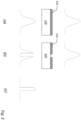
- Fig. 2 The inventive idea is schematically shown in Fig. 2 .
- a portion of the target where the target layer 210 is uniform and thus covers the target substrate 220 and at (b) there is shown a portion of the target where the target layer 210 exhibits a hole, i.e. a region in which target material is absent.
- the hole may be empty, such that the underlying substrate 220 is exposed, or it may be filled with a suitable low-Z material.
- the intensity of the incident electron beam is indicated in the top portion of Fig. 2
- the intensity of the X-ray spot is indicated at the bottom portion of Fig. 2 .
- the X-ray spot will have a smooth, gaussian-like energy distribution.
- the energy distribution in the X-ray spot will have a corresponding dent or dip.
- the electron beam may have the same size and intensity profile, as well as nominal power, both when incident upon the uniform portion of the target, as shown at (a), and when incident upon the target portion exhibiting a hole, as shown at (b).
- the electron beam may, however, in some implementations have different nominal power when directed to the first target position compared to the second target position.
- the acquired images may then be scaled, e.g. in view of dynamic range, before making the subtraction to get the difference image.
- the electron beam is blanked (to prevent X-ray generation) during the shift from the first to the second position and/or that the detector is gated in order to avoid that artifacts appear in the acquired images.
- the diameter of the hole is preferably less than 300 nm.
- a reason for making the effective X-ray spot small is to achieve high imaging resolution, i.e. to be able to resolve small details.
- the size of details that can be resolved will ultimately be limited by diffraction. Therefore, to circumvent diffraction effects, the object may be positioned close to the source.
- the distance between the source and the object is, in principle, limited by the thickness of the target (target layer and target substrate). It may thus be advantageous to reduce the target thickness and thereby the source-to-object distance.
- N F d 2 t ⁇
- d the diameter of the object (or source)
- t the source-to-object distance
- ⁇ the wavelength. Diffraction effects (Fraunhofer diffraction) will dominate when N F is below 1.
- the source-to-object distance should preferably be less than 100 ⁇ m.
- the target thickness (which typically puts a lower limit on the source-to-object distance) should preferably be less than about 100 ⁇ m.
- the controller is further configured to align (by shifting and/or rotating) the first and second images before generating the difference image.
- align can be implemented by image processing techniques which are known per se.
- the captured images may be cropped to eliminate parts of the images that are not of any interest.
- Other image processing techniques that may become useful in the acquisition of the images are noise reduction, scaling, compression, thresholding, image formatting, etc. Thresholding, for example, where relative intensity values below a threshold are set to zero or relative values above a threshold are set to one, can be useful to eliminate background artifacts outside a region of interest in the images.
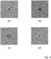
- Fig. 3 shows simulation results of X-ray images of a gold cube, having 100 nm sides, located at a distance of 100 ⁇ m from a 10 keV X-ray source.
- the simulation had an ideal detector with 100 ⁇ m pixels placed one meter from the source.
- the field of view in Fig. 3 is 2 ⁇ m by 2 ⁇ m and the images are shown in black-and-white after suitable thresholding.
- Fig. 3(a) shows a simulated image acquired using a 100 nm wide top-hat source spot distribution, and as expected the gold cube is clearly visible. Phase contrast dominates over absorption and diffraction makes the cube look circular rather than square in the image. With a 300 nm gaussian spot, the image shown in Fig.
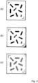
- Fig. 4 Results from an experimental test of the technology proposed herein are shown in Fig. 4 .
- the size of the electron beam spot on the target was about 12 ⁇ m (full width at half maximum).
- the field of view in Fig. 4 is about 850 ⁇ m and the images are shown in black-and-white after suitable thresholding.
- the image in Fig. 4(a) was acquired with the electron beam directed towards a normal working point on the target, i.e. a uniform target layer was used for generating the X-ray radiation.
- the image in Fig. 4(b) was acquired with the electron beam directed towards a portion of the target layer exhibiting a hole having a diameter of 3 ⁇ m.
- the image in Fig. 4(c) was obtained by subtracting the image in Fig. 4(b) from the image in Fig. 4(a) .
- the final difference image in Fig. 4(c) shows the improvement in resolution achieved using the inventive technique. From the images in Figs. 4(a) and (b) it is not evident that the eight rectangular shapes comprise five parallel bars (6 ⁇ m wide with 6 ⁇ m spacing), while this fact is clearly seen in the difference image of Fig. 4(c) .
- the sample When acquiring the X-ray images shown in Fig. 4 , the sample was not moved between the images, but the images were instead shifted a distance corresponding to the difference in electron beam positions. Thus, the artifacts appearing in the background of the difference image are likely due to secondary X-ray radiation generated upstream of the electron beam deflectors. By instead moving the sample between the two image exposures, so that the image of the sample does not move on the detector, the effect of this secondary radiation may be eliminated, or at least considerably reduced.
- the difference image in Fig. 4(c) has more background noise than the two actually acquired X-ray images. This is expected since when adding or subtracting two stochastic variables, the variance of the result will be the sum of the variances of the two variables. This means that the standard deviation of the difference image should be expected to be a factor 2 ⁇ 1.4 larger than the standard deviation of one of the images.
- the exposure time for the two acquired X-ray images may be increased. The signal-to-noise ratio is expected to increase as the square root of the number of detected X-ray photons, and thus as the square root of the integration time, i.e. to double the signal-to-noise ratio the exposure time should increase by a factor of four.
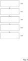
- a method for X-ray imaging according to the present invention is schematically illustrated in Fig. 5 .
- the method is performed using an X-ray source having a target arranged to produce X-ray radiation upon impact by an electron beam at an electron beam spot, wherein the target comprises a substrate and a target layer, and wherein the target layer exhibits a hole having a diameter smaller than a diameter of the electron beam spot formed on the target layer.
- the method comprises a step 510 of directing the electron beam to a first position on the target where the electron beam spot is formed at a uniform portion of the target layer away from the hole.
- a first X-ray image is acquired using a detector while the electron beam is directed to the first position.
- the electron beam is directed to a second position on the target where the electron beam spot is formed at a portion of the target exhibiting the hole, and at step 516 a second X-ray image is acquired using the detector while the electron beam is directed to the second position. Finally, at step 518, a difference image between the first image and the second image is generated.
- the order of acquiring the first and second images can be reversed. It is of course immaterial whether one of the images is acquired before the other or vice versa.
- the steps of directing the electron beam, acquiring the images, and generating the difference image are typically performed under the control of one or more processors in the X-ray system.
- the present invention can thus also be implemented as computer software comprising instructions, e.g. stored on a non-transitory computer-readable medium, which when executed cause one or more processors in the X-ray system to perform steps 510-518 discussed above.
Landscapes
- General Health & Medical Sciences (AREA)
- Health & Medical Sciences (AREA)
- Chemical & Material Sciences (AREA)
- Physics & Mathematics (AREA)
- Analytical Chemistry (AREA)
- Biochemistry (AREA)
- Life Sciences & Earth Sciences (AREA)
- General Physics & Mathematics (AREA)
- Immunology (AREA)
- Pathology (AREA)
- Toxicology (AREA)
- Analysing Materials By The Use Of Radiation (AREA)
- X-Ray Techniques (AREA)
Priority Applications (7)
| Application Number | Priority Date | Filing Date | Title |
|---|---|---|---|
| EP22195135.3A EP4336540A1 (de) | 2022-09-12 | 2022-09-12 | Röntgensystem mit kleinem target |
| JP2025514867A JP2025534863A (ja) | 2022-09-12 | 2023-09-07 | 小型ターゲットx線システム |
| EP23764337.4A EP4588088A1 (de) | 2022-09-12 | 2023-09-07 | Röntgensystem mit kleinem ziel |
| CN202380065058.1A CN119866532A (zh) | 2022-09-12 | 2023-09-07 | 小靶x射线系统 |
| PCT/EP2023/074628 WO2024056523A1 (en) | 2022-09-12 | 2023-09-07 | Small-target x-ray system |
| KR1020257011986A KR20250069616A (ko) | 2022-09-12 | 2023-09-07 | 소타겟 x-선 시스템 |
| TW112134593A TW202431306A (zh) | 2022-09-12 | 2023-09-12 | 小目標x射線系統 |
Applications Claiming Priority (1)
| Application Number | Priority Date | Filing Date | Title |
|---|---|---|---|
| EP22195135.3A EP4336540A1 (de) | 2022-09-12 | 2022-09-12 | Röntgensystem mit kleinem target |
Publications (1)
| Publication Number | Publication Date |
|---|---|
| EP4336540A1 true EP4336540A1 (de) | 2024-03-13 |
Family
ID=83283469
Family Applications (2)
| Application Number | Title | Priority Date | Filing Date |
|---|---|---|---|
| EP22195135.3A Withdrawn EP4336540A1 (de) | 2022-09-12 | 2022-09-12 | Röntgensystem mit kleinem target |
| EP23764337.4A Pending EP4588088A1 (de) | 2022-09-12 | 2023-09-07 | Röntgensystem mit kleinem ziel |
Family Applications After (1)
| Application Number | Title | Priority Date | Filing Date |
|---|---|---|---|
| EP23764337.4A Pending EP4588088A1 (de) | 2022-09-12 | 2023-09-07 | Röntgensystem mit kleinem ziel |
Country Status (6)
| Country | Link |
|---|---|
| EP (2) | EP4336540A1 (de) |
| JP (1) | JP2025534863A (de) |
| KR (1) | KR20250069616A (de) |
| CN (1) | CN119866532A (de) |
| TW (1) | TW202431306A (de) |
| WO (1) | WO2024056523A1 (de) |
Citations (2)
| Publication number | Priority date | Publication date | Assignee | Title |
|---|---|---|---|---|
| JP2002195961A (ja) * | 2000-12-25 | 2002-07-10 | Shimadzu Corp | X線撮像装置 |
| US20210233734A1 (en) * | 2018-10-22 | 2021-07-29 | Canon Anelva Corporation | X-ray generation device and x-ray image capture system |
-
2022
- 2022-09-12 EP EP22195135.3A patent/EP4336540A1/de not_active Withdrawn
-
2023
- 2023-09-07 WO PCT/EP2023/074628 patent/WO2024056523A1/en not_active Ceased
- 2023-09-07 EP EP23764337.4A patent/EP4588088A1/de active Pending
- 2023-09-07 KR KR1020257011986A patent/KR20250069616A/ko active Pending
- 2023-09-07 JP JP2025514867A patent/JP2025534863A/ja active Pending
- 2023-09-07 CN CN202380065058.1A patent/CN119866532A/zh active Pending
- 2023-09-12 TW TW112134593A patent/TW202431306A/zh unknown
Patent Citations (2)
| Publication number | Priority date | Publication date | Assignee | Title |
|---|---|---|---|---|
| JP2002195961A (ja) * | 2000-12-25 | 2002-07-10 | Shimadzu Corp | X線撮像装置 |
| US20210233734A1 (en) * | 2018-10-22 | 2021-07-29 | Canon Anelva Corporation | X-ray generation device and x-ray image capture system |
Also Published As
| Publication number | Publication date |
|---|---|
| KR20250069616A (ko) | 2025-05-19 |
| WO2024056523A1 (en) | 2024-03-21 |
| EP4588088A1 (de) | 2025-07-23 |
| CN119866532A (zh) | 2025-04-22 |
| TW202431306A (zh) | 2024-08-01 |
| JP2025534863A (ja) | 2025-10-20 |
Similar Documents
| Publication | Publication Date | Title |
|---|---|---|
| US7164126B2 (en) | Method of forming a sample image and charged particle beam apparatus | |
| US6265719B1 (en) | Inspection method and apparatus using electron beam | |
| US8592762B2 (en) | Method of using a direct electron detector for a TEM | |
| US20240272099A1 (en) | High resolution, low energy electron microscope for providing topography information and method of mask inspection | |
| JP2023110072A (ja) | 走査型電子顕微鏡および走査型電子顕微鏡の2次電子検出方法 | |
| US8644637B2 (en) | Image processing method | |
| JP3600253B2 (ja) | 電子ビーム中の空間的なエネルギー拡散を減少させる方法及び電子ビーム装置 | |
| Sukhikh et al. | Backward transition radiation in the extreme ultraviolet region as a tool for the transverse beam profile diagnostic | |
| TWI818407B (zh) | 多射束圖像取得裝置及多射束圖像取得方法 | |
| EP3594988B1 (de) | Hochleistungsfähige rasterelektronenmikroskopvorrichtung für inspektion und verfahren zum betrieb davon | |
| JP2007110087A (ja) | 電子線装置及び電子線照射パターン生成方法 | |
| EP4336540A1 (de) | Röntgensystem mit kleinem target | |
| US20080149830A1 (en) | Ameliorating charge trap in inspecting samples using scanning electron microscope | |
| JP2661908B2 (ja) | エネルギー選択可視化装置 | |
| CN110208302B (zh) | 一种粒子激发x射线荧光分析深度分辨的装置及方法 | |
| EP4266031A1 (de) | Sekundäremissionskompensation in röntgenquellen | |
| EP0555911B1 (de) | Verfahren zur Verringerung einer räumlichen energiedispersiven Streuung eines Elektronenstrahlenbündels und eine für den Einsatz eines solchen Verfahrens geeignete Elektronenstrahlvorrichtung | |
| Tkach et al. | Multi-mode lens for momentum microscopy and XPEEM: Theory | |
| JP2019169362A (ja) | 電子ビーム装置 | |
| JP2730229B2 (ja) | 荷電粒子ビーム照射型分析装置 | |
| JP6876519B2 (ja) | 荷電粒子線装置 | |
| 姜少熙 | A study on the focused ion beam sputtering for the development of 3D shave-off SIMS | |
| JP4675853B2 (ja) | 基板検査装置および基板検査方法 | |
| EP2182543B1 (de) | Verfahren und Vorrichtung für die verbesserte Ausrichtung einer Ladungsträgerteilchenkanone hoher Brillianz | |
| Kipp | Femtosecond x-ray streak cameras |
Legal Events
| Date | Code | Title | Description |
|---|---|---|---|
| PUAI | Public reference made under article 153(3) epc to a published international application that has entered the european phase |
Free format text: ORIGINAL CODE: 0009012 |
|
| STAA | Information on the status of an ep patent application or granted ep patent |
Free format text: STATUS: THE APPLICATION HAS BEEN PUBLISHED |
|
| AK | Designated contracting states |
Kind code of ref document: A1 Designated state(s): AL AT BE BG CH CY CZ DE DK EE ES FI FR GB GR HR HU IE IS IT LI LT LU LV MC MK MT NL NO PL PT RO RS SE SI SK SM TR |
|
| STAA | Information on the status of an ep patent application or granted ep patent |
Free format text: STATUS: THE APPLICATION IS DEEMED TO BE WITHDRAWN |
|
| 18D | Application deemed to be withdrawn |
Effective date: 20240914 |