EP4335834A1 - Verfahren zur herstellung eines siliciumnitridsubstrats und dadurch hergestelltes siliciumnitridsubstrat - Google Patents
Verfahren zur herstellung eines siliciumnitridsubstrats und dadurch hergestelltes siliciumnitridsubstrat Download PDFInfo
- Publication number
- EP4335834A1 EP4335834A1 EP22799110.6A EP22799110A EP4335834A1 EP 4335834 A1 EP4335834 A1 EP 4335834A1 EP 22799110 A EP22799110 A EP 22799110A EP 4335834 A1 EP4335834 A1 EP 4335834A1
- Authority
- EP
- European Patent Office
- Prior art keywords
- temperature
- section
- heat treatment
- silicon nitride
- nitrogen gas
- Prior art date
- Legal status (The legal status is an assumption and is not a legal conclusion. Google has not performed a legal analysis and makes no representation as to the accuracy of the status listed.)
- Pending
Links
- 239000000758 substrate Substances 0.000 title claims abstract description 82
- 238000000034 method Methods 0.000 title claims abstract description 71
- 229910052581 Si3N4 Inorganic materials 0.000 title claims abstract description 66
- HQVNEWCFYHHQES-UHFFFAOYSA-N silicon nitride Chemical compound N12[Si]34N5[Si]62N3[Si]51N64 HQVNEWCFYHHQES-UHFFFAOYSA-N 0.000 title claims abstract description 66
- 238000004519 manufacturing process Methods 0.000 title claims abstract description 48
- 238000005245 sintering Methods 0.000 claims abstract description 59
- 238000010438 heat treatment Methods 0.000 claims abstract description 52
- IJGRMHOSHXDMSA-UHFFFAOYSA-N Atomic nitrogen Chemical compound N#N IJGRMHOSHXDMSA-UHFFFAOYSA-N 0.000 claims abstract description 47
- XUIMIQQOPSSXEZ-UHFFFAOYSA-N Silicon Chemical compound [Si] XUIMIQQOPSSXEZ-UHFFFAOYSA-N 0.000 claims abstract description 47
- 229910001873 dinitrogen Inorganic materials 0.000 claims abstract description 47
- 239000000843 powder Substances 0.000 claims abstract description 38
- 239000000919 ceramic Substances 0.000 claims abstract description 31
- 239000000203 mixture Substances 0.000 claims abstract description 29
- 150000001875 compounds Chemical class 0.000 claims abstract description 27
- 229910052751 metal Inorganic materials 0.000 claims abstract description 26
- 239000002184 metal Substances 0.000 claims abstract description 26
- 239000011863 silicon-based powder Substances 0.000 claims abstract description 24
- 229910052710 silicon Inorganic materials 0.000 claims abstract description 23
- 239000010703 silicon Substances 0.000 claims abstract description 23
- 239000011230 binding agent Substances 0.000 claims abstract description 17
- FYYHWMGAXLPEAU-UHFFFAOYSA-N Magnesium Chemical compound [Mg] FYYHWMGAXLPEAU-UHFFFAOYSA-N 0.000 claims abstract description 14
- 229910052749 magnesium Inorganic materials 0.000 claims abstract description 14
- 239000011777 magnesium Substances 0.000 claims abstract description 14
- 229910052761 rare earth metal Inorganic materials 0.000 claims abstract description 14
- 239000002002 slurry Substances 0.000 claims abstract description 14
- 239000002904 solvent Substances 0.000 claims abstract description 12
- 238000002156 mixing Methods 0.000 claims abstract description 9
- CPLXHLVBOLITMK-UHFFFAOYSA-N magnesium oxide Inorganic materials [Mg]=O CPLXHLVBOLITMK-UHFFFAOYSA-N 0.000 claims description 20
- 239000000395 magnesium oxide Substances 0.000 claims description 20
- AXZKOIWUVFPNLO-UHFFFAOYSA-N magnesium;oxygen(2-) Chemical compound [O-2].[Mg+2] AXZKOIWUVFPNLO-UHFFFAOYSA-N 0.000 claims description 20
- SIWVEOZUMHYXCS-UHFFFAOYSA-N oxo(oxoyttriooxy)yttrium Chemical compound O=[Y]O[Y]=O SIWVEOZUMHYXCS-UHFFFAOYSA-N 0.000 claims description 20
- 239000002245 particle Substances 0.000 claims description 15
- 230000008602 contraction Effects 0.000 claims description 10
- 238000013001 point bending Methods 0.000 claims description 9
- 229910021421 monocrystalline silicon Inorganic materials 0.000 claims description 6
- 239000013078 crystal Substances 0.000 claims description 5
- 238000000227 grinding Methods 0.000 claims description 5
- 239000012535 impurity Substances 0.000 claims description 4
- 238000011109 contamination Methods 0.000 claims description 2
- 230000007704 transition Effects 0.000 abstract description 5
- 230000001133 acceleration Effects 0.000 abstract description 2
- 238000010828 elution Methods 0.000 abstract description 2
- 238000002844 melting Methods 0.000 abstract description 2
- 230000008018 melting Effects 0.000 abstract description 2
- 230000008569 process Effects 0.000 description 29
- UQSXHKLRYXJYBZ-UHFFFAOYSA-N Iron oxide Chemical compound [Fe]=O UQSXHKLRYXJYBZ-UHFFFAOYSA-N 0.000 description 14
- 238000005238 degreasing Methods 0.000 description 11
- 230000000704 physical effect Effects 0.000 description 10
- 230000000052 comparative effect Effects 0.000 description 9
- 238000001816 cooling Methods 0.000 description 8
- GWEVSGVZZGPLCZ-UHFFFAOYSA-N Titan oxide Chemical compound O=[Ti]=O GWEVSGVZZGPLCZ-UHFFFAOYSA-N 0.000 description 7
- 239000012298 atmosphere Substances 0.000 description 7
- 230000007423 decrease Effects 0.000 description 6
- UODXCYZDMHPIJE-UHFFFAOYSA-N menthanol Chemical compound CC1CCC(C(C)(C)O)CC1 UODXCYZDMHPIJE-UHFFFAOYSA-N 0.000 description 6
- OGIDPMRJRNCKJF-UHFFFAOYSA-N titanium oxide Inorganic materials [Ti]=O OGIDPMRJRNCKJF-UHFFFAOYSA-N 0.000 description 6
- 238000005452 bending Methods 0.000 description 5
- 230000001546 nitrifying effect Effects 0.000 description 5
- 239000002994 raw material Substances 0.000 description 5
- 239000000356 contaminant Substances 0.000 description 4
- ZWEHNKRNPOVVGH-UHFFFAOYSA-N 2-Butanone Chemical compound CCC(C)=O ZWEHNKRNPOVVGH-UHFFFAOYSA-N 0.000 description 3
- LYCAIKOWRPUZTN-UHFFFAOYSA-N Ethylene glycol Chemical compound OCCO LYCAIKOWRPUZTN-UHFFFAOYSA-N 0.000 description 3
- YXFVVABEGXRONW-UHFFFAOYSA-N Toluene Chemical compound CC1=CC=CC=C1 YXFVVABEGXRONW-UHFFFAOYSA-N 0.000 description 3
- QVGXLLKOCUKJST-UHFFFAOYSA-N atomic oxygen Chemical compound [O] QVGXLLKOCUKJST-UHFFFAOYSA-N 0.000 description 3
- 230000008901 benefit Effects 0.000 description 3
- 239000006227 byproduct Substances 0.000 description 3
- 238000009792 diffusion process Methods 0.000 description 3
- 238000009837 dry grinding Methods 0.000 description 3
- 239000000463 material Substances 0.000 description 3
- 238000005259 measurement Methods 0.000 description 3
- 239000001301 oxygen Substances 0.000 description 3
- 229910052760 oxygen Inorganic materials 0.000 description 3
- 229920002037 poly(vinyl butyral) polymer Polymers 0.000 description 3
- 239000004065 semiconductor Substances 0.000 description 3
- 238000010345 tape casting Methods 0.000 description 3
- DAFHKNAQFPVRKR-UHFFFAOYSA-N (3-hydroxy-2,2,4-trimethylpentyl) 2-methylpropanoate Chemical compound CC(C)C(O)C(C)(C)COC(=O)C(C)C DAFHKNAQFPVRKR-UHFFFAOYSA-N 0.000 description 2
- VXQBJTKSVGFQOL-UHFFFAOYSA-N 2-(2-butoxyethoxy)ethyl acetate Chemical compound CCCCOCCOCCOC(C)=O VXQBJTKSVGFQOL-UHFFFAOYSA-N 0.000 description 2
- HBNHCGDYYBMKJN-UHFFFAOYSA-N 2-(4-methylcyclohexyl)propan-2-yl acetate Chemical compound CC1CCC(C(C)(C)OC(C)=O)CC1 HBNHCGDYYBMKJN-UHFFFAOYSA-N 0.000 description 2
- IAZDPXIOMUYVGZ-UHFFFAOYSA-N Dimethylsulphoxide Chemical compound CS(C)=O IAZDPXIOMUYVGZ-UHFFFAOYSA-N 0.000 description 2
- LFQSCWFLJHTTHZ-UHFFFAOYSA-N Ethanol Chemical compound CCO LFQSCWFLJHTTHZ-UHFFFAOYSA-N 0.000 description 2
- YNQLUTRBYVCPMQ-UHFFFAOYSA-N Ethylbenzene Chemical compound CCC1=CC=CC=C1 YNQLUTRBYVCPMQ-UHFFFAOYSA-N 0.000 description 2
- 229910052799 carbon Inorganic materials 0.000 description 2
- RWGFKTVRMDUZSP-UHFFFAOYSA-N cumene Chemical compound CC(C)C1=CC=CC=C1 RWGFKTVRMDUZSP-UHFFFAOYSA-N 0.000 description 2
- JHIVVAPYMSGYDF-UHFFFAOYSA-N cyclohexanone Chemical compound O=C1CCCCC1 JHIVVAPYMSGYDF-UHFFFAOYSA-N 0.000 description 2
- BGTOWKSIORTVQH-UHFFFAOYSA-N cyclopentanone Chemical compound O=C1CCCC1 BGTOWKSIORTVQH-UHFFFAOYSA-N 0.000 description 2
- 238000000280 densification Methods 0.000 description 2
- FLKPEMZONWLCSK-UHFFFAOYSA-N diethyl phthalate Chemical compound CCOC(=O)C1=CC=CC=C1C(=O)OCC FLKPEMZONWLCSK-UHFFFAOYSA-N 0.000 description 2
- 229910003440 dysprosium oxide Inorganic materials 0.000 description 2
- NLQFUUYNQFMIJW-UHFFFAOYSA-N dysprosium(iii) oxide Chemical compound O=[Dy]O[Dy]=O NLQFUUYNQFMIJW-UHFFFAOYSA-N 0.000 description 2
- 230000000694 effects Effects 0.000 description 2
- 238000011156 evaluation Methods 0.000 description 2
- 229910001938 gadolinium oxide Inorganic materials 0.000 description 2
- CMIHHWBVHJVIGI-UHFFFAOYSA-N gadolinium(iii) oxide Chemical compound [O-2].[O-2].[O-2].[Gd+3].[Gd+3] CMIHHWBVHJVIGI-UHFFFAOYSA-N 0.000 description 2
- ZXEKIIBDNHEJCQ-UHFFFAOYSA-N isobutanol Chemical compound CC(C)CO ZXEKIIBDNHEJCQ-UHFFFAOYSA-N 0.000 description 2
- 239000012299 nitrogen atmosphere Substances 0.000 description 2
- 230000035939 shock Effects 0.000 description 2
- 238000007655 standard test method Methods 0.000 description 2
- 238000005406 washing Methods 0.000 description 2
- OAYXUHPQHDHDDZ-UHFFFAOYSA-N 2-(2-butoxyethoxy)ethanol Chemical compound CCCCOCCOCCO OAYXUHPQHDHDDZ-UHFFFAOYSA-N 0.000 description 1
- OKTJSMMVPCPJKN-UHFFFAOYSA-N Carbon Chemical compound [C] OKTJSMMVPCPJKN-UHFFFAOYSA-N 0.000 description 1
- VGGSQFUCUMXWEO-UHFFFAOYSA-N Ethene Chemical compound C=C VGGSQFUCUMXWEO-UHFFFAOYSA-N 0.000 description 1
- 239000001856 Ethyl cellulose Substances 0.000 description 1
- ZZSNKZQZMQGXPY-UHFFFAOYSA-N Ethyl cellulose Chemical compound CCOCC1OC(OC)C(OCC)C(OCC)C1OC1C(O)C(O)C(OC)C(CO)O1 ZZSNKZQZMQGXPY-UHFFFAOYSA-N 0.000 description 1
- 239000005977 Ethylene Substances 0.000 description 1
- 239000000020 Nitrocellulose Substances 0.000 description 1
- 208000012868 Overgrowth Diseases 0.000 description 1
- 239000004372 Polyvinyl alcohol Substances 0.000 description 1
- 239000002253 acid Substances 0.000 description 1
- 125000005396 acrylic acid ester group Chemical group 0.000 description 1
- 229910000287 alkaline earth metal oxide Inorganic materials 0.000 description 1
- WUOACPNHFRMFPN-UHFFFAOYSA-N alpha-terpineol Chemical compound CC1=CCC(C(C)(C)O)CC1 WUOACPNHFRMFPN-UHFFFAOYSA-N 0.000 description 1
- 238000005266 casting Methods 0.000 description 1
- 239000001913 cellulose Substances 0.000 description 1
- 229920002678 cellulose Polymers 0.000 description 1
- 230000008859 change Effects 0.000 description 1
- 238000006243 chemical reaction Methods 0.000 description 1
- 239000003795 chemical substances by application Substances 0.000 description 1
- 230000007797 corrosion Effects 0.000 description 1
- 238000005260 corrosion Methods 0.000 description 1
- 238000000354 decomposition reaction Methods 0.000 description 1
- 230000007547 defect Effects 0.000 description 1
- SQIFACVGCPWBQZ-UHFFFAOYSA-N delta-terpineol Natural products CC(C)(O)C1CCC(=C)CC1 SQIFACVGCPWBQZ-UHFFFAOYSA-N 0.000 description 1
- 238000010586 diagram Methods 0.000 description 1
- 239000002270 dispersing agent Substances 0.000 description 1
- 238000004090 dissolution Methods 0.000 description 1
- ZXGIFJXRQHZCGJ-UHFFFAOYSA-N erbium(3+);oxygen(2-) Chemical compound [O-2].[O-2].[O-2].[Er+3].[Er+3] ZXGIFJXRQHZCGJ-UHFFFAOYSA-N 0.000 description 1
- 229920001249 ethyl cellulose Polymers 0.000 description 1
- 235000019325 ethyl cellulose Nutrition 0.000 description 1
- 230000001747 exhibiting effect Effects 0.000 description 1
- 229940075613 gadolinium oxide Drugs 0.000 description 1
- 239000007789 gas Substances 0.000 description 1
- 230000017525 heat dissipation Effects 0.000 description 1
- OWCYYNSBGXMRQN-UHFFFAOYSA-N holmium(3+);oxygen(2-) Chemical compound [O-2].[O-2].[O-2].[Ho+3].[Ho+3] OWCYYNSBGXMRQN-UHFFFAOYSA-N 0.000 description 1
- 230000006872 improvement Effects 0.000 description 1
- 239000011261 inert gas Substances 0.000 description 1
- 229940035429 isobutyl alcohol Drugs 0.000 description 1
- 150000002739 metals Chemical class 0.000 description 1
- 125000005397 methacrylic acid ester group Chemical group 0.000 description 1
- 229920000609 methyl cellulose Polymers 0.000 description 1
- 239000001923 methylcellulose Substances 0.000 description 1
- 235000010981 methylcellulose Nutrition 0.000 description 1
- 238000000465 moulding Methods 0.000 description 1
- 229920001220 nitrocellulos Polymers 0.000 description 1
- 150000002894 organic compounds Chemical class 0.000 description 1
- 239000004014 plasticizer Substances 0.000 description 1
- 229910021420 polycrystalline silicon Inorganic materials 0.000 description 1
- 239000002952 polymeric resin Substances 0.000 description 1
- 229920002451 polyvinyl alcohol Polymers 0.000 description 1
- 238000002360 preparation method Methods 0.000 description 1
- 238000011160 research Methods 0.000 description 1
- 238000004904 shortening Methods 0.000 description 1
- 238000009628 steelmaking Methods 0.000 description 1
- 229920003002 synthetic resin Polymers 0.000 description 1
- 229940116411 terpineol Drugs 0.000 description 1
- 238000012360 testing method Methods 0.000 description 1
- 230000008646 thermal stress Effects 0.000 description 1
- FIXNOXLJNSSSLJ-UHFFFAOYSA-N ytterbium(III) oxide Inorganic materials O=[Yb]O[Yb]=O FIXNOXLJNSSSLJ-UHFFFAOYSA-N 0.000 description 1
Images

Classifications
-
- C—CHEMISTRY; METALLURGY
- C04—CEMENTS; CONCRETE; ARTIFICIAL STONE; CERAMICS; REFRACTORIES
- C04B—LIME, MAGNESIA; SLAG; CEMENTS; COMPOSITIONS THEREOF, e.g. MORTARS, CONCRETE OR LIKE BUILDING MATERIALS; ARTIFICIAL STONE; CERAMICS; REFRACTORIES; TREATMENT OF NATURAL STONE
- C04B35/00—Shaped ceramic products characterised by their composition; Ceramics compositions; Processing powders of inorganic compounds preparatory to the manufacturing of ceramic products
- C04B35/515—Shaped ceramic products characterised by their composition; Ceramics compositions; Processing powders of inorganic compounds preparatory to the manufacturing of ceramic products based on non-oxide ceramics
- C04B35/58—Shaped ceramic products characterised by their composition; Ceramics compositions; Processing powders of inorganic compounds preparatory to the manufacturing of ceramic products based on non-oxide ceramics based on borides, nitrides, i.e. nitrides, oxynitrides, carbonitrides or oxycarbonitrides or silicides
- C04B35/584—Shaped ceramic products characterised by their composition; Ceramics compositions; Processing powders of inorganic compounds preparatory to the manufacturing of ceramic products based on non-oxide ceramics based on borides, nitrides, i.e. nitrides, oxynitrides, carbonitrides or oxycarbonitrides or silicides based on silicon nitride
- C04B35/591—Shaped ceramic products characterised by their composition; Ceramics compositions; Processing powders of inorganic compounds preparatory to the manufacturing of ceramic products based on non-oxide ceramics based on borides, nitrides, i.e. nitrides, oxynitrides, carbonitrides or oxycarbonitrides or silicides based on silicon nitride obtained by reaction sintering
-
- C—CHEMISTRY; METALLURGY
- C04—CEMENTS; CONCRETE; ARTIFICIAL STONE; CERAMICS; REFRACTORIES
- C04B—LIME, MAGNESIA; SLAG; CEMENTS; COMPOSITIONS THEREOF, e.g. MORTARS, CONCRETE OR LIKE BUILDING MATERIALS; ARTIFICIAL STONE; CERAMICS; REFRACTORIES; TREATMENT OF NATURAL STONE
- C04B35/00—Shaped ceramic products characterised by their composition; Ceramics compositions; Processing powders of inorganic compounds preparatory to the manufacturing of ceramic products
- C04B35/515—Shaped ceramic products characterised by their composition; Ceramics compositions; Processing powders of inorganic compounds preparatory to the manufacturing of ceramic products based on non-oxide ceramics
- C04B35/58—Shaped ceramic products characterised by their composition; Ceramics compositions; Processing powders of inorganic compounds preparatory to the manufacturing of ceramic products based on non-oxide ceramics based on borides, nitrides, i.e. nitrides, oxynitrides, carbonitrides or oxycarbonitrides or silicides
- C04B35/584—Shaped ceramic products characterised by their composition; Ceramics compositions; Processing powders of inorganic compounds preparatory to the manufacturing of ceramic products based on non-oxide ceramics based on borides, nitrides, i.e. nitrides, oxynitrides, carbonitrides or oxycarbonitrides or silicides based on silicon nitride
- C04B35/593—Shaped ceramic products characterised by their composition; Ceramics compositions; Processing powders of inorganic compounds preparatory to the manufacturing of ceramic products based on non-oxide ceramics based on borides, nitrides, i.e. nitrides, oxynitrides, carbonitrides or oxycarbonitrides or silicides based on silicon nitride obtained by pressure sintering
- C04B35/5935—Shaped ceramic products characterised by their composition; Ceramics compositions; Processing powders of inorganic compounds preparatory to the manufacturing of ceramic products based on non-oxide ceramics based on borides, nitrides, i.e. nitrides, oxynitrides, carbonitrides or oxycarbonitrides or silicides based on silicon nitride obtained by pressure sintering obtained by gas pressure sintering
-
- C—CHEMISTRY; METALLURGY
- C04—CEMENTS; CONCRETE; ARTIFICIAL STONE; CERAMICS; REFRACTORIES
- C04B—LIME, MAGNESIA; SLAG; CEMENTS; COMPOSITIONS THEREOF, e.g. MORTARS, CONCRETE OR LIKE BUILDING MATERIALS; ARTIFICIAL STONE; CERAMICS; REFRACTORIES; TREATMENT OF NATURAL STONE
- C04B35/00—Shaped ceramic products characterised by their composition; Ceramics compositions; Processing powders of inorganic compounds preparatory to the manufacturing of ceramic products
- C04B35/622—Forming processes; Processing powders of inorganic compounds preparatory to the manufacturing of ceramic products
- C04B35/626—Preparing or treating the powders individually or as batches ; preparing or treating macroscopic reinforcing agents for ceramic products, e.g. fibres; mechanical aspects section B
- C04B35/63—Preparing or treating the powders individually or as batches ; preparing or treating macroscopic reinforcing agents for ceramic products, e.g. fibres; mechanical aspects section B using additives specially adapted for forming the products, e.g.. binder binders
- C04B35/632—Organic additives
- C04B35/634—Polymers
- C04B35/63404—Polymers obtained by reactions only involving carbon-to-carbon unsaturated bonds
- C04B35/6342—Polyvinylacetals, e.g. polyvinylbutyral [PVB]
-
- C—CHEMISTRY; METALLURGY
- C04—CEMENTS; CONCRETE; ARTIFICIAL STONE; CERAMICS; REFRACTORIES
- C04B—LIME, MAGNESIA; SLAG; CEMENTS; COMPOSITIONS THEREOF, e.g. MORTARS, CONCRETE OR LIKE BUILDING MATERIALS; ARTIFICIAL STONE; CERAMICS; REFRACTORIES; TREATMENT OF NATURAL STONE
- C04B35/00—Shaped ceramic products characterised by their composition; Ceramics compositions; Processing powders of inorganic compounds preparatory to the manufacturing of ceramic products
- C04B35/622—Forming processes; Processing powders of inorganic compounds preparatory to the manufacturing of ceramic products
- C04B35/64—Burning or sintering processes
-
- C—CHEMISTRY; METALLURGY
- C04—CEMENTS; CONCRETE; ARTIFICIAL STONE; CERAMICS; REFRACTORIES
- C04B—LIME, MAGNESIA; SLAG; CEMENTS; COMPOSITIONS THEREOF, e.g. MORTARS, CONCRETE OR LIKE BUILDING MATERIALS; ARTIFICIAL STONE; CERAMICS; REFRACTORIES; TREATMENT OF NATURAL STONE
- C04B2235/00—Aspects relating to ceramic starting mixtures or sintered ceramic products
- C04B2235/02—Composition of constituents of the starting material or of secondary phases of the final product
- C04B2235/30—Constituents and secondary phases not being of a fibrous nature
- C04B2235/32—Metal oxides, mixed metal oxides, or oxide-forming salts thereof, e.g. carbonates, nitrates, (oxy)hydroxides, chlorides
- C04B2235/3205—Alkaline earth oxides or oxide forming salts thereof, e.g. beryllium oxide
- C04B2235/3206—Magnesium oxides or oxide-forming salts thereof
-
- C—CHEMISTRY; METALLURGY
- C04—CEMENTS; CONCRETE; ARTIFICIAL STONE; CERAMICS; REFRACTORIES
- C04B—LIME, MAGNESIA; SLAG; CEMENTS; COMPOSITIONS THEREOF, e.g. MORTARS, CONCRETE OR LIKE BUILDING MATERIALS; ARTIFICIAL STONE; CERAMICS; REFRACTORIES; TREATMENT OF NATURAL STONE
- C04B2235/00—Aspects relating to ceramic starting mixtures or sintered ceramic products
- C04B2235/02—Composition of constituents of the starting material or of secondary phases of the final product
- C04B2235/30—Constituents and secondary phases not being of a fibrous nature
- C04B2235/32—Metal oxides, mixed metal oxides, or oxide-forming salts thereof, e.g. carbonates, nitrates, (oxy)hydroxides, chlorides
- C04B2235/3224—Rare earth oxide or oxide forming salts thereof, e.g. scandium oxide
- C04B2235/3225—Yttrium oxide or oxide-forming salts thereof
-
- C—CHEMISTRY; METALLURGY
- C04—CEMENTS; CONCRETE; ARTIFICIAL STONE; CERAMICS; REFRACTORIES
- C04B—LIME, MAGNESIA; SLAG; CEMENTS; COMPOSITIONS THEREOF, e.g. MORTARS, CONCRETE OR LIKE BUILDING MATERIALS; ARTIFICIAL STONE; CERAMICS; REFRACTORIES; TREATMENT OF NATURAL STONE
- C04B2235/00—Aspects relating to ceramic starting mixtures or sintered ceramic products
- C04B2235/02—Composition of constituents of the starting material or of secondary phases of the final product
- C04B2235/30—Constituents and secondary phases not being of a fibrous nature
- C04B2235/38—Non-oxide ceramic constituents or additives
- C04B2235/3852—Nitrides, e.g. oxynitrides, carbonitrides, oxycarbonitrides, lithium nitride, magnesium nitride
- C04B2235/3873—Silicon nitrides, e.g. silicon carbonitride, silicon oxynitride
-
- C—CHEMISTRY; METALLURGY
- C04—CEMENTS; CONCRETE; ARTIFICIAL STONE; CERAMICS; REFRACTORIES
- C04B—LIME, MAGNESIA; SLAG; CEMENTS; COMPOSITIONS THEREOF, e.g. MORTARS, CONCRETE OR LIKE BUILDING MATERIALS; ARTIFICIAL STONE; CERAMICS; REFRACTORIES; TREATMENT OF NATURAL STONE
- C04B2235/00—Aspects relating to ceramic starting mixtures or sintered ceramic products
- C04B2235/02—Composition of constituents of the starting material or of secondary phases of the final product
- C04B2235/30—Constituents and secondary phases not being of a fibrous nature
- C04B2235/42—Non metallic elements added as constituents or additives, e.g. sulfur, phosphor, selenium or tellurium
- C04B2235/428—Silicon
-
- C—CHEMISTRY; METALLURGY
- C04—CEMENTS; CONCRETE; ARTIFICIAL STONE; CERAMICS; REFRACTORIES
- C04B—LIME, MAGNESIA; SLAG; CEMENTS; COMPOSITIONS THEREOF, e.g. MORTARS, CONCRETE OR LIKE BUILDING MATERIALS; ARTIFICIAL STONE; CERAMICS; REFRACTORIES; TREATMENT OF NATURAL STONE
- C04B2235/00—Aspects relating to ceramic starting mixtures or sintered ceramic products
- C04B2235/02—Composition of constituents of the starting material or of secondary phases of the final product
- C04B2235/50—Constituents or additives of the starting mixture chosen for their shape or used because of their shape or their physical appearance
- C04B2235/54—Particle size related information
- C04B2235/5418—Particle size related information expressed by the size of the particles or aggregates thereof
- C04B2235/5436—Particle size related information expressed by the size of the particles or aggregates thereof micrometer sized, i.e. from 1 to 100 micron
-
- C—CHEMISTRY; METALLURGY
- C04—CEMENTS; CONCRETE; ARTIFICIAL STONE; CERAMICS; REFRACTORIES
- C04B—LIME, MAGNESIA; SLAG; CEMENTS; COMPOSITIONS THEREOF, e.g. MORTARS, CONCRETE OR LIKE BUILDING MATERIALS; ARTIFICIAL STONE; CERAMICS; REFRACTORIES; TREATMENT OF NATURAL STONE
- C04B2235/00—Aspects relating to ceramic starting mixtures or sintered ceramic products
- C04B2235/02—Composition of constituents of the starting material or of secondary phases of the final product
- C04B2235/50—Constituents or additives of the starting mixture chosen for their shape or used because of their shape or their physical appearance
- C04B2235/54—Particle size related information
- C04B2235/5418—Particle size related information expressed by the size of the particles or aggregates thereof
- C04B2235/5445—Particle size related information expressed by the size of the particles or aggregates thereof submicron sized, i.e. from 0,1 to 1 micron
-
- C—CHEMISTRY; METALLURGY
- C04—CEMENTS; CONCRETE; ARTIFICIAL STONE; CERAMICS; REFRACTORIES
- C04B—LIME, MAGNESIA; SLAG; CEMENTS; COMPOSITIONS THEREOF, e.g. MORTARS, CONCRETE OR LIKE BUILDING MATERIALS; ARTIFICIAL STONE; CERAMICS; REFRACTORIES; TREATMENT OF NATURAL STONE
- C04B2235/00—Aspects relating to ceramic starting mixtures or sintered ceramic products
- C04B2235/60—Aspects relating to the preparation, properties or mechanical treatment of green bodies or pre-forms
- C04B2235/602—Making the green bodies or pre-forms by moulding
- C04B2235/6025—Tape casting, e.g. with a doctor blade
-
- C—CHEMISTRY; METALLURGY
- C04—CEMENTS; CONCRETE; ARTIFICIAL STONE; CERAMICS; REFRACTORIES
- C04B—LIME, MAGNESIA; SLAG; CEMENTS; COMPOSITIONS THEREOF, e.g. MORTARS, CONCRETE OR LIKE BUILDING MATERIALS; ARTIFICIAL STONE; CERAMICS; REFRACTORIES; TREATMENT OF NATURAL STONE
- C04B2235/00—Aspects relating to ceramic starting mixtures or sintered ceramic products
- C04B2235/65—Aspects relating to heat treatments of ceramic bodies such as green ceramics or pre-sintered ceramics, e.g. burning, sintering or melting processes
- C04B2235/656—Aspects relating to heat treatments of ceramic bodies such as green ceramics or pre-sintered ceramics, e.g. burning, sintering or melting processes characterised by specific heating conditions during heat treatment
- C04B2235/6562—Heating rate
-
- C—CHEMISTRY; METALLURGY
- C04—CEMENTS; CONCRETE; ARTIFICIAL STONE; CERAMICS; REFRACTORIES
- C04B—LIME, MAGNESIA; SLAG; CEMENTS; COMPOSITIONS THEREOF, e.g. MORTARS, CONCRETE OR LIKE BUILDING MATERIALS; ARTIFICIAL STONE; CERAMICS; REFRACTORIES; TREATMENT OF NATURAL STONE
- C04B2235/00—Aspects relating to ceramic starting mixtures or sintered ceramic products
- C04B2235/65—Aspects relating to heat treatments of ceramic bodies such as green ceramics or pre-sintered ceramics, e.g. burning, sintering or melting processes
- C04B2235/656—Aspects relating to heat treatments of ceramic bodies such as green ceramics or pre-sintered ceramics, e.g. burning, sintering or melting processes characterised by specific heating conditions during heat treatment
- C04B2235/6567—Treatment time
-
- C—CHEMISTRY; METALLURGY
- C04—CEMENTS; CONCRETE; ARTIFICIAL STONE; CERAMICS; REFRACTORIES
- C04B—LIME, MAGNESIA; SLAG; CEMENTS; COMPOSITIONS THEREOF, e.g. MORTARS, CONCRETE OR LIKE BUILDING MATERIALS; ARTIFICIAL STONE; CERAMICS; REFRACTORIES; TREATMENT OF NATURAL STONE
- C04B2235/00—Aspects relating to ceramic starting mixtures or sintered ceramic products
- C04B2235/65—Aspects relating to heat treatments of ceramic bodies such as green ceramics or pre-sintered ceramics, e.g. burning, sintering or melting processes
- C04B2235/658—Atmosphere during thermal treatment
- C04B2235/6586—Processes characterised by the flow of gas
-
- C—CHEMISTRY; METALLURGY
- C04—CEMENTS; CONCRETE; ARTIFICIAL STONE; CERAMICS; REFRACTORIES
- C04B—LIME, MAGNESIA; SLAG; CEMENTS; COMPOSITIONS THEREOF, e.g. MORTARS, CONCRETE OR LIKE BUILDING MATERIALS; ARTIFICIAL STONE; CERAMICS; REFRACTORIES; TREATMENT OF NATURAL STONE
- C04B2235/00—Aspects relating to ceramic starting mixtures or sintered ceramic products
- C04B2235/70—Aspects relating to sintered or melt-casted ceramic products
- C04B2235/96—Properties of ceramic products, e.g. mechanical properties such as strength, toughness, wear resistance
- C04B2235/9607—Thermal properties, e.g. thermal expansion coefficient
-
- C—CHEMISTRY; METALLURGY
- C04—CEMENTS; CONCRETE; ARTIFICIAL STONE; CERAMICS; REFRACTORIES
- C04B—LIME, MAGNESIA; SLAG; CEMENTS; COMPOSITIONS THEREOF, e.g. MORTARS, CONCRETE OR LIKE BUILDING MATERIALS; ARTIFICIAL STONE; CERAMICS; REFRACTORIES; TREATMENT OF NATURAL STONE
- C04B35/00—Shaped ceramic products characterised by their composition; Ceramics compositions; Processing powders of inorganic compounds preparatory to the manufacturing of ceramic products
- C04B35/622—Forming processes; Processing powders of inorganic compounds preparatory to the manufacturing of ceramic products
- C04B35/62204—Forming processes; Processing powders of inorganic compounds preparatory to the manufacturing of ceramic products using waste materials or refuse
Definitions
- the present invention relates to a method for manufacturing a silicon nitride substrate and a silicon nitride substrate manufactured therefrom.
- the silicon nitride sintered body is excellent in wear resistance, heat resistance, low thermal expansion resistance, thermal shock resistance and corrosion resistance to metals, and it has been conventionally used for various structural members such as gas turbine members, engine members, steelmaking machine members and the like. In addition, due to its high insulating properties and excellent heat dissipation properties, it is used as a material for electrical components such as ceramic substrates and the like.
- the silicon nitride substrate has been conventionally manufactured by a two-step method of manufacturing silicon nitride powder and then sintering the manufactured silicon nitride powder.
- the reason why such a method is adopted is that it is difficult to implement a substrate that expresses uniform physical properties, regardless of the position during nitrification and sintering in the form of a substrate, and in order to solve this problem, the method of first manufacturing silicon nitride powder to have uniform physical properties in powder form and then using the same to manufacture a substrate has been widely used.
- the nitrified body after nitrification, the nitrified body must be cooled/pulverized, molded again to have a predetermined shape and then sintered, and therefore, the manufacturing time takes more than 50 hours, and there is a concern that man-hours will increase.
- the situation is that research on a method for manufacturing a silicon nitride substrate that can dramatically reduce the manufacturing time while also reducing man-hours, and that the implemented silicon nitride substrate has excellent thermal conductivity and mechanical strength while exhibiting these physical properties uniformly at each location of the substrate is urgently needed.
- Patent Document 1 Korean Patent Application Laid-Open No. 10-1997-7000234
- the present invention has been devised in view of the above points, and it is possible to manufacture a silicon nitride substrate by reducing the manufacturing time and man-hours compared to the conventional silicon nitride substrate manufacturing method, and the present invention is directed to providing a method for manufacturing a silicon nitride substrate in which the implemented silicon nitride substrate has excellent flatness, thermal conductivity and mechanical strength, and at the same time, these physical properties are uniformly expressed at each position of the substrate, and a silicon nitride substrate manufactured therefrom.
- the present invention has been devised in view of the above points, and provides a method for manufacturing a silicon nitride (Si 3 N 4 ) substrate, including the steps of preparing a ceramic composition including a metal silicon powder and a crystalline phase control powder including a rare earth element-containing compound and a magnesium-containing compound; manufacturing a sheet-shaped molded body of a slurry prepared by mixing a solvent and an organic binder with the ceramic composition; and performing heat treatment including a nitrification section where heat treatment is performed at a first temperature in the range of 1,300 to 1,500°C together with the application of nitrogen gas to the molded body at a predetermined pressure and a sintering section where heat treatment is performed at a second temperature in the range of 1,700 to 1,900°C.
- the metal silicon powder may be a dry-ground polycrystalline metal silicon scrap or single-crystal silicon wafer scrap in order to minimize contamination with metal impurities during grinding.
- the metal silicon powder may have a resistivity of 1 to 100 ⁇ cm.
- polycrystalline metal silicon scrap or single-crystal metal silicon wafer scrap may have a purity of 99% or more.
- the rare earth element-containing compound may be yttrium oxide
- the magnesium-containing compound may be magnesium oxide
- the ceramic composition may include 2 to 5 mol% of yttrium oxide and 2 to 10 mol% of magnesium oxide.
- the metallic silicon powder may have an average particle diameter of 0.5 to 4 ⁇ m
- the rare earth element-containing compound powder may have an average particle diameter of 0.1 to 1 ⁇ m
- the magnesium-containing compound powder may have an average particle diameter of 0.1 to 1 ⁇ m.
- the heat treatment step may be performed continuously from the nitrification section to the sintering section.
- a section in which heat treatment is performed to a temperature lower than the first temperature or cooling is performed to a temperature lower than the first temperature may not be included between the nitrification section and the sintering section.
- the heat treatment step may be performed at a temperature increase rate of 0.1 to 2°C/min while applying nitrogen gas at a pressure of 0.1 to 0.2 MPa from 1,000 ⁇ 20°C to the first temperature.
- nitrogen gas may be applied at a pressure of 0.1 to 0.2 MPa, and the nitrification section may be performed for 2 to 10 hours.
- the pressure of nitrogen gas applied from 1,000 ⁇ 20°C to the first temperature may be lower than the pressure of nitrogen gas applied in the nitrification section.
- the method may further include a first contraction section which is heated at a rate of 0.1 to 10.0°C/min under a nitrogen gas pressure of 0.15 to 0.30 MPa from the first temperature to 1,700 ⁇ 20°C, and a second contraction section which is heated from 1,700 ⁇ 20°C to the second temperature at a rate of 1 to 10°C/min under a nitrogen gas pressure of 0.80 to 0.98 MPa between the nitrification section and the sintering section.
- a first contraction section which is heated at a rate of 0.1 to 10.0°C/min under a nitrogen gas pressure of 0.15 to 0.30 MPa from the first temperature to 1,700 ⁇ 20°C
- a second contraction section which is heated from 1,700 ⁇ 20°C to the second temperature at a rate of 1 to 10°C/min under a nitrogen gas pressure of 0.80 to 0.98 MPa between the nitrification section and the sintering section.
- the present invention provides a silicon nitride substrate, which is manufactured through the method according to the present invention, wherein the thermal conductivity is 75W/mK or more, and the 3-point bending strength is 700 MPa or more.
- the method for manufacturing a silicon nitride substrate according to the present invention can reduce the manufacturing time and manpower and thus is suitable for mass production. Additionally, the implemented silicon nitride substrate has excellent mechanical strength since the melting and elution of silicon can be minimized or prevented during nitrification. Furthermore, sintering is completed after entering the sintering section while the rapid transition to a beta phase is suppressed, and thus the transition to the beta phase, the acceleration of beta phase growth, and uniform growth can be attained, leading to more improved thermal conductivity. Moreover, thermal conductivity and mechanical strength are uniform regardless of the site on the substrate, so that a higher-quality substrate can be attained.
- the silicon nitride substrate according to an exemplary embodiment of the present invention may be manufactured by including the steps of preparing a ceramic composition including a metal silicon powder and a crystalline phase control powder including a rare earth element-containing compound and a magnesium-containing compound; manufacturing a sheet-shaped molded body of a slurry prepared by mixing a solvent and an organic binder with the ceramic composition; and performing heat treatment including a nitrification section where heat treatment is performed at a first temperature in the range of 1,300 to 1,500°C together with the application of nitrogen gas to the molded body at a predetermined pressure and a sintering section where heat treatment is performed at a second temperature in the range of 1,700 to 1,900°C.
- the ceramic composition may be prepared by mixing a ceramic composition including a metal silicon powder and a crystalline phase control powder including a rare earth element-containing compound and a magnesium-containing compound.
- the metallic silicon powder which is the main subject as the raw material powder, may be used without limitation in the case of silicon nitride powder or metallic silicon powder used for manufacturing a silicon nitride compact through direct nitrification.
- the metal silicon powder may be a polycrystalline metal silicon scrap or single-crystal silicon wafer scrap.
- the polycrystalline metallic silicon scrap may be a by-product of polycrystalline metallic silicon used for manufacturing jigs for semiconductor processes or solar panels, and the single-crystal silicon wafer scrap may also be a by-product during silicon wafer manufacturing, and thus, these scraps, which are byproducts, may be used as raw material powder and through this, it is possible to lower the manufacturing cost.
- the polycrystalline metal silicon scrap or single-crystal silicon wafer scrap may have a purity of 99% or more, and through this, it may be more advantageous in ensuring thermal conductivity and mechanical strength of the implemented silicon nitride substrate.
- the metal silicon powder may have a resistivity of 1 to 100 Q cm, which may be more advantageous in terms of manufacturing a silicon nitride substrate having physical properties desired by the present invention.
- the metal silicon powder used as the raw material powder may be preferably a polycrystalline metal silicon scrap or single-crystal silicon wafer scrap that is ground to a predetermined size.
- the grinding may be performed by using a dry grinding method, and specifically, it may be powdered by using dry grinding methods such as disk mill, pin mill, jet mill and the like. If the contaminants are contained in the metallic silicon powder, there is a risk of increasing the manufacturing time and cost, which requires further washing processes such as acid washing in order to remove the contaminants.
- the average particle diameter of the ground metal silicon powder may be 0.5 to 4 ⁇ m, and more preferably, 2 to 4 ⁇ m, and if the average particle diameter is less than 0.5 ⁇ m, it may be difficult to implement through the dry grinding method, and there is a concern that the possibility of contaminants mixing therein due to fine powder, and densification may be difficult during sheet casting.
- the average particle diameter of the metallic silicon powder is more than 4 ⁇ m, nitrification is not easy, and thus, there is a concern that a non-nitrified portion may exist, and densification of the finally implemented substrate may be difficult.
- silicon nitride which is the material of the substrate to be implemented, is difficult for self-diffusion and may be thermally decomposed at high temperature, and thus, it is not easy to sinter as a substrate for reasons such as limited sintering temperature, and it may be difficult to implement a dense and uniformly nitrified substrate. Therefore, in order to solve these difficulties and improve the physical properties of a silicon nitride substrate by removing impurities such as oxygen and the like, a ceramic composition obtained by mixing a metallic silicon powder with a crystalline phase control powder is used as the raw material powder.
- a rare earth element-containing compound containing, an alkaline earth metal oxide or a combination thereof may be used, and specifically, at least one selected from the group consisting of magnesium oxide (MgO), yttrium oxide (Y 2 O 3 ), gadolinium oxide (Gd 2 O), holmium oxide (Ho 2 O 3 ), erbium oxide (Er 2 O 3 ), irtebium oxide (Yb 2 O 3 ) and dysprosium oxide (Dy 2 O 3 ) may be used.
- the present invention essentially contains magnesium oxide and yttrium oxide in the crystalline phase control powder in order to make it easier to sinter and control the crystalline phase of the silicon nitride substrate, and the magnesium oxide and yttrium oxide have the advantages of making the manufactured silicon nitride substrate more dense and having a higher density, and further improving the thermal conductivity of a substrate by reducing the amount of residual grain boundary phases during sintering.
- the ceramic composition containing silicon may further contain a strength-enhancing powder including at least any eon of iron oxide (Fe 2 O 3 ) and titanium oxide (TiO 2 ) in order to improve mechanical strength due to thermal stress or thermal shock according to the severe semiconductor manufacturing process, and preferably, the strength-enhancing powder may contain both of iron oxide and titanium oxide.
- a strength-enhancing powder including at least any eon of iron oxide (Fe 2 O 3 ) and titanium oxide (TiO 2 ) in order to improve mechanical strength due to thermal stress or thermal shock according to the severe semiconductor manufacturing process, and preferably, the strength-enhancing powder may contain both of iron oxide and titanium oxide.
- the heat treatment step to be described below proceeds in one step through continuous heat treatment in one sintering furnace without nitrification and sintering in a separate furnace, and the combination of magnesium oxide and yttrium oxide, or the combination of magnesium oxide, yttrium oxide, iron oxide and titanium oxide may be useful for nitrifying and sintering metallic silicon powder to silicon nitride.
- nitrification and sintering are carried out in a separate furnace or nitrification is performed followed by cooling and sintering is performed, but in a one-step process that proceeds from nitrification to sintering in one step after charging the silicon-containing ceramic composition into the furnace, it may not be easy to implement a densified sintered body that is uniformly nitrified to the inside of the molded body without silicon eluting, and the above-described crystalline control powder contained in the ceramic composition or the strength-improving powder included together with the crystalline control powder may be useful in implementing a uniformly nitrified and densified sintered body.
- the ceramic composition may include 2 to 5 mol% of yttrium oxide and 2 to 10 mol% of magnesium oxide (preferably, 4 to 8 mol%).
- 0.1 to 3 mol% of iron oxide and 1 to 5 mol% of titanium oxide may be further included based on the total number of moles of the ceramic composition, and through this, even by performing a one-step nitrification-sintering process, it is possible to have further improved mechanical strength.
- yttrium oxide is less than 2 mol%, when sintering a substrate, it may be difficult to implement a densified substrate, and it may be difficult to capture oxygen on grain boundaries, which may result in an increased amount of dissolved oxygen, and it may lower the thermal conductivity of the sintered substrate and lower the mechanical strength thereof.
- yttrium oxide is more than 5 mol%, there is a concern that the thermal conductivity of the silicon nitride substrate implemented as the grain boundary phase increases, and the fracture toughness decreases.
- magnesium oxide is less than 2 mol%, both of the thermal conductivity and mechanical strength of the implemented silicon nitride substrate may be low, there is a risk of silicon being eluted during nitrification, and it may be difficult to manufacture a densified substrate.
- magnesium oxide is more than 10 mol%, during sintering, the amount of magnesium remaining at the grain boundaries increases, and as a result, it may lower the thermal conductivity of the implemented substrate, make sintering difficult, and fracture toughness may decrease.
- iron oxide is less than 0.1 mol% and/or titanium oxide is less than 1 mol%, the improvement of mechanical strength may be minimal.
- iron oxide is more than 3 mol% and/or titanium oxide is more than 5 mol%, there is a concern that the mechanical strength of the sintered body may decrease.
- the yttrium oxide and magnesium oxide may be included in the composition at a molar ratio of 1: 1.5 to 2.0, which may be more advantageous in achieving the objects of the present invention.
- the rare earth element-containing compound powder may have an average particle diameter of 0.1 to 1 ⁇ m
- the magnesium-containing compound powder may have an average particle diameter of 0.1 to 1 ⁇ m, which may be more advantageous to achieve the objects of the present invention.
- the step of mixing the prepared ceramic composition with a solvent and an organic binder to form a slurry, and then preparing a sheet-shaped molded body is performed.
- the solvent and organic binder may be used without limitation in the case of known solvents and organic binders that are used in manufacturing a ceramic substrate or a ceramic green sheet.
- the solvent serves to adjust the viscosity by dissolving the organic binder and dispersing the ceramic composition, and for example, terpineol, dihydro terpineol (DHT), dihydro terpineol, dihydro terpineol acetate (DHTA), Butyl Carbitol Acetate (BCA), ethylene glycol, ethylene, isobutyl alcohol, methyl ethyl ketone, butyl carbitol, texanol (2,2,4- trimethyl-1,3-pentanediol monoisobutyrate), ethylbenzene, isopropylbenzene, cyclohexanone, cyclopentanone, dimethyl sulfoxide, diethyl phthalate, toluene, mixtures thereof and
- the solvent it is preferable to mix 50 to 100 parts by weight of the solvent based on 100 parts by weight of the ceramic composition. If the content of the solvent is less than 50 parts by weight, the viscosity of the slurry is high such that it may be difficult to manufacture a molded body, and particularly, it may be difficult to control the thickness of the molded body. In addition, if the content of the solvent is more than 100 parts by weight, the viscosity of the slurry is too thin such that it may take a long period of time to dry, and it may be difficult to control the thickness of the molded body.
- the organic binder functions to combine the ceramic compositions in a predetermined shape in the prepared slurry.
- the organic binder is preferably mixed in an amount of 5 to 20 parts by weight based on 100 parts by weight of the ceramic composition.
- the organic binder may be a cellulose derivative such as ethyl cellulose, methyl cellulose, nitrocellulose or carboxycellulose, or a polymer resin such as polyvinyl alcohol, acrylic acid ester, methacrylic acid ester or polyvinyl butyral, and when the molded body is manufactured by the tape casting method, polyvinyl butyral may be preferably used as the organic binder.
- the slurry may further include a known material contained in a slurry for manufacturing a molded body using a ceramic, such as a dispersant and a plasticizer, and the present invention is not particularly limited thereto.
- the prepared slurry may be prepared in a sheet shape, and in this case, the slurry may be implemented as a molded body by a known molding method.
- the slurry may use a known method such as the tape casting method, but the present invention is not limited thereto.
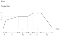
- the molded body undergoes a heat treatment step including a nitrification section (S 3 ) where the molded body is mounted in the sintering furnace and converted into silicon nitride (Si 3 N 4 ) and a sintering section (S 5 ) for sintering the nitrified molded body, and the heat treatment step may further include temperature increase sections (S 1 , S 2 ) before the nitrification section (S 3 ), a temperature increase section (S 4 ) between the nitrification section (S 3 ) and the sintering section (S 5 ), and a cooling section (S 6 ) after the sintering section (S 5 ).
- a heat treatment step including a nitrification section (S 3 ) where the molded body is mounted in the sintering furnace and converted into silicon nitride (Si 3 N 4 ) and a sintering section (S 5 ) for sintering the nitrified molded body
- the nitrification process of nitrifying the molded body into a silicon nitride molded body and the sintering process of sintering the nitrified molded body into a substrate are all performed in one heat treatment step.
- the conventional silicon nitride substrate is generally implemented by a two-step method of preparing silicon powder into silicon nitride powder and then using silicon nitride powder to manufacture a silicon nitride substrate.
- the cooling process and grinding process of the silicon nitride powder were further required until it is sintered after the preparation of the silicon nitride powder, and thus, the manufacturing time was long, and accordingly, the manufacturing cost was extended, and it was not suitable for mass production. Nevertheless, the reason for using such a two-step method is that silicon nitride powders having more uniform characteristics can be easily prepared when nitrifying on a small-sized powder, and this is advantageous in that the silicon nitride substrate also guarantees uniform characteristics.
- the present invention breaks away from the conventional two-step method that was inevitably adopted to implement a substrate with uniform characteristics, and by performing both of the nitrification process and the sintering process by a one-step method which is a heat treatment step, a silicon nitride substrate is manufactured, and accordingly, the present invention has been achieved by implementing a silicon nitride substrate with uniform characteristics while dramatically shortening the manufacturing time.
- the heat treatment step may be continuously performed from the nitrification section to the sintering section without interruption of the heat treatment.
- the molded body formed in the shape of the substrate since the molded body formed in the shape of the substrate is nitrified from the beginning and then sintered, it may not include a section for heat treatment at a temperature lower than the first temperature or cooling to a temperature lower than the first temperature between the nitrification section and the sintering section.
- the sheet-shaped molded body may be subjected to a heat treatment step in the state of the stacked body 100 in which several sheets of the molded body 1, 2 are stacked, as illustrated in (a) of FIG. 2 .
- the sheet-shaped molded body may be subjected to a heat treatment step in a state where two or more sheets are stacked.
- the stacked body 100 may perform a heat treatment step in a state of being disposed between BN plates 10.
- a release agent for example, BN powder, may be interposed between each of the stacked molded bodies 1, 2.
- the heat treatment step omits the movement of the stacked molded body due to changes in the furnace and is performed continuously without release and re-vacuum after vacuuming in the furnace not only has the advantages of not only reducing the manufacturing time, but also minimizing or preventing problems such as bending of the end of the silicon nitride substrate after the heat treatment step, and a decrease in curved strength and flatness.
- the prepared molded body may be heat-treated by varying a predetermined temperature increase rate or temperature increase rate before reaching the nitrification section (S 3 ) after being mounted in the furnace.
- a degreasing process for removing organic compounds such as an organic binder in the molded body may be performed.
- degreasing may be omitted.
- the degreasing process after the prepared molded body is mounted in a degreasing furnace, it may be degreased by heating from the heat treatment start temperature to 900°C while varying a predetermined temperature increase rate or temperature increase rate.
- the degreasing process may be performed under a known atmosphere, for example, an atmospheric atmosphere and/or a nitrogen atmosphere, and the specific atmosphere may be appropriately selected in consideration of the type and content of the organic binder used.
- the degreasing process is preferably performed under an atmospheric atmosphere in the temperature range of 450°C from the heat treatment start temperature, and in the temperature range of 450°C to 900°C, degreasing may be performed under a nitrogen atmosphere, which may be advantageous in minimizing or completely removing carbon components remaining in the molded body after the degreasing process.
- the heat treatment start temperature may be room temperature, for example, 20 to 25°C.
- the temperature may be raised at a rate of 2 to 8°C/min up to 450°C, and the temperature may be raised at a rate of 2 to 8°C/min from 450°C to 900°C, and the temperature increase rate to 450°C and the temperature increase rate from 450°C to 900°C may be the same or different from each other.
- secondary degreasing may be further performed at 900 to 1,000°C on the molded body subjected to the degreasing process after the degreasing process is performed.
- the temperature is preferably raised at a low rate of 1 to 10°C/min, and more preferably, 1 to 3°C/min, and the pressure may be preferably performed at 0.1 to 0.2 MPa, and more preferably, 0.14 to 0.17 MPa.
- the temperature may be raised at a slow rate while applying nitrogen gas at a predetermined pressure from a predetermined temperature (T 1 ), specifically, from a temperature of 1,000 ⁇ 20°C to a first temperature (T 2 ), and specifically, the temperature may be increased by applying nitrogen gas at a pressure of 0.1 to 0.2 MPa, and more preferably, 0.14 to 0.18 MPa.
- the temperature may be increased at a rate of 0.1 to 2.0°C/min, and more preferably, 0.5 to 1.0°C/min.
- the nitrogen gas pressure is less than 0.1 MPa, even after passing through the nitrification section (S 3 ), nitrification does not completely occur in the molded body, and thus, a non-nitrified portion may exist.
- the nitrogen gas pressure is more than 0.2 MPa, a phenomenon in which silicon is eluted may occur, and the thermal conductivity and mechanical strength of the substrate may be reduced.
- the temperature increase rate from 1,000 ⁇ 20°C to the first temperature is less than 0.1°C/min, the time required for the heat treatment step may be excessively extended.
- the temperature increase rate is more than 2.0°C/min, silicon is eluted, and it may be difficult to manufacture a completely nitrified substrate with silicon nitride.
- the temperature increase rate up to a temperature of 800°C or less, and the temperature increase conditions applied when nitrifying a general silicon substrate or silicon powder may be followed, and for example, the temperature may be increased at a rate of 4°C/min to 30°C/min.
- the temperature when the temperature is increased in this section, the temperature may be increased under an inert gas or nitrogen gas atmosphere.
- the nitrification process corresponding to the nitrification section (S 3 ), which is heat-treated at the first temperature (T 2 ), is performed while continuously applying heat to increase the temperature to the first temperature (T 2 ), and then applying nitrogen gas at a predetermined pressure.
- the first temperature (T 2 ) may be a predetermined temperature within the range of 1,300 to 1,500°C, and preferably, within the range of 1,400 to 1,500°C range. If the first temperature (T 2 ) is less than 1,300°C, nitrification may not occur uniformly. In addition, when the first temperature (T 2 ) is more than 1,500°C, the ⁇ crystal phase is rapidly formed, and thus, it may be difficult to densify the substrate.
- nitrogen gas may be applied at a pressure of 0.1 to 0.2 MPa, and more preferably, at a pressure of 0.14 to 0.18 MPa. If the pressure of nitrogen gas is less than 0.1 MPa, nitrification does not completely occur, and a non-nitrified portion may exist. In addition, if the pressure of nitrogen gas is more than 0.2 MPa, silicon may be eluted during the nitrification process, and the thermal conductivity and mechanical strength of the substrate may be reduced. In addition, the nitrification process may be performed over 2 to 10 hours, and more preferably, it may be performed for 1 to 4 hours. Meanwhile, the time of the nitrification process may be appropriately adjusted according to the first temperature (T 2 ).
- the pressure of nitrogen gas applied from the 1,000 ⁇ 20°C to the first temperature may be lower than the pressure of nitrogen gas applied in the nitrification section, and through this, the nitrogen gas is more uniformly nitrified, and it may be advantageous to implement a substrate having excellent appearance and mechanical strength.
- the heat treatment may be performed at a predetermined temperature increase rate up to the second temperature (T 3 ) at which the sintering process is performed after the nitrification process.
- the temperature may be increased at a slow rate by applying nitrogen gas at a predetermined pressure from the first temperature (T 2 ) to the second temperature (T 3 ), and specifically, the temperature may be increased at a rate of 0.1 to 10.0°C/min under nitrogen gas at a pressure of 0.1 MPa to 1.0 MPa. If the nitrogen gas pressure is less than 0.1 MPa, it may be difficult to suppress the decomposition of silicon nitride.
- the pressure of nitrogen gas is more than 1.0 MPa
- the pressure resistance of the furnace may be problematic.
- the temperature increase rate from the first temperature (T 2 ) is less than 0.1°C/min, the time required for the heat treatment step may be excessively extended.
- the temperature increase rate is more than 10.0°C/min, a rapid transition to the beta phase occurs, and as a result, crystal control may not be easy, because beta phase crystals grow unevenly, and the implemented substrate may have difficulty in having the desired physical properties.
- the temperature increase section from the first temperature (T 2 ) to the second temperature (T 3 ) may be performed by subdividing into two sections, through which a substrate having more excellent physical properties may be manufactured.
- it may further include a first contraction section which is heated at a rate of 0.1 to 10.0°C/min under a nitrogen gas pressure of 0.15 to 0.30 MPa from the first temperature (T 2 ) to 1,700 ⁇ 20°C, and a second contraction section which is heated from 1,700 ⁇ 20°C to the second temperature (T 3 ) at a rate of 1 to 10°C/min under a nitrogen gas pressure of 0.80 to 0.98 MPa between the nitrification section and the sintering section.
- the pressure of nitrogen gas may be 0.15 to 0.3 MPa in the first contraction section, and the pressure of nitrogen gas may be 0.8 to 0.9 MPa in the second contraction section.
- the first contraction section may be performed at a temperature increase rate of 0.1 to 10°C/min, and more preferably, 0.1 to 2°C/min.
- the temperature may be increased at 1 to 10°C/min, and more preferably, at 1 to 5°C/min, and through this, it may be easy to achieve the objects of the present invention.
- the second temperature (T 3 ) may be selected within the range of 1,700 to 1,900°C. If the temperature is less than 1,700° C, the molded body may not be sufficiently densified. In addition, if the temperature is more than 1,900°C, the overgrowth and/or non-uniform growth of particles is concerned, and the mechanical strength of the implemented substrate may be reduced.
- the sintering time may be adjusted depending on the above-described second temperature (T 3 ) range, and when the second temperature (T 3 ) is low, the sintering may be performed for a long period of time, and conversely, when the second temperature (T 3 ) is high, relatively, the sintering may be performed for a short period of time compared to the sintering time under low temperature conditions.
- the sintering may be performed, for example, for 2 to 10 hours, and more preferably, for 4 to 8 hours, which is advantageous to achieve the objects of the present invention.
- the sintering process may also be performed under a nitrogen gas atmosphere, and in this case, the pressure of nitrogen gas pressure may be an atmospheric condition used for sintering the silicon nitride molded body.
- nitrogen gas may be applied at a pressure of 0.1 MPa or more, and more preferably, it may be sintered under a nitrogen gas pressure of 0.9 to 1.0 MPa, and more preferably, 0.9 to 0.98 MPa, which may be more advantageous for implementing a high-quality silicon nitride substrate.
- the substrate which has undergone the sintering section (S-5) of the heat treatment step may be further subjected to a cooling section (S6), and the cooling section (S6) may follow the cooling conditions after sintering of the conventional silicon nitride substrate, and the present invention is not particularly limited thereto.
- the silicon nitride substrate implemented by the above-described manufacturing method it is possible to implement a silicon nitride substrate having a thermal conductivity of 75 W/mK or more, preferably, 80 W/mK or more, and more preferably, 90 W/mK or more, and a 3-point bending strength of 650 MPa or more, preferably, 680 MPa or more, more preferably, 700 MPa or more, and still more preferably, 750 MPa or more.
- the substrate may have improved mechanical strength and thermal conductivity as it preferably includes silicon at 6 wt.% or less, more preferably, 4 wt.% or less, and still more preferably, 0 wt.% or less.
- a polycrystalline silicon scrap (purity 99.99%, resistivity 1 Qcm) derived from a jig for semiconductor process was dry-ground using a jet mill to prepare metallic silicon powder having an average particle diameter of 4 ⁇ m.
- a ceramic composition was prepared by mixing the same with 3 mol% of yttrium oxide having an average particle diameter of 0.5 ⁇ m and 5 mol% of magnesium oxide having an average particle diameter of 0.5 ⁇ m. 100 parts by weight of the prepared ceramic composition was mixed with 80 parts by weight of ethanol as a solvent and 10 parts by weight of polyvinyl butyral as an organic binder to prepare a slurry for manufacturing a substrate, which was manufactured as a sheet-shaped molded body by using the tape casting method.
- the temperature was increased at a temperature increase rate of 5°C/min at a pressure of 0.15 Mpa up to 900°C, and at a rate of 1.2°C/min from 900°C to 1,000°C. Thereafter, after setting the temperature increase rate at 0.5°C/min from 1,000°C to a first temperature of 1,460°C at a nitrogen gas pressure of 0.15MPa, a nitrified substrate was obtained by heat treatment at the first temperature of 1,460°C for 2 hours at a nitrogen gas pressure of 0.17 MPa.
- the temperature was increased to a second temperature of 1,850°C at a temperature increase rate of 4°C/min under a nitrogen gas pressure of 0.9 MPa, and it was sintered at 1,850°C for 5 hours under a nitrogen gas pressure of 0.9MPa to manufacture a silicon nitride substrate with a final thickness of 170 ⁇ m.
- Silicon nitride substrates as shown in Tables 1 to 3 were manufactured in the same manner as in Example 1, except that the first temperature, the second temperature, the nitrification section pressure, the yttrium oxide content and the magnesium oxide content were changed.
- P is the maximum load
- L is the length of the specimen
- w is the width of the specimen
- t is the thickness of the specimen.
- thermal conductivity k ⁇ ⁇ ⁇ ⁇ Cp
- ⁇ is the thermal diffusion coefficient (mm 2 /S)
- ⁇ is the density (g/cm 3 )
- Cp is the heat capacity (J/(kgK)).
- the surface state after sintering was evaluated by confirming the degree of reaction of the sintered body as a phenomenon in which Si is melted and eluted without being completely nitrified (provided that in specimens where dissolution has occurred, since it is not possible to manufacture specimens for which the thermal conductivity and 3-point bending strength can be measured, it is impossible to measure the physical properties.
- Example 1 to 3 Example 5, Example 7 and Example 9, which satisfied all of the first temperature, second temperature, nitrification section pressure, yttrium oxide content and magnesium oxide content according to the present invention, had excellent mechanical strength and thermal conductivity and simultaneously exhibited the effect that the surface state after sintering was good at the same time, compared to Example 4, Example 6, Example 8, Examples 10 to 12 and Comparative Examples 1 to 4, which did not satisfy any one of the above.
Landscapes
- Chemical & Material Sciences (AREA)
- Engineering & Computer Science (AREA)
- Ceramic Engineering (AREA)
- Manufacturing & Machinery (AREA)
- Materials Engineering (AREA)
- Structural Engineering (AREA)
- Organic Chemistry (AREA)
- Chemical Kinetics & Catalysis (AREA)
- Inorganic Chemistry (AREA)
- Ceramic Products (AREA)
Applications Claiming Priority (2)
| Application Number | Priority Date | Filing Date | Title |
|---|---|---|---|
| KR20210058595 | 2021-05-06 | ||
| PCT/KR2022/006365 WO2022235067A1 (ko) | 2021-05-06 | 2022-05-03 | 질화규소 기판 제조방법 및 이를 통해 제조된 질화규소 기판 |
Publications (1)
| Publication Number | Publication Date |
|---|---|
| EP4335834A1 true EP4335834A1 (de) | 2024-03-13 |
Family
ID=83932861
Family Applications (1)
| Application Number | Title | Priority Date | Filing Date |
|---|---|---|---|
| EP22799110.6A Pending EP4335834A1 (de) | 2021-05-06 | 2022-05-03 | Verfahren zur herstellung eines siliciumnitridsubstrats und dadurch hergestelltes siliciumnitridsubstrat |
Country Status (6)
| Country | Link |
|---|---|
| US (1) | US20240116822A1 (de) |
| EP (1) | EP4335834A1 (de) |
| JP (1) | JP2024516436A (de) |
| KR (1) | KR20220151559A (de) |
| CN (1) | CN117242044A (de) |
| WO (1) | WO2022235067A1 (de) |
Family Cites Families (5)
| Publication number | Priority date | Publication date | Assignee | Title |
|---|---|---|---|---|
| JPH1179872A (ja) * | 1997-09-03 | 1999-03-23 | Sumitomo Electric Ind Ltd | メタライズ窒化ケイ素系セラミックス、その製造方法及びその製造に用いるメタライズ組成物 |
| JP5673106B2 (ja) * | 2009-01-13 | 2015-02-18 | 日立金属株式会社 | 窒化珪素基板の製造方法、窒化珪素基板、窒化珪素回路基板および半導体モジュール |
| WO2015152292A1 (ja) * | 2014-03-31 | 2015-10-08 | 日本ファインセラミックス株式会社 | 窒化ケイ素基板の製造方法 |
| KR20170135105A (ko) * | 2016-05-30 | 2017-12-08 | 한국세라믹기술원 | 시트형 질화규소 기판의 제조방법 |
| KR20210035356A (ko) * | 2019-09-20 | 2021-04-01 | 오씨아이 주식회사 | 질화규소 기판의 제조 방법 |
-
2022
- 2022-05-03 EP EP22799110.6A patent/EP4335834A1/de active Pending
- 2022-05-03 CN CN202280032652.6A patent/CN117242044A/zh active Pending
- 2022-05-03 JP JP2023566929A patent/JP2024516436A/ja active Pending
- 2022-05-03 WO PCT/KR2022/006365 patent/WO2022235067A1/ko active Application Filing
- 2022-05-03 US US18/289,372 patent/US20240116822A1/en active Pending
- 2022-05-04 KR KR1020220055143A patent/KR20220151559A/ko not_active Application Discontinuation
Also Published As
| Publication number | Publication date |
|---|---|
| WO2022235067A1 (ko) | 2022-11-10 |
| JP2024516436A (ja) | 2024-04-15 |
| KR20220151559A (ko) | 2022-11-15 |
| CN117242044A (zh) | 2023-12-15 |
| US20240116822A1 (en) | 2024-04-11 |
Similar Documents
| Publication | Publication Date | Title |
|---|---|---|
| EP1666434B1 (de) | Sehr wärmeleitfähiger siliciumnitrid-sinterkörper und siliciumnitrid-bauelement | |
| EP0589997B1 (de) | Gesintertes silicumnitrid von hoher zähigkeit und festigkeit | |
| JPS6128627B2 (de) | ||
| KR0168302B1 (ko) | 질화 알루미늄 소결체 및 그의 제조방법 | |
| EP4335834A1 (de) | Verfahren zur herstellung eines siliciumnitridsubstrats und dadurch hergestelltes siliciumnitridsubstrat | |
| JP4556162B2 (ja) | 窒化珪素質焼結体及びその製造方法、並びにそれを用いた回路基板 | |
| JP3537241B2 (ja) | 窒化珪素焼結体の製造方法 | |
| EP0963360B1 (de) | Gasdruckgesintertes siliciumnitrid mit hoher festigkeit und bruchspannungsbeständigkeit | |
| KR20190023485A (ko) | 질화알루미늄 소결체 및 이의 제조방법 | |
| KR101436468B1 (ko) | 고강도 질화알루미늄(AlN) 소결체 및 이의 저온 소결방법 | |
| EP4310051A1 (de) | Verfahren zur herstellung von siliciumnitridpulver zur herstellung eines substrats und dadurch hergestelltes siliciumnitridpulver | |
| JP3152790B2 (ja) | 窒化珪素質焼結体の製造方法 | |
| KR20230109114A (ko) | 정전 척 히터 소결체 제조용 세라믹 조성물 및 이를 이용한 정전 척 히터용 질화규소 소결체 제조방법 | |
| JP2001206774A (ja) | 窒化珪素質焼結体 | |
| JPH04270173A (ja) | SiC焼結体 | |
| JP3929335B2 (ja) | 窒化アルミニウム焼結体およびその製造方法 | |
| JP2001354479A (ja) | 窒化アルミニウム焼結体およびその製造方法 | |
| JPH11322438A (ja) | 高熱伝導性窒化ケイ素質焼結体及びその製造方法 | |
| JP3124867B2 (ja) | 窒化珪素質焼結体及びその製造方法 | |
| JPH05330919A (ja) | 窒化珪素質焼結体及びその製造方法 | |
| JP3216973B2 (ja) | 窒化珪素質焼結体及びその製造方法 | |
| JP3124882B2 (ja) | 窒化ケイ素質焼結体およびその製造方法 | |
| JP3034099B2 (ja) | 窒化珪素質焼結体およびその製造方法 | |
| JP2783702B2 (ja) | 窒化珪素質焼結体 | |
| JP2700786B2 (ja) | 高温高強度窒化珪素質焼結体及びその製造方法 |
Legal Events
| Date | Code | Title | Description |
|---|---|---|---|
| STAA | Information on the status of an ep patent application or granted ep patent |
Free format text: STATUS: THE INTERNATIONAL PUBLICATION HAS BEEN MADE |
|
| PUAI | Public reference made under article 153(3) epc to a published international application that has entered the european phase |
Free format text: ORIGINAL CODE: 0009012 |
|
| STAA | Information on the status of an ep patent application or granted ep patent |
Free format text: STATUS: REQUEST FOR EXAMINATION WAS MADE |
|
| 17P | Request for examination filed |
Effective date: 20231108 |
|
| AK | Designated contracting states |
Kind code of ref document: A1 Designated state(s): AL AT BE BG CH CY CZ DE DK EE ES FI FR GB GR HR HU IE IS IT LI LT LU LV MC MK MT NL NO PL PT RO RS SE SI SK SM TR |