EP4335253B1 - Breitbandige mikrowellenfensteranordnung - Google Patents
Breitbandige mikrowellenfensteranordnung Download PDFInfo
- Publication number
- EP4335253B1 EP4335253B1 EP22727151.7A EP22727151A EP4335253B1 EP 4335253 B1 EP4335253 B1 EP 4335253B1 EP 22727151 A EP22727151 A EP 22727151A EP 4335253 B1 EP4335253 B1 EP 4335253B1
- Authority
- EP
- European Patent Office
- Prior art keywords
- microwave window
- microwave
- window assembly
- broadband
- rectangular
- Prior art date
- Legal status (The legal status is an assumption and is not a legal conclusion. Google has not performed a legal analysis and makes no representation as to the accuracy of the status listed.)
- Active
Links
Images


Classifications
-
- H—ELECTRICITY
- H01—ELECTRIC ELEMENTS
- H01P—WAVEGUIDES; RESONATORS, LINES, OR OTHER DEVICES OF THE WAVEGUIDE TYPE
- H01P1/00—Auxiliary devices
- H01P1/08—Dielectric windows
-
- H—ELECTRICITY
- H05—ELECTRIC TECHNIQUES NOT OTHERWISE PROVIDED FOR
- H05B—ELECTRIC HEATING; ELECTRIC LIGHT SOURCES NOT OTHERWISE PROVIDED FOR; CIRCUIT ARRANGEMENTS FOR ELECTRIC LIGHT SOURCES, IN GENERAL
- H05B6/00—Heating by electric, magnetic or electromagnetic fields
- H05B6/64—Heating using microwaves
- H05B6/70—Feed lines
- H05B6/707—Feed lines using waveguides
Definitions
- the present invention relates to a broadband microwave window assembly comprising a Brewster waveguide window, a single mode microwave reactor system comprising a waveguide with a Brewster waveguide window and a method to produce a waveguide with a Brewster waveguide window.
- Microwaves are widely used in modern technology.
- microwave windows may be arranged so as to follow the Brewster principle.
- solutions employing Brewster angle in general require a plane wave or a quasi -plane wave, the circular TE01 mode or the Gaussian LP01 or HE11 mode.
- these solutions requires transformation of the fundamental mode into the above mentioned modes in order to allow for transmittal within the window. This generally results in substantial power reduction and requires expensive and complex mode converters.
- a broadband microwave window assembly able to couple high frequency, high power microwave radiation within a waveguide without overheating, significant build-up of trapped modes, or reflection of incident power, would be advantageous.
- US 2 894 228 A discloses a broadband microwave window assembly comprising a rectangular waveguide, a microwave window pane inclined with respect to the propagation direction of microwaves in accordance with the Brewster angle, the microwave window pane located within the rectangular waveguide, and inductive irises located around the microwave window pane, matching out the capacitive loading of the rectangular waveguide.
- An object of the present invention is to provide a broadband microwave window assembly able to couple high frequency, high power microwave radiation within the waveguide without overheating, significant build-up of trapped modes, or reflection of incident power.
- An object of the present invention may also be seen as to provide an alternative to the prior art.
- the invention relates to a distributed waveguide window in fundamental mode rectangular waveguides.
- the window broadband microwave window assembly may thus be seen as a single mode broadband microwave window assembly, as only the fundamental mode is present and propagates in the rectangular waveguide.
- the waveguide window pane is positioned at the Brewster angle inside the rectangular waveguide.
- the Brewster angle is an angle of incidence at which the microwaves travelling along waveguides having a particular mode are perfectly transmitted through a dielectric surface, with no reflection.
- Solutions employing Brewster angle in general require a plane wave or a quasi - plane wave, the circular TE01 mode or the Gaussian LP01 or HE11 mode.
- the microwave window pane width has been adjusted by employing inductive irises to overcome the non-plane wave condition within the rectangular waveguide and to match out the capacitive loading of the waveguide.
- the microwave window pane inclined with respect to the propagation direction of microwaves in accordance with the Brewster angle may be also referred to as a Brewster window that is a transparent plate oriented at Brewster's angle such that parasitic reflection losses are minimized.
- the pane which is transparent to microwaves, has plane-parallel, flat main surfaces.
- the plane formed by the propagation direction and the normal to the pane, is in the same plane as the polarisation direction of the microwaves.
- the inductive irises are symmetrical irises located around, such as surrounding the microwave window pane or at least at the edges, such as at least at two edges of the microwave window pane.
- the microwave window pane may be viewed as a distributed microwave window assembly.
- the presence of inductive irises allows for cancellation of the capacitive loading of the rectangular waveguide due to the microwave window pane. In this way the microwave window assembly may be considered as broadband.
- Electromagnetic waves can travel along waveguides using a number of different modes.
- transverse electric (TE) and transverse magnetic (TM) waves there two types of waves in a hollow waveguide with only one conductor: transverse electric (TE) and transverse magnetic (TM) waves.
- Transverse electric (TE) modes are characterized by having only a magnetic field along the direction of propagation no electric field in the direction of propagation.
- TE modes have the electric vector (E) being always perpendicular to the direction of propagation.
- the fundamental mode of a waveguide is the mode that has the lowest cut-off frequency.
- the TE 10 mode is the fundamental mode.
- the rectangular waveguide may be a standard 3.4 inches waveguide such as a WR-340 waveguide. However, rectangular waveguide having different dimensions may be used by applying opportune adjustments.
- the rectangular waveguide may thus operate in its fundamental TE 10 mode at a frequency of 2.45GHz. However, operation in other modes or at different frequency may be used by applying opportune adjustments.
- the microwave window pane comprises ceramic materials, such as alumina ceramic materials.
- the microwave window pane may be constructed of a special low loss Alumina ceramic material.
- the material can be of different types with other dielectric properties which, in turn, would result in adjustments of the Brewster angle and of the irises size.
- the low loss Alumina ceramic material may comprise Al 2 O 3 in a percentage between 92% and 99.9%, such as 99.8% of Al 2 O 3 .
- the low loss Alumina ceramic material may also comprise other elements in traces, such as Si in a concentration between 10 and 1000 ppm, such as 60 ppm, Na in a concentration between 1 and 250 ppm, such as 10 ppm, FE in a concentration between 1 and 100 ppm, such as 60 ppm, Mg in a concentration between 1 and 1000 ppm, such as 250 ppm.
- the low loss Alumina ceramic material may have a grain size between 0.5 and 35 ⁇ m and average grain size of 6 ⁇ m.
- the ceramic materials are low dielectric loss ceramic materials.
- Low dielectric loss is referred to as lower then 10 -3 , such as lower than 10 -4 as measured according to ASTM-D150.
- Low-loss dielectric materials may be used to produce the microwave window pane according to the invention.
- microwave ceramics These may also be referred to as oxide ceramics or microwave ceramics. Properties of microwave ceramics depend on several parameters including their composition, the purity of starting materials, processing conditions and their ultimate densification/porosity.
- Optimal low-loss dielectric material for microwave ceramics may have optimised value of relative permittivity or dielectric constant ( ⁇ r), low dielectric loss (loss tangent, tan ⁇ ), low temperature coefficient of resonant frequency ( ⁇ f) and high shear/tensile strength and appropriate Young's Modulus.
- Tantalates, niobates, titanates, silicates, tungstates, molybdanates, vanadates or tellurates based on alkali earth metal and rare earths may also be used as low dielectric loss ceramic materials.
- low dielectric loss material may be used.
- high temperature glass ceramic such as Macor ®
- aluminium oxynitride such as ALON ®
- boron nitride quartz
- fused silica diamond
- sapphire and beryllium oxide may be used as low dielectric loss ceramic materials according to the invention.
- the ceramic materials have a dielectric constant between 3 and 12, such as between 9 and 10.
- the ceramic materials of the microwave window pane may have a dielectric constant between 9.7 and 9.9, such as 9.8.
- the angle of the window pane relative to the plane of the waveguide broad wall should decrease when the dielectric constant increases.
- slightly higher value of dielectric constant such as between 9.7 and 9.9 requires a smaller angle, i.e. a longer window pane, which in turn allows for a better distribution of the power hitting the window pane surface.
- the microwave window pane has a thickness lower than 10 % of the microwave wavelength propagating within the rectangular waveguide when in operation.
- a microwave window pane with a thickness lower than 10 % of the microwave wavelength propagating within the rectangular waveguide when in operation has the advantage of preventing ghost-modes and wave propagation through the microwave window pane.
- a microwave window pane with a thickness lower than 10 % of the microwave wavelength propagating within the rectangular waveguide has shown to be the maximum acceptable thickness to prevent ghost-modes, and wave propagation through the microwave window pane.
- a microwave window pane having a thickness lower than or equal to 3 mm has shown to prevent ghost-modes and wave propagation through the microwave window pane.
- the broadband microwave window assembly of the invention has the advantage of being able to be used with rectangular waveguides to couple high frequency, high power microwave radiation within the waveguide without overheating, significant build-up of trapped modes, or reflection of incident power.
- cooling means may be advantageous.
- the broadband microwave window assembly further comprises means for cooling said microwave window pane.
- the advantage of using means for cooling is that these lower the stress on the window pane and reduce possible variations of the properties of the window pane induced by temperature variations.
- Means of cooling allows for temperature reduction within the broadband microwave window assembly.
- Means for cooling may be channels having at least part of their external surfaces in contact with the heat transferring surfaces of surrounding the microwave window pane.
- the means for cooling are or comprise fluid heat exchangers.
- the cooling fluid may be a liquid or a gas.
- a counter current heat exchanger between two liquids may be used so provide cooling to the microwave window pane.
- the fluid heat exchangers are or comprise water cooling channels.
- the fluids heat exchangers may comprise further means for cooling.
- the fluid heat exchangers may be or comprise air cooling fins.
- This use of means for cooling produced a broadband microwave window assembly able to handle 10KW CW power without significant temperature rise of the microwave window pane.
- the broadband microwave window assembly further comprises means for inspecting the temperature of the microwave window pane.
- the means for inspecting the temperature of the microwave window pane may be a means for inspecting the temperature of or at the microwave window pane.
- the means for inspecting the temperature of the microwave window pane are or comprise an Infra-Red (IR) sensor within a thermal camera inspection tube monitoring the temperature of the microwave window pane.
- IR Infra-Red
- the presence of an IR sensor within a thermal camera allows for an optimal temperature evaluation of the temperature of the microwave window pane.
- a circular tube may be inserted into the broadband microwave window assembly.
- the tube may be designed with a diameter small enough to be at cutoff at 2.45 GHz. This makes it possible to insert an IR sensor into the tube to monitor the microwave window pane temperature.
- the inductive irises are matched to the frequency and the characteristics of the ceramic materials, so that the capacitive impedance of the window pane and the inductive impedance of the irises cancel out.
- the inductive irises are placed within the magnetic field and are effectively obstructions within the window pane that provide inductive elements.
- the irises place a shunt inductance across the window pane that is proportional to the size of irises.
- the inductive irises of the invention are matched to the frequency of the ceramic material of the window pane so that the inductive impedance of the irises cancel out the capacitance impedance of the window pane.
- the dimension of the irises may depend on the frequency on the material used and on other parameters.
- the cross section of the irises may be 10 mm x 4.35 mm.
- Single mode or single dominating mode microwave reactors is herein defined as a reactor in which microwaves propagates substantially in a single mode.
- the single mode or single dominating mode of propagation maybe a transverse electric (TE) mode.
- TE transverse electric
- the broadband microwave window assembly of the invention may be used in combination with a single mode or single dominating mode microwave flow reactor supressing the propagation of over-modes, so that the material to be processed receive a more even distribution of Electric field.
- the broadband microwave window assembly of the invention in combination with a single mode or single dominating mode microwave flow reactor provides a single mode microwave reactor system able to produce a homogenous electromagnetic field distribution within the reactor.
- one application of the broadband microwave window assembly may be within microwave-heating applications for environmental and medical uses, microwave drying processing, food processing, ink and paint as well as in wood treatments and agricultural uses.
- a further application of the broadband microwave window assembly may also be within radar and telecom applications, microwave chemistry and material processing related to inorganic or organic synthesis, for biochemistry reaction, polymer related processes as well for catalytic chemistry processing.
- the broadband microwave window assembly eliminates high voltage buildup in the vicinity of the microwave window pane, thereby not accelerating charged dust particles onto the microwave window pane and also not accreting particles which in turn could lead to an electrical breakdown of the microwave window pane and/or of the broadband microwave window assembly.
- the broadband microwave window assembly may be used for several applications which require high power transmission, e.g. medical or other high power physics applications.
- the invention in a third aspect, relates to a method of producing a broadband microwave window assembly according to the first aspect of the invention, the method comprising: assembling identical half housing of the broadband microwave window assembly; fastening the housing.
- Fastening may be accomplished by welding, screwing or other fastening technique.
- the broadband microwave window assembly may be made out of four aluminium parts assembled in the middle of the rectangular waveguide broad wall, and at the microwave window pane position, along the microwave window pane, respectively.
- the broadband microwave window assembly may be made out of titanium and may be produced through additive manufacturing or 3D printing processes.
- This assembling is determined by the fact that the surface currents in the fundamental mode originate from the middle of the waveguide broad wall. Therefore there is no current flow at this assembly position, making a mechanical split of the structure possible.
- the broadband microwave window assembly comprising a Brewster waveguide window, a single mode microwave reactor system comprising a waveguide with a Brewster waveguide window and a method to produce a waveguide with a Brewster waveguide window
- the figures show one way of implementing the present invention and are not to be construed as being limiting to other possible embodiments falling within the scope of the attached claim set.
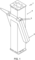
- Figure 1 is a schematic illustration of a broadband microwave window assembly 1 showing some of the relevant features of the assembly.
- Figure 1 shows the rectangular waveguide 4 and the location 2 of the microwave window pane (not shown).
- Figure 1 further shows the presence of means for cooling, i.e. cooling channels 3.
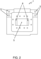
- Figure 2 is a top view of a broadband microwave window assembly 1.
- microwave window pane 5 is shown although it cannot be appreciated the inclination with respect to the propagation direction of microwaves in accordance with the Brewster angle.
- inductive irises 6 located on the sides of the around the microwave window pane 5.
- FIG. 1 further shows the presence of the cooling channels 3.
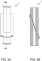
- Figure 3B is a further illustration of a cross section of a broadband microwave window assembly 1.
- Figure 3A is a side view indicating the position of the cross section of figure 3B of a broadband microwave window assembly 1.
- Figure 4B is a further illustration of a cross section of a broadband microwave window assembly 1.
- Figure 4A is a side view indicating the position of the cross section of figure 4B of a broadband microwave window assembly 1.
- FIG. 5 is a schematic illustration of a broadband microwave window assembly 7 showing the presence of cooling channels 9.
- Figure 5 shows also the location of the inspection tube 8 for inserting an IR sensor within a thermal camera allowing for an optimal temperature evaluation of the temperature of the microwave window pane.
- Figure 6 is a cross section of a broadband microwave window assembly 7 showing inductive irises 10 at the edges of the microwave window pane 11.
- Figure 7 is a cross sectional view of the E-field 13 in the direction of propagation of the microwaves inside the broadband microwave window assembly.
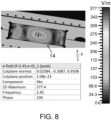
- Figure 8 is a cross sectional view of the E-field 14 orthogonal to the direction of propagation of the microwaves inside the microwave window pane of the broadband microwave window assembly.
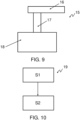
- Figure 9 is a schematic illustration of the single dominating mode microwave reactor system 15.
- the single mode microwave reactor system 15 comprises a single mode microwave reactor 18, a microwave generator 16 and a broadband microwave window assembly 17 connecting the microwave generator 16 to the single mode microwave reactor 18.
- Figure 10 shows a flow chart 19 of the method of producing a broadband microwave window assembly, the method comprising the steps of
Landscapes
- Physics & Mathematics (AREA)
- Electromagnetism (AREA)
- Constitution Of High-Frequency Heating (AREA)
- Waveguides (AREA)
- Control Of Motors That Do Not Use Commutators (AREA)
- Lasers (AREA)
- Waveguide Connection Structure (AREA)
Claims (12)
- Breitbandige Mikrowellenfensteranordnung (1), die so konfiguriert ist, dass sie in der Grund-TE10-Wellenleiter-Mode arbeitet, wobei die breitbandige Mikrowellenfensteranordnung (1) umfasst:- einen rechteckigen Wellenleiter (4);- eine rechteckige Mikrowellenfensterscheibe (5), die in Bezug auf die Ausbreitungsrichtung von Mikrowellen in Übereinstimmung mit dem Brewster-Winkel geneigt ist, wobei sich die rechteckige Mikrowellenfensterscheibe (5) innerhalb des rechteckigen Wellenleiters (4) befindet, wobei die rechteckige Mikrowellenfensterscheibe (5) eine Dicke von weniger als 10 % der Mikrowellenwellenlänge aufweist;- induktive Blenden (6), die sich um die rechteckige Mikrowellenfensterscheibe (5) herum befinden, wodurch die kapazitive Belastung des rechteckigen Wellenleiters (4) ausgeglichen wird.
- Breitbandige Mikrowellenfensteranordnung nach Anspruch 1, wobei die rechteckige Mikrowellenfensterscheibe (5) keramische Materialien, wie zum Beispiel Aluminiumoxid-Keramikmaterialien, umfasst.
- Breitbandige Mikrowellenfensteranordnung nach Anspruch 2, wobei die keramischen Materialien keramische Materialien mit geringem dielektrischen Verlust sind.
- Breitbandige Mikrowellenfensteranordnung nach einem der vorstehenden Ansprüche 2 - 3, wobei die keramischen Materialien eine Dielektrizitätskonstante zwischen 3 und 12 aufweisen.
- Breitbandige Mikrowellenfensteranordnung nach einem der vorstehenden Ansprüche 1 - 4, die weiter Mittel zum Kühlen der rechteckigen Mikrowellenfensterscheibe umfasst.
- Breitbandige Mikrowellenfensteranordnung nach Anspruch 5, wobei die Mittel zum Kühlen Fluid-Wärmetauscher sind oder umfassen.
- Breitbandige Mikrowellenfensteranordnung nach Anspruch 6, wobei die Fluid-Wärmetauscher Wasserkühlkanäle (3) sind oder diese umfassen.
- Breitbandige Mikrowellenfensteranordnung nach Anspruch 7, wobei die Fluid-Wärmetauscher Luftkühlrippen sind oder umfassen.
- Breitbandige Mikrowellenfensteranordnung nach einem der vorstehenden Ansprüche 1 - 8, die weiter Mittel zum Überprüfen der Temperatur der rechteckigen Mikrowellenfensterscheibe umfasst.
- Breitbandige Mikrowellenfensteranordnung nach Anspruch 9, wobei die Mittel zum Überprüfen der Temperatur der rechteckigen Mikrowellenfensterscheibe ein Infrarotsensor innerhalb einer Wärmekamera-Überprüfungsröhre sind oder umfassen, die die Temperatur der rechteckigen Mikrowellenfensterscheibe überwacht.
- Breitbandige Mikrowellenfensteranordnung nach einem der vorstehenden Ansprüche 2 - 10, wobei die induktiven Blenden (6) an die Frequenz und die Eigenschaften der keramischen Materialien angepasst sind, wodurch sich die kapazitive Impedanz der rechteckigen Mikrowellenfensterscheibe (5) und die induktive Impedanz der induktiven Blenden (6) aufheben.
- Einmoden-Mikrowellen-Reaktorsystem (15), das umfasst:- einen Einmoden-Mikrowellenreaktor (18), der eine Reaktorkammer und Mittel zum Übertragen von Einmoden-Mikrowellen in eine mit der Reaktorkammer verbundene Reaktorkammer umfasst;- einen Mikrowellengenerator (16);- eine breitbandige Mikrowellenfensteranordnung (1, 17) nach einem der vorstehenden Ansprüche 1 - 11, die den Mikrowellengenerator mit dem Einmoden-Mikrowellenreaktor verbindet.
Priority Applications (1)
| Application Number | Priority Date | Filing Date | Title |
|---|---|---|---|
| HRP20250510TT HRP20250510T1 (hr) | 2021-05-05 | 2022-05-04 | Širokopojasni sklop prozora mikrovalne pećnice |
Applications Claiming Priority (2)
| Application Number | Priority Date | Filing Date | Title |
|---|---|---|---|
| DKPA202170211 | 2021-05-05 | ||
| PCT/EP2022/061988 WO2022233940A1 (en) | 2021-05-05 | 2022-05-04 | A broadband microwave window assembly |
Publications (3)
| Publication Number | Publication Date |
|---|---|
| EP4335253A1 EP4335253A1 (de) | 2024-03-13 |
| EP4335253B1 true EP4335253B1 (de) | 2025-02-26 |
| EP4335253C0 EP4335253C0 (de) | 2025-02-26 |
Family
ID=81877852
Family Applications (1)
| Application Number | Title | Priority Date | Filing Date |
|---|---|---|---|
| EP22727151.7A Active EP4335253B1 (de) | 2021-05-05 | 2022-05-04 | Breitbandige mikrowellenfensteranordnung |
Country Status (10)
| Country | Link |
|---|---|
| US (1) | US20240222828A1 (de) |
| EP (1) | EP4335253B1 (de) |
| JP (1) | JP2024517237A (de) |
| AU (1) | AU2022270916A1 (de) |
| CA (1) | CA3218200A1 (de) |
| ES (1) | ES3026233T3 (de) |
| HR (1) | HRP20250510T1 (de) |
| HU (1) | HUE071267T2 (de) |
| PL (1) | PL4335253T3 (de) |
| WO (1) | WO2022233940A1 (de) |
Families Citing this family (1)
| Publication number | Priority date | Publication date | Assignee | Title |
|---|---|---|---|---|
| US20240222828A1 (en) * | 2021-05-05 | 2024-07-04 | Organic Fuel Technology A/S | A broadband microwave window assembly |
Family Cites Families (20)
| Publication number | Priority date | Publication date | Assignee | Title |
|---|---|---|---|---|
| US2412446A (en) * | 1942-10-31 | 1946-12-10 | Gen Electric | Ultra high frequency system |
| US2706275A (en) * | 1946-01-21 | 1955-04-12 | Jr Melville Clark | Transmission line windows having high voltage breakdown characteristic |
| US2637776A (en) * | 1948-04-20 | 1953-05-05 | Bell Telephone Labor Inc | Sealed wave guide window |
| US2894228A (en) * | 1953-11-02 | 1959-07-07 | Varian Associates | Radio frequency window |
| US2847647A (en) * | 1956-08-09 | 1958-08-12 | Gen Precision Lab Inc | Microwave modulator |
| US3039068A (en) * | 1960-08-05 | 1962-06-12 | Gen Electric | Transmission line windows |
| US3857112A (en) * | 1973-11-02 | 1974-12-24 | Gte Sylvania Inc | Broadband quarter-wave plate assembly |
| US4352077A (en) * | 1979-05-18 | 1982-09-28 | Varian Associates, Inc. | Ridged waveguide window assembly |
| FR2472279A1 (fr) * | 1979-12-18 | 1981-06-26 | Thomson Csf | Fenetre hyperfrequence et guide d'onde comportant une telle fenetre |
| FR2558306B1 (fr) * | 1984-01-17 | 1988-01-22 | Thomson Csf | Fenetre circulaire pour guide d'onde hyperfrequence |
| EP0465845A3 (en) * | 1990-06-15 | 1992-06-10 | Asea Brown Boveri Ag | Microwave window |
| TW385623B (en) * | 1997-10-20 | 2000-03-21 | Sumitomo Metal Ind | Apparatus and method for microwave plasma process |
| US6870123B2 (en) * | 1998-10-29 | 2005-03-22 | Canon Kabushiki Kaisha | Microwave applicator, plasma processing apparatus having same, and plasma processing method |
| US6847003B2 (en) * | 2000-10-13 | 2005-01-25 | Tokyo Electron Limited | Plasma processing apparatus |
| US7562638B2 (en) * | 2005-12-23 | 2009-07-21 | Lam Research Corporation | Methods and arrangement for implementing highly efficient plasma traps |
| US7589470B2 (en) * | 2006-01-31 | 2009-09-15 | Dublin City University | Method and apparatus for producing plasma |
| US9281550B2 (en) * | 2013-07-16 | 2016-03-08 | L&J Engineering, Inc. | Wave mode converter |
| CN105489975A (zh) * | 2016-02-02 | 2016-04-13 | 中国科学院电子学研究所 | 一种微波输出窗及其制造方法 |
| WO2019143559A1 (en) * | 2018-01-16 | 2019-07-25 | Lyten, Inc. | Microwave transparent pressure barrier |
| US20240222828A1 (en) * | 2021-05-05 | 2024-07-04 | Organic Fuel Technology A/S | A broadband microwave window assembly |
-
2022
- 2022-05-04 US US18/557,170 patent/US20240222828A1/en active Pending
- 2022-05-04 HU HUE22727151A patent/HUE071267T2/hu unknown
- 2022-05-04 JP JP2023567925A patent/JP2024517237A/ja active Pending
- 2022-05-04 CA CA3218200A patent/CA3218200A1/en active Pending
- 2022-05-04 HR HRP20250510TT patent/HRP20250510T1/hr unknown
- 2022-05-04 EP EP22727151.7A patent/EP4335253B1/de active Active
- 2022-05-04 ES ES22727151T patent/ES3026233T3/es active Active
- 2022-05-04 WO PCT/EP2022/061988 patent/WO2022233940A1/en not_active Ceased
- 2022-05-04 PL PL22727151.7T patent/PL4335253T3/pl unknown
- 2022-05-04 AU AU2022270916A patent/AU2022270916A1/en active Pending
Also Published As
| Publication number | Publication date |
|---|---|
| HUE071267T2 (hu) | 2025-08-28 |
| CA3218200A1 (en) | 2022-11-10 |
| WO2022233940A1 (en) | 2022-11-10 |
| EP4335253C0 (de) | 2025-02-26 |
| PL4335253T3 (pl) | 2025-06-23 |
| ES3026233T3 (en) | 2025-06-10 |
| JP2024517237A (ja) | 2024-04-19 |
| HRP20250510T1 (hr) | 2025-07-04 |
| US20240222828A1 (en) | 2024-07-04 |
| AU2022270916A1 (en) | 2023-11-09 |
| EP4335253A1 (de) | 2024-03-13 |
Similar Documents
| Publication | Publication Date | Title |
|---|---|---|
| EP0587247B1 (de) | Dielektrische Resonatorantenne mit grosser Bandbreite | |
| US8222579B2 (en) | Microwave irradiation system | |
| EP4335253B1 (de) | Breitbandige mikrowellenfensteranordnung | |
| US6094106A (en) | Non-radiative dielectric waveguide module | |
| EP0248958A1 (de) | Dreischeibiges Wellenleiterfenster | |
| EP2375492A1 (de) | Antennenvorrichtung und Radargerät | |
| JP3677017B2 (ja) | スロットアレイアンテナおよびプラズマ処理装置 | |
| CN104037473B (zh) | 新型超宽频带盒型输出窗 | |
| TW412883B (en) | Low cost, one-shot switch waveguide window | |
| US12015183B2 (en) | Microwave mode coupling device for transferring EM energy between first and second structures through an intermediate waveguide having a pressure barrier therein | |
| Prokofiev et al. | A simple pillbox-type mixed-mode window for high power microwave devices | |
| EP1507892B1 (de) | Hochleistungsmikrowellenfenster | |
| RU2207655C1 (ru) | Баночное окно ввода и/или вывода энергии свч | |
| JP2007317499A (ja) | 表面波プラズマ源 | |
| US11841260B2 (en) | Fill level sensor for detecting a fill level of a fill medium in a container | |
| JP2001320227A (ja) | マイクロ波アンテナ及びマイクロ波プラズマ処理装置 | |
| Chojnacki et al. | Design of a high average power waveguide window | |
| CN109698107A (zh) | 表面波等离子体设备 | |
| CN114900937B (zh) | 一种激发表面等离子体激元的结构、方法和电磁波探测隐身装置、方法 | |
| GB2187336A (en) | High frequency windows for waveguides etc. | |
| WO2013124898A1 (ja) | プラズマ処理装置およびプラズマ処理方法 | |
| US4573054A (en) | Excitation device for a dual band ultra-high frequency corrugated source of revolution | |
| Prokofiev et al. | On The Breakdown Strength of the Pillbox-Type RF Windows | |
| Carmel et al. | A Technique to Identify Electromagnetic Modes in Oversize Waveguides (Short Papers) | |
| Hrabar et al. | Influence of Spatial Dispersion on Properties of Waveguide filled with Wire Media–an Experimental Investigation |
Legal Events
| Date | Code | Title | Description |
|---|---|---|---|
| REG | Reference to a national code |
Ref country code: HR Ref legal event code: TUEP Ref document number: P20250510T Country of ref document: HR |
|
| STAA | Information on the status of an ep patent application or granted ep patent |
Free format text: STATUS: UNKNOWN |
|
| STAA | Information on the status of an ep patent application or granted ep patent |
Free format text: STATUS: THE INTERNATIONAL PUBLICATION HAS BEEN MADE |
|
| PUAI | Public reference made under article 153(3) epc to a published international application that has entered the european phase |
Free format text: ORIGINAL CODE: 0009012 |
|
| STAA | Information on the status of an ep patent application or granted ep patent |
Free format text: STATUS: REQUEST FOR EXAMINATION WAS MADE |
|
| 17P | Request for examination filed |
Effective date: 20231123 |
|
| AK | Designated contracting states |
Kind code of ref document: A1 Designated state(s): AL AT BE BG CH CY CZ DE DK EE ES FI FR GB GR HR HU IE IS IT LI LT LU LV MC MK MT NL NO PL PT RO RS SE SI SK SM TR |
|
| DAV | Request for validation of the european patent (deleted) | ||
| DAX | Request for extension of the european patent (deleted) | ||
| GRAP | Despatch of communication of intention to grant a patent |
Free format text: ORIGINAL CODE: EPIDOSNIGR1 |
|
| STAA | Information on the status of an ep patent application or granted ep patent |
Free format text: STATUS: GRANT OF PATENT IS INTENDED |
|
| INTG | Intention to grant announced |
Effective date: 20241121 |
|
| GRAS | Grant fee paid |
Free format text: ORIGINAL CODE: EPIDOSNIGR3 |
|
| GRAA | (expected) grant |
Free format text: ORIGINAL CODE: 0009210 |
|
| STAA | Information on the status of an ep patent application or granted ep patent |
Free format text: STATUS: THE PATENT HAS BEEN GRANTED |
|
| AK | Designated contracting states |
Kind code of ref document: B1 Designated state(s): AL AT BE BG CH CY CZ DE DK EE ES FI FR GB GR HR HU IE IS IT LI LT LU LV MC MK MT NL NO PL PT RO RS SE SI SK SM TR |
|
| REG | Reference to a national code |
Ref country code: GB Ref legal event code: FG4D |
|
| REG | Reference to a national code |
Ref country code: CH Ref legal event code: EP |
|
| REG | Reference to a national code |
Ref country code: DE Ref legal event code: R096 Ref document number: 602022011175 Country of ref document: DE |
|
| REG | Reference to a national code |
Ref country code: IE Ref legal event code: FG4D |
|
| U01 | Request for unitary effect filed |
Effective date: 20250313 |
|
| U07 | Unitary effect registered |
Designated state(s): AT BE BG DE DK EE FI FR IT LT LU LV MT NL PT RO SE SI Effective date: 20250324 |
|
| REG | Reference to a national code |
Ref country code: HR Ref legal event code: ODRP Ref document number: P20250510T Country of ref document: HR Payment date: 20250508 Year of fee payment: 4 |
|
| REG | Reference to a national code |
Ref country code: ES Ref legal event code: FG2A Ref document number: 3026233 Country of ref document: ES Kind code of ref document: T3 Effective date: 20250610 |
|
| REG | Reference to a national code |
Ref country code: SK Ref legal event code: T3 Ref document number: E 46336 Country of ref document: SK |
|
| U20 | Renewal fee for the european patent with unitary effect paid |
Year of fee payment: 4 Effective date: 20250528 |
|
| REG | Reference to a national code |
Ref country code: HR Ref legal event code: T1PR Ref document number: P20250510 Country of ref document: HR |
|
| PG25 | Lapsed in a contracting state [announced via postgrant information from national office to epo] |
Ref country code: RS Free format text: LAPSE BECAUSE OF FAILURE TO SUBMIT A TRANSLATION OF THE DESCRIPTION OR TO PAY THE FEE WITHIN THE PRESCRIBED TIME-LIMIT Effective date: 20250526 |
|
| PGFP | Annual fee paid to national office [announced via postgrant information from national office to epo] |
Ref country code: PL Payment date: 20250429 Year of fee payment: 4 |
|
| PG25 | Lapsed in a contracting state [announced via postgrant information from national office to epo] |
Ref country code: NO Free format text: LAPSE BECAUSE OF FAILURE TO SUBMIT A TRANSLATION OF THE DESCRIPTION OR TO PAY THE FEE WITHIN THE PRESCRIBED TIME-LIMIT Effective date: 20250526 |
|
| PGFP | Annual fee paid to national office [announced via postgrant information from national office to epo] |
Ref country code: IS Payment date: 20250512 Year of fee payment: 4 Ref country code: HU Payment date: 20250528 Year of fee payment: 4 |
|
| PGFP | Annual fee paid to national office [announced via postgrant information from national office to epo] |
Ref country code: HR Payment date: 20250508 Year of fee payment: 4 |
|
| PGFP | Annual fee paid to national office [announced via postgrant information from national office to epo] |
Ref country code: GR Payment date: 20250523 Year of fee payment: 4 |
|
| PGFP | Annual fee paid to national office [announced via postgrant information from national office to epo] |
Ref country code: CH Payment date: 20250601 Year of fee payment: 4 |
|
| PGFP | Annual fee paid to national office [announced via postgrant information from national office to epo] |
Ref country code: SK Payment date: 20250428 Year of fee payment: 4 Ref country code: TR Payment date: 20250520 Year of fee payment: 4 |
|
| PGFP | Annual fee paid to national office [announced via postgrant information from national office to epo] |
Ref country code: CZ Payment date: 20250429 Year of fee payment: 4 |
|
| PGFP | Annual fee paid to national office [announced via postgrant information from national office to epo] |
Ref country code: IE Payment date: 20250521 Year of fee payment: 4 |
|
| REG | Reference to a national code |
Ref country code: GR Ref legal event code: EP Ref document number: 20250400999 Country of ref document: GR Effective date: 20250613 |
|
| REG | Reference to a national code |
Ref country code: HU Ref legal event code: AG4A Ref document number: E071267 Country of ref document: HU |
|
| PG25 | Lapsed in a contracting state [announced via postgrant information from national office to epo] |
Ref country code: SM Free format text: LAPSE BECAUSE OF FAILURE TO SUBMIT A TRANSLATION OF THE DESCRIPTION OR TO PAY THE FEE WITHIN THE PRESCRIBED TIME-LIMIT Effective date: 20250226 |
|
| PGFP | Annual fee paid to national office [announced via postgrant information from national office to epo] |
Ref country code: ES Payment date: 20250630 Year of fee payment: 4 |
|
| PLBE | No opposition filed within time limit |
Free format text: ORIGINAL CODE: 0009261 |
|
| STAA | Information on the status of an ep patent application or granted ep patent |
Free format text: STATUS: NO OPPOSITION FILED WITHIN TIME LIMIT |
|
| PG25 | Lapsed in a contracting state [announced via postgrant information from national office to epo] |
Ref country code: MC Free format text: LAPSE BECAUSE OF FAILURE TO SUBMIT A TRANSLATION OF THE DESCRIPTION OR TO PAY THE FEE WITHIN THE PRESCRIBED TIME-LIMIT Effective date: 20250226 |
|
| 26N | No opposition filed |
Effective date: 20251127 |