EP4334625B1 - Verbinder für hydraulikleitungen, mehrfachverbindervorrichtung für diesen verbinder und werkzeug zur montage und/oder demontage des verbinders - Google Patents
Verbinder für hydraulikleitungen, mehrfachverbindervorrichtung für diesen verbinder und werkzeug zur montage und/oder demontage des verbinders Download PDFInfo
- Publication number
- EP4334625B1 EP4334625B1 EP22726298.7A EP22726298A EP4334625B1 EP 4334625 B1 EP4334625 B1 EP 4334625B1 EP 22726298 A EP22726298 A EP 22726298A EP 4334625 B1 EP4334625 B1 EP 4334625B1
- Authority
- EP
- European Patent Office
- Prior art keywords
- connector
- tubular body
- mouth
- tool
- seat
- Prior art date
- Legal status (The legal status is an assumption and is not a legal conclusion. Google has not performed a legal analysis and makes no representation as to the accuracy of the status listed.)
- Active
Links
Images



Classifications
-
- F—MECHANICAL ENGINEERING; LIGHTING; HEATING; WEAPONS; BLASTING
- F16—ENGINEERING ELEMENTS AND UNITS; GENERAL MEASURES FOR PRODUCING AND MAINTAINING EFFECTIVE FUNCTIONING OF MACHINES OR INSTALLATIONS; THERMAL INSULATION IN GENERAL
- F16L—PIPES; JOINTS OR FITTINGS FOR PIPES; SUPPORTS FOR PIPES, CABLES OR PROTECTIVE TUBING; MEANS FOR THERMAL INSULATION IN GENERAL
- F16L37/00—Couplings of the quick-acting type
- F16L37/56—Couplings of the quick-acting type for double-walled or multi-channel pipes or pipe assemblies
-
- F—MECHANICAL ENGINEERING; LIGHTING; HEATING; WEAPONS; BLASTING
- F16—ENGINEERING ELEMENTS AND UNITS; GENERAL MEASURES FOR PRODUCING AND MAINTAINING EFFECTIVE FUNCTIONING OF MACHINES OR INSTALLATIONS; THERMAL INSULATION IN GENERAL
- F16L—PIPES; JOINTS OR FITTINGS FOR PIPES; SUPPORTS FOR PIPES, CABLES OR PROTECTIVE TUBING; MEANS FOR THERMAL INSULATION IN GENERAL
- F16L37/00—Couplings of the quick-acting type
- F16L37/22—Couplings of the quick-acting type in which the connection is maintained by means of balls, rollers or helical springs under radial pressure between the parts
- F16L37/23—Couplings of the quick-acting type in which the connection is maintained by means of balls, rollers or helical springs under radial pressure between the parts by means of balls
Definitions
- EP 2884146 discloses a multi-connector device comprising a main body provided with seats which completely house female connectors with a flat-faced mouth accessible from a coupling side of this main body.
- the coupling side of the multi-connector device, the mouth of the connectors and the relative disconnection means form a substantially flat surface and do not allow to act on the connectors from the coupling side, so that the connectors are inserted into the main body from the side opposite the coupling side, without the disconnection means, and blocked on this opposite side with fastening elements, after which the disconnection means are firmly fixed to the connectors in a substantially irreversible manner.
- this arrangement increases the overall dimensions of the multi-connector device and makes it more difficult to mount and above all remove the connectors, since the side opposite the coupling side is provided with hydraulic and/or electrical lines that limit accessibility to the connectors.
- US5996452A discloses a chuck device for a power tool including a follower rotatably and slidably received in a tube and coupled to and driven by a power tool and having a hole for receiving a driving stem.
- One or more balls are slidably received in the follower and may be forced inward of the follower to engage with the driving stem for allowing the driving stem to be driven by the follower.
- the balls may be disengaged from the driving stem when the ball is received in the annular recess of the tube for preventing the driving stem from being over-driven by the power tool.
- the object of the present description is therefore to provide a multi-connector device free from such drawbacks. Said object is achieved with a connector, a multi-connector device and a tool, the main characteristics of which are specified in the attached claims, to be considered an integral part of the present description.
- the connector does not require fastening elements that protrude from the multi-connector device and can be fixed in its seat or removed from it in a simple and fast way, especially if the particular tool according to the present description is used.
- Said tool indeed exploits the movable spheres of the connector to be coupled with it and thus transmit the torque necessary to unscrew or screw the connector.
- the tool can be coupled with the connector by penetrating its mouth, so as not to have to alter the substantially flat surface of the coupling side of the multi-connector device, especially if the connector is a female connector with a flat-face mouth and/or is provided with disconnection means arranged around this mouth.
- an embodiment of the multi-connector device 1 comprises at least one main body 2 provided with one or more seats suitable for housing at least partially, in particular completely, at least one connector 3.
- the connectors 3 housed in the seats of the main body 2 are arranged with the longitudinal axes substantially parallel to each other and are provided with at least one opening accessible from at least one coupling side 2a (upper side in the figure) of the main body 2.
- the seats of the main body 2 for the connectors 3 open therefore at least towards the coupling side 2a.
- the coupling side 2a preferably has a surface which is substantially flat and/or substantially perpendicular to the longitudinal axes (vertical in the figure) of the connectors 3, so that the mouth of the connectors 3 is substantially flush with this surface.
- the main body 2 can also comprise seats for one or more disconnection means 9, in particular pushers, which can be housed in the main body 2 (as in the figure) and can extend from the coupling side 2a of the main body 2 when a connector 3 is coupled with a single complementary connector.
- the main body 2 can also comprise one or more cavities 10 which are open towards the coupling side 2a and extend along an axis substantially parallel to the longitudinal axes of the connectors 3.
- the main body 12 of the multi-connector device 11 can be connected in a fixed or removable way to a utility to be connected to said vehicle or machine.
- One or more followers 14 can protrude from one or more sides of the main body 12 to enter through the open end 6a of the eccentric grooves 6 of the cams 5 of the multi-connector device 1 and slide along these grooves, so that by rotating the handle 8 of the multi-connector device 1 from the unlocked position to the locked position, the multi-connector device 11 is pulled by the cams 5 and by the followers 14 to obtain the mutual approach of the two coupling sides 2a, 12a of the main bodies 2, 12 and then the connection of the connectors 13 of the multi-connector device 11 with the corresponding connectors 3 of the multi-connector device 1, and vice versa by rotating the handle 8 in the opposite direction.
- At least one fitting 40 can be joined to the tubular body 31 from the side opposite the mouth 38 of the connector 3, so that the tubular body 31 is arranged between the mouth 38 and the fitting 40.
- the fitting 40 is screwed by means of an external thread in a corresponding internal thread of the tubular body 31, or vice versa.
- the fitting 40 comprises at least one mouth 41, preferably provided with at least one annular gasket 42, suitable to be coupled with the mouth of an external duct (not shown in the figures) of a hydraulic line.
- the fitting 40 is entirely contained in an ideal cylinder having a diameter C equal to the external diameter of the thread 31a.
- the coupling means of the connector 3 can also comprise a coupling mechanism 43, for example of a known type as in the present embodiment, which is arranged in the tubular body 31 and which helps to achieve the coupling between the connectors 3 and 13, as well as other accessory functions, such as for example opening and closing the mouth 38 by means of movable shutters 44, 45 which form the flat face of the connector 3 together with the mouth 38 and the disconnection means 9, if present.
- a coupling mechanism 43 for example of a known type as in the present embodiment, which is arranged in the tubular body 31 and which helps to achieve the coupling between the connectors 3 and 13, as well as other accessory functions, such as for example opening and closing the mouth 38 by means of movable shutters 44, 45 which form the flat face of the connector 3 together with the mouth 38 and the disconnection means 9, if present.
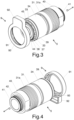
- the connector 3 is inserted in the direction D from the coupling side 2a into the seat 2b of the main body 2 of the multi-connector device 1 and screwed into the seat 2b in the direction of the arrow in the figure.
- at least one seat 2b of the main body 2 is provided with a thread 2c, as in the present embodiment, or with an element with a thread, which thread is open towards the coupling side 2a and is complementary to the thread 31a of the tubular body 31 of the connector 3.
- the disconnection means 9 can then be operated to release the complementary connector 80.
- the connectors of this multi-connector device can be without an annular groove, since the fixing between the two multi-connector devices 1, 11 is made for example by means of the cams 5 and the followers 14 or other fastening mechanisms, whereby the disconnection means 9 of the connectors 3 remain in their seats 2d of the main body 2 of the multi-connector device 1 .
Landscapes
- Engineering & Computer Science (AREA)
- General Engineering & Computer Science (AREA)
- Mechanical Engineering (AREA)
- Quick-Acting Or Multi-Walled Pipe Joints (AREA)
- Fluid-Pressure Circuits (AREA)
- Connector Housings Or Holding Contact Members (AREA)
Claims (11)
- Verbinder (3), umfassend mindestens einen rohrförmigen Körper (31), der mit mindestens einer Mündung (38) versehen ist, die geeignet ist, mit einem komplementären Verbinder (13, 80) gekoppelt zu werden, wobei der rohrförmige Körper (31) auch mit einer Reihe von radialen Öffnungen (32) versehen ist, die teilweise eine Vielzahl von Kugeln (33) aufnehmen, die entlang eines Umfangs des rohrförmigen Körpers (31) angeordnet sind, wobei die Kugeln (33) mit Verbindungsmitteln (34, 35) zusammenwirken, um sich in einer radialen Richtung des rohrförmigen Körpers (31) zwischen einer ausgefahrenen Position, in der sie in Richtung der Außenseite des rohrförmigen Körpers (31) hervorstehen, und einer eingezogenen Position, in der sie in Richtung der Innenseite des rohrförmigen Körpers (31) hervorstehen, zu bewegen, wobei ein Gewinde (31a) um den rohrförmigen Körper (31) oder um ein mit dem rohrförmigen Körper (31) integriertes Element herum gebildet ist, wobei das Gewinde (31a) von der der Mündung (38) des Verbinders (3) gegenüberliegenden Seite offen ist, so dass der Verbinder (3) in einen entsprechenden Gewindesitz in einer Richtung (D), die der der Mündung (38) gegenüberliegenden Seite zugewandt ist, eingeschraubt werden kann, wobei die Verbindungsmittel (34, 35) mindestens einen Ring (34) umfassen, der um den rohrförmigen Körper (31) herum angeordnet ist, um mit den Kugeln (33) zusammenzuwirken und durch mindestens eine Feder (35), die zwischen dem Ring (34) und dem rohrförmigen Körper (31) wirkt, axial vorgespannt zu werden, dadurch gekennzeichnet, dass Trennmittel (9) axial an dem Ring (34) befestigt sind und sich in Bezug auf den Ring (34) um dessen Längsachse herum drehen können.
- Verbinder (3) nach dem vorhergehenden Anspruch, wobei die Trennmittel (9) einen Drücker umfassen, der mit einem ringförmigen Körper (91) versehen ist, der mit einem radialen Vorsprung (92) verbunden ist, wobei der ringförmige Körper (91) mit dem Ring (34) drehbar um den Ring (34) herum verbunden ist.
- Verbinder (3) nach dem vorhergehenden Anspruch, wobei der ringförmige Körper (91) mit mindestens einem Vorsprung (93) versehen ist, der in mindestens einer Ringnut (39) des Rings (34) angeordnet ist oder umgekehrt.
- Verbinder (3) nach einem der vorhergehenden Ansprüche, wobei mindestens ein Anschlussstück (40), das mindestens eine Mündung (41) des Anschlussstücks (40) umfasst, mit dem rohrförmigen Körper (31) von der der Mündung (38) des rohrförmigen Körpers (31) gegenüberliegenden Seite her verbunden ist und vollständig in einem idealen Zylinder enthalten ist, der einen Durchmesser (C) aufweist, der gleich dem Außendurchmesser des Gewindes (31a) des rohrförmigen Körpers (31) ist.
- Verbinder (3) nach einem der vorhergehenden Ansprüche, wobei der Verbinder ein Buchsenverbinder mit einer flachen Mündung ist.
- Werkzeug (50), das geeignet ist, einen Verbinder (3) nach einem der vorhergehenden Ansprüche in einer Mehrfachverbindervorrichtung (2) zu montieren und/oder von dieser zu entfernen, wobei dieser Verbinder (3) mindestens einen rohrförmigen Körper (31) umfasst, der mit mindestens einer Mündung (38) versehen ist, die geeignet ist, mit einem komplementären Verbinder (13, 80) gekoppelt zu werden, wobei der rohrförmige Körper (31) auch mit einer Reihe von radialen Öffnungen (32) versehen ist, die teilweise eine Vielzahl von Kugeln (33) aufnehmen, die entlang eines Umfangs des rohrförmigen Körpers (31) angeordnet sind, wobei die Kugeln (33) mit Verbindungsmitteln (34, 35) zusammenwirken, um sich in einer radialen Richtung des rohrförmigen Körpers (31) zwischen einer ausgefahrenen Position, in der sie in Richtung der Außenseite des rohrförmigen Körpers (31) hervorstehen, und einer eingezogenen Position, in der sie in Richtung der Innenseite des rohrförmigen Körpers (31) hervorstehen, zu bewegen, wobei ein Gewinde (31a) um den rohrförmigen Körper (31) oder um ein mit dem rohrförmigen Körper (31) integriertes Element herum gebildet ist, wobei das Gewinde (31a) von der der Mündung (38) des Verbinders (3) gegenüberliegenden Seite offen ist, so dass der Verbinder (3) in einen entsprechenden Gewindesitz in einer Richtung (D), die der der Mündung (38) gegenüberliegenden Seite zugewandt ist, eingeschraubt werden kann, wobei das Werkzeug (50) einen Kopf (51) umfasst, der geeignet ist, mechanisch mit einem Utensil gekoppelt zu werden, um ein Drehmoment auf das Werkzeug (50) zu übertragen, und der mechanisch mit einem Schaft (53) verbunden ist, wobei eine Vielzahl von radialen Sitzen (54) an der Außenseite des Schafts (53) erhalten werden und entlang eines Umfangs angeordnet sind, um die Vielzahl von Kugeln (33) des Verbinders (3) teilweise aufzunehmen, um das Werkzeug (50) mit dem Verbinder (3) zu koppeln, um das Drehmoment auf den Verbinder (3) zu übertragen.
- Werkzeug (50) nach dem vorhergehenden Anspruch, wobei der Kopf (51) mittels einer Manschette (52), die radial in Bezug auf den Schaft (53) hervorsteht, mechanisch mit dem Schaft (53) verbunden ist.
- Werkzeug (50) nach Anspruch 6 oder 7, wobei mindestens der Schaft (53) einen axialen Hohlraum (55) aufweist.
- Mehrfachverbindervorrichtung (1), umfassend mindestens einen Verbinder (3) nach einem der Ansprüche 1 bis 5, wobei die Mehrfachverbindervorrichtung (1) ferner mindestens einen Hauptkörper (2) umfasst, der mit mindestens einer Kopplungsseite (2a) und einem oder mehreren Sitzen (2b) versehen ist, die geeignet sind, den mindestens einen Verbinder (3) zumindest teilweise aufzunehmen, wobei mindestens ein Sitz (2b) des Hauptkörpers (2) mit einem Gewinde (2c) oder einem Element mit einem Gewinde versehen ist, wobei das Gewinde in Richtung der Kopplungsseite (2a) offen ist, so dass der Verbinder (3) von der Kopplungsseite (2a) in den Sitz (2b) des Hauptkörpers (2) eingeführt und in diesen Sitz (2b) eingeschraubt werden kann.
- Mehrfachverbindervorrichtung (1) nach dem vorhergehenden Anspruch, wobei die Mündung (2e) eines Kanals in dem Sitz (2b) für den Verbinder (3) auf der der Kopplungsseite (2a) gegenüberliegenden Seite angeordnet ist, um eine Hydraulikleitung mit dem in diesem Sitz (2b) angeordneten Verbinder (3) herzustellen.
- Mehrfachverbindervorrichtung (1) nach Anspruch 9 oder 10, wobei mindestens ein Sitz (2d) für die Trennmittel (9) des Verbinders (3) in der Kopplungsseite (2a) des Hauptkörpers (2) um den Sitz (2b) für den Verbinder (3) herum gebildet ist.
Applications Claiming Priority (2)
| Application Number | Priority Date | Filing Date | Title |
|---|---|---|---|
| IT102021000011777A IT202100011777A1 (it) | 2021-05-07 | 2021-05-07 | Innesto per linee idrauliche, dispositivo multi-innesto per questo innesto ed attrezzo per montare e/o smontare l’innesto |
| PCT/IB2022/054197 WO2022234529A1 (en) | 2021-05-07 | 2022-05-06 | Connector for hydraulic lines, multi-connector device for this connector and tool for mounting and/or dismounting the connector |
Publications (2)
| Publication Number | Publication Date |
|---|---|
| EP4334625A1 EP4334625A1 (de) | 2024-03-13 |
| EP4334625B1 true EP4334625B1 (de) | 2025-01-29 |
Family
ID=77412025
Family Applications (1)
| Application Number | Title | Priority Date | Filing Date |
|---|---|---|---|
| EP22726298.7A Active EP4334625B1 (de) | 2021-05-07 | 2022-05-06 | Verbinder für hydraulikleitungen, mehrfachverbindervorrichtung für diesen verbinder und werkzeug zur montage und/oder demontage des verbinders |
Country Status (5)
| Country | Link |
|---|---|
| US (1) | US12455033B2 (de) |
| EP (1) | EP4334625B1 (de) |
| CN (1) | CN117425794A (de) |
| IT (1) | IT202100011777A1 (de) |
| WO (1) | WO2022234529A1 (de) |
Family Cites Families (11)
| Publication number | Priority date | Publication date | Assignee | Title |
|---|---|---|---|---|
| US2399515A (en) * | 1943-10-01 | 1946-04-30 | Thompson Prod Inc | Multiple quick disconnect coupling |
| US5996452A (en) * | 1998-10-13 | 1999-12-07 | Chiang; Shu Chi | Chuck device for power tool |
| US6324962B1 (en) * | 2000-04-10 | 2001-12-04 | Crary Company | Valve block mounting arrangement |
| DE10230293A1 (de) * | 2002-07-05 | 2004-06-03 | Dart Engineering Ag | Flat-Face-Kupplung |
| JP2005121198A (ja) * | 2003-10-20 | 2005-05-12 | Honda Motor Co Ltd | 菅継ぎ装置 |
| ITMI20120429A1 (it) * | 2012-03-19 | 2013-09-20 | Faster Spa | Dispositivo multiconnessione |
| EP2884146B8 (de) | 2013-12-10 | 2017-04-19 | Faster S.p.A. | Mehrfachverbindervorrichtung für die Mehrfachschnellverbindung von mehreren hydraulischen, elektrischen und/oder pneumatischen Leitungen mit der Möglichkeit einzelner manueller Verbinder |
| US20170307123A1 (en) * | 2016-04-20 | 2017-10-26 | Hsiu-Hsiung LIU | Connector assembly |
| US10247341B2 (en) * | 2017-08-07 | 2019-04-02 | Hsiu-Hsiung LIU | Quick connect fitting |
| EP3714197B1 (de) * | 2017-11-20 | 2022-01-05 | Parker-Hannifin Corporation | Verriegelungsvorrichtung für mehrfachkopplung |
| US12222058B2 (en) * | 2021-01-04 | 2025-02-11 | Oetiker Ny, Inc. | Tamper resistant fluid connection assembly with visual connection verifier |
-
2021
- 2021-05-07 IT IT102021000011777A patent/IT202100011777A1/it unknown
-
2022
- 2022-05-06 US US18/289,648 patent/US12455033B2/en active Active
- 2022-05-06 CN CN202280033069.7A patent/CN117425794A/zh active Pending
- 2022-05-06 WO PCT/IB2022/054197 patent/WO2022234529A1/en not_active Ceased
- 2022-05-06 EP EP22726298.7A patent/EP4334625B1/de active Active
Also Published As
| Publication number | Publication date |
|---|---|
| WO2022234529A1 (en) | 2022-11-10 |
| IT202100011777A1 (it) | 2022-11-07 |
| US12455033B2 (en) | 2025-10-28 |
| US20240255086A1 (en) | 2024-08-01 |
| CN117425794A (zh) | 2024-01-19 |
| EP4334625A1 (de) | 2024-03-13 |
Similar Documents
| Publication | Publication Date | Title |
|---|---|---|
| EP3440747B1 (de) | Verbindungssystem mit adaptiertem bajonettverschlussvorrichtung zum schnellen lösen | |
| EP1666783B1 (de) | Rohrverbindung und muffe für rohrverbindung | |
| KR102388166B1 (ko) | 다수-라인 연결 신속 다중-커플링 | |
| CA2671232C (en) | Locking pin | |
| US5340248A (en) | Mechanical chuck with clamp for pulling tool shank to tightly clamped position | |
| CN110230645B (zh) | 一种快速连接装置 | |
| EP3714197B1 (de) | Verriegelungsvorrichtung für mehrfachkopplung | |
| US20220324034A1 (en) | Operating key for stationary and driven tool holders | |
| US4974635A (en) | Coupler with spring-locked valves | |
| US20100200240A1 (en) | Multicoupler | |
| CN209487859U (zh) | 一种快速插拔多芯连接器 | |
| US12455033B2 (en) | Connector for hydraulic lines, multi-connector device for this connector and tool for mounting and/or dismounting the connector | |
| EP2424048B1 (de) | Verbindungsstecker und Verbindungseinrichtung zum Herstellen einer lösbaren Verbindung | |
| CN115030946B (zh) | 插销式快卸膨胀装置 | |
| JP2009289644A (ja) | コネクタ | |
| KR100332307B1 (ko) | 콘넥터 | |
| CN221041716U (zh) | 一种扁平安装快锁连接器 | |
| CN219311773U (zh) | 手套生产用手模组件安装结构 | |
| CN214380500U (zh) | 电机快换结构 | |
| CN216952148U (zh) | 一种快速接头锁扣结构及其快速接头 | |
| CN213906485U (zh) | 直连安装的电机快换结构 | |
| CN213906540U (zh) | 直连安装的电机快换结构 | |
| CN112510963B (zh) | 直连安装的电机快换结构 | |
| US6276880B1 (en) | Tool interconnect structure | |
| CN112542917A (zh) | 直连安装的电机快换结构 |
Legal Events
| Date | Code | Title | Description |
|---|---|---|---|
| STAA | Information on the status of an ep patent application or granted ep patent |
Free format text: STATUS: UNKNOWN |
|
| STAA | Information on the status of an ep patent application or granted ep patent |
Free format text: STATUS: THE INTERNATIONAL PUBLICATION HAS BEEN MADE |
|
| PUAI | Public reference made under article 153(3) epc to a published international application that has entered the european phase |
Free format text: ORIGINAL CODE: 0009012 |
|
| STAA | Information on the status of an ep patent application or granted ep patent |
Free format text: STATUS: REQUEST FOR EXAMINATION WAS MADE |
|
| 17P | Request for examination filed |
Effective date: 20231127 |
|
| AK | Designated contracting states |
Kind code of ref document: A1 Designated state(s): AL AT BE BG CH CY CZ DE DK EE ES FI FR GB GR HR HU IE IS IT LI LT LU LV MC MK MT NL NO PL PT RO RS SE SI SK SM TR |
|
| P01 | Opt-out of the competence of the unified patent court (upc) registered |
Effective date: 20240315 |
|
| DAV | Request for validation of the european patent (deleted) | ||
| DAX | Request for extension of the european patent (deleted) | ||
| GRAP | Despatch of communication of intention to grant a patent |
Free format text: ORIGINAL CODE: EPIDOSNIGR1 |
|
| STAA | Information on the status of an ep patent application or granted ep patent |
Free format text: STATUS: GRANT OF PATENT IS INTENDED |
|
| INTG | Intention to grant announced |
Effective date: 20240913 |
|
| GRAS | Grant fee paid |
Free format text: ORIGINAL CODE: EPIDOSNIGR3 |
|
| GRAA | (expected) grant |
Free format text: ORIGINAL CODE: 0009210 |
|
| STAA | Information on the status of an ep patent application or granted ep patent |
Free format text: STATUS: THE PATENT HAS BEEN GRANTED |
|
| AK | Designated contracting states |
Kind code of ref document: B1 Designated state(s): AL AT BE BG CH CY CZ DE DK EE ES FI FR GB GR HR HU IE IS IT LI LT LU LV MC MK MT NL NO PL PT RO RS SE SI SK SM TR |
|
| REG | Reference to a national code |
Ref country code: GB Ref legal event code: FG4D |
|
| REG | Reference to a national code |
Ref country code: CH Ref legal event code: EP |
|
| REG | Reference to a national code |
Ref country code: DE Ref legal event code: R096 Ref document number: 602022010215 Country of ref document: DE |
|
| REG | Reference to a national code |
Ref country code: IE Ref legal event code: FG4D |
|
| REG | Reference to a national code |
Ref country code: NL Ref legal event code: MP Effective date: 20250129 |
|
| PG25 | Lapsed in a contracting state [announced via postgrant information from national office to epo] |
Ref country code: NL Free format text: LAPSE BECAUSE OF FAILURE TO SUBMIT A TRANSLATION OF THE DESCRIPTION OR TO PAY THE FEE WITHIN THE PRESCRIBED TIME-LIMIT Effective date: 20250129 |
|
| PG25 | Lapsed in a contracting state [announced via postgrant information from national office to epo] |
Ref country code: RS Free format text: LAPSE BECAUSE OF FAILURE TO SUBMIT A TRANSLATION OF THE DESCRIPTION OR TO PAY THE FEE WITHIN THE PRESCRIBED TIME-LIMIT Effective date: 20250429 |
|
| PG25 | Lapsed in a contracting state [announced via postgrant information from national office to epo] |
Ref country code: FI Free format text: LAPSE BECAUSE OF FAILURE TO SUBMIT A TRANSLATION OF THE DESCRIPTION OR TO PAY THE FEE WITHIN THE PRESCRIBED TIME-LIMIT Effective date: 20250129 |
|
| PG25 | Lapsed in a contracting state [announced via postgrant information from national office to epo] |
Ref country code: PL Free format text: LAPSE BECAUSE OF FAILURE TO SUBMIT A TRANSLATION OF THE DESCRIPTION OR TO PAY THE FEE WITHIN THE PRESCRIBED TIME-LIMIT Effective date: 20250129 |
|
| PGFP | Annual fee paid to national office [announced via postgrant information from national office to epo] |
Ref country code: DE Payment date: 20250528 Year of fee payment: 4 |
|
| PG25 | Lapsed in a contracting state [announced via postgrant information from national office to epo] |
Ref country code: ES Free format text: LAPSE BECAUSE OF FAILURE TO SUBMIT A TRANSLATION OF THE DESCRIPTION OR TO PAY THE FEE WITHIN THE PRESCRIBED TIME-LIMIT Effective date: 20250129 |
|
| REG | Reference to a national code |
Ref country code: LT Ref legal event code: MG9D |
|
| PG25 | Lapsed in a contracting state [announced via postgrant information from national office to epo] |
Ref country code: IS Free format text: LAPSE BECAUSE OF FAILURE TO SUBMIT A TRANSLATION OF THE DESCRIPTION OR TO PAY THE FEE WITHIN THE PRESCRIBED TIME-LIMIT Effective date: 20250529 Ref country code: NO Free format text: LAPSE BECAUSE OF FAILURE TO SUBMIT A TRANSLATION OF THE DESCRIPTION OR TO PAY THE FEE WITHIN THE PRESCRIBED TIME-LIMIT Effective date: 20250429 |
|
| PGFP | Annual fee paid to national office [announced via postgrant information from national office to epo] |
Ref country code: IT Payment date: 20250531 Year of fee payment: 4 |
|
| REG | Reference to a national code |
Ref country code: AT Ref legal event code: MK05 Ref document number: 1763748 Country of ref document: AT Kind code of ref document: T Effective date: 20250129 |
|
| PG25 | Lapsed in a contracting state [announced via postgrant information from national office to epo] |
Ref country code: HR Free format text: LAPSE BECAUSE OF FAILURE TO SUBMIT A TRANSLATION OF THE DESCRIPTION OR TO PAY THE FEE WITHIN THE PRESCRIBED TIME-LIMIT Effective date: 20250129 |
|
| PG25 | Lapsed in a contracting state [announced via postgrant information from national office to epo] |
Ref country code: LV Free format text: LAPSE BECAUSE OF FAILURE TO SUBMIT A TRANSLATION OF THE DESCRIPTION OR TO PAY THE FEE WITHIN THE PRESCRIBED TIME-LIMIT Effective date: 20250129 Ref country code: PT Free format text: LAPSE BECAUSE OF FAILURE TO SUBMIT A TRANSLATION OF THE DESCRIPTION OR TO PAY THE FEE WITHIN THE PRESCRIBED TIME-LIMIT Effective date: 20250529 |
|
| PGFP | Annual fee paid to national office [announced via postgrant information from national office to epo] |
Ref country code: FR Payment date: 20250516 Year of fee payment: 4 |
|
| PG25 | Lapsed in a contracting state [announced via postgrant information from national office to epo] |
Ref country code: BG Free format text: LAPSE BECAUSE OF FAILURE TO SUBMIT A TRANSLATION OF THE DESCRIPTION OR TO PAY THE FEE WITHIN THE PRESCRIBED TIME-LIMIT Effective date: 20250129 Ref country code: GR Free format text: LAPSE BECAUSE OF FAILURE TO SUBMIT A TRANSLATION OF THE DESCRIPTION OR TO PAY THE FEE WITHIN THE PRESCRIBED TIME-LIMIT Effective date: 20250430 |
|
| PG25 | Lapsed in a contracting state [announced via postgrant information from national office to epo] |
Ref country code: AT Free format text: LAPSE BECAUSE OF FAILURE TO SUBMIT A TRANSLATION OF THE DESCRIPTION OR TO PAY THE FEE WITHIN THE PRESCRIBED TIME-LIMIT Effective date: 20250129 |
|
| PG25 | Lapsed in a contracting state [announced via postgrant information from national office to epo] |
Ref country code: SE Free format text: LAPSE BECAUSE OF FAILURE TO SUBMIT A TRANSLATION OF THE DESCRIPTION OR TO PAY THE FEE WITHIN THE PRESCRIBED TIME-LIMIT Effective date: 20250129 |
|
| PG25 | Lapsed in a contracting state [announced via postgrant information from national office to epo] |
Ref country code: SM Free format text: LAPSE BECAUSE OF FAILURE TO SUBMIT A TRANSLATION OF THE DESCRIPTION OR TO PAY THE FEE WITHIN THE PRESCRIBED TIME-LIMIT Effective date: 20250129 |
|
| PG25 | Lapsed in a contracting state [announced via postgrant information from national office to epo] |
Ref country code: DK Free format text: LAPSE BECAUSE OF FAILURE TO SUBMIT A TRANSLATION OF THE DESCRIPTION OR TO PAY THE FEE WITHIN THE PRESCRIBED TIME-LIMIT Effective date: 20250129 |
|
| PG25 | Lapsed in a contracting state [announced via postgrant information from national office to epo] |
Ref country code: EE Free format text: LAPSE BECAUSE OF FAILURE TO SUBMIT A TRANSLATION OF THE DESCRIPTION OR TO PAY THE FEE WITHIN THE PRESCRIBED TIME-LIMIT Effective date: 20250129 Ref country code: CZ Free format text: LAPSE BECAUSE OF FAILURE TO SUBMIT A TRANSLATION OF THE DESCRIPTION OR TO PAY THE FEE WITHIN THE PRESCRIBED TIME-LIMIT Effective date: 20250129 |
|
| PG25 | Lapsed in a contracting state [announced via postgrant information from national office to epo] |
Ref country code: RO Free format text: LAPSE BECAUSE OF FAILURE TO SUBMIT A TRANSLATION OF THE DESCRIPTION OR TO PAY THE FEE WITHIN THE PRESCRIBED TIME-LIMIT Effective date: 20250129 |
|
| PG25 | Lapsed in a contracting state [announced via postgrant information from national office to epo] |
Ref country code: SK Free format text: LAPSE BECAUSE OF FAILURE TO SUBMIT A TRANSLATION OF THE DESCRIPTION OR TO PAY THE FEE WITHIN THE PRESCRIBED TIME-LIMIT Effective date: 20250129 |
|
| REG | Reference to a national code |
Ref country code: DE Ref legal event code: R097 Ref document number: 602022010215 Country of ref document: DE |
|
| PLBE | No opposition filed within time limit |
Free format text: ORIGINAL CODE: 0009261 |
|
| STAA | Information on the status of an ep patent application or granted ep patent |
Free format text: STATUS: NO OPPOSITION FILED WITHIN TIME LIMIT |
|
| REG | Reference to a national code |
Ref country code: CH Ref legal event code: L10 Free format text: ST27 STATUS EVENT CODE: U-0-0-L10-L00 (AS PROVIDED BY THE NATIONAL OFFICE) Effective date: 20251210 |
|
| REG | Reference to a national code |
Ref country code: CH Ref legal event code: H13 Free format text: ST27 STATUS EVENT CODE: U-0-0-H10-H13 (AS PROVIDED BY THE NATIONAL OFFICE) Effective date: 20251223 |
|
| 26N | No opposition filed |
Effective date: 20251030 |
|
| PG25 | Lapsed in a contracting state [announced via postgrant information from national office to epo] |
Ref country code: LU Free format text: LAPSE BECAUSE OF NON-PAYMENT OF DUE FEES Effective date: 20250506 |
|
| PG25 | Lapsed in a contracting state [announced via postgrant information from national office to epo] |
Ref country code: CH Free format text: LAPSE BECAUSE OF NON-PAYMENT OF DUE FEES Effective date: 20250531 |
|
| REG | Reference to a national code |
Ref country code: BE Ref legal event code: MM Effective date: 20250531 |
|
| PG25 | Lapsed in a contracting state [announced via postgrant information from national office to epo] |
Ref country code: MC Free format text: LAPSE BECAUSE OF FAILURE TO SUBMIT A TRANSLATION OF THE DESCRIPTION OR TO PAY THE FEE WITHIN THE PRESCRIBED TIME-LIMIT Effective date: 20250129 |
|
| PG25 | Lapsed in a contracting state [announced via postgrant information from national office to epo] |
Ref country code: IE Free format text: LAPSE BECAUSE OF NON-PAYMENT OF DUE FEES Effective date: 20250506 |
|
| PG25 | Lapsed in a contracting state [announced via postgrant information from national office to epo] |
Ref country code: BE Free format text: LAPSE BECAUSE OF NON-PAYMENT OF DUE FEES Effective date: 20250531 |