EP4333752B1 - Caiman ring forceps - manuelle hf aktivierung - Google Patents
Caiman ring forceps - manuelle hf aktivierung Download PDFInfo
- Publication number
- EP4333752B1 EP4333752B1 EP23701003.8A EP23701003A EP4333752B1 EP 4333752 B1 EP4333752 B1 EP 4333752B1 EP 23701003 A EP23701003 A EP 23701003A EP 4333752 B1 EP4333752 B1 EP 4333752B1
- Authority
- EP
- European Patent Office
- Prior art keywords
- instrument
- activation
- activation element
- branch
- blade
- Prior art date
- Legal status (The legal status is an assumption and is not a legal conclusion. Google has not performed a legal analysis and makes no representation as to the accuracy of the status listed.)
- Active
Links
Images







Classifications
-
- A—HUMAN NECESSITIES
- A61—MEDICAL OR VETERINARY SCIENCE; HYGIENE
- A61B—DIAGNOSIS; SURGERY; IDENTIFICATION
- A61B18/00—Surgical instruments, devices or methods for transferring non-mechanical forms of energy to or from the body
- A61B18/04—Surgical instruments, devices or methods for transferring non-mechanical forms of energy to or from the body by heating
- A61B18/12—Surgical instruments, devices or methods for transferring non-mechanical forms of energy to or from the body by heating by passing a current through the tissue to be heated, e.g. high-frequency current
- A61B18/14—Probes or electrodes therefor
- A61B18/1442—Probes having pivoting end effectors, e.g. forceps
-
- A—HUMAN NECESSITIES
- A61—MEDICAL OR VETERINARY SCIENCE; HYGIENE
- A61B—DIAGNOSIS; SURGERY; IDENTIFICATION
- A61B18/00—Surgical instruments, devices or methods for transferring non-mechanical forms of energy to or from the body
- A61B18/04—Surgical instruments, devices or methods for transferring non-mechanical forms of energy to or from the body by heating
- A61B18/12—Surgical instruments, devices or methods for transferring non-mechanical forms of energy to or from the body by heating by passing a current through the tissue to be heated, e.g. high-frequency current
- A61B18/1206—Generators therefor
-
- A—HUMAN NECESSITIES
- A61—MEDICAL OR VETERINARY SCIENCE; HYGIENE
- A61B—DIAGNOSIS; SURGERY; IDENTIFICATION
- A61B18/00—Surgical instruments, devices or methods for transferring non-mechanical forms of energy to or from the body
- A61B2018/00053—Mechanical features of the instrument of device
- A61B2018/00184—Moving parts
-
- A—HUMAN NECESSITIES
- A61—MEDICAL OR VETERINARY SCIENCE; HYGIENE
- A61B—DIAGNOSIS; SURGERY; IDENTIFICATION
- A61B18/00—Surgical instruments, devices or methods for transferring non-mechanical forms of energy to or from the body
- A61B2018/00571—Surgical instruments, devices or methods for transferring non-mechanical forms of energy to or from the body for achieving a particular surgical effect
- A61B2018/00601—Cutting
-
- A—HUMAN NECESSITIES
- A61—MEDICAL OR VETERINARY SCIENCE; HYGIENE
- A61B—DIAGNOSIS; SURGERY; IDENTIFICATION
- A61B18/00—Surgical instruments, devices or methods for transferring non-mechanical forms of energy to or from the body
- A61B2018/00571—Surgical instruments, devices or methods for transferring non-mechanical forms of energy to or from the body for achieving a particular surgical effect
- A61B2018/0063—Sealing
-
- A—HUMAN NECESSITIES
- A61—MEDICAL OR VETERINARY SCIENCE; HYGIENE
- A61B—DIAGNOSIS; SURGERY; IDENTIFICATION
- A61B18/00—Surgical instruments, devices or methods for transferring non-mechanical forms of energy to or from the body
- A61B2018/00636—Sensing and controlling the application of energy
- A61B2018/00696—Controlled or regulated parameters
- A61B2018/00702—Power or energy
- A61B2018/00708—Power or energy switching the power on or off
-
- A—HUMAN NECESSITIES
- A61—MEDICAL OR VETERINARY SCIENCE; HYGIENE
- A61B—DIAGNOSIS; SURGERY; IDENTIFICATION
- A61B18/00—Surgical instruments, devices or methods for transferring non-mechanical forms of energy to or from the body
- A61B2018/0091—Handpieces of the surgical instrument or device
- A61B2018/00916—Handpieces of the surgical instrument or device with means for switching or controlling the main function of the instrument or device
-
- A—HUMAN NECESSITIES
- A61—MEDICAL OR VETERINARY SCIENCE; HYGIENE
- A61B—DIAGNOSIS; SURGERY; IDENTIFICATION
- A61B18/00—Surgical instruments, devices or methods for transferring non-mechanical forms of energy to or from the body
- A61B2018/0091—Handpieces of the surgical instrument or device
- A61B2018/00916—Handpieces of the surgical instrument or device with means for switching or controlling the main function of the instrument or device
- A61B2018/00922—Handpieces of the surgical instrument or device with means for switching or controlling the main function of the instrument or device by switching or controlling the treatment energy directly within the hand-piece
-
- A—HUMAN NECESSITIES
- A61—MEDICAL OR VETERINARY SCIENCE; HYGIENE
- A61B—DIAGNOSIS; SURGERY; IDENTIFICATION
- A61B18/00—Surgical instruments, devices or methods for transferring non-mechanical forms of energy to or from the body
- A61B2018/0091—Handpieces of the surgical instrument or device
- A61B2018/00916—Handpieces of the surgical instrument or device with means for switching or controlling the main function of the instrument or device
- A61B2018/0094—Types of switches or controllers
-
- A—HUMAN NECESSITIES
- A61—MEDICAL OR VETERINARY SCIENCE; HYGIENE
- A61B—DIAGNOSIS; SURGERY; IDENTIFICATION
- A61B18/00—Surgical instruments, devices or methods for transferring non-mechanical forms of energy to or from the body
- A61B2018/0091—Handpieces of the surgical instrument or device
- A61B2018/00916—Handpieces of the surgical instrument or device with means for switching or controlling the main function of the instrument or device
- A61B2018/0094—Types of switches or controllers
- A61B2018/00946—Types of switches or controllers slidable
-
- A—HUMAN NECESSITIES
- A61—MEDICAL OR VETERINARY SCIENCE; HYGIENE
- A61B—DIAGNOSIS; SURGERY; IDENTIFICATION
- A61B18/00—Surgical instruments, devices or methods for transferring non-mechanical forms of energy to or from the body
- A61B18/04—Surgical instruments, devices or methods for transferring non-mechanical forms of energy to or from the body by heating
- A61B18/12—Surgical instruments, devices or methods for transferring non-mechanical forms of energy to or from the body by heating by passing a current through the tissue to be heated, e.g. high-frequency current
- A61B18/1206—Generators therefor
- A61B2018/1246—Generators therefor characterised by the output polarity
- A61B2018/126—Generators therefor characterised by the output polarity bipolar
-
- A—HUMAN NECESSITIES
- A61—MEDICAL OR VETERINARY SCIENCE; HYGIENE
- A61B—DIAGNOSIS; SURGERY; IDENTIFICATION
- A61B18/00—Surgical instruments, devices or methods for transferring non-mechanical forms of energy to or from the body
- A61B18/04—Surgical instruments, devices or methods for transferring non-mechanical forms of energy to or from the body by heating
- A61B18/12—Surgical instruments, devices or methods for transferring non-mechanical forms of energy to or from the body by heating by passing a current through the tissue to be heated, e.g. high-frequency current
- A61B18/14—Probes or electrodes therefor
- A61B18/1442—Probes having pivoting end effectors, e.g. forceps
- A61B2018/1452—Probes having pivoting end effectors, e.g. forceps including means for cutting
- A61B2018/1455—Probes having pivoting end effectors, e.g. forceps including means for cutting having a moving blade for cutting tissue grasped by the jaws
Definitions
- the present disclosure relates to a (medical) bipolar HF instrument, preferably of the scissors or forceps type, with a first and a second (crossing in a hinge) instrument branches, which form or have a jaw part, for example for grasping tissue, on a distal instrument end section and holding/actuating geometries (handles, finger rings, etc.) on a proximal instrument end section, all of which are intended and designed to move away from one another when opening and towards one another when closing for manual cutting and (HF) sealing of tissue, in particular in open surgery.
- a (medical) bipolar HF instrument preferably of the scissors or forceps type
- a first and a second (crossing in a hinge) instrument branches which form or have a jaw part, for example for grasping tissue, on a distal instrument end section and holding/actuating geometries (handles, finger rings, etc.) on a proximal instrument end section, all of which are intended and designed to move away from one another when opening and towards one
- surgical sealing and cutting instruments of the above type which use a high-frequency (HF) current for sealing using bipolar technology and a mechanical blade for cutting (biological) tissue.
- HF high-frequency
- Automatic permanent activation is provided when the branches are pressed together.
- a blade lock is often integrated into the instrument as a safety precaution when the branches are open.
- An HF button that is also provided usually provides tactile feedback in two stages (2-click button). A first click gives a user an indication that a defined closing state has been reached and a second click activates the HF current.
- This state-of-the-art surgical instrument enables fast operation, especially for experienced users.
- the surgical instrument has clearly separated functions for cutting and sealing and low manufacturing costs.
- a surgical instrument that uses ultrasound for sealing and cutting, whereby the sealing and cutting can be manually activated at any time.
- This surgical instrument also offers the choice between a MIN or MAX mode on the instrument. It is an advantage that no unwanted activation is possible when closing, especially since the user has free choice and this provides more control and safety.
- the known surgical instruments have the disadvantage that the HF button must be held permanently, which can be ergonomically unfriendly and tiring for the user in the long term, especially since multiple activations per operation are conceivable.
- Another disadvantage can be the variation in the pressure applied. The user can vary the actuation pressure on the instrument/its branches using the force of their hand, and thus potentially have a negative impact on the sealing result.
- Accidental HF activation when squeezing too quickly and a preferred orientation during handling due to the asymmetrical arrangement of the blade actuation element are further disadvantages.
- the US 10 188 450 B2 describes a forceps having first and second shafts (branch), each having a jaw member disposed at a distal end thereof. At least one jaw member is movable from an open to a closed position to grasp tissue therebetween. At least one jaw member is configured to reciprocate a blade.
- a trigger assembly includes a trigger and at least one linkage connected to the trigger and the blade such that rotation of the trigger translates the blade between the retracted and extended positions.
- An engaging member movable between a locked position and an unlocked position is also provided. The engaging member is configured to engage the linkage(s) in the locked position. to prevent the blade from moving from the retracted to the extended position.
- the US 10 660 694 B2 describes a switch assembly for an electrosurgical instrument having a switch housing, a switch, a first biasing member, and an additional biasing member.
- the switch is disposed within the switch housing and is movable between an activated position for initiating delivery of electrosurgical energy and a deactivated position for terminating delivery of electrosurgical energy.
- the first biasing member is selectively positionable adjacent to and in communication with the switch.
- the first biasing member includes a first thickness that provides a first resistance to resist movement of the switch between the activated and deactivated positions when positioned within the switch housing.
- the additional biasing member is selectively interchangeable with the first biasing member.
- the additional biasing member has a different thickness that provides a different resistance to resist movement of the switch between the activated and deactivated positions when positioned within the switch housing.
- a bipolar electrosurgical instrument having first and second shafts (branches), each having a jaw member extending from its distal end. Each jaw member is adapted to connect to a source of electrosurgical energy such that the jaw members are capable of selectively conducting energy through the tissue held therebetween.
- a knife channel is configured to reciprocate a cutting mechanism therein.
- An actuator selectively advances the cutting mechanism.
- a switch is disposed on the first shaft and configured to be depressed between a first position and at least one subsequent position in biasing engagement with a mechanical interface disposed on the second shaft. The first position of the switch relays information to the user corresponding to a desired pressure on the tissue and the at least one subsequent position is configured to activate the source of electrosurgical energy to deliver electrosurgical energy to the jaw members.
- the present disclosure is based on the object of providing a bipolar HF instrument which enables simplified operation, in particular over a longer period of time, and furthermore the orientation of the instrument for use is irrelevant. Furthermore, it is a particular aim of the present disclosure to eliminate or at least improve the above disadvantages of the prior art.
- the bipolar HF (hand-held) instrument has a jaw part (for grasping! holding! gripping tissue), as well as a first instrument branch and a second instrument branch (for manually actuating the jaw part), which (all) are intended and designed to move away from one another when opening and towards one another when closing.
- a blade actuating element/blade actuating lever or (sliding) button is provided for activating a mechanical blade mounted in the jaw part for cutting tissue, wherein the mechanical blade is intended and designed to be movable by means of the blade actuating element from a first position (parking/non-cutting position) to a second position (cutting position).
- an HF activation element or activation button/knob/switch is provided for activating/unlocking an HF power supply, in particular for sealing (Coagulation) of tissue and, if necessary, a locking device, preferably designed separately for this purpose, which acts on the branches, is provided in order to (optionally) achieve a locked branch state with the instrument branches closed.
- the HF activation element and preferably the blade actuation element are provided and designed in such a way that they can be operated from two, preferably opposite (or facing away from each other) sides of the HF instrument in a further preferably identical or similar manner.
- This has the advantage that the mechanical blade can always be operated in the same way, regardless of which way or in which hand the instrument is held. Accordingly, there is no preferred orientation or position of the instrument. This also applies to handling by right- or left-handed people. In other words, it is irrelevant how a user holds the bipolar HF instrument, since the operation always works in the same way due to the two-sided design of the blade actuation element and the HF activation element.
- the present object according to the disclosure is a surgical (hand-held) instrument of the scissors or forceps type with bipolar HF technology and a mechanical (tissue cutting) blade.
- the jaw part By opening and closing the instrument branches, the jaw part is also opened and closed.
- tissue can be grasped and sealed using HF (high-frequency energy supply) via electrodes arranged in the jaw part.
- the jaw part can also be used to prepare and manipulate the tissue.
- the tissue In the closed state of the jaw part, the tissue can also be cut using the blade stored in the jaw part.
- the actuating devices for separate and individual manual actuation of the HF power supply and the blade are designed and arranged in such a way that essentially the same actuation geometry results on two opposite or opposite sides of the instrument with essentially the same function/effect on the HF power supply and the blade.
- the mirroring of the The actuation geometry does not necessarily have to be two-dimensional, but can also be three-dimensional.
- both actuation devices for actuating the HF current and blade can be arranged essentially the same (mirror-image) to the left and right of the instrument (two-dimensional duplication) or only one actuation device (blade actuation if applicable) can be arranged to the left and right of the instrument and the other actuation device (HF current supply if applicable) can be arranged above and below the instrument (each in mirror image) (three-dimensional duplication).
- the mechanical blade can be moved from a first position to a second position using the blade actuating element.
- the blade actuating element is moved linearly from its distal resting position to the proximal side.
- the mechanical blade moves linearly from its proximal resting position to the distal side and can thus cut tissue grasped in the jaw part.
- the instrument preferably has a permanently installed locking device in the form of a passage lock.
- the locking device can be used to lock the instrument branches in a defined state (relative position). To lock, the instrument branches are closed until the locked state is reached. To unlock, the branches are pressed together again slightly until the locking device releases.
- the design of the locking device/lock/passage lock is well known from the state of the art and therefore does not need to be described further. It has the significant advantage that it can be used to create a defined closed state in which fluctuations in the closing force are only to be expected to a small extent. This in turn has the advantage that the sealing quality is increased and consistent performance is ensured.
- the locking device enables the user to hold tissue securely without triggering HF activation. Another advantage is that the user can relax his hand when the locking device is closed. It is not necessary to constantly squeeze the instrument. This makes this revelation particularly ergonomic.
- the locking device consists of a male part and a female part.
- HF can be activated and cut when it is closed and locked.
- HF is activated first and a sealing is carried out.
- Tip activation is preferably provided so that the user only has to press the button once and does not have to hold it down permanently.
- An HF generator takes over the logic with its integrated algorithm and switches itself off after a successful sealing.
- the user always has the option of stopping the sealing process by tapping the HF activation button again.
- Cutting can take place in a second step.
- the blade actuating element is pulled proximally. Both the HF activation element and the blade actuating element are automatically reset, preferably by springs.
- sealing and/or cutting functions can be used independently of each other.
- the user has the freedom to use the sealing and/or cutting functions independently of each other.
- a first rack and pinion gear system is provided and arranged in the first instrument branch, in which an input rack is connected to the blade actuating element and an output rack is connected to the mechanical blade, wherein the blade actuating element can be moved linearly from a distal rest position to the proximal position.
- the deflection mechanism required for this in the first instrument branch is a rack and pinion gear system in which the input rack is attached to the blade actuating element and the output rack is attached to the mechanical blade.
- the input rack and the associated blade actuating element are arranged approximately on the plane of symmetry between the first instrument branch and the second instrument branch.
- the rack and pinion mechanism is a significant advantage for the symmetrical use of the instrument.
- the arrangement of the input rod and the associated blade actuation element almost on the plane of symmetry between the first and second instrument branches has the great advantage that the blade can always be actuated in the same way, no matter which way the instrument is held. There is no preferred orientation or position of the instrument in this respect. This also applies to handling by right- or left-handed people.
- the bipolar HF instrument also has a blade lock which is configured in such a way that in an open state the actuation of the mechanical blade is blocked and in a defined closed state the mechanical blade is movable.
- a blade lock which is configured in such a way that in an open state the actuation of the mechanical blade is blocked and in a defined closed state the mechanical blade is movable.
- the blade can be activated as soon as the jaws are sufficiently closed, for example when they touch each other.
- HF activation/activation is always possible. This means that there is no locking of the HF activation element.
- HF can be activated when the instrument is not locked. This gives the user more application options, but also carries the risk of HF activation with insufficient closing force.
- the fixed locking device enables a defined closing state.
- both the blade actuation and the HF actuation are only possible when the instrument is in the locked position of the permanently installed locking device. This ensures that both a cut and an HF sealing are only possible in a clearly defined closed state and guarantees maximum safety.
- this option limits the user's options. Particularly experienced users could perceive this safety concept as a strong limitation. It is therefore preferable if the first security concept is used for experienced users and the second security concept is used for less experienced users.
- the RF activation element is designed and provided in such a way that it can be moved or pivoted or displaced proximally when a seal is carried out.
- the HF activation element is designed and provided in such a way to activate the HF power supply after a first tap activation and to switch it off automatically, preferably by means of an integrated algorithm, after successful sealing or to manually stop the HF power supply after a second tap activation of the HF activation element before successful sealing.
- the HF activation element has an inner part which is mounted in a rocking, sliding or pivoting manner on a rotation axis of the HF activation element in the second instrument branch orthogonal to the proximal-distal direction, wherein the side of the inner part pointing in the direction proximal to the instrument has a contacting element with an activation surface which contacts a first HF activation button when the HF activation element is actuated and activates the HF power supply.
- the design and positioning of the RF actuation button also aims to enable fully symmetrical operation of the instrument, or to avoid the need for a preferred orientation of the instrument.
- the HF activation element is mounted in the second branch so that it can rock around an axis and can be reached equally well from both sides of the instrument. Furthermore, positioning the HF activation element in only one instrument branch has the advantage that the cabling of the HF activation is also only located in one instrument branch. This reduces the effort and costs compared to a concept with actuation buttons/RF activation buttons in both instrument industries.
- the inner part of the RF activation element has a first wing and a second wing, wherein the first wing protrudes laterally on the second instrument branch and the second wing protrudes opposite the first wing on the other side of the second instrument branch.
- the HF activation element consists of several parts, an inner part and a first and a second wing.
- a one-piece design is also conceivable under different installation conditions.
- the HF activation element is a slider that can be moved linearly in the proximal and distal directions.
- the HF activation element is movably guided in, for example, a slot in a housing of the second instrument branch. This has the advantage that exactly one electronic HF activation button is required.
- the activation surface of the RF activation element according to the above embodiment is intended to press the first (electronic) RF activation button.
- the contacting element is provided and designed in a cam-shaped manner in the direction towards the first RF activation button.
- a second rack and pinion gear is placed distally to the first RF activation button in such a way as to contact the activation surface when the RF activation element is actuated.
- the inner part of the HF activation element has a type of cam or similar, which Rotation/pivoting around the axis of rotation of the HF activation element engages the first HF activation button.
- An additional return spring is provided and may be necessary.
- An alternative embodiment not part of the invention when using (exactly) a first HF activation button is provided with a rack and pinion gear.
- the inner part of the HF activation element is also rotatably mounted and connected to a gear.
- Two racks are placed on two sides of the gear, each of which can transfer its movement to a contact element/activation element/pressure plate.
- the contact element then actuates the first HF activation button.
- the contact element is superfluous and the racks can press directly on the HF activation button.
- a second HF activation button is provided and arranged next to the first HF activation button parallel to the inner part of the HF activation element.
- the activation surface of the contacting element exerts a force on one of the two HF activation buttons by twisting/pivoting/moving the HF activation element, thereby triggering an activation of the HF process.
- twisting/pivoting/moving the HF activation element again the HF process can also be stopped manually if necessary.
- the above embodiment has the advantage that the HF activation element can be actuated by both pulling and pressing. This opens up several ergonomic operating options for the user.
- a return to a non-actuated rest position is provided via an integrated spring in the HF activation buttons.
- an additional return spring in the form of a sheet metal/leaf spring, a torsion spring or similar can be provided.
- the inner part of the HF activation element is supported by a spring element, for example a compression spring.
- a spring element causes the entire HF activation element to protrude somewhat in the axial direction of its axis of rotation.
- the activation surface that would press on the first and/or second HF activation button is disengaged and no HF energy supply can be activated when the HF activation element is actuated in this position.
- the HF activation element In a closed state, the HF activation element is pressed in the second instrument branch. In this position, the activation surface is brought back into engagement with the first and/or second HF activation button by closing the first and second instrument branches and the resulting compression of the compression spring in the second instrument branch.
- the HF activation element has a separate return spring that permanently pushes it into a rest position in which the wings of the HF activation element are perpendicular to the main plane of the instrument.
- a leaf spring, tension spring, torsion spring, or similar can be used as a return spring.
- first HF activation button and/or the second HF activation button is/are arranged in the proximal direction away from the inner part of the HF activation element but facing it on a circuit board in the second instrument branch.
- first HF activation button and/or second HF activation button are located on a circuit board on which they are interconnected in an OR logic. This ensures that no matter which of the HF activation buttons is pressed, an action takes place.
- the HF activation element is designed as a lever.
- the position of such a lever is switchable as soon as the bipolar HF instrument is rotated, so that a fully symmetrical actuation of the instrument is also possible. Therefore, the lever is located on both sides of the instrument or the second instrument branch.
- a first and a second HF activation button are provided in the instrument branch or in the housing of the instrument branch, which are positioned opposite each other in such a way that when the lever is in a first position, the first HF activation button is pressed when actuated, and when the lever is in position 2, the second HF activation button is pressed when actuated. Switching from position 1 to position 2 is preferably achieved by a snap mechanism so that the lever can be noticeably locked into the defined positions.
- an RF activation element lock is provided.
- a locking element prevents the RF activation element from being activated in the open state. In a closed state, activation is enabled.
- the locking element has a plunger that protrudes from a handle shell of the second instrument branch and can be brought into contact with an opposite handle shell of the second instrument branch when the instrument is closed.
- a locking element for example a pin, is provided next to the plunger.
- the pin is intended and designed to interact with a hole in the inner part of the HF activation element. In an open state, the pin is in the hole and twisting/actuating the HF activation element is not possible. In a closed state, the plunger pushes the pin out of the hole and twisting/actuating the HF activation element is possible.
- the locking element is equipped/designed with guide elements on two sides to prevent twisting of the locking element.
- the blade actuating element has a different shape to the HF activation element.
- the blade actuating element is round and the HF activation element has another, e.g. a rectangular shape.
- the HF activation element has a different color, preferably blue, than the rest of the instrument, especially since blue is usually associated with HF activation in surgery.
- the HF activation element is additionally or alternatively provided with a sufficient distance from the blade actuating element.
- the distance of the blade actuating element to a handle of the first instrument branch is 76 ⁇ 20 mm and the distance of the RF activation element to the handle of the first instrument branch is 42 ⁇ 20 mm.
- the HF activation element is sealed against the ingress of liquids, in particular blood, water, saline solution, etc. It is preferred if the first and second handle shells of the first and/or second instrument branch are provided with a seal all the way around. Alternatively or additionally, it is provided that a seal is only present in the area of the HF activation element. In other words, due to the use of the instrument in open surgery, another important aspect for the HF activation element is the seal against the ingress of liquids. It must therefore be ensured that in the event of liquid ingress, no unwanted HF activation occurs. For this purpose, the HF activation element is provided to be sealed accordingly. Sealing the handle shells with seals, for example TPE, is preferred.
- the seals can be present all the way around the entire contour of the handle shells and/or only in the area of the HF activation element.
- the seal can be molded into a handle shell or be a separate part that is inserted during assembly. The sealing effect is achieved by pressing or screwing it onto the second handle shell.
- the first and/or second HF activation button used is already sealed at the factory.
- the use of sealed HF activation buttons, which are already sealed at the factory, is intended.
- the circuit board on which the HF activation buttons are attached/soldered must also be sealed so that a short circuit does not occur at the circuit board connections.
- the circuit board is encapsulated in a plastic, for example.
- a seal is provided on an axis/shaft of the inner part of the RF activation element with an elastomer sealing ring (O-ring).
- O-ring elastomer sealing ring
- the bipolar HF instrument is provided with a jaw part with a first instrument branch and a second instrument branch for grasping tissue, which are provided and designed to move away from one another when opened and towards one another when closed, a blade actuating element for activating a mechanical blade in the jaw part for cutting tissue, which is provided and designed to be movable from a first position to a second position by means of the blade actuating element, exactly two HF activation buttons for activating an HF power supply for sealing tissue, and a preferably switchable locking device in order to achieve a locked state when the instrument branches are closed, wherein the blade actuating element and the HF activation element are provided and designed symmetrically in such a way that they can be operated equally from both sides of the HF instrument, wherein an HF activation element is attached laterally to the first and second instrument branches.
- the HF activation element can be placed laterally on the first and second instrument branches. This also makes the instrument fully symmetrical.
- This embodiment preferably has a switchable locking device, which can be switched on in a rotational manner using a proximally mounted rotary lever.
- An additional control device here in the form of a third button, is provided to apply the closing force.
- the third button is connected to the HF activation buttons in an AND logic and must be permanently pressed so that the HF energy supply can be activated.
- Sensors such as pressure sensors, distance sensors or similar are provided as alternative or additional control devices. In this way, the user is given as many application options as possible.
- Fig. 1 shows a bipolar HF instrument 1 of the scissors or forceps type in the open and disengaged state.
- the bipolar HF instrument 1 has a jaw part 2, a first instrument branch 3 and a second instrument branch 4, which are coupled to the jaw part via a gear or as a single piece of material.
- the jaw part 2 In the closed state, the jaw part 2 can grasp/hold tissue and be sealed by means of HF energy supply to electrodes not shown in the jaw part 2.
- This HF technology is sufficiently known from the prior art, for example according to the present applicant.
- the first instrument branch 3 and the second instrument branch 4 each have a ring-shaped instrument actuation eyelet 20 in the proximal half of the instrument branches 3 and 4, into which fingers of an actuating hand can be inserted.
- Other forms of instrument actuation are of course also conceivable, such as open brackets or through-passage slots in the instrument branches 3, 4.
- a mechanical blade 6 is provided, which can be moved by means of a blade actuating element/button/button 5, preferably in the longitudinal direction of the instrument.
- the mechanical blade 6 is intended to cut the tissue held in the jaw part 2.
- the arrangement of the mechanical blade 6 is in Fig. 5 shown in more detail.
- the blade actuating element 5 is arranged in the first instrument branch 3.
- the blade actuating element 5 is designed to be moved linearly from its distal rest position to the proximal direction (ie in the direction away from the jaw part 2 / away from the patient).
- the blade actuating element 5 is mounted so as to be longitudinally displaceable within a slot 21 which is formed in an instrument branch 3.
- the blade actuating element 5 is arranged between the jaw part 2 and the ring-shaped instrument actuating eyelet 20 of the first instrument branch 3 on the side adjacent to the second instrument branch 4.
- the blade actuating element 5 is preferably according to Fig. 1 designed as a pin protruding laterally from the instrument branch 3.
- the jaw part 2 of the bipolar HF instrument 1 also has HF strands (not shown) which are supplied with HF energy after actuation of an HF activation element 7 and which transmit this to the electrodes in the jaw part 2.
- the HF strands are connected to the flat plugs 22.
- One HF strand is connected to each element of the jaw part 2.
- the elements of the jaw part 2 are electrically insulated from one another (insulation not shown).
- the HF activation element 7 is arranged in/on the second instrument branch 4 on the side adjacent to the first instrument branch 3.
- the HF activation element 7 is placed closer to the ring-shaped instrument actuation eyelet 20 than the blade actuation element 5 and its associated slot 21 in the first instrument branch 3.
- the HF activation element 7 is preferably according to Fig. 1 designed as a rectangular touch button.
- the bipolar HF instrument 1 has a locking device 8 of generally known construction at the level of the ring-shaped instrument actuation eyelets 20.
- the locking device 8 has a male part 8A and a female part 8B, which in Fig. 4 are shown in more detail.
- the locking device 8 is on the instrument branches 3 and 4 facing each other. In Fig. 1 the locking device 8 is shown in an unlocked state.
- Fig. 2 shows the bipolar HF instrument 1 in the closed and (not yet) locked state of the locking device 8.
- the HF instrument 1 is in accordance with Fig. 1 , whereby the first instrument branch 3 and the second instrument branch 4 are still closed. However, the jaw part 2 is already closed, whereby the closing force has not yet reached a certain value.
- the Fig. 2 In the closed and unlocked state shown, depending on which safety concept is used, it may already be possible to cut and activate HF.
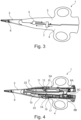
- FIG. 3 shows the bipolar HF instrument 1 in such a closed and locked state.
- the HF instrument 1 is in accordance with Fig. 1 and Fig. 2 shown, wherein the first instrument branch 3 and the second instrument branch 4 are completely closed.
- the locking device 8 is locked. In the locked state, the blade actuating element 5 and the RF activation element 7 are located almost in the middle between the two instrument branches 3 and 4 (ie essentially on the plane of symmetry of the instrument 1.
- FIG. 3 A solid arrow is shown pointing proximally from the blade actuating element 5. This arrow represents the direction of movement of the blade actuating element 5 to move the mechanical blade 6 for cutting.
- a dashed arrow pointing distally parallel to the solid arrow indicates the direction of the return path of the blade actuating element 5 to return the blade 6 to the rest position.
- a solid short arrow is shown in the proximal direction starting from the HF activation element 7. This arrow represents the direction of movement of the HF activation element 7 in order to activate the HF energy supply.
- Fig. 4 shows the bipolar HF instrument 1 with open instrument branches 3 and 4 in longitudinal section.
- the first instrument branch 3 and the second instrument branch 4 each consist of two half-handle shells, each enclosing a hollow space, whereby Fig. 4 the inner workings of the first and second instrument sectors 3 and 4 are visible.
- Fig. 4 shows the handle shell of the first instrument branch 3 with a first rack and pinion gear 9 with an input rack 10 and an output rack 11.
- the input rack 10 is connected to the blade actuating element 5 (in Fig. 4 not shown).
- the output rack 11 is connected to the mechanical blade 6 (in Fig. 4 not shown).
- the input rack 10 and the output rack 11 are connected to one another via an intermediate gear 12 in such a way that when the blade actuating element 5 is actuated by a user in the proximal direction, the mechanical blade 6 is moved distally from its proximal rest position in order to cut the tissue held in the jaw part 2.
- the rack and gear transmission 9 serves as a deflection mechanism in the first instrument branch 3.
- a return spring 5A is also provided for the protruding blade mechanism in such a way as to automatically force the blade actuating element 5 and thus the blade 6 back into their respective rest position.
- Fig. 4 shows the handle shell of the second instrument branch 4 with the interior of the HF activation element 7.
- an inner part 7A of the HF activation element 7 is indicated, which is arranged distally to a first HF activation button 15. If a second HF activation button 16 is provided, this is arranged laterally next to the first HF activation button 15 shown and is therefore in Fig. 4 not visible.
- the RF activation button 15 shown is arranged on a circuit board 17. If a first and a second RF activation button 15, 16 are provided, these are connected to one another via the circuit board 17 using an OR logic. There are two RF activation buttons in both the first and second In the first instrument branch 3 as well as in the second instrument branch 4, a flat plug 22 is provided in order to contact the HF strands of the jaw part 2.
- Fig. 4 the locking device 8 in longitudinal section.
- the locking device 8 has a male part 8A on the side of the first instrument branch 3 and a female part 8B on the side of the second instrument branch 4.
- the two parts 8A and 8B lock into one another.
- the locked state can be released again by means of a built-in return spring 8C.
- Fig. 5 shows the bipolar HF instrument 1 with open instrument branches 3 and 4 and the blade 6, whereby a part of the first instrument branch 3 and the jaw part 2 are hidden.
- Fig. 5 shows the same components as already Fig. 4 explained.
- the mechanical blade 6 is shown, which is arranged in the jaw part 2 and in the first instrument branch 3 and is connected to the output rack 10.
- Fig. 6 shows an HF activation element 7 according to a first embodiment not belonging to the invention.
- the HF activation element 7 has an inner part in the form of a crossbar 7A, which connects a first actuating wing or button 7B and a second actuating wing or button 7C to one another.
- one end of the crossbar-shaped inner part 7A is glued and/or pressed into/on the first actuating wing 7B or the second actuating wing 7C.
- the first actuating wing 7B and the second actuating wing 7C are arranged outside and laterally, ie on the opposite or opposite sides of the second instrument branch 4.
- the inner part 7A is located in the interior of the second instrument branch 4.
- a contacting element 13 with an activation surface 14 is attached to a central section of the inner part 7A. If the user activates the HF activation element 7, the contacting element 13 connected to the inner part 7A presses the activation surface 14 onto the HF activation button 15 (in Fig. 6 not shown) and the RF energy delivery is activated.
- the contacting element 13 is formed and attached on a central axis 19 of the HF activation element 7, i.e. centrally on the inner part 7A in a T-shape, as already indicated above.
- the activation surface 14 is arranged on the side of the contacting element 13 facing the HF activation button 15.
- the HF activation element 7 is mounted in a rocking manner along the central axis 19 in the second instrument branch 4, such that the two actuation wings 7B and 7C protrude laterally on the second instrument branch and can thus be reached and actuated equally well from both sides of the instrument 1.
- Fig. 7 shows the RF activation element 7 according to the first embodiment.
- a crossbar-shaped inner part 7A of the HF activation element 7 is shown with a first actuating wing 7B and a second actuating wing 7C.
- a contacting element 13 with the activation surface 14 is attached to or formed on the inner part 7A in the center of the inner part 7A of the HF activation element 7 in the direction of a first and a second HF activation button 15.
- a first and a second RF activation button 15, 16 are provided, which are arranged next to each other and in Fig. 7 below the activation surface 14, ie according to the Fig. 5 are arranged proximal to the activation surface 14.
- Both HF activation buttons 15, 16 are arranged on a (single) circuit board 17.
- Two connections 23 are provided on the circuit board 17, which serve for the energy supply.
- the activation surface 14 presses on one of the two HF activation buttons 15, 16, whereby the HF current is released to the electrodes in the jaw part 2.
- Fig. 8 shows an RF activation element 7 according to a second embodiment of the invention.
- the second embodiment corresponds almost to the first embodiment, with the difference that the contacting element 13 is formed with two cam-shaped projections arranged next to one another, which surround the RF activation switch 7 on the outside (without contact), so that the Contacting element 13 or its projections come into contact with the HF activation button 15 when the HF activation element 7 is actuated with a corresponding rocker movement of the crossbar-shaped inner part 7A. Due to the double cam-shaped contacting element 13, exactly one electronic HF activation button 15 is sufficient and contact of the activation surface 14 on the side facing the HF activation button 15 with the HF activation button 15 is ensured.
- two return springs 7D are provided which are spaced apart in the transverse direction of the instrument and are supported on the one hand on the second instrument branch 4 and on the other hand on the crossbar-shaped inner part 7A in order to force the HF activation element 7 back into the (contactless) starting position regardless of which side of the instrument 1 the HF activation element 7 is actuated from.
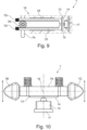
- Fig. 9 shows an HF activation element 7 with a second rack and pinion gear 18 according to a third embodiment not belonging to the invention.
- the second rack and pinion gear 18 has a first rack 24 and a second rack 25, which are opposite one another and are operatively connected to one another at distal end sections via a gear 26.
- a return spring 7D acting in the proximal direction is attached to both the first rack 24 and the second rack 25.
- a contacting element 13 with an activation surface 14 in the direction of an HF activation button 15 arranged proximal to the HF activation element 7 is provided.
- the HF activation button 15 is arranged on a circuit board 17. This means that the protruding rack and pinion gear 18 is provided in the second instrument branch 4 in such a way that the HF activation button 15 is arranged in the proximal direction to the rack and pinion gear 18. Finally, an actuating element 7A in the form of a crossbar is shown, which protrudes from one side of the second instrument branch and which is connected to the pinion. Another, identically constructed Actuating element (not further shown) is also connected to the gear and protrudes from the second instrument branch on the opposite side.
- Fig. 10 shows an RF activation element 7 as a slider according to a fourth embodiment not belonging to the invention.
- the fourth embodiment is according to Fig. 8 formed, wherein the contacting element 13 with the activation surface 14 is formed flat instead of cam-shaped.
- the crossbar-shaped inner part 7A is not rocker-shaped as in the embodiment according to Fig. 8 , but is mounted so that it can be moved longitudinally in the second instrument branch 4.
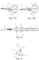
- Figs. 11A and 11B and 12 show the HF instrument 1 with a lever 27 as the HF activation element 7 on the opposite sides of the instrument.
- Fig. 11A the HF instrument 1 is aligned in accordance with the above figures.
- Fig. 11B the orientation of the HF instrument 1 is reversed, i.e. the first instrument branch 3 is shown in the downward direction and the second instrument branch 4 is shown in the upward direction, so that both levers 27 can be shown on the opposite sides of the instrument. Due to the almost central arrangement of the HF activation element 7 on the first On the side of the second instrument branch 4 closest to the instrument branch 3, the operation of the lever 27 is the same regardless of the orientation of the HF instrument 1.
- Fig. 13 shows the arrangement of two HF activation buttons 15 and 16 and the lever 27 as HF activation element 7 according to the sixth embodiment in the context of a schematic diagram.
- the levers 27 are connected in a rotationally fixed manner to a contact rod which extends along the second instrument branch 4, preferably in the proximal direction.
- a first HF activation button 15 and a second HF activation button 16 are provided, which are arranged opposite one another in such a way that the contact rod is initially held between them without contact.
- the one lever 27 shown in solid line is in a first position (1), in which the contact rod has no contact with the HF activation buttons 15 and 16, and is actuated anti-clockwise from this position, the first activation button 15 is pressed by the contact rod.
- the lever 27 shown in dashed lines in its second position (2) comes into the same spatial position as the lever 27 shown in solid line in Fig. 13 , whereby in this case the two HF activation buttons 15 and 16 are consequently located above the lever 27. If this lever 27 shown by a dashed line is now operated anti-clockwise, the contact rod comes into contact with the second HF activation button 16 and this is consequently pressed.
- lever 27 it is also possible for the two levers 27 to swap their respective positions shown. In this case, switching from position (1) to position (2) is preferably realized by a snap mechanism between lever 27 and contact rod so that the lever noticeably engages in the defined positions (not shown).
- Figs. 14 and 15 show the bipolar HF instrument 1 with an HF activation element 7 according to a defined safety concept.
- the HF instrument 1 is in Fig. 14 closed and not locked.
- Fig. 15 the HF instrument 1 is closed and locked.
- the inner part 7A of the HF activation element 7 is supported by a spring element 7E, preferably a compression spring.
- the spring element 7E is arranged in such a way that the entire HF activation element 7 protrudes a little in the axial direction of its rotation/rocking axis 19 from the instrument branch 4 or is displaced in the axial direction of its rotation/rocking axis 19. This has Fig. 14
- the result is that the activation surface 14, which is supposed to press on the first HF activation button 15, can no longer be brought into active engagement with the HF activation button 15.
- the HF activation element 7 is actuated in this shifted position, no HF energy can be activated.
- This security or safety concept therefore basically provides for a spring-force-induced displacement of the HF activation element 7 into a non-functional position, which is only canceled again when the two instrument branches 3, 4 are fully closed, by the other, first instrument branch 3 pushing the HF activation element 7 back into its functional position.
- Figs. 16 and 17 show the HF instrument 1 with an HF activation element locking element 28 as another security or safety concept.
- an HF activation element locking element 28 is built into/integrated in the HF instrument 1.
- the user is able to operate it in a closed and locked state, provided he triggers the HF activation element locking element 28 accordingly.
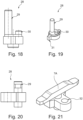
- the activation element locking element 28 according to Figs. 18 and 19 has a plunger 29 which protrudes from the handle shell of the second instrument branch 4 and can be brought into contact with the opposite handle shell of the first instrument branch 3 when the HF instrument 1 is closed.
- a pin 30 Next to the plunger 29 there is a pin 30.
- the pin 30 interacts with a bore 32 according to Fig. 21 in the inner part 7A of the HF activation element 7.
- the pin 30 In an open state of the HF instrument 1 according to Fig. 16 the pin 30 is in the hole 32 and turning/ rocking/ actuating the HF activation element 7 is not possible.
- a closed state of the HF instrument 1 according to Fig. 17 the pin 30 is pushed out of the bore 32 by the plunger 29 and the turning/rocking/operating of the HF activation element 7 is possible.
- guide elements 31 in the form of sliding tabs according to Fig. 19 which are slide-mounted in corresponding guide grooves in the second instrument branch 4. This ensures that when the instrument is opened, the pin 30 can move into the bore 32.
- Fig. 22 shows the distances between the individual components of the HF instrument 1.
- the HF activation element 7 and the blade actuation element 5 are placed at a sufficient distance from one another. It is preferred if the distance from the center of the instrument actuation eyelet 20 to the center of the blade actuation element 5 is preferably between 56 and 96 mm, more preferably between 66 and 86 mm and more preferably 76 mm. It is also preferred if the distance from the center of the instrument actuation eyelet 20 to the center of the HF activation element 7 is preferably between 22 and 62 mm, more preferably between 32 and 52 mm and more preferably 42 mm.
- Fig. 23 shows the RF activation element 7 with a seal 33.
- Fig. 23 shows the HF instrument 1 according to the above descriptions, wherein the HF activation element 7 and the first and/or second HF activation button 15 and/or 16 are sealed with a TPE seal 33.
- Fig. 24 shows an HF activation button 15 or 16, wherein the HF activation button 15 or 16 is already sealed or encapsulated at the factory by means of a casing which has a concave, preferably hemispherical protuberance in the contact area of the HF activation button.
- the protruding hemisphere 35 which the activation surface 14 presses on when the HF activation element 7 is actuated, is touched, the HF energy is supplied.
- Fig. 25 shows the RF activation element 7 according to Fig. 6 with a sealing ring 34.
- the sealing ring 34 is placed around the T-shaped contacting element 13 on the side towards the inner part 7A of the HF activation element 7, so that the crossbar-shaped inner part 7A and the contacting element 13 including the contact surface 14 can be separated from one another in a fluid-tight manner.
- the sealing ring 34 is preferably an elastomer sealing ring/O-ring.
- Fig. 26 and 27 show a further alternative embodiment of the HF instrument 1.
- the HF instrument 1 is designed according to the previous figures, wherein the HF activation element 7 is present in duplicate.
- the two HF activation buttons 7 are in this case located on the top of the respective instrument branches 3 and 4, i.e. on the top and bottom of the instrument, whereas the blade actuating element 5 remains on the left and right sides of the instrument in accordance with the previously described embodiments.
- Fig. 27 The locking device 8, in particular the male part 8A, is also shown, which can be switched on by means of a rotary lever 36 at the proximal end of the HF instrument 1.
- an additional control device 37 in the form of a button is provided.
- the control device 37 is connected in an AND logic with the HF activation buttons 15 and/or 16 and must be permanently actuated in order to activate HF energy.
Landscapes
- Health & Medical Sciences (AREA)
- Surgery (AREA)
- Engineering & Computer Science (AREA)
- Life Sciences & Earth Sciences (AREA)
- Biomedical Technology (AREA)
- Otolaryngology (AREA)
- Nuclear Medicine, Radiotherapy & Molecular Imaging (AREA)
- Plasma & Fusion (AREA)
- Physics & Mathematics (AREA)
- Heart & Thoracic Surgery (AREA)
- Medical Informatics (AREA)
- Molecular Biology (AREA)
- Animal Behavior & Ethology (AREA)
- General Health & Medical Sciences (AREA)
- Public Health (AREA)
- Veterinary Medicine (AREA)
- Surgical Instruments (AREA)
Description
- Die vorliegende Offenbarung betrifft ein (medizinisches) bipolares HF-Instrument vorzugsweise der Scheren- oder Zangenbauart mit einer ersten und einer zweiten (in einem Scharnier sich kreuzenden) Instrumentenbranchen, die an einem distalen Instrumenten-Endabschnitt ein Maulteil beispielsweise zum Fassen von Gewebe und an einem proximalen Instrumenten-Endabschnitt Halte-/Betätigungsgeometrien (Griffe, Fingerringe, etc.) ausbilden oder aufweisen, welche sämtlich dazu vorgesehen und ausgebildet sind, sich beim Öffnen voneinander weg und beim Schließen aufeinander zu zubewegen zum manuellen Schneiden und (HF-) Versiegeln von Gewebe insbesondere in der offenen Chirurgie.
- Im Allgemeinen sind chirurgische Versiegelungs- und Schneideinstrumente der vorstehenden Gattung bekannt, welche einen hochfrequenten (HF) Strom für die Versiegelung mittels bipolarer Technik und eine mechanische Klinge für den Schnitt von (biologischem) Gewebe verwenden. Hierbei ist eine automatische Daueraktivierung beim Zusammendrücken der Branchen vorgesehen. Häufig ist eine Klingenverriegelung im offenen Zustand der Branchen als Sicherheitsvorkehrung in das Instrument integriert. Ein des Weiteren vorgesehener HF-Taster vermittelt in der Regel ein taktiles Feedback in zwei Stufen (2-Klick-Taster). Bei einem ersten Klick wird einem Anwender ein Hinweis gegeben, dass ein definierter Schließ-Zustand erreicht ist und bei einem zweiten Klick wird der HF-Strom aktiviert. Mit diesem chirurgischen Instrument aus dem Stand der Technik ist eine schnelle Arbeitsweise möglich, insbesondere für erfahrene Anwender. Das chirurgische Instrument weist klar getrennte Funktionen zum Schneiden und Versiegeln auf sowie geringe Herstellungskosten.
- Alternativ gibt es ein chirurgisches Instrument, welches Ultraschall für die Versiegelung und den Schnitt verwendet, wobei die Versiegelung und der Schnitt manuell dauer-aktivierbar sind. Ferner bietet dieses chirurgische Instrument die Wahl zwischen einem MIN- oder einem MAX-Modus an dem Instrument. Es ist von Vorteil, dass beim Schließen keine ungewollte Aktivierung möglich ist, insbesondere da der Anwender freie Auswahl hat und dadurch mehr Kontrolle und Sicherheit gegeben ist.
- Die bekannten chirurgischen Instrumente haben jedoch den Nachteil, dass ein permanentes Halten des HF-Tasters notwendig ist und dies für einen Anwender auf Dauer unergonomisch und ermüdend sein kann, insbesondere, da mehrere Aktivierungen pro Operation denkbar sind. Ein weiterer Nachteil kann die Variation des aufgebrachten Drucks sein. Der Anwender kann nämlich durch seine Handkraft den Betätigungsdruck auf das Instrument/dessen Branchen variieren und somit ggf. das Versiegelungsergebnis negativ beeinflussen. Eine versehentliche HF-Aktivierung bei zu schnellem Zusammendrücken sowie eine bevorzugte Ausrichtung bei der Handhabung aufgrund der asymmetrischen Anordnung des Klingenbetätigungselements sind weitere Nachteile.
- Die
US 10 188 450 B2 - Die
US 10 660 694 B2 - Aus der
EP 2 671 528 B1 und derEP 2 436 330 B1 ist ein bipolares elektrochirurgisches Instrument bekannt, mit einem ersten und einem zweiten Schaft (Branche), der jeweils ein Backenelement aufweist, das sich von seinem distalen Ende erstreckt. Jedes Backenelement ist angepasst, um eine Verbindung mit einer Quelle elektrochirurgischer Energie herzustellen, so dass die Backenelemente in der Lage sind, Energie selektiv durch das dazwischen gehaltene Gewebe zu leiten. Ein Messerkanal ist so konfiguriert, dass er einen Schneidmechanismus darin hin- und her bewegt. Ein Aktuator schiebt selektiv den Schneidemechanismus vor. Ein Schalter ist an der ersten Welle angeordnet und konfiguriert, um zwischen einer ersten Position und mindestens einer nachfolgenden Position bei einem Vorspanneingriff mit einer mechanischen Schnittstelle, die an der zweiten Welle angeordnet ist, niedergedrückt zu werden. Die erste Position des Schalters leitet Informationen an den Benutzer weiter, die einem gewünschten Druck auf das Gewebe entsprechen, und die mindestens eine nachfolgende Position ist konfiguriert, um die Quelle elektrochirurgischer Energie zu aktivieren, um den Backenelementen elektrochirurgische Energie zuzuführen. - Die
US 7 253 667 B2 ,US 9 498 279 B2 US 2019 0356 952 A1 ,WO 2019 224 634 A1 ,EP 1 609 430 B1 ,US 2019 0357 969 A1 ,WO 2019 224 636 A3 ,US 2019 0357 967 A1 undWO 2019 224 637 A1 beschreiben ebenfalls gattungsgemäße elektrochirurgische Instrumente nach dem einleitenden Teil des Anspruchs 1. Dabei offenbart die oben genannteWO 2019 224 634 A1 beidseitige Bedienmöglichkeiten. - Der vorliegenden Offenbarung liegt die Aufgabe zugrunde, ein bipolares HF-Instrument bereitzustellen, welches eine vereinfachte Bedienung, insbesondere über einen längeren Zeitraum ermöglicht, und ferner die Ausrichtung des Instruments zur Verwendung irrelevant ist. Ferner ist es insbesondere ein Ziel der vorliegenden Offenbarung, die vorstehenden Nachteile aus dem Stand der Technik zu beseitigen oder zumindest zu verbessern.
- Diese Aufgabe wird gelöst durch ein bipolares HF-Instrument mit den Merkmalen des Anspruchs 1.
- Demnach hat das bipolare HF- (Hand-Instrument ein Maulteil (zum Fassen! Festhalten! Greifen von Gewebe), sowie eine erste Instrumentenbranche und eine zweite Instrumentenbranche (zum manuellen Betätigen des Maulteils), welche (sämtlich) dazu vorgesehen und ausgebildet sind, sich beim Öffnen voneinander weg und beim Schließen aufeinander zu zubewegen. Darüber hinaus ist ein Klingenbetätigungselement/ Klingenbetätigungshebel oder (Schiebe-)Taste zum Aktivieren einer in dem Maulteil gelagerten mechanischen Klinge zum Schneiden von Gewebe vorgesehen, wobei die mechanische Klinge dazu vorgesehen und ausgebildet ist, um mittels des Klingenbetätigungselements von einer ersten Position (Park-/Nicht-Schneideposition) in eine zweite Position (Schneideposition) bewegbar zu sein. Des Weiteren ist ein HF-Aktivierungselement oder Aktivierungstaste/-knopf/ -schalter zum Aktivieren/Freischalten einer HF-Stromzufuhr insbesondere zum Versiegeln (Koagulieren) von Gewebe und ggf. eine, vorzugsweise separat dazu ausgebildete, sowie auf die Branchen einwirkende Einrastvorrichtung vorgesehen, um (wahlweise) einen eingerasteten Branchenzustand bei geschlossenen Instrumentenbranchen zu erreichen.
- Der Grundgedanke der vorliegenden Offenbarung besteht nunmehr darin, dass das HF-Aktivierungselement und vorzugsweise das Klingenbetätigungselement derart vorgesehen und ausgebildet sind, um jeweils von zwei, vorzugsweise jeweils sich gegenüberliegenden (bzw. voneinander abgewandten) Seiten des HF-Instruments in weiter vorzugsweise gleicher oder gleichartiger Weise bedienbar zu sein. Dies hat den Vorteil, dass die mechanische Klinge, egal wie herum bzw. in welcher Hand das Instrument gehalten wird, immer gleichartig betätigt werden kann. Demnach gibt es keine bevorzugte Ausrichtung bzw. Haltung des Instruments. Dies gilt ebenso für die Handhabung als Rechts- oder Linkshänder. In anderen Worten, ist es irrelevant, wie ein Anwender das bipolare HF-Instrument in die Hand nimmt, da die Bedienung durch die beidseitige Ausbildung des Klingenbetätigungselements als auch des HF-Aktivierungselements immer in der gleichen Weise funktioniert.
- In anderen Worten handelt es sich beim vorliegenden Gegenstand gemäß der Offenbarung um ein chirurgisches (Hand-Instrument der Scheren- oder Zangenbauart mit bipolarer HF-Technologie und mechanischer (Gewebeschneid-)Klinge. Durch das Öffnen und Schließen der Instrumentenbranchen wird das Maulteil ebenfalls geöffnet und geschlossen. Im geschlossenen Zustand kann Gewebe gefasst und mittels HF (hochfrequenter Energiezufuhr) über im Maulteil angeordneter Elektroden versiegelt werden. Mit dem Maulteil sind zudem Präparation und Manipulation an dem Gewebe möglich. Im geschlossenen Zustand des Maulteils kann das Gewebe mittels der im Maulteil gelagerten Klinge ebenfalls geschnitten werden. Die Betätigungseinrichtungen zur separaten und individuellen manuellen Betätigung der HF-Stromzufuhr und der Klinge sind derart ausgebildet und angeordnet, dass sich auf zwei jeweils gegenüberliegenden bzw. voneinander abgewandten Seiten des Instruments im Wesentlichen die gleiche Betätigungsgeometrie ergibt mit im Wesentlichen der gleichen Funktion/Wirkung auf die HF-Stromzufuhr und die Klinge. Hierfür wird ausdrücklich darauf hingewiesen, dass die vorstehend beschriebene Spiegelung der Betätigungsgeometrie nicht notwendiger Weise nur zweidimensional, sondern auch dreidimensional erfolgen kann. In anderen Worten ausgedrückt können beide Betätigungseinrichtungen zur Betätigung von HF-Strom und Klinge beispielsweise links und rechts des Instruments im Wesentlichen gleich (spiegelbildlich) angeordnet sein (zweidimensionale Duplikation) oder nur die eine Betätigungseinrichtung (ggf. Klingenbetätigung) links und rechts des Instruments und die andere Betätigungseinrichtung (ggf. HF-Stromzufuhr) oben und unten des Instruments (jeweils spiegelbildlich) angeordnet sein (dreidimensionale Duplikation).
- Die mechanische Klinge ist mittels des Klingenbetätigungselements von einer ersten Position in eine zweite Position beweglich. Das Klingenbetätigungselement wird dabei linear von dessen distaler Ruhe-Parkposition nach proximal bewegt. Die mechanische Klinge bewegt sich entsprechend linear von dessen proximaler Ruheposition nach distal und kann so im Maulteil gefasstes Gewebe schneiden.
- Weiterhin hat das Instrument bevorzugt eine fest eingebaute Einrastvorrichtung in Form einer Durchlaufsperre. Mit Hilfe der Raste können die Instrumentenbranchen in einem definierten Zustand (Relativposition) arretiert werden. Zum Einrasten werden die Instrumentenbranchen geschlossen, bis der eingerastete Zustand erreicht wird. Zum Ausrasten werden die Branchen wieder etwas zusammengedrückt, bis sich die Raste löst. Die Gestaltung der Einrastvorrichtung/ Raste/ Durchlaufsperre ist aus dem Stand der Technik hinlänglich bekannt und muss daher nicht weiter beschrieben werden. Sie hat den wesentlichen Vorteil, dass mit derer Hilfe ein definierter Schließzustand erzeugbar ist, bei dem Schwankungen der Schließkraft nur in geringem Maße zu erwarten sind. Dies wiederum hat den Vorteil, dass die Versiegelungsqualität erhöht bzw. eine konstante Performance sichergestellt ist. Zudem ermöglich die Einrastvorrichtung dem Anwender, Gewebe sicher zu halten, ohne dass dieser eine HF-Aktivierung auslöst. Ein weiterer Vorteil ist, dass der Anwender bei geschlossener Raste seine Hand entspannen kann. Es ist kein permanentes Zusammendrücken des Instruments notwendig. Damit ist diese Offenbarung besonders ergonomisch.
- Weitere Aspekte der vorliegenden Offenbarung sind nachfolgend gemäß den Unteransprüchen beschrieben.
- Es ist von Vorteil, wenn die Einrastvorrichtung aus einem männlichen Teil und einem weiblichen Teil besteht. In anderen Worten kann im geschlossenen und eingerasteten Zustand HF aktiviert und geschnitten werden. In der Regel wird zuerst HF aktiviert und eine Versiegelung durchgeführt. Hierzu wird das HF-Aktivierungselement nach proximal bewegt. Es ist bevorzugt eine Tipp-Aktivierung vorgesehen, sodass der Anwender nur einmalig den Taster/Knopf betätigen muss und diesen nicht permanent halten muss. Ein HF-Generator übernimmt mit seinem integrierten Algorithmus die Logik und schaltet nach einer erfolgreichen Versiegelung selbständig aus. Der Anwender hat jedoch immer die Möglichkeit, durch eine erneute Tipp-Aktivierung des HF-Aktivierungstasters/-knopfs den Prozess der Versiegelung zu stoppen. In einem zweiten Schritt kann geschnitten werden. Hierzu wird das Klingenbetätigungselement nach proximal gezogen. Sowohl das HF-Aktivierungselement als auch das Klingenbetätigungselement werden automatisch zurückgestellt, vorzugsweise durch Federn.
- Es ist bevorzugt, wenn die Funktionen der Versiegelung und/oder des Schneidens unabhängig voneinander benutzbar sind. In anderen Worten hat der Anwender die Freiheit, die Funktionen Versiegeln und/ oder Schneiden unabhängig voneinander zu benutzen.
- Es ist bevorzugt, wenn in der ersten Instrumentenbranche ein erstes Zahnstangen-Zahnrad-Getriebe vorgesehen und angeordnet ist, bei welchem eine Input-Zahnstange mit dem Klingenbetätigungselement und eine Output-Zahnstange mit der mechanischen Klinge verbunden ist, wobei das Klingenbetätigungselement linear von einer distalen Ruheposition nach proximal bewegbar ist. In anderen Worten ist die dafür benötigte Umlenkmechanik in der ersten Instrumentenbranche ein Zahnstangen-Zahnrad-Getriebe, bei dem die Input-Zahnstange an dem Klingenbetätigungselement und die Output-Zahnstange an der mechanischen Klinge befestigt ist.
- Es ist von Vorteil, wenn die Input-Zahnstange und das damit verbundene Klingenbetätigungselement annähernd auf der Symmetrie-Ebene zwischen der ersten Instrumentenbranche und der zweiten Instrumentenbranche angeordnet sind.
- In anderen Worten stellt die Funktionsweise mit dem Zahnstangen-Zahnrad-Getriebe einen wesentlichen Vorteil für die symmetrische Nutzung des Instruments dar. Die Anordnung der Input-Stange und des damit verbundenen Klingenbetätigungselements annähernd auf der Symmetrie-Ebene zwischen erster und zweiter Instrumentenbranche bringt den großen Vorteil, dass die Klinge, egal wie herum das Instrument gehalten wird, immer gleich betätigt werden kann. Es gibt keine bevorzugte Ausrichtung bzw. Haltung des Instruments in dieser Hinsicht. Dies gilt ebenso für die Handhabung als Rechts- oder Linkshänder.
- Es ist bevorzugt, wenn das bipolare HF-Instrument zudem eine Klingenverriegelung hat, welche derart konfiguriert ist, um in einem offenen Zustand die Betätigung der mechanischen Klinge zu blockieren und dass in einem definierten Schließzustand die mechanische Klinge beweglich ist. Hierbei sind zwei verschiedene Sicherheitskonzepte vorgesehen, welche in das bipolare HF-Instrument implementierbar sind.
- In einem ersten Sicherheitskonzept ist vorgesehen, dass eine Klingenbetätigung möglich ist, sobald die Maulteile ausreichend geschlossen sind, beispielsweise, wenn sie sich berühren. Eine HF-Aktivierung/-Betätigung ist prinzipiell immer möglich. Das heißt, es gibt keine Verriegelung des HF-Aktivierungselements. Hierbei ist alternativ vorgesehen, dass HF aktiviert werden kann, wenn das Instrument nicht eingerastet ist. Dies ermöglich dem Anwender mehr Anwendungsmöglichkeiten, birgt aber auch das Risiko, dass es zu einer HF-Aktivierung mit nicht ausreichender Schließkraft kommt. Hierbei ermöglicht die feste Einrastvorrichtung einen definierten Schließzustand.
- In einem zweiten Sicherheitskonzept ist sowohl die Klingenbetätigung als auch die HF-Betätigung nur möglich, wenn sich das Instrument in der eingerasteten Position der fest eingebauten Einrastvorrichtung befindet. Dies stellt sicher, dass sowohl ein Schnitt als auch eine HF-Versiegelung nur in einem klar definierten Schließzustand möglich sind und gewährleistet maximale Sicherheit. Diese Option schränkt den Anwender jedoch in seinen Möglichkeiten ein. Besonders erfahrene Anwender könnten dieses Sicherheitskonzept als starke Limitierung wahrnehmen. Daher ist es bevorzugt, wenn das erste Sicherheitskonzept für erfahrene Anwender und das zweite Sicherheitskonzept für weniger erfahren Anwender verwendet wird.
- Bevorzugter Weise ist das HF-Aktivierungselement derart ausgebildet und vorgesehen, um bei Durchführung einer Versiegelung nach proximal bewegbar oder verschwenkbar oder verschiebbar zu sein.
- Es ist vorteilhaft, wenn das HF-Aktivierungselement derart ausgebildet und vorgesehen ist, um nach einer ersten Tipp-Aktivierung die HF-Stromzufuhr zu aktivieren und automatisch, vorzugsweise mittels eines integrierten Algorithmus, nach erfolgreicher Versiegelung auszuschalten oder um nach einer zweiten Tipp-Aktivierung des HF-Aktivierungselements vor erfolgreicher Versiegelung, die HF-Stromzufuhr manuell zu stoppen.
- Erfindungsgemäß hat das HF-Aktivierungselement einen Innenteil, der wippend, schiebbar oder verschwenkbar auf einer Drehachse des HF-Aktivierungselements in der zweiten Instrumentenbranche orthogonal zu der proximal-distal-Richtung gelagert ist, wobei die in Richtung proximal des Instruments weisende Seite des Innenteils ein Kontaktierungselement mit einer Aktivierungsfläche aufweist, welche einen ersten HF-Aktivierungstaster bei Betätigung des HF-Aktivierungselements kontaktiert und die HF-Stromzufuhr aktiviert.
- In anderen Worten verfolgt die Gestaltung und Positionierung des HF-Betätigungstasters ebenfalls das Ziel, die Bedienung des Instruments vollsymmetrisch zu ermöglichen, bzw. die Notwendigkeit einer bevorzugten Ausrichtung des Instruments zu vermeiden.
- Gemäß einer ersten bevorzugten Ausführungsform ist das HF-Aktivierungselement um eine Achse herum wippend in der zweiten Branche gelagert und kann von beiden Seiten des Instruments gleich gut erreicht werden. Ferner bringt die Positionierung des HF-Aktivierungselements in nur einer Instrumentenbranche den Vorteil, dass sich die Verkabelung der HF-Aktivierung ebenfalls nur in einer Instrumentenbranche befindet. Dies reduziert den Aufwand und die Kosten gegenüber einem Konzept mit Betätigungstastern/HF-Aktivierungsknöpfen in beiden Instrumentenbranchen signifikant.
- Erfindungsgemäß hat der Innenteil des HF-Aktivierungselements einen ersten Flügel und einen zweiten Flügel, wobei der erste Flügel seitlich an der zweiten Instrumentenbranche hervorsteht und der zweite Flügel dem ersten Flügel gegenüberliegend auf der anderen Seite der zweiten Instrumentenbranche hervorsteht.
- In anderen Worten besteht das HF-Aktivierungselement aus mehreren Teilen, einem Innenteil und einem ersten sowie einem zweiten Flügel. Alternativ ist unter anderen Montagebedingungen auch eine einteilige Ausführung denkbar.
- Alternativ ist es denkbar, das HF-Aktivierungselement als Schieber zu gestalten, der in proximaler und distaler Richtung linear bewegbar ist. Hierzu ist es vorteilhaft, wenn das HF-Aktivierungselement in beispielsweise einem Schlitz in einem Gehäuse der zweiten Instrumentenbranche beweglich geführt ist. Dies hat den Vorteil, dass genau ein elektronischer HF-Aktivierungstaster notwendig ist.
- Die Aktivierungsfläche des HF-Aktivierungselements gemäß der vorstehenden Ausführungsform ist dazu vorgesehen, auf den ersten (elektronischen) HF-Aktivierungstaster zu drücken.
- Erfindungsgemäß ist das Kontaktierungselement nockenförmig in Richtung hin zu dem ersten HF-Aktivierungstaster vorgesehen und ausgebildet.
- Bei einem alternativen nicht zur Erfindung gehörenden Beispiel ist ein zweites Zahnstangen-Zahnrad-Getriebe derart in Richtung distal zu dem ersten HF-Aktivierungstaster platziert, um diesen bei Betätigung des HF-Aktivierungselements mit der Aktivierungsfläche zu kontaktieren.
- In anderen Worten ist eine alternative Ausführungsform mit genau einem elektronischen HF-Aktivierungstaster möglich. Hierzu weist der Innenteil des HF-Aktivierungselements eine Art Nocke oder ähnliches auf, die bei der Rotation/Verschwenkung um die Drehachse des HF-Aktivierungselements in Eingriff mit dem ersten HF-Aktivierungstaster kommt. Hierbei ist eine zusätzliche Rückstellfeder vorgesehen und ggf. notwendig.
- Eine alternative nicht zur Erfindung gehörende Ausführungsform bei Verwendung (genau) eines ersten HF-Aktivierungstasters ist mit einem Zahnstangen-Zahnrad-Getriebe vorgesehen. Dabei ist das Innenteil des HF-Aktivierungselements ebenfalls drehbar gelagert und mit einem Zahnrad verbunden. Auf zwei Seiten des Zahnrades sind entsprechend zwei Zahnstangen platziert, die jeweils ihre Bewegung auf ein Kontaktierungselement/ Aktivierungselement/ eine Druckplatte übertragen können. Das Kontaktierungselement betätigt dann den ersten HF-Aktivierungstaster. Je nach Ausführung des HF-Aktivierungstasters ist das Kontaktierungselement überflüssig und die Zahnstangen können direkt auf den HF-Aktivierungstaster drücken. Um eine zuverlässige Funktion zu ermöglichen, ist es von Vorteil, wenn die Zahnstangen mit Rückstellfedern versehen sind.
- Es ist vorteilhaft, wenn ein zweiter HF-Aktivierungstaster neben dem ersten HF-Aktivierungstaster parallel zu dem Innenteil des HF-Aktivierungselements vorgesehen und angeordnet ist. In anderen Worten übt die Aktivierungsfläche des Kontaktierungselements durch das Verdrehen/ Verschwenken/ Verschieben des HF-Aktivierungselements eine Kraft auf einen der beiden HF-Aktivierungstaster aus und löst damit eine Aktivierung des HF-Prozesses aus. Durch erneutes Verdrehen/ Verschwenken/ Verschieben des HF-Aktivierungselements kann der HF-Prozess bei Bedarf auch manuell gestoppt werden. Neben der vollsymmetrischen Gestaltung hat die vorstehende Ausführungsform den Vorteil, dass das HF-Aktivierungselement sowohl durch Ziehen als auch durch Drücken betätigbar ist/betätigt werden kann. Dies eröffnet dem Anwender mehrere ergonomische Bedien-Optionen.
- Es ist bevorzugt, wenn eine Rückstellung in eine nicht betätigte Ruheposition über eine integrierte Feder in den HF-Aktivierungstastern vorgesehen ist. Alternativ dazu kann eine zusätzliche Rückstellfeder in Form einer Blech-/Blattfeder, einer Torsionsfeder oder ähnlichem erfolgen.
- Es ist demnach vorteilhaft, wenn das Innenteil des HF-Aktivierungselements mit einem Federelement, beispielsweise einer Druckfeder, unterbaut ist. Dies hat den Vorteil, dass das Federelement bewirkt, dass das gesamte HF-Aktivierungselement ein Stück weit in Axialrichtung seiner Drehachse herausragt. Dies hat zur Folge, dass die Aktivierungsfläche, die auf den ersten und/ oder zweiten HF-Aktivierungstaster drücken würde, außer Eingriff gebracht ist und beim Betätigen des HF-Aktivierungselements in dieser Position also keine HF-Energiezufuhr aktivierbar ist. In einem geschlossenen Zustand wird das HF-Aktivierungselement in der zweiten Instrumentenbranche gedrückt. In dieser Position wird die Aktvierungsfläche durch Schließen der ersten und zweiten Instrumentenbranchen und das dadurch bedingte Zusammendrücken der Druckfeder in die zweite Instrumentenbranche wieder in Eingriff gebracht mit dem ersten und/oder zweiten HF-Aktivierungstaster. Hierbei ist es von Vorteil, wenn das HF-Aktivierungselement eine separate Rückstellfeder besitzt, die diesen permanent in eine Ruhestellung drängt, bei der die Flügel des HF-Aktivierungselements senkrecht zur Hauptebene des Instruments stehen. Als Rückstellfeder kann eine Blattfeder, Zugfeder, Torsionsfeder, oder ähnliches genommen werden.
- Es ist von Vorteil, wenn für den ersten HF-Aktivierungstaster und/ oder den zweiten HF-Aktivierungstaster ein handelsüblicher elektronischer Taster verwendbar ist.
- Es ist bevorzugt, wenn der erste HF-Aktivierungstaster und/oder der zweite HF-Aktivierungstaster in proximaler Richtung weg von dem Innenteil des HF-Aktivierungselements diesem jedoch zugewandt auf einer Platine in der zweiten Instrumentenbranche angeordnet ist/ sind. In anderen Worten ist es bevorzugt, dass sich der erste HF-Aktivierungstaster und/ oder zweite HF-Aktivierungstaster auf einer Platine befinden, auf welcher sie in einer ODER-Logik miteinander verschaltet sind. So ist gewährleistet, dass egal welcher der HF-Aktivierungstaster gedrückt wird, eine Aktion erfolgt.
- Alternativ ist es bevorzugt, wenn das HF-Aktivierungselement hebelartig ausgeführt ist. Hierbei ist es vorgesehen, dass die Position eines derartigen Hebels umschaltbar ist, sobald das bipolare HF-Instrument gedreht wird, sodass auch eine vollsymmetrische Betätigung des Instruments möglich ist. Daher befindet sich der Hebel auf beiden Seiten des Instruments bzw. der zweiten Instrumentenbranche. Diesbezüglich ist es vorteilhaft, wenn in der Instrumentenbranche bzw. in dem Gehäuse der Instrumentenbranche ein erster und ein zweiter HF-Aktivierungstaster vorgesehen! platziert sind, welche sich derart gegenüberstehen, dass, wenn sich der Hebel in einer ersten Position befindet, der erste HF-Aktivierungstaster bei Betätigung gedrückt wird, und wenn sich der Hebel in Position 2 befindet, der zweite HF-Aktivierungstaster bei Betätigung gedrückt wird. Eine Umschaltbarkeit von Position 1 zu Position 2 ist bevorzugter Weise durch eine Schnappmechanik zu realisieren, damit der Hebel spürbar in den definierten Positionen einrastbar ausgebildet ist.
- Es ist bevorzugt, wenn gemäß dem zweiten Sicherheitskonzept der Einbau einer HF-Aktivierungselement-Verriegelung vorgesehen ist. In anderen Worten wird dabei durch ein Verriegelungselement die Betätigung des HF-Aktivierungselements im offenen Zustand verhindert. In einem geschlossenen Zustand wird die Betätigung ermöglicht.
- Es ist von Vorteil, wenn das Verriegelungselement einen Stößel hat, der aus einer Handgriffschale der zweiten Instrumentenbranche herausragt und mit einer gegenüberliegenden Handgriffschale der zweiten Instrumentenbranche in Kontakt bringbar ist, wenn das Instrument geschlossen wird. Neben dem Stößel ist ein Verriegelungselement, beispielsweise ein Stift, vorgesehen. Der Stift ist dazu vorgesehen und ausgebildet, um in Interaktion mit einer Bohrung im Innenteil des HF-Aktivierungselements zu stehen. In einem offenen Zustand befindet sich der Stift in der Bohrung und ein Verdrehen/ Betätigen des HF-Aktivierungselements ist nicht möglich. In einem geschlossenen Zustand wird durch den Stößel der Stift aus der Bohrung geschoben und das Verdrehen/ Betätigen des HF-Aktivierungselements ist möglich. Hierbei ist es bevorzugt, wenn das Verriegelungselement auf zwei Seiten mit Führungselementen ausgestattet/ ausgebildet ist, um ein Verdrehen des Verriegelungselements zu verhindern.
- Es ist bevorzugt, wenn das Klingenbetätigungselement eine zum HF-Aktivierungselement unterschiedliche Form aufweist. Vorzugsweise ist das Klingenbetätigungselement rund ausgebildet und das HF-Aktivierungselement weist eine andere z.B. eine rechteckige Form auf. Ferner ist es zusätzlich oder alternativ bevorzugt, wenn das HF-Aktivierungselement eine andere Farbe, vorzugsweise blau, hat als das restliche Instrument, insbesondere da blau in der Chirurgie üblicherweise mit einer HF-Aktivierung assoziiert wird. Darüber hinaus ist es vorteilhaft, wenn das HF-Aktivierungselement zusätzlich oder alternativ mit einem ausreichenden Abstand zu dem Klingenbetätigungselement vorgesehen ist. Diese Unterschiede haben den Vorteil, dass eine Verwechslungsgefahr zwischen dem Klingenbetätigungselement und dem HF-Aktivierungselement so weit wie möglich reduzierbar ist.
- Es ist bevorzugt, wenn der Abstand des Klingenbetätigungselements zu einem Griff der ersten Instrumentenbranche 76 ± 20 mm beträgt und der Abstand des HF-Aktivierungselements zu dem Griff der ersten Instrumentenbranche 42 ± 20 mm beträgt.
- Es ist von Vorteil, wenn das HF-Aktivierungselement gegen eindringende Flüssigkeiten, insbesondere Blut, Wasser, Kochsalzlösung etc. abgedichtet ist. Es ist bevorzugt, wenn die erste und die zweite Handgriffschalen der ersten und/ oder zweiten Instrumentenbranche umlaufend mit einer Dichtung versehen ist. Alternativ oder zusätzlich ist es vorgesehen, wenn nur im Bereich des HF-Aktivierungselements eine Dichtung vorhanden ist. In anderen Worten ist aufgrund der Anwendung des Instruments in der offenen Chirurgie ein weiterer wichtiger Aspekt für das HF-Aktivierungselement die Abdichtung gegen eindringende Flüssigkeiten. Es muss daher sichergestellt werden, dass es beim Eindringen von Flüssigkeit nicht zu einer ungewollten HF-Aktivierung kommt. Hierzu ist vorgesehen das HF-Aktivierungselement entsprechend abzudichten. Hierbei ist eine Abdichtung der Handgriffschalen mit Dichtungen, beispielsweise TPE, bevorzugt. Die Dichtungen können an der gesamten Kontur der Handgriffschalen umlaufend sein, und/ oder nur im Bereich des HF-Aktivierungselements vorhanden sein. Die Dichtung kann in einer Handgriffschale mit angespritzt sein oder ein separates Teil sein, das bei der Montage mit eingelegt wird. Durch Verpressen oder Verschrauben mit der zweiten Handgriffschale wird die Dichtwirkung erreicht.
- Alternativ oder zusätzlich ist es bevorzugt, wenn der verwendete erste und/ oder zweite HF-Aktivierungstaster bereits ab Werk dicht ausgebildet ist. In anderen Worten ist die Verwendung von abgedichteten HF-Aktivierungstastern, die ab Werk schon dicht sind, vorgesehen. Hierbei muss zusätzlich die Platine abgedichtet werden, auf der die HF-Aktivierungstaster aufgebracht/ aufgelötet sind, damit es nicht an den Anschlüssen der Platine zu einem Kurzschluss kommt. Hierzu ist es bevorzugt, wenn die Platine mit beispielsweise einem Kunststoff vergossen ist.
- Alternativ oder zusätzlich ist es bevorzugt, wenn eine Abdichtung an einer Achse/ Welle des Innenteils des HF-Aktivierungselements mit einem Elastomer-Dichtring (O-Ring) vorgesehen ist.
- Alternativ betrifft die vorliegende Offenbarung ein bipolares HF-Instrument, welches alternativ verwendet werden kann. Das bipolare HF-Instrument ist mit einem Maulteil mit einer ersten Instrumentenbranche und einer zweiten Instrumentenbranche zum Fassen von Gewebe, welche dazu vorgesehen und ausgebildet sind, sich beim Öffnen voneinander weg und beim Schließen aufeinander zu zubewegen, einem Klingenbetätigungselement zum Aktivieren einer mechanischen Klinge in dem Maulteil zum Schneiden von Gewebe, welche dazu vorgesehen und ausgebildet ist, um mittels des Klingenbetätigungselements von einer ersten Position in eine zweite Position bewegbar zu sein, genau zwei HF-Aktivierungsknöpfe zum Aktivieren einer HF-Stromzufuhr zum Versiegeln von Gewebe, und einer, vorzugsweise zuschaltbaren, Einrastvorrichtung vorgesehen, um einen eingerasteten Zustand bei geschlossenen Instrumentenbranchen zu erreichen, wobei das Klingenbetätigungselement als auch das HF-Aktivierungselement derart symmetrisch vorgesehen und ausgebildet sind, um von beiden Seiten des HF-Instruments gleich bedienbar zu sein, wobei jeweils ein HF-Aktivierungselement seitlich auf der ersten und der zweiten Instrumentenbranche angebracht sind.
- In anderen Worten kann zur ergonomischen Verbesserung das HF-Aktivierungselement seitlich auf der ersten und der zweiten Instrumentenbranche platziert werden. Damit ist das Instrument ebenfalls vollsymmetrisch. Diese Ausführungsform hat vorzugsweise eine zuschaltbare Einrastvorrichtung, welche mit Hilfe eines proximal angebrachten Drehhebels rotatorisch zuschaltbar ist. Um Sicherzustellen, dass der Anwender bei ausgeschalteter Einrastvorrichtung ausreichend Schließkraft aufbringt, ist eine zusätzliche Kontrolleinrichtung, hier in Form eines dritten Tasters, vorgesehen. Der dritte Taster ist in einer UND-Logik mit den HF-Aktivierungstastern verschaltet und muss permanent betätigt sein, damit die HF-Energiezufuhr aktiviert werden kann. Als weitere Kontrolleinrichtungen sind alternativ oder zusätzlich Sensoren, wie Drucksensoren, Abstandssensoren oder ähnliches vorgesehen. Auf diese Weise werden dem Anwender möglichst viele Anwendungsmöglichkeiten gegeben.
-
-
Fig. 1 zeigt ein bipolares HF-Instrument in geöffnetem und ausgerasteten Zustand. -
Fig. 2 zeigt das bipolare HF-Instrument in geschlossenem und nicht eingerasteten Zustand. -
Fig. 3 zeigt das bipolare HF-Instrument in geschlossenem und eingerasteten Zustand. -
Fig. 4 zeigt das bipolare HF-Instrument mit offenen Instrumentenbranchen. -
Fig. 5 zeigt das bipolare HF-Instrument mit offenen Instrumentenbranchen und der Klinge, wobei ein Teil der ersten Instrumentenbranche und des Maulteils ausgeblendet sind. -
Fig. 6 zeigt ein HF-Aktivierungselement gemäß einer ersten Ausführungsform. -
Fig. 7 zeigt ein HF-Aktivierungselement in der Draufsicht mit zusätzlich dargestellten elektronischen Tastern und Platine gemäß der ersten Ausführungsform. -
Fig. 8 zeigt ein HF-Aktivierungselement gemäß einer zweiten Ausführungsform. -
Fig. 9 zeigt ein HF-Aktivierungselement mittels Zahnstange-Zahnrad-Getriebe gemäß einer dritten Ausführungsform. -
Fig. 10 zeigt ein HF-Aktivierungselement als Schieber gemäß einer vierten Ausführungsform. -
Fign. 11A und 11 B zeigen das HF-Instrument mit einem Hebel als HF-Aktivierungselement. -
Fig. 12 zeigt das HF-Instrument aus der Richtung von oben. -
Fig. 13 zeigt die Anordnung der HF-Aktivierungstaster und dem Hebel als HF-Aktivierungsknopf. -
Fign. 14 und 15 zeigen das bipolare HF-Instrument mit einem HF-Aktivierungselement nach einem zweiten Sicherheitskonzept. -
Fign. 16 und 17 zeigen das HF-Instrument mit einem HF-Aktivierungselementverriegelungselement. -
Fig. 18, 19 und 20 zeigen das Aktivierungselementverriegelungselement. -
Fig. 21 zeigt das Innenteil des HF-Aktivierungselements. -
Fig. 22 zeigt die Abstände zwischen den einzelnen Komponenten des HF-Instruments. -
Fig. 23 zeigt das HF-Aktivierungselement mit einer Dichtung des HF-Aktivierungselements. -
Fig. 24 zeigt einen HF-Aktivierungstaster. -
Fig. 25 zeigt das Innenteil eines HF-Aktivierungselements mit Dichtring. -
Fig. 26 und 27 zeigen jeweils eine weitere alternative Ausführungsform des HF-Instruments. -
Fig. 28 zeigt das HF-Instrument gemäßFig. 1 - Fig 5 in einer Draufsicht. - Nachstehend werden Ausführungsbeispiele der vorliegenden Offenbarung auf der Basis der zugehörigen Figuren beschrieben.
-
Fig. 1 zeigt ein bipolares HF-Instrument 1 der Scheren- oder Zangenbauart in geöffnetem und ausgerasteten Zustand. Das bipolare HF-Instrument 1 hat ein Maulteil 2, eine erste Instrumentenbranche 3 und eine zweite Instrumentenbranche 4, die über ein Getriebe oder stoffeinstückig mit dem Maulteil gekoppelt sind. Durch das Öffnen und Schließen der ersten Instrumentenbranche 3 und der zweiten Instrumentenbranche 4 verschwenken sich diese um ein nicht weiter inFig. 1 dargestelltes Scharnier, wodurch sich das Maulteil 2 ebenfalls entsprechend öffnet und schließt. Im geschlossenen Zustand kann das Maulteil 2 Gewebe fassen! greifen/ halten und mittels HF-Energiezufuhr an nicht weiter dargestellte Elektroden im Maulteil 2 versiegelt werden. Dies HF-Technik ist aus dem Stand der Technik beispielsweise gemäß der vorliegenden Anmelderin hinlänglich bekannt. - Die erste Instrumentenbranche 3 und die zweite Instrumentenbranche 4 haben ferner jeweils eine ringförmige Instrumentenbetätigungsöse 20 in der proximalen Hälfte der Instrumentenbranchen 3 und 4, in welche Finger einer Betätigungshand einführbar sind. Andere Instrumentenbetätigungsformen sind natürlich ebenfalls denkbar wie z.B. offene Bügel oder Durchgriffsschlitze in den Instrumentenbranchen 3, 4.
- In dem Instrument 1 ist insbesondere im Bereich des Maulteils 2 eine mechanische Klinge 6 vorgesehen, welche mittels eines Klingenbetätigungselements/Tasters/Knopfs 5 vorzugsweise in Instrumentenlängsrichtung bewegbar ist. Die mechanische Klinge 6 ist dafür vorgesehen, das im Maulteil 2 gefasste Gewebe zu schneiden. Die Anordnung der mechanischen Klinge 6 wird in
Fig. 5 näher gezeigt. - Das Klingenbetätigungselement 5 ist vorliegend in der ersten Instrumentenbranche 3 angeordnet. Das Klingenbetätigungselement 5 ist derart ausgebildet, linear von seiner distalen Ruheposition nach proximal (d.h. in Richtung weg vom Maulteil 2 / weg vom Patienten) bewegt zu werden. Gemäß
Fig. 1 ist das Klingenbetätigungselement 5 innerhalb eines Schlitzes 21 längsverschiebbar gelagert, der in einer Instrumentenbranche 3 ausgeformt ist. Das Klingenbetätigungselement 5 ist dabei zwischen dem Maulteil 2 und der ringförmigen Instrumentenbetätigungsöse 20 der ersten Instrumentenbranche 3 an der zur zweiten Instrumentenbranche 4 angrenzenden Seite angeordnet. Das Klingenbetätigungselement 5 ist vorzugsweise gemäßFig. 1 als seitlich von der Instrumentenbranche 3 vorragender Stift ausgebildet. - Das Maulteil 2 des bipolaren HF-Instruments 1 weist ferner HF-Litzen (nicht gezeigt) auf, welche nach Betätigung eines HF-Aktivierungselements 7 mit einer HF-Energie versorgt werden und diesen zu den Elektroden im Maulteil 2 weiterleiten. Die HF-Litzen werden an die Flachstecker 22 angeschlossen. Jeweils eine HF-Litze ist mit einem Element des Maulteils 2 verbunden. Die Elemente des Maulteils 2 sind gegeneinander elektrisch isoliert (Isolation nicht gezeigt).
- Das HF-Aktivierungselement 7 ist in/an der zweiten Instrumentenbranche 4 an der zur ersten Instrumentenbranche 3 angrenzenden Seite angeordnet. Hierbei ist das HF-Aktivierungselement 7 näher an der ringförmigen Instrumentenbetätigungsöse 20 platziert als das Klingenbetätigungselement 5 und dessen dazugehöriger Schlitz 21 in der ersten Instrumentenbranche 3. Das HF-Aktivierungselement 7 ist vorzugsweise gemäß
Fig. 1 als rechteckiger Tipp-Taster ausgebildet. - Das bipolare HF-Instrument 1 weist schließlich auf Höhe der ringförmigen Instrumentenbetätigungsösen 20 eine Einrastvorrichtung 8 allgemein bekannten Aufbaus auf. Die Einrastvorrichtung 8 hat einen männlichen Teil 8A und einen weiblichen Teil 8B, welche in
Fig. 4 näher dargestellt sind. Die Einrastvorrichtung 8 ist an den Instrumentenbranchen 3 und 4 einander zugewandten Seiten vorgesehen. InFig. 1 ist die Einrastvorrichtung 8 in einem ausgerasteten Zustand gezeigt. -
Fig. 2 zeigt das bipolare HF-Instrument 1 in geschlossenem und (noch) nicht eingerasteten Zustand der Einrastvorrichtung 8. InFig. 2 ist das HF-Instrument 1 gemäßFig. 1 gezeigt, wobei die erste Instrumentenbranche 3 und die zweite Instrumentenbranche 4 weiter geschlossen sind. Das Maulteil 2 ist jedoch bereits geschlossen, wobei die Schließkraft entsprechend noch nicht einen bestimmten Wert erreicht hat. In dem inFig. 2 gezeigten geschlossenen und nicht eingerasteten Zustand ist es je nachdem, welches Sicherheitskonzept verwendet wird, jedoch ggf. bereits möglich, zu schneiden und HF zu aktivieren. - Bei einem weiteren Schließen der Instrumentenbranchen 3 und 4 rastet die Einrastvorrichtung 8 vollständig ein.
Fig. 3 zeigt das bipolare HF-Instrument 1 in einem solchen geschlossenen und eingerasteten Zustand. InFig. 3 ist das HF-Instrument 1 gemäßFig. 1 und Fig. 2 gezeigt, wobei die erste Instrumentenbranche 3 und die zweite Instrumentenbranche 4 vollständig geschlossen sind. Die Einrastvorrichtung 8 ist eingerastet. In dem eingerasteten Zustand liegen das Klingenbetätigungselement 5 und das HF-Aktivierungselement 7 nahezu in der Mitte zwischen den beiden Instrumentenbranchen 3 und 4 (d.h. im Wesentlichen auf der Symmetrie-Ebene des Instruments 1. - In
Fig. 3 ist von dem Klingenbetätigungselement 5 ausgehend ein durchgezogener Pfeil in Richtung proximal dargestellt. Dieser Pfeil stellt die Bewegungsrichtung des Klingenbetätigungselements 5 dar, um die mechanische Klinge 6 zum Schneiden zu bewegen. Ein gestrichelter Pfeil in Richtung distal weisend parallel zu dem durchgezogenen Pfeil zeigt die Richtung des Rückstellwegs des Klingenbetätigungselements 5 an, um die Klinge 6 in Ruhestellung zurückzuführen. - In
Fig. 3 ist zudem von dem HF-Aktivierungselement 7 ausgehend ein durchgezogener kurzer Pfeil in Richtung proximal dargestellt. Dieser Pfeil stellt die Bewegungsrichtung des HF-Aktivierungselements 7 dar, um die HF-Energiezufuhr zu aktivieren. Ein gestrichelter Pfeil in Richtung distal weisend parallel zu dem kurzen durchgezogenen Pfeil zeigt die Richtung des Rückstellwegs des HF-Aktivierungselements 7 an. -
Fig. 4 zeigt das bipolare HF-Instrument 1 mit offenen Instrumentenbranchen 3 und 4 im Längsschnitt. Die erste Instrumentenbranche 3 und die zweite Instrumentenbranche 4 bestehen aus jeweils zwei Halbgriffschalen, die jeweils einen Hohlraum umschließen, wobei inFig. 4 das Innenleben der ersten und der zweiten Instrumentenbranche 3 und 4 erkennbar ist. - In
Fig. 4 zeigt die Handgriffschale der ersten Instrumentenbranche 3 mit einem erste Zahnstangen-Zahnrad-Getriebe 9 mit einer Input-Zahnstange 10 und einer Output-Zahnstange 11. Die Input-Zahnstange 10 ist mit dem Klingenbetätigungselement 5 (inFig. 4 nicht gezeigt) fest verbunden. Die Output-Zahnstange 11 ist mit der mechanischen Klinge 6 (inFig. 4 nicht gezeigt) fest verbunden. Die Input-Zahnstange 10 und die Output-Zahnstange 11 stehen über ein zwischengefügtes Zahnrad 12 derart miteinander in Verbindung, dass bei Betätigung des Klingenbetätigungselements 5 durch einen Anwender in Richtung proximal die mechanische Klinge 6 aus ihrer proximalen Ruheposition nach distal bewegt wird, um das in dem Maulteil 2 gefasste Gewebe zu schneiden. Das Zahnstangen-Zahnrad-Getriebe 9 dient hierbei als Umlenkmechanik in der ersten Instrumentenbranche 3. Für die vorstehende Klingenmechanik ist zudem eine Rückstellfeder 5A derart vorgesehen, um das Klingenbetätigungselement 5 und damit die Klinge 6 automatisch in deren jeweilige Ruheposition zurückzudrängen. - In
Fig. 4 zeigt die Handgriffschale der zweiten Instrumentenbranche 4 mit Innenleben des HF-Aktivierungselements 7. Im Einzelnen ist ein Innenteil 7A des HF-Aktivierungselements 7 angedeutet, welches distal zu einem ersten HF-Aktivierungstaster 15 angeordnet ist. Sofern ein zweiter HF-Aktivierungstaster 16 vorgesehen ist, ist dieser seitlich neben dem gezeigten ersten HF-Aktivierungstaster 15 angeordnet und daher inFig. 4 nicht zu sehen. Der gezeigte HF-Aktivierungstaster 15 ist auf einer Platine 17 angeordnet. Sofern ein erster und ein zweiter HF-Aktivierungstaster 15, 16 vorgesehen sind, sind diese über die Platine 17 miteinander mittels einer ODER-Logik verschalten. Es sind sowohl in der ersten Instrumentenbranche 3 als auch in der zweiten Instrumentenbranche 4 zudem jeweils ein Flachstecker 22 vorgesehen, um die HF-Litzen des Maulteils 2 zu kontaktieren. - Des Weiteren zeigt
Fig. 4 die Einrastvorrichtung 8 im Längsschnitt. Die Einrastvorrichtung 8 hat einen männlichen Teil 8A auf Seiten der ersten Instrumentenbranche 3 und einen weiblichen Teil 8B auf Seiten der zweiten Instrumentenbranche 4. Beim Zusammendrücken rasten die beiden Teile 8A und 8B ineinander ein. Durch ein erneutes Zusammendrücken kann der eingerastete Zustand mittels einer eingebauten Rückstellfeder 8C wieder gelöst werden. -
Fig. 5 zeigt das bipolare HF-Instrument 1 mit offenen Instrumentenbranchen 3 und 4 und der Klinge 6, wobei ein Teil der ersten Instrumentenbranche 3 und des Maulteils 2 ausgeblendet sind.Fig. 5 zeigt die gleichen Komponenten wie bereits zuFig. 4 erläutert. Zudem ist die mechanische Klinge 6 gezeigt, welche in dem Maulteil 2 und in der ersten Instrumentenbranche 3 angeordnet und mit der Output-Zahnstange 10 verbunden ist. -
Fig. 6 zeigt ein HF-Aktivierungselement 7 gemäß einer ersten nicht zur Erfindung gehörenden Ausführungsform Das HF-Aktivierungselement 7 hat einen Innenteil in Form eines Querriegels 7A, welcher einen ersten Betätigungs-Flügel oder Knopf 7B und einen zweiten Betätigungs-Flügel oder Knopf 7C miteinander verbindet. Gemäß dieser Ausführungsform ist jeweils ein Ende des querriegelförmigen Innenteils 7A in/an dem ersten Betätigungs-Flügel 7B bzw. dem zweiten Betätigungs-Flügel 7C verklebt und/ oder verpresst. Der erste Betätigungs-Flügel 7B und der zweite Betätigungs-Flügel 7C sind außerhalb sowie seitlich, d.h. an den sich gegenüberliegenden bzw. voneinander abgewandten Seiten der zweiten Instrumentenbranche 4 angeordnet. Das Innenteil 7A befindet sich im Innenraum der zweiten Instrumentenbranche 4. In Richtung proximal des HF-Instruments bzw. inFig. 4 in Richtung nach unten ist ein Kontaktierungselement 13 mit einer Aktivierungsfläche 14 an einem Mittenabschnitt des Innenteils 7A befestigt. Sofern der Anwender das HF-Aktivierungselement 7 betätigt, drückt das mit dem Innenteil 7A verbundene Kontaktierungselement 13 die Aktivierungsfläche 14 auf den HF-Aktivierungstaster 15 (inFig. 6 nicht gezeigt) und die HF-Energiezufuhr wird aktiviert. - Das Kontaktierungselement 13 ist auf einer Mittelachse 19 des HF-Aktivierungselements 7 d.h. mittig an dem Innenteil 7A T-förmig zu diesem ausgebildet und angebracht, wie dies vorstehend bereits angedeutet ist. Die Aktivierungsfläche 14 ist an der zum HF-Aktivierungstaster 15 zugewandten Seite des Kontaktierungselements 13 angeordnet. Das HF-Aktivierungselement 7 ist längs der Mittelachse 19 wippend in der zweiten Instrumentenbranche 4 gelagert, derart, dass die beiden Betätigungs-Flügel 7B und 7C seitlich an der zweiten Instrumentenbranche vorragen und so von beiden Seiten des Instruments 1 gleich gut erreicht und betätigt werden können.
-
Fig. 7 zeigt das HF-Aktivierungselement 7 gemäß der ersten Ausführungsform. GemäßFig. 7 ist ein querriegelförmiges Innenteil 7A des HF-Aktivierungselements 7 mit einem ersten Betätigungs-Flügel 7B und einem zweiten Betätigungs-Flügel 7C gezeigt. Mittig am Innenteil 7A des HF-Aktivierungselements 7 in Richtung hin zu einem ersten und einem zweiten HF-Aktivierungstaster 15 ist ein Kontaktierungselement 13 mit der Aktivierungsfläche 14 an dem Innenteil 7A angebracht oder daran ausgebildet. - In dieser Ausführungsform sind ein erster und ein zweiter HF-Aktivierungstaster 15, 16 vorgesehen, die nebeneinander und in
Fig. 7 unterhalb der Aktivierungsfläche 14, d.h. gemäß derFig. 5 proximal zur Aktivierungsfläche 14 angeordnet sind. Beide HF-Aktivierungstaster 15, 16 sind auf einer (einzigen) Platine 17 angeordnet. An der Platine 17 sind zwei Anschlüsse 23 vorgesehen, welche der Energieversorgung dienen. Durch Verdrehen/ Verschwenken/Wippen des HF-Aktivierungselements 7 in Längsrichtung der Mittelachse 19, unabhängig davon, welchen Betätigungs-Flügel 7B, 7C auf der jeweils gegenüberliegenden Seite des Instruments 1 der Anwender verwendet, drückt die Aktivierungsfläche 14 auf einen der beiden HF-Aktivierungstaster 15, 16, wodurch der HF-Strom auf die Elektroden im Maulteil 2 freigeschaltet wird. -
Fig. 8 zeigt ein HF-Aktivierungselement 7 gemäß einer zweiten, erfindungsgemäßen Ausführungsform Die zweite Ausführungsform entspricht nahezu der ersten Ausführungsform, mit dem Unterschied, dass das Kontaktierungselement 13 mit zwei nebeneinander angeordneten nockenförmigen Vorsprüngen ausgeformt ist,, welche den HF-Aktivierungsschalter 7 außenseitig (berührungslos) umgeben, sodass das Kontaktierungselement 13 bzw. dessen Vorsprünge bei Betätigung des HF-Aktivierungselements 7 mit entsprechender Wippenbewegung des querriegelförmigen Innenteils 7A mit dem HF-Aktivierungstaster 15 in Kontakt kommt. Aufgrund des doppel-nockenförmigen Kontaktierungselements 13 ist genau ein elektronischer HF-Aktivierungstaster 15 ausreichend und eine Berührung der Aktivierungsfläche 14 an der zum HF-Aktivierungstaster 15 zugewandten Seite mit dem HF-Aktivierungstaster 15 ist sichergestellt. - Auf der distalen Seite des Innenteils 7A gegenüberliegend zu dem Kontaktierungselement 13 sind (bei allen vorstehend beschriebenen Ausführungsformen des HF-Aktivierungselements 7) zwei in Instrumenten-Querrichtung beabstandete Rückstellfedern 7D vorgesehen, die sich einerseits an der zweiten Instrumentenbranche 4 und andererseits am querriegelförmigen Innenteil 7A abstützen, um unabhängig von welcher Seite des Instruments 1 das HF-Aktivierungselement 7 betätigt wird, diesen in die (kontaktlose) Ausgangsposition zurückzudrängen.
-
Fig. 9 zeigt ein HF-Aktivierungselement 7 mit einem zweiten Zahnstangen-Zahnrad-Getriebe 18 gemäß einer dritten nicht zur Erfindung gehörenden Ausführungsform. Das zweite Zahnstangen-Zahnrad-Getriebe 18 hat eine erste Zahnstange 24 und eine zweite Zahnstange 25, welche einander gegenüberliegen und an distalen Endabschnitten über ein Zahnrad 26 miteinander in Wirkverbindung stehen. An den distalen Enden, an welchem sich das Zahnrad 26 befindet, ist sowohl an der ersten Zahnstange 24 als auch an der zweiten Zahnstange 25 jeweils eine in Richtung proximal druckwirkende Rückstellfeder 7D angebracht. An den anderen, proximalen Enden der ersten Zahnstange 24 und der zweiten Zahnstange 25 ist ein Kontaktierungselement 13 mit einer Aktivierungsfläche 14 in Richtung hin zu einem proximal zum HF-Aktivierungselement 7 angeordneten HF-Aktivierungstaster 15 vorgesehen. Der HF-Aktivierungstaster 15 ist auf einer Platine 17 angeordnet. Das heißt, das vorstehende Zahnstangen-Zahnrad-Getriebe 18 ist in der zweiten Instrumentenbranche 4 derart vorgesehen, dass der HF-Aktivierungstaster 15 in proximaler Richtung zu dem Zahnstangen-Zahnrad-Getriebe 18 angeordnet ist. Schließlich ist ein Betätigungselement 7A in Form eines Querriegels dargestellt, welches auf einer Seite der zweiten Instrumentenbranche aus diesem vorragt und welches mit dem Zahnrad verbunden ist. Ein weiteres, gleich aufgebautes Betätigungselement (nicht weiter dargestellt) ist ebenfalls mit dem Zahnrad verbunden und ragt auf der gegenüberliegenden Seite der zweiten Instrumentenbranche aus dieser vor. - Wird nunmehr das dargestellte Betätigungselement 7A in Richtung proximal bewegt, verschiebt sich die eine Zahnstange 25 ebenfalls in Richtung proximal wohingegen die andere Zahnstange 24 in Richtung distal bewegt wird. Dadurch erfährt das Kontaktierungselement 13 eine Kippbewegung ähnlich zu den vorstehend beschriebenen Ausführungsformen, wodurch der HF-Kontaktierungstaster 15 betätigt wird. Bei Freigeben des Betätigungselements 7A bewirken die Vorspannfedern 7D ein Rückführen der Zahnstangen 24, 25 in deren Ausgangsposition. Grundsätzlich ist es aber auch möglich, Betätigungselemente mit der Drehachse des Zahnrads 26 zu koppeln, um so die gegenläufigen Längsbewegungen der Zahnstangen 24, 25 über die manuell bewirkte Drehung des Zahnrads 26 auszulösen.
-
Fig. 10 zeigt ein HF-Aktivierungselement 7 als Schieber gemäß einer vierten nicht zur Erfindung gehörenden Ausführungsform. Die vierte Ausführungsform ist gemäßFig. 8 ausgebildet, wobei das Kontaktierungselement 13 mit der Aktivierungsfläche 14 flach statt nockenförmig ausgebildet ist. Des Weiteren ist in diesem Fall der querriegelförmige Innenteil 7A nicht wippenförmig wie in der Ausführungsform nachFig. 8 , sondern längsverschiebbar in der zweiten Instrumentenbranche 4 gelagert. -
Fign. 11A und 11B und 12 zeigen das HF-Instrument 1 mit einem Hebel 27 als HF-Aktivierungselement 7 jeweils auf den gegenüberliegenden Seiten des Instruments. Diese sechste nicht zur Erfindung gehörende Ausführungsform des HF-Aktivierungselements 7 zeigt gemäß derFig 11A den einen Hebel 27, welcher seitlich von der zweiten Instrumentenbranche 4 parallel zu dieser schwenkgeführt ist. Hierbei ist inFig. 11A das HF-Instrument 1 in Übereinstimmung zu den vorstehenden Figuren ausgerichtet. InFig. 11B ist hingegen die Ausrichtung des HF-Instruments 1 umgedreht, das heißt, die erste Instrumentenbranche 3 ist in Richtung nach unten und die zweite Instrumentenbranche 4 ist in Richtung nach oben abgebildet, sodass beide Hebel 27 auf den gegenüberliegenden Seiten des Instruments dargestellt werden können. Aufgrund der nahezu mittigen Anordnung des HF-Aktivierungselements 7 an der der ersten Instrumentenbranche 3 nahegelegenen Seite der zweiten Instrumentenbranche 4, ist die Bedienung des Hebels 27 unabhängig von der Ausrichtung des HF-Instruments 1 gleich. -
Fig. 13 zeigt die Anordnung zweier HF-Aktivierungstaster 15 und 16 und der Hebel 27 als HF-Aktivierungselement 7 gemäß der sechsten Ausführungsform in Rahmen einer Prinzipdarstellung. GemäßFig. 13 sind die Hebel 27 mit einem Kontaktstab drehfest verbunden, der sich längs der zweiten Instrumentenbranche 4 vorzugsweise in Richtung proximal erstreckt. Des Weiteren sind ein ersten HF-Aktivierungstaster 15 und ein zweiter HF-Aktivierungstaster 16 vorgesehen, die derart gegenüberliegend zueinander angeordnet sind, um den Kontaktstab zwischen sich zunächst kontaktlos aufzunehmen. Wenn nunmehr der eine, in Volllinie dargestellte Hebel 27 sich in einer ersten Position (1) befindet, in welcher der Kontaktstab keinen Kontakt mit den HF-Aktivierungstastern 15 und 16 hat und aus dieser Position heraus gegen den Uhrzeigersinn betätigt wird, dann wird der erste Aktvierungstaster 15 vom Kontaktstab gedrückt. Für den Fall, dass das Instrument 1 gedreht wird, wie dies in denFign. 11A und 11B dargestellt ist, kommt der in Strichlinien dargestellte Hebel 27 in seiner zweiten Position (2) in die gleiche räumliche Lage, wie der per Volllinie dargestellte Hebel 27 inFig. 13 , wobei in diesem Fall die beiden HF-Aktivierungstaster 15 und 16 folgerichtig oberhalb des Hebels 27 zu liegen kommen. Wird nunmehr dieser per Strichlinie dargestellte Hebel 27 entgegen dem Uhrzeigersinn betätigt, kommt der Kontaktstab mit zweiten zweite HF-Aktivierungstaster 16 in Kontakt und dieser wird demzufolge gedrückt. - Auch ist es möglich, dass die beiden Hebel 27 ihre jeweils dargestellten Positionen tauschen. In diesem Fall ist eine Umschaltbarkeit von Position (1) zu Position (2) vorzugsweise durch eine Schnappmechanik zwischen Hebel 27 und Kontaktstab realisiert, damit der Hebel spürbar in den definierten Positionen einrastet (nicht gezeigt).
-
Fign. 14 und 15 zeigen das bipolare HF-Instrument 1 mit einem HF-Aktivierungselement 7 nach einem definierten Sicherheitskonzept. Das HF-Instrument 1 ist inFig. 14 geschlossen und nicht eingerastet. InFig. 15 ist das HF-Instrument 1 geschlossen und eingerastet. - Das Innenteil 7A des HF-Aktivierungselements 7 ist mit einem Federelement 7E, vorzugsweise einer Druckfeder, unterbaut. Das Federelement 7E ist derart angeordnet, um zu bewirken, dass das gesamte HF-Aktivierungselement 7 ein Stück weit in Axialrichtung seiner Dreh-/Wippachse 19 aus der Instrumentenbranche 4 herausragt bzw. in Axialrichtung seiner Dreh-/Wippachse 19 verschoben wird. Dies hat gemäß
Fig. 14 zur Folge, dass die Aktivierungsfläche 14, die auf den ersten HF-Aktivierungstaster 15 drücken soll, nichtmehr mit dem HF-Aktivierungstaster 15 in Wirkeingriff gebracht werden kann. Beim Betätigen des HF-Aktivierungselements 7 in dieser verschobenen Position kann also keine HF-Energie aktiviert werden. - Sobald das HF-Instrument 1 in einem geschlossenen und eingerasteten Zustand ist, wird durch die erste Instrumentenbranche 3 das HF-Aktivierungselement 7 wieder entgegen der Vorspannkraft des Federelements 7E zurückgedrückt, sodass die Aktivierungsfläche 14 in Eingriff mit dem ersten und/oder zweiten HF-Aktivierungstaster 15 und/oder 16 kommen kann. Dieses Sicherungs- oder Sicherheitskonzept sieht also grundsätzlich ein federkraft-bewirktes Verschieben des HF-Aktivierungselements 7 in eine funktionslose Position vor, die erst mit Erreichen einer vollständigen Schließposition der beiden Instrumentenbranchen 3, 4 wieder aufgehoben wird, indem die andere, erste Instrumentenbranche 3 das HF-Aktivierungselement 7 in seine funktionsbefähigte Position zurückdrückt.
-
Fign. 16 und 17 zeigen das HF-Instrument 1 mit einem HF-Aktivierungselementverriegelungselement 28 als ein anderes Sicherungs- oder Sicherheitskonzept. Hierbei ist ein HF-Aktivierungselementverriegelungselement 28 in das HF-Instrument 1 eingebaut/ integriert. Demzufolge wird dem Anwender die Betätigung in einem geschlossenen und eingerasteten Zustand ermöglicht, sofern er das HF-Aktivierungselementverriegelungselement 28 entsprechend auslöst. - Das Aktivierungselementverriegelungselement 28 gemäß
Fign. 18 und 19 hat einen Stößel 29, der aus der Handgriffschale der zweiten Instrumentenbranche 4 herausragt und mit der gegenüberliegenden Handgriffschale der ersten Instrumentenbranche 3 in Kontakt gebracht werden kann, wenn das HF-Instrument 1 geschlossen wird. Neben dem Stößel 29 befindet sich ein Stift 30. Der Stift 30 steht in Interaktion mit einer Bohrung 32 gemäßFig. 21 im Innenteil 7A des HF-Aktivierungselements 7. In einem offenen Zustand des HF-Instruments 1 gemäßFig. 16 befindet sich der Stift 30 in der Bohrung 32 und ein Verdrehen/ Wippen/ Betätigen des HF-Aktivierungselements 7 ist nicht möglich. In einem geschlossenen Zustand des HF-Instruments 1 gemäßFig. 17 wird durch den Stößel 29 der Stift 30 aus der Bohrung 32 geschoben und das Verdrehen/ Wippen/ Betätigen des HF-Aktivierungselements 7 ist möglich. - Um ein Verdrehen des Verriegelungselements 28 zu verhindern, sind auf zwei sich diametral gegenüberliegenden Seiten des Verriegelungselements 28 Führungselemente 31 in Form von Gleitlaschen gemäß
Fig. 19 ausgebildet, die in entsprechenden Führungsnuten in der zweiten Instrumentenbranche 4 gleitgelagert sind. Auf diese Weise ist gewährleistet, dass bei einem Öffnen des Instruments der Stift 30 in die Bohrung 32 einfahren kann. -
Fig. 22 zeigt die Abstände zwischen den einzelnen Komponenten des HF-Instruments 1. Hierbei sind, um eine Verwechselung des HF-Aktivierungselements 7 und des Klingenbetätigungselements 5 bei der Anwendung zu vermeiden, das HF-Aktivierungselement 7 und das Klingenbetätigungselement 5 in ausreichendem Abstand zueinander platziert. Es ist bevorzugt, wenn der Abstand ausgehend von der Mitte der Instrumentenbetätigungsöse 20 bis zur Mitte des Klingenbetätigungselements 5 vorzugsweise zwischen 56 und 96 mm, weiter bevorzugt zwischen 66 und 86 mm und weiter bevorzugt 76 mm beträgt. Zudem ist es bevorzugt, wenn der Abstand ausgehend von der Mitte der Instrumentenbetätigungsöse 20 bis zur Mitte des HF-Aktivierungselements 7 vorzugsweise zwischen 22 und 62 mm, weiter bevorzugt zwischen 32 und 52 mm und weiter bevorzugt 42 mm beträgt. -
Fig. 23 zeigt das HF-Aktivierungselement 7 mit einer Dichtung 33.Fig. 23 zeigt das HF-Instrument 1 gemäß den vorstehenden Beschreibungen, wobei das HF-Aktivierungselement 7 sowie der erste und/ oder zweite HF-Aktivierungstaster 15 und/ oder 16 mit einer TPE-Dichtung 33 abgedichtet ist. -
Fig. 24 zeigt einen HF-Aktivierungstaster 15 oder 16, wobei der HF-Aktivierungstaster 15 oder 16 bereits ab Werk mittels einer Ummantelung abgedichtet bzw. gekapselt ist, welche im Kontaktbereich des HF-Aktivierungstasters eine konkave, vorzugsweise halbkugelförmige Ausstülpung aufweist. Bei Berührung der hervorstehenden Halbkugel 35, auf welche die Aktivierungsfläche 14 bei Betätigung des HF-Aktivierungselements 7 drückt, wird die HF-Energie zugeführt. -
Fig. 25 zeigt das HF-Aktivierungselement 7 gemäßFig. 6 mit einem Dichtring 34. Der Dichtring 34 ist um das T-förmige Kontaktierungselement 13 auf der Seite hin zu dem Innenteil 7A des HF-Aktivierungselements 7 gestülpt, sodass der querriegelförmige Innenteil 7A und das Kontaktierungselement 13 samt Kontaktfläche 14 fluiddicht voneinander trennbar sind. Der Dichtring 34 ist vorzugsweise ein Elastomer-Dichtring/ O-Ring. -
Fig. 26 und 27 zeigen eine weitere alternative Ausführungsform des HF-Instruments 1. Hierbei ist das HF-Instrument 1 gemäß den vorstehenden Figuren ausgebildet, wobei das HF-Aktivierungselement 7 in doppelter Ausführung vorhanden ist. Die zwei HF-Aktivierungsknöpfe 7 befinden sich in diesem Fall an der Oberseite der jeweiligen Instrumentenbranche 3 und 4, das heißt auf der Ober- und Unterseite des Instruments, wohingegen das Klingenbetätigungselement 5 in Übereinstimmung mit den vorhergehend beschriebenen Ausführungsformen an den linken und rechten Seiten des Instruments verbleiben. - In
Fig. 27 ist zudem die Einrastvorrichtung 8, insbesondere der männliche Teil 8A gezeigt, welche mittels eines Drehhebels 36 am proximalen Ende des HF-Instruments 1 zuschaltbar ist. Um sicherzustellen, dass der Anwender bei ausgeschalteter Einrastvorrichtung 8 ausreichend Schließkraft aufbringt, ist eine zusätzliche Kontrolleinrichtung 37 in Form eines Tasters vorgesehen. Die Kontrolleinrichtung 37 ist in einer UND-Logik mit den HF-Aktivierungstaster 15 und/oder 16 verschaltet und muss permanent betätigt sein, um HF-Energie zu aktivieren. -
- 1
- Instrument
- 2
- Maulteil
- 3
- Erste Instrumentenbranche
- 4
- Zweite Instrumentenbranche
- 5
- Klingenbetätigungselement
- 5A
- Rückstellfeder des Klingenbetätigungselements
- 6
- Klinge
- 7
- HF-Aktivierungselement
- 7A
- Innenteil des HF-Aktivierungselements
- 7B
- erster Flügel des HF-Aktivierungselements
- 7C
- zweiter Flügel des HF-Aktivierungselements
- 7D
- Rückstellfeder
- 7E
- Federelement
- 8
- Einrastvorrichtung
- 8A
- männlicher Teil der Einrastvorrichtung
- 8B
- weiblicher Teil der Einrastvorrichtung
- 8C
- Rückstellfeder der Einrastvorrichtung
- 9
- Erstes Zahnstange-Zahnrad-Getriebe
- 10
- Input-Zahnstange
- 11
- Output-Zahnstange
- 12
- Zahnrad
- 13
- Kontaktierungselement
- 14
- Aktivierungsfläche
- 15
- Erster HF-Aktivierungstaster
- 16
- Zweiter HF-Aktivierungstaster
- 17
- Platine
- 18
- Zweites Zahnstange-Zahnrad-Getriebe
- 19
- Mittelachse des HF-Aktivierungselementes
- 20
- Instrumentenbetätigungsöse
- 21
- Schlitz
- 22
- Flachstecker
- 23
- Anschluss
- 24
- Erste Zahnstange
- 25
- Zweite Zahnstange
- 26
- Zahnrad
- 27
- Hebel
- 28
- HF-Aktivierungselementverriegelungselement
- 29
- Stößel
- 30
- Stift
- 31
- Führungselement
- 32
- Bohrung
- 33
- Dichtung
- 34
- Dichtring
- 35
- Halbkugel
- 36
- Drehhebel
- 37
- Kontrolleinrichtung
Claims (9)
- Bipolares HF-Instrument (1) mit:einem Maulteil (2),einer ersten Instrumentenbranche (3) und einer zweiten Instrumentenbranche (4) zum Fassen von Gewebe, welche dazu vorgesehen und ausgebildet sind, sich beim Öffnen voneinander weg und beim Schließen aufeinander zu zubewegen,einem vorzugsweise knopf- oder tastenförmigen HF-Aktivierungselement (7) zum Aktivieren einer HF-Stromzufuhr zum Versiegeln von Gewebe,vorzugsweise einem vorzugsweise hebelförmigen Klingenbetätigungselement (5) zum Bewegen einer mechanischen Klinge (6) in dem Maulteil (2) zum Schneiden von Gewebe,und vorzugsweiseeiner Einrastvorrichtung (8), um einen eingerasteten Zustand bei geschlossenen Instrumentenbranchen (3, 4) zu erreichen,wobei das HF-Aktivierungselement (7) und vorzugsweise das Klingenbetätigungselement (5) derart vorgesehen und ausgebildet sind, um jeweils von zwei gegenüberliegenden Seiten des HF-Instruments (1) gleichartig bedienbar zu sein,wobei das HF-Aktivierungselement (7) einen Innenteil (7A) hat, der wippend, schiebbar oder verschwenkbar auf einer Drehachse (19) des HF-Aktivierungselements (7) in der zweiten Instrumentenbranche (4) orthogonal zu der proximal-distal-Richtung gelagert ist, wobei die in Richtung proximal des Instruments (1) weisende Seite des Innenteils (7A) ein Kontaktierungselement (13) mit einer Aktivierungsfläche (14) aufweist, welche zumindest einen ersten HF-Aktivierungstaster (15) bei Betätigung des HF-Aktivierungselements (7) kontaktiert und die HF-Stromzufuhr aktiviert,wobei der Innenteil (7A) des HF-Aktivierungselements (7) einen ersten Betätigungs-Flügel oder Knopf (7B) und einen zweiten Betätigungs-Flügel oder Knopf (7C) hat, wobei der erste Flügel oder Knopf (7B) seitlich an der zweiten Instrumentenbranche (4) hervorsteht und der zweite Flügel oder Knopf (7C) dem ersten Flügel (7B) gegenüberliegend auf der anderen Seite der zweiten Instrumentenbranche (4) hervorsteht,dadurch gekennzeichnet, dass das Kontaktierungselement (13) mit zwei nebeneinander liegenden Nocken vorgesehen und ausgebildet ist, die sich in Richtung hin zu dem ersten HF-Aktivierungstaster (15) erstrecken und diesen zwischen sich in unbetätigtem Zustand kontaktlos aufnehmen.
- Bipolares HF-Instrument (1) gemäß Anspruch 1, dadurch gekennzeichnet, dass das HF-Aktivierungselement (7) derart ausgebildet und vorgesehen ist, um bei Durchführung einer Versiegelung nach proximal bewegbar insbesondere verschwenkbar oder verschiebbar zu sein.
- Bipolares HF-Instrument (1) gemäß Anspruch 1 oder 2, dadurch gekennzeichnet, dass das HF-Aktivierungselement (7) derart ausgebildet und vorgesehen ist, um nach einer ersten Tipp-Aktivierung die HF-Stromzufuhr zu aktivieren und automatisch, vorzugsweise mittels eines integrierten Algorithmus auszuschalten oder um nach einer zweiten Tipp-Aktivierung des HF-Aktivierungselements (7) die HF-Stromzufuhr manuell zu stoppen.
- Bipolares HF-Instrument (1) gemäß einem der Ansprüche 1 bis 3, dadurch gekennzeichnet, dass der Innenteil (7A) querriegelförmig ist.
- Bipolare HF-Instrument (1) gemäß einem der Ansprüche 1 bis 4, dadurch gekennzeichnet, dass das HF-Aktivierungselement (7) in einem offenen Zustand des HF-Instruments (1) mit einem HF-Aktivierungselementverriegelungselement (28) vorgesehen ist, um eine Betätigung des HF-Aktivierungselements (7) zu verriegeln.
- Bipolares HF-Instrument (1) gemäß Anspruch 1, dadurch gekennzeichnet, dass ein zweiter HF-Aktivierungstaster (16) neben dem ersten HF-Aktivierungstaster (15) parallel zu dem Innenteil (7A) des HF-Aktivierungselements (7) vorgesehen und angeordnet ist.
- Bipolares HF-Instrument (1) gemäß einem der Ansprüche 1 bis 6, dadurch gekennzeichnet, dass der erste HF-Aktivierungstaster (15) und/oder der zweite HF-Aktivierungstaster (16) in proximaler Richtung weg von dem Innenteil (7A) des HF-Aktivierungselements (7) diesem jedoch zugewandt auf einer Platine (17) in der zweiten Instrumentenbranche (4) angeordnet ist/ sind.
- Bipolares HF-Instrument (1) gemäß Anspruch 1, dadurch gekennzeichnet, dass in der ersten Instrumentenbranche (3) ein erstes Zahnstangen-Zahnrad-Getriebe (9) vorgesehen und angeordnet ist, bei welchem eine Input-Zahnstange (10) mit dem Klingenbetätigungselement (5) und eine Output-Zahnstange (11) mit der mechanischen Klinge (6) verbunden ist, wobei das Klingenbetätigungselement (5) für ein Betätigen der Klinge (6) linear von einer distalen Ruheposition nach proximal bewegbar ist.
- Bipolares HF-Instrument (1) gemäß Anspruch 8, dadurch gekennzeichnet, dass die Input-Zahnstange (10) und das damit verbundene Klingenbetätigungselement (5) annähernd auf der Symmetrie-Ebene zwischen der ersten Instrumentenbranche (3) und der zweiten Instrumentenbranche (4) angeordnet sind.
Applications Claiming Priority (2)
| Application Number | Priority Date | Filing Date | Title |
|---|---|---|---|
| DE102022100924.6A DE102022100924A1 (de) | 2022-01-17 | 2022-01-17 | Caiman Ring Forceps - Manuelle HF Aktivierung |
| PCT/EP2023/050842 WO2023135288A1 (de) | 2022-01-17 | 2023-01-16 | Caiman ring forceps - manuelle hf aktivierung |
Publications (2)
| Publication Number | Publication Date |
|---|---|
| EP4333752A1 EP4333752A1 (de) | 2024-03-13 |
| EP4333752B1 true EP4333752B1 (de) | 2024-12-25 |
Family
ID=85018769
Family Applications (1)
| Application Number | Title | Priority Date | Filing Date |
|---|---|---|---|
| EP23701003.8A Active EP4333752B1 (de) | 2022-01-17 | 2023-01-16 | Caiman ring forceps - manuelle hf aktivierung |
Country Status (8)
| Country | Link |
|---|---|
| US (1) | US20250099162A1 (de) |
| EP (1) | EP4333752B1 (de) |
| JP (1) | JP2025502331A (de) |
| KR (1) | KR20240132367A (de) |
| CN (1) | CN118660676B (de) |
| DE (1) | DE102022100924A1 (de) |
| ES (1) | ES3014063T3 (de) |
| WO (1) | WO2023135288A1 (de) |
Families Citing this family (1)
| Publication number | Priority date | Publication date | Assignee | Title |
|---|---|---|---|---|
| DE102024127263A1 (de) * | 2024-09-20 | 2026-03-26 | Aesculap Ag | Elektrochirurgische Zange mit verschiebbarer Schneideinheit und Rückstellmechanismus |
Family Cites Families (23)
| Publication number | Priority date | Publication date | Assignee | Title |
|---|---|---|---|---|
| US7252667B2 (en) | 2003-11-19 | 2007-08-07 | Sherwood Services Ag | Open vessel sealing instrument with cutting mechanism and distal lockout |
| TW200630772A (en) | 2005-02-24 | 2006-09-01 | Sunplus Technology Co Ltd | Clock adjusting method and electronics device with clock adjusting function |
| DE202006020071U1 (de) | 2006-02-17 | 2007-09-27 | Olympus Winter & Ibe Gmbh | Chirurgisches endoskopisches Instrument mit HF-Schalter |
| US9820806B2 (en) * | 2009-09-29 | 2017-11-21 | Covidien Lp | Switch assembly for electrosurgical instrument |
| DE102010016291A1 (de) | 2010-04-01 | 2011-10-06 | Erbe Elektromedizin Gmbh | Chirurgisches Instrument, insbesondere elektrochirurgisches Instrument |
| US9017372B2 (en) | 2010-10-01 | 2015-04-28 | Covidien Lp | Blade deployment mechanisms for surgical forceps |
| US9655672B2 (en) | 2010-10-04 | 2017-05-23 | Covidien Lp | Vessel sealing instrument |
| CN103200888B (zh) | 2011-03-28 | 2015-09-30 | 奥林巴斯医疗株式会社 | 超声波处理装置 |
| DE102012205018A1 (de) | 2012-03-28 | 2013-10-02 | Olympus Winter & Ibe Gmbh | Elektrochirurgisches Greifinstrument |
| US9456863B2 (en) * | 2013-03-11 | 2016-10-04 | Covidien Lp | Surgical instrument with switch activation control |
| US9877782B2 (en) * | 2013-03-14 | 2018-01-30 | Ethicon Llc | Electrosurgical instrument end effector with compliant electrode |
| EP3488805A1 (de) * | 2013-08-07 | 2019-05-29 | Covidien LP | Bipolares chirurgisches instrument |
| CN204274634U (zh) * | 2014-08-07 | 2015-04-22 | 柯惠有限合伙公司 | 双极外科器械 |
| US10660694B2 (en) | 2014-08-27 | 2020-05-26 | Covidien Lp | Vessel sealing instrument and switch assemblies thereof |
| JP6227208B2 (ja) * | 2015-11-27 | 2017-11-08 | オリンパス株式会社 | エネルギー処置具 |
| DE102018100688A1 (de) | 2018-01-12 | 2019-07-18 | Olympus Winter & Ibe Gmbh | Chirurgisches Maulinstrument mit zentralem Aktivierungselement |
| US20190356952A1 (en) | 2018-05-21 | 2019-11-21 | Qingdao Hisense Electronics Co., Ltd. | Display apparatus with intelligent user interface |
| US10966781B2 (en) | 2018-05-25 | 2021-04-06 | Ethicon Llc | Electrosurgical shears with knife lock and clamp-actuated switch |
| US11123129B2 (en) | 2018-05-25 | 2021-09-21 | Cilag Gmbh International | Dual stage energy activation for electrosurgical shears |
| US11020169B2 (en) | 2018-05-25 | 2021-06-01 | Cilag Gmbh International | Method and apparatus for open electrosurgical shears |
| US11813016B2 (en) * | 2018-07-12 | 2023-11-14 | Cilag Gmbh International | Electrosurgical shears with thumb ring knife actuator |
| JP7142724B2 (ja) * | 2019-01-23 | 2022-09-27 | オリンパス株式会社 | エネルギ処置具 |
| PL4000541T3 (pl) | 2020-11-12 | 2023-09-11 | Erbe Elektromedizin Gmbh | Instrument chirurgiczny |
-
2022
- 2022-01-17 DE DE102022100924.6A patent/DE102022100924A1/de active Pending
-
2023
- 2023-01-16 KR KR1020247026991A patent/KR20240132367A/ko active Pending
- 2023-01-16 ES ES23701003T patent/ES3014063T3/es active Active
- 2023-01-16 US US18/728,882 patent/US20250099162A1/en active Pending
- 2023-01-16 EP EP23701003.8A patent/EP4333752B1/de active Active
- 2023-01-16 CN CN202380017472.5A patent/CN118660676B/zh active Active
- 2023-01-16 WO PCT/EP2023/050842 patent/WO2023135288A1/de not_active Ceased
- 2023-01-16 JP JP2024542195A patent/JP2025502331A/ja active Pending
Also Published As
| Publication number | Publication date |
|---|---|
| DE102022100924A1 (de) | 2023-07-20 |
| WO2023135288A1 (de) | 2023-07-20 |
| US20250099162A1 (en) | 2025-03-27 |
| CN118660676A (zh) | 2024-09-17 |
| ES3014063T3 (en) | 2025-04-16 |
| KR20240132367A (ko) | 2024-09-03 |
| CN118660676B (zh) | 2025-12-05 |
| EP4333752A1 (de) | 2024-03-13 |
| JP2025502331A (ja) | 2025-01-24 |
Similar Documents
| Publication | Publication Date | Title |
|---|---|---|
| EP1937174B1 (de) | Elektrochirurgisches instrument | |
| DE102017100311B4 (de) | Elektrochirurgische Vorrichtung | |
| EP2241272B1 (de) | Medizinisches Instrument mit einer drehbaren Rastsperre | |
| DE69322108T2 (de) | Endoskopisches chirurgisches Instrument mit rotierbaren Endeffektoren | |
| DE69725216T2 (de) | Verriegelbarer Handgriffmechanismus mit variablen Stellungen | |
| EP2578171B1 (de) | Chirurgisches Instrument | |
| DE29616210U1 (de) | Handhabe für chirurgische Instrumente | |
| EP2106759B1 (de) | Medizinisches Instrument mit flexiblem Einsatz | |
| EP4333752B1 (de) | Caiman ring forceps - manuelle hf aktivierung | |
| DE102007017966B3 (de) | Chirurgisches Instrument | |
| EP1629785B1 (de) | Medizinische Zange | |
| DE202007005510U1 (de) | Chirurgisches Instrument | |
| DE102010044084A1 (de) | Bipolarpinzette mit Handschalter | |
| DE102007054432B3 (de) | Chirurgisches Instrument | |
| DE102006016214A1 (de) | Chirurgischer Instrumentengriff und chirurgisches Instrument | |
| EP4590215B1 (de) | Chirurgisches minimalinvasive instrument | |
| EP4565151B1 (de) | Chirurgischer pistolen-handgriff sowie chirurgisches instrument mit pistolen-handgriff | |
| DE102017100298A1 (de) | Elektrochirurgische Vorrichtung | |
| DE102017100321A1 (de) | Elektrochirurgische Vorrichtung | |
| DE102023136224A1 (de) | Betätigungseinrichtung für ein medizinisches Instrument und medizinisches Instrument umfassend eine solche Betätigungseinrichtung | |
| DE102023122446A1 (de) | Schmetterlingsgriff eines chirurgischen Handinstruments | |
| EP4572687A1 (de) | Demontagemechanismus zwischen schaftbaugruppe und handgriff | |
| DE202006005632U1 (de) | Chirurgischer Instrumentengriff und chirurgisches Instrument | |
| WO2026062151A1 (de) | Elektrochirurgische zange mit verschiebbarer schneideinheit und rückstellmechanismus | |
| DE102007001749B4 (de) | Chirurigsches Instrument |
Legal Events
| Date | Code | Title | Description |
|---|---|---|---|
| STAA | Information on the status of an ep patent application or granted ep patent |
Free format text: STATUS: UNKNOWN |
|
| STAA | Information on the status of an ep patent application or granted ep patent |
Free format text: STATUS: THE INTERNATIONAL PUBLICATION HAS BEEN MADE |
|
| PUAI | Public reference made under article 153(3) epc to a published international application that has entered the european phase |
Free format text: ORIGINAL CODE: 0009012 |
|
| STAA | Information on the status of an ep patent application or granted ep patent |
Free format text: STATUS: REQUEST FOR EXAMINATION WAS MADE |
|
| 17P | Request for examination filed |
Effective date: 20231207 |
|
| AK | Designated contracting states |
Kind code of ref document: A1 Designated state(s): AL AT BE BG CH CY CZ DE DK EE ES FI FR GB GR HR HU IE IS IT LI LT LU LV MC ME MK MT NL NO PL PT RO RS SE SI SK SM TR |
|
| STAA | Information on the status of an ep patent application or granted ep patent |
Free format text: STATUS: EXAMINATION IS IN PROGRESS |
|
| 17Q | First examination report despatched |
Effective date: 20240507 |
|
| GRAP | Despatch of communication of intention to grant a patent |
Free format text: ORIGINAL CODE: EPIDOSNIGR1 |
|
| STAA | Information on the status of an ep patent application or granted ep patent |
Free format text: STATUS: GRANT OF PATENT IS INTENDED |
|
| DAV | Request for validation of the european patent (deleted) | ||
| DAX | Request for extension of the european patent (deleted) | ||
| INTG | Intention to grant announced |
Effective date: 20240724 |
|
| GRAS | Grant fee paid |
Free format text: ORIGINAL CODE: EPIDOSNIGR3 |
|
| GRAA | (expected) grant |
Free format text: ORIGINAL CODE: 0009210 |
|
| STAA | Information on the status of an ep patent application or granted ep patent |
Free format text: STATUS: THE PATENT HAS BEEN GRANTED |
|
| AK | Designated contracting states |
Kind code of ref document: B1 Designated state(s): AL AT BE BG CH CY CZ DE DK EE ES FI FR GB GR HR HU IE IS IT LI LT LU LV MC ME MK MT NL NO PL PT RO RS SE SI SK SM TR |
|
| REG | Reference to a national code |
Ref country code: GB Ref legal event code: FG4D Free format text: NOT ENGLISH |
|
| REG | Reference to a national code |
Ref country code: CH Ref legal event code: EP |
|
| REG | Reference to a national code |
Ref country code: DE Ref legal event code: R096 Ref document number: 502023000430 Country of ref document: DE |
|
| REG | Reference to a national code |
Ref country code: IE Ref legal event code: FG4D Free format text: LANGUAGE OF EP DOCUMENT: GERMAN |
|
| P01 | Opt-out of the competence of the unified patent court (upc) registered |
Free format text: CASE NUMBER: APP_3901/2025 Effective date: 20250124 |
|
| REG | Reference to a national code |
Ref country code: LT Ref legal event code: MG9D |
|
| PG25 | Lapsed in a contracting state [announced via postgrant information from national office to epo] |
Ref country code: HR Free format text: LAPSE BECAUSE OF FAILURE TO SUBMIT A TRANSLATION OF THE DESCRIPTION OR TO PAY THE FEE WITHIN THE PRESCRIBED TIME-LIMIT Effective date: 20241225 |
|
| PG25 | Lapsed in a contracting state [announced via postgrant information from national office to epo] |
Ref country code: FI Free format text: LAPSE BECAUSE OF FAILURE TO SUBMIT A TRANSLATION OF THE DESCRIPTION OR TO PAY THE FEE WITHIN THE PRESCRIBED TIME-LIMIT Effective date: 20241225 |
|
| PG25 | Lapsed in a contracting state [announced via postgrant information from national office to epo] |
Ref country code: BG Free format text: LAPSE BECAUSE OF FAILURE TO SUBMIT A TRANSLATION OF THE DESCRIPTION OR TO PAY THE FEE WITHIN THE PRESCRIBED TIME-LIMIT Effective date: 20241225 |
|
| REG | Reference to a national code |
Ref country code: ES Ref legal event code: FG2A Ref document number: 3014063 Country of ref document: ES Kind code of ref document: T3 Effective date: 20250416 |
|
| PG25 | Lapsed in a contracting state [announced via postgrant information from national office to epo] |
Ref country code: NO Free format text: LAPSE BECAUSE OF FAILURE TO SUBMIT A TRANSLATION OF THE DESCRIPTION OR TO PAY THE FEE WITHIN THE PRESCRIBED TIME-LIMIT Effective date: 20250325 |
|
| PG25 | Lapsed in a contracting state [announced via postgrant information from national office to epo] |
Ref country code: GR Free format text: LAPSE BECAUSE OF FAILURE TO SUBMIT A TRANSLATION OF THE DESCRIPTION OR TO PAY THE FEE WITHIN THE PRESCRIBED TIME-LIMIT Effective date: 20250326 Ref country code: LV Free format text: LAPSE BECAUSE OF FAILURE TO SUBMIT A TRANSLATION OF THE DESCRIPTION OR TO PAY THE FEE WITHIN THE PRESCRIBED TIME-LIMIT Effective date: 20241225 |
|
| PG25 | Lapsed in a contracting state [announced via postgrant information from national office to epo] |
Ref country code: RS Free format text: LAPSE BECAUSE OF FAILURE TO SUBMIT A TRANSLATION OF THE DESCRIPTION OR TO PAY THE FEE WITHIN THE PRESCRIBED TIME-LIMIT Effective date: 20250325 |
|
| REG | Reference to a national code |
Ref country code: NL Ref legal event code: MP Effective date: 20241225 |
|
| PG25 | Lapsed in a contracting state [announced via postgrant information from national office to epo] |
Ref country code: NL Free format text: LAPSE BECAUSE OF FAILURE TO SUBMIT A TRANSLATION OF THE DESCRIPTION OR TO PAY THE FEE WITHIN THE PRESCRIBED TIME-LIMIT Effective date: 20241225 |
|
| PG25 | Lapsed in a contracting state [announced via postgrant information from national office to epo] |
Ref country code: SM Free format text: LAPSE BECAUSE OF FAILURE TO SUBMIT A TRANSLATION OF THE DESCRIPTION OR TO PAY THE FEE WITHIN THE PRESCRIBED TIME-LIMIT Effective date: 20241225 |
|
| PG25 | Lapsed in a contracting state [announced via postgrant information from national office to epo] |
Ref country code: PL Free format text: LAPSE BECAUSE OF FAILURE TO SUBMIT A TRANSLATION OF THE DESCRIPTION OR TO PAY THE FEE WITHIN THE PRESCRIBED TIME-LIMIT Effective date: 20241225 |
|
| PG25 | Lapsed in a contracting state [announced via postgrant information from national office to epo] |
Ref country code: IS Free format text: LAPSE BECAUSE OF FAILURE TO SUBMIT A TRANSLATION OF THE DESCRIPTION OR TO PAY THE FEE WITHIN THE PRESCRIBED TIME-LIMIT Effective date: 20250425 |
|
| PG25 | Lapsed in a contracting state [announced via postgrant information from national office to epo] |
Ref country code: PT Free format text: LAPSE BECAUSE OF FAILURE TO SUBMIT A TRANSLATION OF THE DESCRIPTION OR TO PAY THE FEE WITHIN THE PRESCRIBED TIME-LIMIT Effective date: 20250428 |
|
| PG25 | Lapsed in a contracting state [announced via postgrant information from national office to epo] |
Ref country code: EE Free format text: LAPSE BECAUSE OF FAILURE TO SUBMIT A TRANSLATION OF THE DESCRIPTION OR TO PAY THE FEE WITHIN THE PRESCRIBED TIME-LIMIT Effective date: 20241225 |
|
| PG25 | Lapsed in a contracting state [announced via postgrant information from national office to epo] |
Ref country code: RO Free format text: LAPSE BECAUSE OF FAILURE TO SUBMIT A TRANSLATION OF THE DESCRIPTION OR TO PAY THE FEE WITHIN THE PRESCRIBED TIME-LIMIT Effective date: 20241225 |
|
| PG25 | Lapsed in a contracting state [announced via postgrant information from national office to epo] |
Ref country code: SK Free format text: LAPSE BECAUSE OF FAILURE TO SUBMIT A TRANSLATION OF THE DESCRIPTION OR TO PAY THE FEE WITHIN THE PRESCRIBED TIME-LIMIT Effective date: 20241225 |
|
| PG25 | Lapsed in a contracting state [announced via postgrant information from national office to epo] |
Ref country code: CZ Free format text: LAPSE BECAUSE OF FAILURE TO SUBMIT A TRANSLATION OF THE DESCRIPTION OR TO PAY THE FEE WITHIN THE PRESCRIBED TIME-LIMIT Effective date: 20241225 |
|
| PG25 | Lapsed in a contracting state [announced via postgrant information from national office to epo] |
Ref country code: SE Free format text: LAPSE BECAUSE OF FAILURE TO SUBMIT A TRANSLATION OF THE DESCRIPTION OR TO PAY THE FEE WITHIN THE PRESCRIBED TIME-LIMIT Effective date: 20241225 |
|
| PG25 | Lapsed in a contracting state [announced via postgrant information from national office to epo] |
Ref country code: LU Free format text: LAPSE BECAUSE OF NON-PAYMENT OF DUE FEES Effective date: 20250116 Ref country code: MC Free format text: LAPSE BECAUSE OF FAILURE TO SUBMIT A TRANSLATION OF THE DESCRIPTION OR TO PAY THE FEE WITHIN THE PRESCRIBED TIME-LIMIT Effective date: 20241225 |
|
| REG | Reference to a national code |
Ref country code: DE Ref legal event code: R097 Ref document number: 502023000430 Country of ref document: DE |
|
| PG25 | Lapsed in a contracting state [announced via postgrant information from national office to epo] |
Ref country code: DK Free format text: LAPSE BECAUSE OF FAILURE TO SUBMIT A TRANSLATION OF THE DESCRIPTION OR TO PAY THE FEE WITHIN THE PRESCRIBED TIME-LIMIT Effective date: 20241225 |
|
| PG25 | Lapsed in a contracting state [announced via postgrant information from national office to epo] |
Ref country code: BE Free format text: LAPSE BECAUSE OF NON-PAYMENT OF DUE FEES Effective date: 20250131 |
|
| REG | Reference to a national code |
Ref country code: BE Ref legal event code: MM Effective date: 20250131 |
|
| PLBE | No opposition filed within time limit |
Free format text: ORIGINAL CODE: 0009261 |
|
| STAA | Information on the status of an ep patent application or granted ep patent |
Free format text: STATUS: NO OPPOSITION FILED WITHIN TIME LIMIT |
|
| 26N | No opposition filed |
Effective date: 20250926 |
|
| PG25 | Lapsed in a contracting state [announced via postgrant information from national office to epo] |
Ref country code: IE Free format text: LAPSE BECAUSE OF NON-PAYMENT OF DUE FEES Effective date: 20250116 |
|
| PGFP | Annual fee paid to national office [announced via postgrant information from national office to epo] |
Ref country code: ES Payment date: 20260217 Year of fee payment: 4 |
|
| PGFP | Annual fee paid to national office [announced via postgrant information from national office to epo] |
Ref country code: DE Payment date: 20260120 Year of fee payment: 4 |
|
| PGFP | Annual fee paid to national office [announced via postgrant information from national office to epo] |
Ref country code: AT Payment date: 20260301 Year of fee payment: 4 |
|
| PGFP | Annual fee paid to national office [announced via postgrant information from national office to epo] |
Ref country code: IT Payment date: 20260131 Year of fee payment: 4 |
|
| PGFP | Annual fee paid to national office [announced via postgrant information from national office to epo] |
Ref country code: FR Payment date: 20260128 Year of fee payment: 4 |