EP4331990B1 - Système d'alimentation et de distribution d'eau à bord d'un aéronef et procédé de fonctionnement d'un tel système avec un faible effort de maintenance - Google Patents
Système d'alimentation et de distribution d'eau à bord d'un aéronef et procédé de fonctionnement d'un tel système avec un faible effort de maintenance Download PDFInfo
- Publication number
- EP4331990B1 EP4331990B1 EP22192704.9A EP22192704A EP4331990B1 EP 4331990 B1 EP4331990 B1 EP 4331990B1 EP 22192704 A EP22192704 A EP 22192704A EP 4331990 B1 EP4331990 B1 EP 4331990B1
- Authority
- EP
- European Patent Office
- Prior art keywords
- pump
- water
- consumer
- buffer tank
- supply
- Prior art date
- Legal status (The legal status is an assumption and is not a legal conclusion. Google has not performed a legal analysis and makes no representation as to the accuracy of the status listed.)
- Active
Links
Images

Classifications
-
- C—CHEMISTRY; METALLURGY
- C02—TREATMENT OF WATER, WASTE WATER, SEWAGE, OR SLUDGE
- C02F—TREATMENT OF WATER, WASTE WATER, SEWAGE, OR SLUDGE
- C02F1/00—Treatment of water, waste water, or sewage
- C02F1/001—Processes for the treatment of water whereby the filtration technique is of importance
-
- B—PERFORMING OPERATIONS; TRANSPORTING
- B01—PHYSICAL OR CHEMICAL PROCESSES OR APPARATUS IN GENERAL
- B01D—SEPARATION
- B01D61/00—Processes of separation using semi-permeable membranes, e.g. dialysis, osmosis or ultrafiltration; Apparatus, accessories or auxiliary operations specially adapted therefor
- B01D61/02—Reverse osmosis; Hyperfiltration ; Nanofiltration
- B01D61/08—Apparatus therefor
- B01D61/081—Apparatus therefor used at home, e.g. kitchen
-
- B—PERFORMING OPERATIONS; TRANSPORTING
- B64—AIRCRAFT; AVIATION; COSMONAUTICS
- B64D—EQUIPMENT FOR FITTING IN OR TO AIRCRAFT; FLIGHT SUITS; PARACHUTES; ARRANGEMENT OR MOUNTING OF POWER PLANTS OR PROPULSION TRANSMISSIONS IN AIRCRAFT
- B64D11/00—Passenger or crew accommodation; Flight-deck installations not otherwise provided for
- B64D11/02—Toilet fittings
-
- B—PERFORMING OPERATIONS; TRANSPORTING
- B64—AIRCRAFT; AVIATION; COSMONAUTICS
- B64D—EQUIPMENT FOR FITTING IN OR TO AIRCRAFT; FLIGHT SUITS; PARACHUTES; ARRANGEMENT OR MOUNTING OF POWER PLANTS OR PROPULSION TRANSMISSIONS IN AIRCRAFT
- B64D11/00—Passenger or crew accommodation; Flight-deck installations not otherwise provided for
- B64D11/04—Galleys
-
- B—PERFORMING OPERATIONS; TRANSPORTING
- B64—AIRCRAFT; AVIATION; COSMONAUTICS
- B64F—GROUND OR AIRCRAFT-CARRIER-DECK INSTALLATIONS SPECIALLY ADAPTED FOR USE IN CONNECTION WITH AIRCRAFT; DESIGNING, MANUFACTURING, ASSEMBLING, CLEANING, MAINTAINING OR REPAIRING AIRCRAFT, NOT OTHERWISE PROVIDED FOR; HANDLING, TRANSPORTING, TESTING OR INSPECTING AIRCRAFT COMPONENTS, NOT OTHERWISE PROVIDED FOR
- B64F5/00—Designing, manufacturing, assembling, cleaning, maintaining or repairing aircraft, not otherwise provided for; Handling, transporting, testing or inspecting aircraft components, not otherwise provided for
- B64F5/40—Maintaining or repairing aircraft
-
- B—PERFORMING OPERATIONS; TRANSPORTING
- B01—PHYSICAL OR CHEMICAL PROCESSES OR APPARATUS IN GENERAL
- B01D—SEPARATION
- B01D2313/00—Details relating to membrane modules or apparatus
- B01D2313/48—Mechanisms for switching between regular separation operations and washing
-
- B—PERFORMING OPERATIONS; TRANSPORTING
- B01—PHYSICAL OR CHEMICAL PROCESSES OR APPARATUS IN GENERAL
- B01D—SEPARATION
- B01D2313/00—Details relating to membrane modules or apparatus
- B01D2313/50—Specific extra tanks
-
- C—CHEMISTRY; METALLURGY
- C02—TREATMENT OF WATER, WASTE WATER, SEWAGE, OR SLUDGE
- C02F—TREATMENT OF WATER, WASTE WATER, SEWAGE, OR SLUDGE
- C02F2201/00—Apparatus for treatment of water, waste water or sewage
- C02F2201/001—Build in apparatus for autonomous on board water supply and wastewater treatment (e.g. for aircrafts, cruiseships, oil drilling platforms, railway trains, space stations)
Definitions
- the present invention is directed to a method for operating a water supply and distribution system on-board an aircraft.
- the invention is further directed to a water supply and distribution system and an aircraft comprising such system.
- Conventional water supply and distribution systems on-board commercial aircraft comprise pipework made from rigid pipes, i.e., rigid plumbing. Through the rigid pipes potable water is supplied from a central water tank to consumer assemblies such as sinks and toilets in a lavatory or steam ovens and sinks in a galley.
- Such conventional supply systems offer sufficient robustness against foreign particles contained in potable water, i.e., the devices and components normally employed in such systems are not prone to damage from the concentration and size of particles contained in the water supplied to the central water tank and then delivered to the consumer assemblies.
- Filter units are only optionally installed in a decentral manner into monuments in order to protect sensitive consumer assemblies (in particular galley inserts GAINS), such as coffee makers or steam ovens, from being adversely affected by particles and thus to extend their service life.
- sensitive consumer assemblies in particular galley inserts GAINS
- GAINS galley inserts
- filter cartridges are used that have to be replaced at regular maintenance intervals (cartridges with different filter effects are available).
- the filter device in turn involves the following disadvantages.
- There is additional maintenance effort for replacing or cleaning the filter cartridges, or water filters with reduced maintenance effort have a complex design which in turn results in an increase of weight.
- the system performance is continuously decreasing due to filter-cake formation which reduces the pressure and flow of water through the filter and the pump.
- US 2017/226726 A1 discloses a toilet device for a rail vehicle includes flushing water-carrying installations and waste water-carrying installations.
- the flushing water-carrying installations include an intermediate reservoir for storing flushing water and a supply line for supplying the intermediate reservoir with flushing water.
- the supply line includes a filter for filtering the flushing water supplied to the intermediate reservoir.
- the supply line is connected to the intermediate reservoir such that flushing water from the intermediate reservoir can be returned through the filter.
- a backflushing line is connected to the filter and opens into a waste water-carrying installation.
- the above object is solved by a method for operating an on-board water supply and distribution system of an aircraft for supplying water.
- the system comprises a central water tank and a plurality of consumer assemblies.
- Each consumer assembly comprises a supply device and a buffer tank, and each consumer assembly is configured to supply water from the buffer tank via the supply device.
- a consumer assembly may comprise not just a sole supply device but may also be provided with a plurality of supply devices so that a sole buffer tank supplies the plurality of supply devices with water by means of a micro pump or gear pump.
- a single conduit connecting this consumer assembly with the pump of the system as further discussed in the following.
- the present invention is not limited to consumer assemblies where each buffer tank is associated with only a single supply device.
- the system comprises a pump having an upstream side and a downstream side and being configured such that it may operate in a supply mode and a reverse mode.
- the pump is configured as a positive displacement pump and further preferred as a gear pump.
- the downstream side of the pump is connected to the high pressure conduit system that connects the downstream side to the plurality of consumer assemblies.
- the conduit system being configured such that the pump, when operating in the supply mode, is capable of delivering water from its upstream side to the buffer tank of each of the consumer assemblies.
- the pump When the pump is operating in the reverse mode, it is capable of conveying water from the downstream side to the upstream side.
- the system comprises a filter device which protects the water system from particles, turbidity, etc.
- a filter device improves the quality of water by removing or reducing the concentration of particles such as turbidity or microorganisms or other undesirable substances dissolved in the water.
- the filter device used may preferably be a sieve filter. More preferably, the filter device may comprise a combination of several filter stages or filter principles. In any case, the respective substances remain on the upstream side of the filter and accumulate there.
- the central water tank is connected to the upstream side of the pump with the filter device being arranged between the central water tank and the upstream side.
- the method of the present invention comprises the following steps:
- the system on-board an aircraft comprising a central water tank, a pump and a plurality of consumer assemblies such as sinks and toilets in a lavatory or steam ovens and sinks in a galley, is operated in the first step in a manner where the buffer tanks of the consumer assemblies are supplied with water from the central water tank, the water passing the filter device so that both the pump and the consumer assemblies are prevented from getting into contact with particles having a size larger than the pore size of the filter device.
- the buffer tanks are filled completely or at least up to a certain level.
- level sensors are provided in the buffer tanks which are connected with a control unit of the system so that the level up to which the buffer tanks are filled, may be controlled by the control unit.
- the pump is operated in the reverse mode, so that water from the buffer tanks is drawn to the pump and pushed through the filter device in a direction opposite to the normal flow during the first step.
- particles that have been accumulated on the upstream side of the filter device are removed and then pushed back preferably towards the central water tank or, in another preferred embodiment, to the fill / drain coupling provided in the connection between the filter device and the central water tank.
- the method according to the present invention allows to clean the upstream side of the filter device after a relatively short period of normal use so that the amount of particles which have accumulated in the filter device may be kept at a relatively low level which in turn results only in a minor reduction of the performance of the system.
- the efforts which have to be made to clean the filter device are rather small and the cleaning step for the filter device can automatically be initiated. In particular, it is not required that any parts of the system are replaced during the aforementioned cleaning step, so that no maintenance personal has to be involved.
- an outlet valve is provided on the fill / drain coupling, the outlet valve having a closed and an open position.
- the outlet valve When the pump is operated in the supply mode, the outlet valve is in the closed position, i.e., it is controlled such that it is in the closed position, and when the pump is operated in the reverse mode, the outlet valve is preferably in the open position, i.e., it is also controlled such that it is preferably in the open position.
- water contaminated with particles from the upstream side of the filter device is automatically pushed out of the system via the fill / drain coupling, whereas when the system is operated in the normal way with the pump operating the supply mode, water from the central tank is conveyed to the consumer assemblies by the pump.
- water which is drawn through the filter is further conveyed into the central water tank with the outlet valve being in the closed position.
- the filter device may be configured such that it comprises a separate filter outlet connected to the upstream side of the filter device so that during the backwash-step when the pump is operated in the reverse mode water containing particles accumulated on the upstream side of the filter device are expelled via the filter outlet.
- the buffer tank of each of the at least one consumer assembly comprises an inlet being connected with the downstream side of the central pump via the high pressure conduit system, and an outlet connected the supply device of the at least one consumer assembly.
- the inlet is arranged at a distance in the vertical direction from a bottom of the buffer tank, whereas the outlet is arranged in the bottom of the buffer tank.
- the arrangement of the inlet at a higher level prevents that during operation of the pump in the reverse mode sediments and particles having accumulated at the bottom of the buffer tanks are conveyed towards the downstream side of the pump and the downstream side of the filter device where they could cause damage.
- a signal is generated being a measure of the flow rate of water through the filter device, when the pump is operated in the supply mode, and when the signal is outside a predetermined range, the pump is switched from the supply mode to the reverse mode, so that the pump is operated in the reverse mode for the second time interval.
- the flow rate across the filter device is monitored, and in case it drops below a certain threshold, the reverse mode of the pump would be activated so as to remove at least parts of the filter cake on the upstream side of the filter device and, hence, to reduce the flow resistance of the filter device.
- the flow rate is measured directly. Instead, it is sufficient that a signal is constantly monitored which is merely a measure of the flow rate, and in case the signal is outside a predetermined range that corresponds to a flow rate which is acceptable, the reverse mode of the pump is activated.
- the activation of the reverse mode is not necessarily initiated immediately upon the detecting that the signal has left predetermined range. It is also conceivable that there is a delay between the detection and the activation of the reverse mode.
- the pressure drop is detected between the side of the filter device being connected with the central water tank, i.e., the upstream side of the filter device, and the side of the filter device being connected with the upstream side of the pump, i.e. the downstream side of the filter device, and that the signal is generated based on the detected pressure drop.
- an on-board water supply and distribution system of an aircraft for supplying water which system comprises a central water tank, a plurality of consumer assemblies, each consumer assembly comprising a supply device and a buffer tank and each consumer assembly being configured to supply water from the buffer tank via the supply device, a pump having an upstream side and a downstream side and being configured such that it may operate in a supply mode and a reverse mode, a filter device, a high pressure conduit system, and a control unit.
- a consumer assembly may comprise not just a sole supply device. Instead, it but may also be provided with a plurality of supply devices so that a sole buffer tank supplies the plurality of supply devices with water and a single conduit connects such consumer assembly with the pump of the system, so that the present invention is not limited to consumer assemblies where each buffer tank is associated with only a single supply device.
- the central water tank is connected to the upstream side of the pump with the filter device being arranged between the central water tank and the upstream side.
- the conduit system connects the downstream side with the plurality of consumer assemblies, with the conduit system being configured such that the pump, when operating in the supply mode, is capable of delivering water from the downstream side to the buffer tank of each of the consumer assemblies. When the pump is being operated in the reverse mode, it is capable of conveying water from the downstream side to the upstream side.
- the control unit is connected to the pump and being configured such that it operates the pump in the supply mode in a first time interval so that water from the central tank is delivered to at least one of the consumer assemblies wherein the buffer tank of the at least one consumer assembly is filled, and operates the pump in the reverse mode in a second time interval different from the first time interval so that water from the buffer tank of at least one of the consumer assemblies passes through the filter device.
- the control unit operates the pump in such a way that in the first time interval the buffer tank of the at least one consumer assembly is filled completely.
- the system of the present invention is also configured such that it can be operated in a first mode, where the buffer tanks of the consumer assemblies are supplied with water from the central water tank, and a second mode where the pump is operated in the reverse mode so that the upstream side of the filter may be cleaned and particles accumulated thereon are removed.
- the system of the present invention provides for the same advantages as the above-described method. The same applies to the preferred embodiments of the system as specified in the dependent claims of the respective independent claims describing the system of the present invention.
- the filter device comprises a filter outlet on the upstream side of the filter which in a further preferred embodiment is provided with a filter outlet valve.
- the filter device may be arranged such that it is at a lower level than the central pump and the central water tank when the aircraft provided with the water supply and distribution system of the invention is in a horizontal position. With this latter configuration it is achieved that any water being present in the conduits between the filter device and the central tank and the central pump, respectively, may automatically be dumped via the filter outlet without employing further pump means.
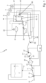
- a water supply and distribution system 1 is generally arranged on-board an aircraft 3 and configured such that it supplies a plurality of consumer assemblies 5 such as sinks and toilets in a lavatory or steam ovens and sinks in a galley, with potable water as will be described in detail below.
- Figure 2 only schematically shows the arrangement of the system 1 in the aircraft 3, and several types of arrangements are conceivable.
- the water supply and distribution system 1 comprises a central water tank 7 which is provided with a connector 9 at its bottom, and the connector 9 being connected to a supply line 11 which is arranged in this exemplary embodiment in such a manner in the aircraft 3 that it includes an angle ⁇ with the horizontal 13 when the aircraft 3 is on the ground and in a horizontal position, and generally the supply line 11 is inclined downwards to a fill/drain coupling 15 which is provided with a valve 17 and which is arranged at the free end of the supply line 11.
- the valve 17 is connected to a control unit 19 of the system 1 and can remotely be controlled such that it can be switched between a closed and an open position.
- the supply line 11 connects the fill/drain coupling 15 with a central pump 21 wherein a filter device 23 is arranged in the supply line 11 between the connection to the central water tank 7 and the central pump 21.
- the central pump 21 is configured as a positive displacement pump and further preferred as a gear pump.
- the filter device 23 improves the quality of water by removing or reducing the concentration of particles such as turbidity or microorganisms or other undesirable substances dissolved in the water.
- the filter device 23 may preferably in the form of a sieve filter. More preferably, the filter device 23 may comprise a combination of several filter stages or filter principles.
- the central pump 21 is also connected to the control unit 19 and can be operated in a supply mode where it conveys water from its upstream side 25 and the supply line 11 to its downstream side 27 that is connected to a high pressure conduit system 29 which will be described in detail below.
- the high pressure conduit system 29 comprises a plurality of conduits 30 connecting the downstream side 27 of the central pump 21 with the consumer assemblies 5. Moreover, the central pump 21 may also be operated in a so-called reverse mode in which it draws water from its downstream side 27 and conveys it to its upstream side 29 and towards the supply line 11.
- the consumer assembly 5 shown in figure 1 is configured as a lavatory with a sink 31 provided with a faucet 33 and a toilet 35 as supply devices.
- a sink 31 provided with a faucet 33 and a toilet 35 as supply devices.
- other forms of consumer assemblies are conceivable such as galleys having sinks etc. and that the present invention is not limited to consumer assemblies in the form of lavatories.
- the buffer tanks of galleys may play a more important role in the method of the present invention, as will become clear below.
- the consumer assembly 5 comprises a buffer tank 37 having an inlet 39 and an outlet 41, the inlet 39 being provided with an inlet valve 42 which is connected to the control unit 19 so that the position of the valve 42 can be controlled by the control unit 19.
- the outlet 41 is connected to the faucet 33 and the toilet 35 via a micro pump 43.
- the line connecting in the outlet 41 with the toilet 35 is also inclined downwards and in this exemplary embodiment includes an angle ⁇ with the horizontal 13, when the aircraft 3 is horizontally arranged on the ground.
- the outlet 41 is arranged at a higher level than the toilet 35. This ensures that when the valve of the toilet 35 is open, the buffer tank 37 may completely be emptied via the toilet 35.
- the buffer tank 37 is provided with a level sensor 44 which is connected to the control unit 19 and configured such that it provides a signal to the control unit 19 indicating the fill level in the buffer tank 37.
- the inlet 39 of the buffer tank 37 is connected to the downstream side of the central pump 21 via the high pressure conduit system 29 including the conduits 30.
- the inlet 39 is arranged at a distance in the vertical direction from the bottom of the buffer tank 37 with the outlet 41.
- This arrangement of the inlet 39 has the effect that when water is drawn out of the buffer tank 37 via the inlet 39 by means of the central pump 21 when being operated in the reverse mode, the buffer tank 37 cannot entirely be emptied and particles which have sedimented at the bottom of the buffer tank 37 are not drawn out of the tank 37 and conveyed towards the pump 21. Instead, these particles can only be removed from the buffer tank 37 via the outlet 41.
- the consumer assemblies 5 comprise not just a sole supply device. Instead, several supply devices are provided and connected with a sole buffer tank 37 which supplies the supply devices with water and there single conduit 30 connecting the consumer assembly 5 with the pump 21 of the system.
- the filter device 23 is provided with a device to monitor the pressure drop between the upstream side and the downstream side of the filter device 23.
- the monitoring device for the pressure drop comprises a first pressure sensor 45 and a second pressure sensor 47, the first sensor 43 being arranged upstream the filter device 23 whereas the second sensor is arranged downstream the filter device 23 at the side pointing towards the central pump 21.
- Each of the sensors 43, 45 are connected to the control unit 19 which is configured such that during operation of the central pump 21 in the supply mode, it collects the signals generated by the sensors 43, 45 so as to generate a further signal representative of the pressure drop across the filter device 23 and, hence, the flow rate across the filter device 23.
- the control unit 19 When this further signal is outside a predetermined range representing a normal condition of the filter device 21 resulting in an acceptable flow rate, the control unit 19 will activate the reverse mode of the central pump 21. However, this activation of the reverse mode may not necessarily take place immediately upon detection that the further signal has left the predetermined range. It is also conceivable that the reverse mode will be activated with a certain delay or when the aircraft 3 has reached a condition where no demand for water in the consumer assemblies 5 can be expected, e.g., when the aircraft is on the ground. However, it is also conceivable that the filter backwash step is performed during flight at time periods in which only small fresh water demands are expected.
- the control unit 19 of the system 1 is configured such that it operates the system 1 and especially the central pump 21 in this exemplary embodiment in the following manner:
- the central pump 21 In a first step during a first time interval the length of which is not fixed, the central pump 21 is constantly or intermittently operated in the supply mode so that water from the central tank 7 is delivered to the consumer assemblies 5 and their buffer tanks 37, which are connected to the downstream side 27 of the pump 21 via the high pressure conduit system 29, so that the buffer tanks 37 of the at least one consumer assembly are filled.
- the inlet valves 42 of those consumer assemblies 5 the buffer tanks 37 of which shall be filled are at the same time or a subsequently brought into its open position.
- the level in the buffer tanks 37 may be monitored by means of the level sensors 44.
- the outlet valve 17 on the fill/drain coupling 15 is kept in the closed position by the control unit 19, and the control unit 19 generates the further signal representative of the flow rate of water through the filter device 21 from the signals of the first and second pressure sensors 45, 47, which signals are representative for the pressure drop across the filter device 21 from which it can be concluded to the respective flow rate.
- the control unit 19 is further configured such that it monitors this further signal and when it is outside the predetermined range representative of an acceptable flow rate through the filter device 21, it is switched, optionally with a delay, to the second step.
- the central pump 21 is operated in the reverse mode by the control unit 19 for a second time interval.
- the central pump 21 draws water from the buffer tanks 37 of the consumer assemblies 5 towards its downstream side 27 and conveys it to its upstream side 25.
- the level sensor 44 of the respective buffer tank 37 indicates that the level in tank is below the level of the inlet 39, the inlet valve 42 of this tank 37 is closed by the control unit 19 and the inlet valve 42 of another tank 37 previously being filled is opened.
- the water is further conveyed through the fill/drain coupling 15 with the valve 17 being brought into the open position by the control unit 19.
- water is conveyed from the buffer tanks 37 to the central water tank 7 with the valve 17 being in the closed position.
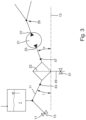
- FIG 3 the section with the filter device 23 of a second embodiment of a water supply and distribution system 1 for an aircraft is shown.
- This embodiment is almost identical to the above-described embodiment and differs only in the configuration and the arrangement of the filter device 23.
- the filter device 23 comprises a filter outlet 49 which connects the upstream side of the filter device 23 where particles etc. are accumulated and the filter cake is formed, with the outside.
- a filter outlet valve 51 is provided which is also connected to the control unit 19 and configured such that it can be switched between an open position and a closed position by the control unit 19.
- first and second pressure sensors 45, 47 are provided on the upstream and the downstream side, respectively of the filter device 23, so that also in this embodiment the flow rate across the filter device 23 may be determined by the control unit 19.
- the filter device 23 is arranged such in the supply line 11, that the sections of the supply line 11 connecting the filter device 23 with the central water tank 7 and the upstream side 25 of the central pump 21 are inclined, so that the filter device 23 is at a lower level than both the upstream side 25 of the central pump 21 and the connector 9 of the central water tank 7.
- both of these sections include an angle ⁇ with the horizontal 13.
- the second embodiment of a water supply and distribution system is operated almost in the same manner as the first embodiment.
- the filter outlet valve 51 is controlled such by the control unit 19 that it is in the open position, so that in the backwash-step water containing the filter cake is expelled via the filter outlet 49 and not guided it to the central water tank or the fill/drain coupling 15.
- the method according to the present invention allows to clean the upstream side of the filter device 23 after relatively short periods of normal use so that the amount of particles which have accumulated in the filter device 23 may be kept at a relatively low level. Hence, only in a minor reduction of the performance of the system 1 occurs between the subsequent cleaning steps applied on the filter device 23.
Landscapes
- Engineering & Computer Science (AREA)
- Aviation & Aerospace Engineering (AREA)
- Water Supply & Treatment (AREA)
- Chemical & Material Sciences (AREA)
- Hydrology & Water Resources (AREA)
- Environmental & Geological Engineering (AREA)
- Life Sciences & Earth Sciences (AREA)
- Organic Chemistry (AREA)
- Nanotechnology (AREA)
- Chemical Kinetics & Catalysis (AREA)
- Manufacturing & Machinery (AREA)
- Transportation (AREA)
- Sanitary Device For Flush Toilet (AREA)
Claims (15)
- Procédé de fonctionnement d'un système d'alimentation et de distribution d'eau embarqué (1) d'un aéronef (3) pour l'alimentation en eau, le système comprenant un réservoir d'eau central (7),une pluralité d'ensembles consommateurs (5), chaque ensemble consommateur (5) comprenant un dispositif d'alimentation et un réservoir tampon (37) et chaque ensemble consommateur (5) étant configuré pour fournir de l'eau à partir du réservoir tampon (37) via le dispositif d'alimentation,une pompe (21) ayant un côté amont (25) et un côté aval (27) et étant configurée de telle sorte qu'elle puisse fonctionner dans un mode d'alimentation et un mode inverse,un dispositif de filtrage (23), etun système de conduits à haute pression (29),dans lequel le réservoir d'eau central (7) est relié au côté amont (25) de la pompe (21) avec le dispositif de filtrage (23) disposé entre le réservoir d'eau central (7) et le côté amont (25),dans lequel le système de conduits haute pression (29) relie le côté aval (27) à la pluralité d'ensembles consommateurs (5), le système de conduits (29) étant configuré de telle sorte que la pompe (21), lorsqu'elle fonctionne en mode d'alimentation, est capable de fournir de l'eau du côté aval (27) au réservoir tampon (37) de chacun des ensembles consommateurs (5),dans lequel, lorsque la pompe (21) fonctionne en mode inverse, elle est capable de transporter l'eau du côté aval (27) vers le côté amont (25),le procédé comprenant les étapes suivantes :faire fonctionner la pompe (21) en mode alimentation de sorte que l'eau du réservoir central (7) soit délivrée à au moins un des groupes consommateurs (5) dans un premier intervalle de temps pendant lequel le réservoir tampon (37) du ou des groupes consommateurs (5) est rempli, etfaire fonctionner la pompe (21) en mode inverse dans un deuxième intervalle de temps de sorte que l'eau provenant du réservoir tampon (37) d'au moins un des ensembles consommateurs (5) passe à travers le dispositif de filtrage (23).
- Procédé selon la revendication 1, dans lequel, pendant l'étape de fonctionnement de la pompe (21) en mode inverse, l'eau est transportée du réservoir tampon (37) d'au moins un des ensembles consommateurs (5) vers le réservoir d'eau central (7).
- Procédé selon la revendication 1, le système comprenant en outre un raccord de remplissage/vidange (15) disposé entre le réservoir d'eau central (7) et le dispositif de filtrage (23), dans lequel, lorsque la pompe (21) fonctionne en mode inverse, l'eau provenant du réservoir tampon (37) d'au moins l'un des ensembles consommateurs (5) passe à travers le raccord de remplissage/vidange (15).
- Procédé selon la revendication 3, le système comprenant en outre une vanne de sortie (17) sur le raccord de remplissage/vidange (15), la vanne de sortie (17) ayant une position fermée et une position ouverte,dans lequel, lorsque la pompe (21) fonctionne en mode alimentation, la vanne de sortie (17) est en position fermée etdans lequel, lorsque la pompe (21) fonctionne en mode inverse, la soupape de sortie (17) est de préférence en position ouverte ou en position fermée.
- Procédé selon l'une quelconque des revendications 1 à 4, dans lequel le réservoir tampon (37) de chacun des au moins un ensemble consommateur (5) comprend une entrée (39) reliée au côté aval de la pompe centrale (21) via le système de conduite haute pression (29) et une sortie (41) reliée au dispositif d'alimentation du au moins un ensemble consommateur (5),dans lequel l'entrée (39) est disposée à une certaine distance dans la direction verticale du fond du réservoir tampon (37), etdans lequel la sortie (41) est disposée dans le fond du réservoir tampon (37).
- Procédé selon l'une quelconque des revendications 1 à 5, dans lequel, lorsque la pompe (21) est actionnée en mode d'alimentation, un signal est généré qui est une mesure du débit d'eau à travers le dispositif de filtrage (23), et dans lequel, lorsque le signal est en dehors d'une plage prédéterminée, la pompe (21) est commutée du mode d'alimentation au mode inverse pour être actionnée en mode inverse pendant le deuxième intervalle de temps.
- Procédé selon la revendication 6, dans lequel la chute de pression entre le côté du dispositif de filtrage (23) connecté au réservoir d'eau central (7) et le côté du dispositif de filtrage (23) connecté au côté amont (25) de la pompe (21) est détectée et dans lequel le signal est généré sur la base de la chute de pression détectée.
- Système d'alimentation et de distribution d'eau embarqué (1) d'un aéronef (3) pour fournir de l'eau, le système comprenantun réservoir d'eau central (7),une pluralité d'ensembles consommateurs (5), chaque ensemble consommateur (5) comprenant un dispositif d'alimentation et un réservoir tampon (37) et chaque ensemble consommateur (5) étant configuré pour fournir de l'eau à partir du réservoir tampon (37) via le dispositif d'alimentation,une pompe ayant un côté amont et un côté aval et étant configurée de telle sorte qu'elle puisse fonctionner dans un mode d'alimentation et un mode inverse,un dispositif de filtrage (23),un système de conduits haute pression (29), etune unité de commande (19),dans lequel le réservoir d'eau central (7) est relié au côté amont de la pompe, le dispositif de filtrage (23) étant disposé entre le réservoir d'eau central (7) et le côté amont,dans lequel le système de conduit (30) relie le côté aval (27) à la pluralité d'ensembles consommateurs (5), le système de conduit (30) étant configuré de telle sorte que la pompe (21), lorsqu'elle fonctionne en mode d'alimentation, est capable de fournir de l'eau du côté aval (27) au réservoir tampon (37) de chacun des ensembles consommateurs (5),dans lequel, lorsque la pompe fonctionne en mode inverse, elle est capable de transporter l'eau du côté aval (27) vers le côté amont (25),l'unité de commande (19) étant connectée à la pompe et étant configurée de telle sorte qu'ellefait fonctionner la pompe (21) en mode d'alimentation dans un premier intervalle de temps de sorte que l'eau du réservoir central (7) soit délivrée à au moins un des ensembles consommateurs (5) dans lequel le réservoir tampon (37) de l'au moins un ensemble consommateur (5) est rempli, etfait fonctionner la pompe (21) en mode inverse dans un deuxième intervalle de temps différent du premier intervalle de temps de sorte que l'eau provenant du réservoir tampon (37) d'au moins un des ensembles consommateurs (5) passe à travers le dispositif de filtrage (23).
- Système selon la revendication 8, dans lequel le système est en outre configuré de telle sorte que lorsque la pompe (21) fonctionne en mode inverse, l'eau est transportée du réservoir tampon (37) d'au moins un des ensembles consommateurs (5) vers le réservoir d'eau central (7).
- Système selon la revendication 8 comprenant en outre un raccord de remplissage/vidange (15) disposé entre le réservoir d'eau central (7) et le dispositif de filtrage (23), le système étant en outre configuré de telle sorte que, lorsque la pompe (21) fonctionne en mode inverse, l'eau provenant du réservoir tampon (37) d'au moins l'un des ensembles consommateurs (5) passe à travers le raccord de remplissage/vidange (15).
- Système selon la revendication 10, comprenant en outre une vanne de sortie (17) sur le raccord de remplissage/vidange (15), la vanne de sortie (17) ayant une position fermée et une position ouverte et étant connectée de manière fonctionnelle à l'unité de commande (19).dans lequel l'unité de commande (19) est en outre configurée de telle sorte que lorsque la pompe (21) fonctionne en mode alimentation, la vanne de sortie (17) est en position fermée, etlorsque la pompe (21) fonctionne en mode inverse, la vanne de sortie (17) est de préférence en position ouverte.
- Système selon l'une quelconque des revendications 8 à 11, le réservoir tampon (37) de chacun des au moins un ensemble consommateur (5) comprenant une entrée (39) reliée au côté aval de la pompe centrale (21) via le système de conduite haute pression (29) et une sortie (41) reliée au dispositif d'alimentation du au moins un ensemble consommateur (5),dans lequel l'entrée (39) est disposée à une certaine distance dans la direction verticale du fond du réservoir tampon (37), etdans lequel la sortie (41) est disposée dans le fond du réservoir tampon (37).
- Système selon l'une quelconque des revendications 8 à 12, comprenant un dispositif de détection connecté à l'unité de commande (19) et configuré pour générer un signal qui est une mesure du débit d'eau à travers le dispositif de filtrage (23), et dans lequel l'unité de commande (19) est configurée de sorte que lorsque le signal est en dehors d'une plage prédéterminée, la pompe (21) est commutée du mode d'alimentation au mode inverse pour fonctionner en mode inverse pendant le deuxième intervalle de temps.
- Système selon la revendication 13, dans lequel le dispositif de détection est configuré pour détecter la chute de pression entre le côté du dispositif de filtrage (23) connecté au réservoir d'eau central (7) et le côté du dispositif connecté au côté amont (25) de la pompe (21) et dans lequel le dispositif de détection est en outre configuré de telle sorte que le signal est généré sur la base de la chute de pression détectée.
- Aéronef (3) comprenant un système selon l'une quelconque des revendications 8 à 14.
Priority Applications (3)
| Application Number | Priority Date | Filing Date | Title |
|---|---|---|---|
| EP22192704.9A EP4331990B1 (fr) | 2022-08-29 | 2022-08-29 | Système d'alimentation et de distribution d'eau à bord d'un aéronef et procédé de fonctionnement d'un tel système avec un faible effort de maintenance |
| CN202311078047.5A CN117622491A (zh) | 2022-08-29 | 2023-08-24 | 飞行器上的供水和分配系统以及操作这样的系统的方法 |
| US18/238,053 US12534387B2 (en) | 2022-08-29 | 2023-08-25 | Water supply and distribution system on-board an aircraft and method for operating such system with low maintenance effort |
Applications Claiming Priority (1)
| Application Number | Priority Date | Filing Date | Title |
|---|---|---|---|
| EP22192704.9A EP4331990B1 (fr) | 2022-08-29 | 2022-08-29 | Système d'alimentation et de distribution d'eau à bord d'un aéronef et procédé de fonctionnement d'un tel système avec un faible effort de maintenance |
Publications (2)
| Publication Number | Publication Date |
|---|---|
| EP4331990A1 EP4331990A1 (fr) | 2024-03-06 |
| EP4331990B1 true EP4331990B1 (fr) | 2025-06-18 |
Family
ID=83151896
Family Applications (1)
| Application Number | Title | Priority Date | Filing Date |
|---|---|---|---|
| EP22192704.9A Active EP4331990B1 (fr) | 2022-08-29 | 2022-08-29 | Système d'alimentation et de distribution d'eau à bord d'un aéronef et procédé de fonctionnement d'un tel système avec un faible effort de maintenance |
Country Status (3)
| Country | Link |
|---|---|
| US (1) | US12534387B2 (fr) |
| EP (1) | EP4331990B1 (fr) |
| CN (1) | CN117622491A (fr) |
Families Citing this family (1)
| Publication number | Priority date | Publication date | Assignee | Title |
|---|---|---|---|---|
| EP4635848A1 (fr) * | 2024-04-16 | 2025-10-22 | AIRBUS Operations GmbH | Système d'alimentation et de distribution d'eau à utilisation optimisée d'eau embarquée |
Family Cites Families (12)
| Publication number | Priority date | Publication date | Assignee | Title |
|---|---|---|---|---|
| US5303739A (en) * | 1991-09-30 | 1994-04-19 | Deutsche Aerospace Airbus Gmbh | Fresh water supply system for an aircraft |
| DE4202719C2 (de) * | 1992-01-31 | 1993-11-04 | Deutsche Aerospace Airbus | Wassersystem fuer ein flugzeug |
| WO2003084882A1 (fr) | 2002-04-04 | 2003-10-16 | Millipore Corporation | Filtre a eau composite |
| US20060169645A1 (en) * | 2005-01-31 | 2006-08-03 | Hsueh Angela M | Water treatment systems and techniques principally for use on-board aircraft |
| DE102009013554B4 (de) * | 2009-03-17 | 2016-03-03 | Airbus Operations Gmbh | Luftfahrzeug mit einer Rezirkulationsdusche und zugehöriges Verfahren zur Wasseraufbereitung |
| US20120111432A1 (en) * | 2010-11-10 | 2012-05-10 | Goodrich Corporation | Aircraft potable water system |
| US9273449B2 (en) | 2012-10-04 | 2016-03-01 | B/E Aerospace, Inc. | Aircraft galley water distribution manifold |
| EP2878352B1 (fr) * | 2013-11-29 | 2018-03-28 | Donaldson Company, Inc. | Ensemble de filtre à carburant et procédé permettant de purger l'eau d'un ensemble de filtre à carburant |
| EP3164314B1 (fr) * | 2014-09-30 | 2020-03-25 | Siemens Mobility GmbH | Toilettes à fonction de lavage à contre-courant pour un filtre à particules |
| ES2728758T3 (es) | 2017-04-05 | 2019-10-28 | Henkel Ag & Co Kgaa | Composiciones de detergente que comprenden mananasas bacterianas |
| EP3385163B1 (fr) * | 2017-04-07 | 2024-03-27 | Airbus Operations GmbH | Aéronef comprenant un système d'alimentation et de distribution d'eau à haute pression |
| DE102018208602A1 (de) | 2018-05-30 | 2019-12-05 | Airbus Operations Gmbh | Verfahren zur Desinfektion eines Wassersystems eines Luftfahrzeugs |
-
2022
- 2022-08-29 EP EP22192704.9A patent/EP4331990B1/fr active Active
-
2023
- 2023-08-24 CN CN202311078047.5A patent/CN117622491A/zh active Pending
- 2023-08-25 US US18/238,053 patent/US12534387B2/en active Active
Also Published As
| Publication number | Publication date |
|---|---|
| CN117622491A (zh) | 2024-03-01 |
| US20240083770A1 (en) | 2024-03-14 |
| EP4331990A1 (fr) | 2024-03-06 |
| US12534387B2 (en) | 2026-01-27 |
Similar Documents
| Publication | Publication Date | Title |
|---|---|---|
| US10036153B2 (en) | Toilet device having a backflushing function for a particle filter | |
| CA2789121C (fr) | Systeme de recipient d'eau de rincage pour l'eau de rincage d'une toilette mobile | |
| KR101479791B1 (ko) | 진공 하수 시스템 | |
| EP2703358A1 (fr) | Dispositif de recyclage des eaux grises dans un véhicule de transport | |
| US5932091A (en) | Oily waste water treatment system | |
| EP3860943B1 (fr) | Agencement de stockage et d'alimentation de carburant avec un ensemble de conditionnement et de filtration de carburant | |
| US12534387B2 (en) | Water supply and distribution system on-board an aircraft and method for operating such system with low maintenance effort | |
| KR102212754B1 (ko) | 이물질 여과기능의 관로형 필터시스템 | |
| GB2236960A (en) | Water drainage system | |
| US20110042311A1 (en) | Membrane system | |
| RU200513U1 (ru) | Рельсовое транспортное средство с отсасывающим трубопроводом | |
| EP3746605B1 (fr) | Système de recyclage d'eau | |
| WO2024079447A1 (fr) | Système de recyclage d'eau | |
| US20130180908A1 (en) | Filter Backflush System for Entrained Filtration Elements | |
| KR100937907B1 (ko) | 단수 방지를 위한 무인관리형 정수장치 | |
| RU2481984C2 (ru) | Система санитарно-гигиенического оборудования транспортного средства | |
| EP4516673A1 (fr) | Toilettes réutilisant des eaux grises pour rincer des toilettes | |
| NL1005789C2 (nl) | Inrichting en werkwijze voor het filteren van water. | |
| CN113648898B (zh) | 一种液体冲洗搅拌系统和方法以及储油罐 | |
| WO2020089575A1 (fr) | Appareil de rinçage |
Legal Events
| Date | Code | Title | Description |
|---|---|---|---|
| PUAI | Public reference made under article 153(3) epc to a published international application that has entered the european phase |
Free format text: ORIGINAL CODE: 0009012 |
|
| STAA | Information on the status of an ep patent application or granted ep patent |
Free format text: STATUS: THE APPLICATION HAS BEEN PUBLISHED |
|
| AK | Designated contracting states |
Kind code of ref document: A1 Designated state(s): AL AT BE BG CH CY CZ DE DK EE ES FI FR GB GR HR HU IE IS IT LI LT LU LV MC MK MT NL NO PL PT RO RS SE SI SK SM TR |
|
| STAA | Information on the status of an ep patent application or granted ep patent |
Free format text: STATUS: REQUEST FOR EXAMINATION WAS MADE |
|
| 17P | Request for examination filed |
Effective date: 20240906 |
|
| RBV | Designated contracting states (corrected) |
Designated state(s): AL AT BE BG CH CY CZ DE DK EE ES FI FR GB GR HR HU IE IS IT LI LT LU LV MC MK MT NL NO PL PT RO RS SE SI SK SM TR |
|
| GRAP | Despatch of communication of intention to grant a patent |
Free format text: ORIGINAL CODE: EPIDOSNIGR1 |
|
| STAA | Information on the status of an ep patent application or granted ep patent |
Free format text: STATUS: GRANT OF PATENT IS INTENDED |
|
| INTG | Intention to grant announced |
Effective date: 20250128 |
|
| GRAS | Grant fee paid |
Free format text: ORIGINAL CODE: EPIDOSNIGR3 |
|
| GRAA | (expected) grant |
Free format text: ORIGINAL CODE: 0009210 |
|
| STAA | Information on the status of an ep patent application or granted ep patent |
Free format text: STATUS: THE PATENT HAS BEEN GRANTED |
|
| AK | Designated contracting states |
Kind code of ref document: B1 Designated state(s): AL AT BE BG CH CY CZ DE DK EE ES FI FR GB GR HR HU IE IS IT LI LT LU LV MC MK MT NL NO PL PT RO RS SE SI SK SM TR |
|
| REG | Reference to a national code |
Ref country code: GB Ref legal event code: FG4D |
|
| REG | Reference to a national code |
Ref country code: CH Ref legal event code: EP |
|
| REG | Reference to a national code |
Ref country code: DE Ref legal event code: R096 Ref document number: 602022016010 Country of ref document: DE |
|
| REG | Reference to a national code |
Ref country code: CH Ref legal event code: EP |
|
| REG | Reference to a national code |
Ref country code: IE Ref legal event code: FG4D |
|
| PG25 | Lapsed in a contracting state [announced via postgrant information from national office to epo] |
Ref country code: FI Free format text: LAPSE BECAUSE OF FAILURE TO SUBMIT A TRANSLATION OF THE DESCRIPTION OR TO PAY THE FEE WITHIN THE PRESCRIBED TIME-LIMIT Effective date: 20250618 |
|
| PGFP | Annual fee paid to national office [announced via postgrant information from national office to epo] |
Ref country code: DE Payment date: 20250820 Year of fee payment: 4 |
|
| REG | Reference to a national code |
Ref country code: LT Ref legal event code: MG9D |
|
| PG25 | Lapsed in a contracting state [announced via postgrant information from national office to epo] |
Ref country code: NO Free format text: LAPSE BECAUSE OF FAILURE TO SUBMIT A TRANSLATION OF THE DESCRIPTION OR TO PAY THE FEE WITHIN THE PRESCRIBED TIME-LIMIT Effective date: 20250918 Ref country code: GR Free format text: LAPSE BECAUSE OF FAILURE TO SUBMIT A TRANSLATION OF THE DESCRIPTION OR TO PAY THE FEE WITHIN THE PRESCRIBED TIME-LIMIT Effective date: 20250919 |
|
| PG25 | Lapsed in a contracting state [announced via postgrant information from national office to epo] |
Ref country code: BG Free format text: LAPSE BECAUSE OF FAILURE TO SUBMIT A TRANSLATION OF THE DESCRIPTION OR TO PAY THE FEE WITHIN THE PRESCRIBED TIME-LIMIT Effective date: 20250618 |
|
| PG25 | Lapsed in a contracting state [announced via postgrant information from national office to epo] |
Ref country code: HR Free format text: LAPSE BECAUSE OF FAILURE TO SUBMIT A TRANSLATION OF THE DESCRIPTION OR TO PAY THE FEE WITHIN THE PRESCRIBED TIME-LIMIT Effective date: 20250618 |
|
| PGFP | Annual fee paid to national office [announced via postgrant information from national office to epo] |
Ref country code: FR Payment date: 20250828 Year of fee payment: 4 Ref country code: AT Payment date: 20251020 Year of fee payment: 4 |
|
| PG25 | Lapsed in a contracting state [announced via postgrant information from national office to epo] |
Ref country code: RS Free format text: LAPSE BECAUSE OF FAILURE TO SUBMIT A TRANSLATION OF THE DESCRIPTION OR TO PAY THE FEE WITHIN THE PRESCRIBED TIME-LIMIT Effective date: 20250918 |
|
| REG | Reference to a national code |
Ref country code: NL Ref legal event code: MP Effective date: 20250618 |
|
| PG25 | Lapsed in a contracting state [announced via postgrant information from national office to epo] |
Ref country code: LV Free format text: LAPSE BECAUSE OF FAILURE TO SUBMIT A TRANSLATION OF THE DESCRIPTION OR TO PAY THE FEE WITHIN THE PRESCRIBED TIME-LIMIT Effective date: 20250618 |
|
| PG25 | Lapsed in a contracting state [announced via postgrant information from national office to epo] |
Ref country code: NL Free format text: LAPSE BECAUSE OF FAILURE TO SUBMIT A TRANSLATION OF THE DESCRIPTION OR TO PAY THE FEE WITHIN THE PRESCRIBED TIME-LIMIT Effective date: 20250618 |
|
| PG25 | Lapsed in a contracting state [announced via postgrant information from national office to epo] |
Ref country code: PT Free format text: LAPSE BECAUSE OF FAILURE TO SUBMIT A TRANSLATION OF THE DESCRIPTION OR TO PAY THE FEE WITHIN THE PRESCRIBED TIME-LIMIT Effective date: 20251020 |
|
| REG | Reference to a national code |
Ref country code: AT Ref legal event code: MK05 Ref document number: 1803990 Country of ref document: AT Kind code of ref document: T Effective date: 20250618 |
|
| PG25 | Lapsed in a contracting state [announced via postgrant information from national office to epo] |
Ref country code: IS Free format text: LAPSE BECAUSE OF FAILURE TO SUBMIT A TRANSLATION OF THE DESCRIPTION OR TO PAY THE FEE WITHIN THE PRESCRIBED TIME-LIMIT Effective date: 20251018 |
|
| PG25 | Lapsed in a contracting state [announced via postgrant information from national office to epo] |
Ref country code: AT Free format text: LAPSE BECAUSE OF FAILURE TO SUBMIT A TRANSLATION OF THE DESCRIPTION OR TO PAY THE FEE WITHIN THE PRESCRIBED TIME-LIMIT Effective date: 20250618 Ref country code: SM Free format text: LAPSE BECAUSE OF FAILURE TO SUBMIT A TRANSLATION OF THE DESCRIPTION OR TO PAY THE FEE WITHIN THE PRESCRIBED TIME-LIMIT Effective date: 20250618 |
|
| PG25 | Lapsed in a contracting state [announced via postgrant information from national office to epo] |
Ref country code: CZ Free format text: LAPSE BECAUSE OF FAILURE TO SUBMIT A TRANSLATION OF THE DESCRIPTION OR TO PAY THE FEE WITHIN THE PRESCRIBED TIME-LIMIT Effective date: 20250618 |
|
| PG25 | Lapsed in a contracting state [announced via postgrant information from national office to epo] |
Ref country code: PL Free format text: LAPSE BECAUSE OF FAILURE TO SUBMIT A TRANSLATION OF THE DESCRIPTION OR TO PAY THE FEE WITHIN THE PRESCRIBED TIME-LIMIT Effective date: 20250618 |
|
| PG25 | Lapsed in a contracting state [announced via postgrant information from national office to epo] |
Ref country code: EE Free format text: LAPSE BECAUSE OF FAILURE TO SUBMIT A TRANSLATION OF THE DESCRIPTION OR TO PAY THE FEE WITHIN THE PRESCRIBED TIME-LIMIT Effective date: 20250618 |
|
| PG25 | Lapsed in a contracting state [announced via postgrant information from national office to epo] |
Ref country code: SK Free format text: LAPSE BECAUSE OF FAILURE TO SUBMIT A TRANSLATION OF THE DESCRIPTION OR TO PAY THE FEE WITHIN THE PRESCRIBED TIME-LIMIT Effective date: 20250618 |
|
| PG25 | Lapsed in a contracting state [announced via postgrant information from national office to epo] |
Ref country code: ES Free format text: LAPSE BECAUSE OF FAILURE TO SUBMIT A TRANSLATION OF THE DESCRIPTION OR TO PAY THE FEE WITHIN THE PRESCRIBED TIME-LIMIT Effective date: 20250618 |