EP4330131B1 - Tragflügel mit variablem auftrieb und variablem widerstand für ein wasserfahrzeug - Google Patents
Tragflügel mit variablem auftrieb und variablem widerstand für ein wasserfahrzeug Download PDFInfo
- Publication number
- EP4330131B1 EP4330131B1 EP22724729.3A EP22724729A EP4330131B1 EP 4330131 B1 EP4330131 B1 EP 4330131B1 EP 22724729 A EP22724729 A EP 22724729A EP 4330131 B1 EP4330131 B1 EP 4330131B1
- Authority
- EP
- European Patent Office
- Prior art keywords
- hydrofoil
- fuselage
- wings
- wing
- mobile assembly
- Prior art date
- Legal status (The legal status is an assumption and is not a legal conclusion. Google has not performed a legal analysis and makes no representation as to the accuracy of the status listed.)
- Active
Links
Images

Classifications
-
- B—PERFORMING OPERATIONS; TRANSPORTING
- B63—SHIPS OR OTHER WATERBORNE VESSELS; RELATED EQUIPMENT
- B63B—SHIPS OR OTHER WATERBORNE VESSELS; EQUIPMENT FOR SHIPPING
- B63B1/00—Hydrodynamic or hydrostatic features of hulls or of hydrofoils
- B63B1/16—Hydrodynamic or hydrostatic features of hulls or of hydrofoils deriving additional lift from hydrodynamic forces
- B63B1/24—Hydrodynamic or hydrostatic features of hulls or of hydrofoils deriving additional lift from hydrodynamic forces of hydrofoil type
- B63B1/242—Mounting, suspension of the foils
-
- B—PERFORMING OPERATIONS; TRANSPORTING
- B63—SHIPS OR OTHER WATERBORNE VESSELS; RELATED EQUIPMENT
- B63B—SHIPS OR OTHER WATERBORNE VESSELS; EQUIPMENT FOR SHIPPING
- B63B1/00—Hydrodynamic or hydrostatic features of hulls or of hydrofoils
- B63B1/16—Hydrodynamic or hydrostatic features of hulls or of hydrofoils deriving additional lift from hydrodynamic forces
- B63B1/24—Hydrodynamic or hydrostatic features of hulls or of hydrofoils deriving additional lift from hydrodynamic forces of hydrofoil type
- B63B1/28—Hydrodynamic or hydrostatic features of hulls or of hydrofoils deriving additional lift from hydrodynamic forces of hydrofoil type with movable hydrofoils
-
- B—PERFORMING OPERATIONS; TRANSPORTING
- B63—SHIPS OR OTHER WATERBORNE VESSELS; RELATED EQUIPMENT
- B63B—SHIPS OR OTHER WATERBORNE VESSELS; EQUIPMENT FOR SHIPPING
- B63B1/00—Hydrodynamic or hydrostatic features of hulls or of hydrofoils
- B63B1/16—Hydrodynamic or hydrostatic features of hulls or of hydrofoils deriving additional lift from hydrodynamic forces
- B63B1/24—Hydrodynamic or hydrostatic features of hulls or of hydrofoils deriving additional lift from hydrodynamic forces of hydrofoil type
- B63B1/28—Hydrodynamic or hydrostatic features of hulls or of hydrofoils deriving additional lift from hydrodynamic forces of hydrofoil type with movable hydrofoils
- B63B1/283—Hydrodynamic or hydrostatic features of hulls or of hydrofoils deriving additional lift from hydrodynamic forces of hydrofoil type with movable hydrofoils movable around a vertical axis, e.g. for steering
-
- B—PERFORMING OPERATIONS; TRANSPORTING
- B63—SHIPS OR OTHER WATERBORNE VESSELS; RELATED EQUIPMENT
- B63B—SHIPS OR OTHER WATERBORNE VESSELS; EQUIPMENT FOR SHIPPING
- B63B1/00—Hydrodynamic or hydrostatic features of hulls or of hydrofoils
- B63B1/16—Hydrodynamic or hydrostatic features of hulls or of hydrofoils deriving additional lift from hydrodynamic forces
- B63B1/24—Hydrodynamic or hydrostatic features of hulls or of hydrofoils deriving additional lift from hydrodynamic forces of hydrofoil type
- B63B1/28—Hydrodynamic or hydrostatic features of hulls or of hydrofoils deriving additional lift from hydrodynamic forces of hydrofoil type with movable hydrofoils
- B63B1/285—Hydrodynamic or hydrostatic features of hulls or of hydrofoils deriving additional lift from hydrodynamic forces of hydrofoil type with movable hydrofoils changing the angle of attack or the lift of the foil
- B63B1/286—Hydrodynamic or hydrostatic features of hulls or of hydrofoils deriving additional lift from hydrodynamic forces of hydrofoil type with movable hydrofoils changing the angle of attack or the lift of the foil using flaps
-
- B—PERFORMING OPERATIONS; TRANSPORTING
- B63—SHIPS OR OTHER WATERBORNE VESSELS; RELATED EQUIPMENT
- B63B—SHIPS OR OTHER WATERBORNE VESSELS; EQUIPMENT FOR SHIPPING
- B63B32/00—Water sports boards; Accessories therefor
- B63B32/60—Board appendages, e.g. fins, hydrofoils or centre boards
- B63B32/64—Adjustable, e.g. by adding sections, by removing sections or by changing orientation or profile
-
- B—PERFORMING OPERATIONS; TRANSPORTING
- B63—SHIPS OR OTHER WATERBORNE VESSELS; RELATED EQUIPMENT
- B63B—SHIPS OR OTHER WATERBORNE VESSELS; EQUIPMENT FOR SHIPPING
- B63B32/00—Water sports boards; Accessories therefor
- B63B32/60—Board appendages, e.g. fins, hydrofoils or centre boards
- B63B32/66—Arrangements for fixation to the board, e.g. fin boxes or foil boxes
-
- B—PERFORMING OPERATIONS; TRANSPORTING
- B63—SHIPS OR OTHER WATERBORNE VESSELS; RELATED EQUIPMENT
- B63B—SHIPS OR OTHER WATERBORNE VESSELS; EQUIPMENT FOR SHIPPING
- B63B1/00—Hydrodynamic or hydrostatic features of hulls or of hydrofoils
- B63B1/16—Hydrodynamic or hydrostatic features of hulls or of hydrofoils deriving additional lift from hydrodynamic forces
- B63B1/24—Hydrodynamic or hydrostatic features of hulls or of hydrofoils deriving additional lift from hydrodynamic forces of hydrofoil type
- B63B1/26—Hydrodynamic or hydrostatic features of hulls or of hydrofoils deriving additional lift from hydrodynamic forces of hydrofoil type having more than one hydrofoil
-
- B—PERFORMING OPERATIONS; TRANSPORTING
- B63—SHIPS OR OTHER WATERBORNE VESSELS; RELATED EQUIPMENT
- B63B—SHIPS OR OTHER WATERBORNE VESSELS; EQUIPMENT FOR SHIPPING
- B63B1/00—Hydrodynamic or hydrostatic features of hulls or of hydrofoils
- B63B1/16—Hydrodynamic or hydrostatic features of hulls or of hydrofoils deriving additional lift from hydrodynamic forces
- B63B1/24—Hydrodynamic or hydrostatic features of hulls or of hydrofoils deriving additional lift from hydrodynamic forces of hydrofoil type
- B63B1/28—Hydrodynamic or hydrostatic features of hulls or of hydrofoils deriving additional lift from hydrodynamic forces of hydrofoil type with movable hydrofoils
- B63B1/30—Hydrodynamic or hydrostatic features of hulls or of hydrofoils deriving additional lift from hydrodynamic forces of hydrofoil type with movable hydrofoils retracting or folding
-
- Y—GENERAL TAGGING OF NEW TECHNOLOGICAL DEVELOPMENTS; GENERAL TAGGING OF CROSS-SECTIONAL TECHNOLOGIES SPANNING OVER SEVERAL SECTIONS OF THE IPC; TECHNICAL SUBJECTS COVERED BY FORMER USPC CROSS-REFERENCE ART COLLECTIONS [XRACs] AND DIGESTS
- Y02—TECHNOLOGIES OR APPLICATIONS FOR MITIGATION OR ADAPTATION AGAINST CLIMATE CHANGE
- Y02T—CLIMATE CHANGE MITIGATION TECHNOLOGIES RELATED TO TRANSPORTATION
- Y02T70/00—Maritime or waterways transport
- Y02T70/10—Measures concerning design or construction of watercraft hulls
Definitions
- the invention relates to a hydrofoil for a watercraft and to a watercraft comprising such a hydrofoil.
- Watercraft such as boats, sailboards, stand-up paddleboards, surfboards, kitesurfing boards, or windsurfing boards use hydrofoils (or foils) to reduce the drag of a watercraft hull moving through the water and provide faster travel.
- hydrofoils or foils
- Hydrofoils such as the one in the document FR3049262 allow the height of the hull of the nautical craft to be varied depending on the speed of the craft in the water.
- Hydrofoils consist of a fuselage, a mast to be attached to the watercraft, two wings at the front of the fuselage, and a tailplane at the rear of the fuselage.
- the wings are intended to provide hydrodynamic lift to the hydrofoil when it is moving through the water.
- prior art hydrofoils have the disadvantage of causing drag in the water, reducing the speed of the watercraft when it reaches high speeds. The performance of watercraft is therefore limited by prior art hydrofoils.
- the aim of the invention is therefore to overcome the drawbacks of the prior art by proposing a hydrofoil making it possible to reduce the lift and therefore the drag of the hydrofoil in the water depending on the speed of the nautical craft in order to increase the speed of the craft.
- the invention thus relates, in its broadest sense, to a hydrofoil for a watercraft comprising a fuselage and two wings arranged on each side of the fuselage and intended to provide hydrodynamic lift to the hydrofoil when it is moving in the water.
- the two wings are rotatable relative to the fuselage between a deployed position when the hydrofoil is stationary and a retracted position towards a rear portion of the fuselage by the pressure of the water exerted on the wings when the hydrofoil moves in the water.
- the invention thus provides a hydrofoil making it possible to reduce the lift and therefore the drag of the hydrofoil in the water as a function of the speed of the watercraft and more precisely when the speed of the watercraft increases.
- variable geometry wings of the hydrofoil reduce drag at the leading edges and therefore the friction of the hydrofoil with the water.
- the machine nautical can thus reach higher speeds. Navigation comfort is also improved.
- the two wings are substantially perpendicular to a longitudinal axis L of the fuselage.
- each of the two wings forms an angle with the longitudinal axis L when the speed of the hydrofoil is greater than a minimum speed. This angle is less than 90° and gradually decreases when the speed of the hydrofoil increases.
- the hydrofoil comprises a mobile assembly moving in translation inside the fuselage along the longitudinal axis (L) and relative to the fuselage, the wings being mechanically connected to said mobile assembly, the retraction of the two wings towards the fuselage causing the translation of the mobile assembly towards a front part of the fuselage, and the deployment of the two wings causing the translation of the mobile assembly towards the rear part of the fuselage.
- This mobile set provides a simple and sturdy means of movement.
- the wings comprise a first wing rotatably mounted on the fuselage about a first axis and a second wing rotatably mounted on the fuselage about a second axis.
- the hydrofoil comprises connecting means connecting the wings to the movable assembly.
- the connecting means comprise two recesses hollowed out on each side of the movable assembly, including a first recess receiving an inner end of the first wing and a second recess receiving an inner end of the second wing.
- the inner end of the first wing forms a lever against a front portion of the first recess to push the movable assembly toward the front portion of the fuselage when the speed of the hydrofoil increases.
- the inner end of the second wing forms a lever against a front portion of the second recess to push the movable assembly toward the front portion of the fuselage when the speed of the hydrofoil increases.
- the hydrofoil comprises compression means connected to the moving assembly and opposing a resistance force to a force exerted by the pressure of the water on the wings during the movement of the hydrofoil so that the retraction of the wings is adapted to the speed of the hydrofoil.
- the compression means oppose a resistance force to a force exerted by the pressure of the water on the wings so that the folding of the wings is adapted to the speed of the craft in order to obtain the best lift/drag/speed ratio.
- the compression means comprise at least one spring mounted in compression between a front end of the fuselage and a front end of the mobile assembly.
- the mobile assembly has an elongated shape along the longitudinal axis L.
- the hydrofoil comprises a tail unit fixed to a rear end of the mobile assembly so that the tail unit is movable in translation between a deployed position when the wings are deployed and a position retracted towards the fuselage when the wings are retracted.
- the empennage may or may not fit partially inside the fuselage.
- the overall length of the hydrofoil can be decreased by a translational movement in order to bring the tail closer to the wings in a linear manner, in correlation, in synergy and simultaneously with the progressive orientation of the wings towards the rear. This allows to further reduce lift and drag in the water.
- the movable assembly comprises a first movable element actuated by water pressure on the first wing and a second movable element actuated by water pressure on the second wing.
- the first movable element and the second movable element move independently of each other depending on the trajectory followed by the hydrofoil.
- each of the wings is autonomous in the event of a change in the hydrofoil's trajectory. This allows the management of the speed differential in turns. The performance of the hydrofoil is improved.
- the invention also relates to a nautical craft comprising at least one hydrofoil as defined above.
- the hydrofoil is attached to the nautical craft by a mast.
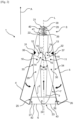
- FIG.1 illustrates a hydrofoil 1 (or foil) comprising a fuselage 2, a mast 3 intended to be fixed to a nautical craft and two wings 4, 5 including a first wing 4 and a second wing 5 positioned at a front part 8 of the fuselage 2.
- front and rear are defined relative to the normal direction of advancement A of the hydrofoil 1 in the water.
- the fuselage 2 extends along a longitudinal axis L.
- the mast 3 is perpendicular to the fuselage 2.
- the hydrofoil 1 can also comprise a tail unit 6 positioned at a rear part 7 of the fuselage 2.
- the tail unit 6 can be formed of a single fin or of two fins 42, 43 substantially parallel to the two wings 4, 5.
- the wings 4, 5 and the empennage 6 are intended to provide hydrodynamic lift to the hydrofoil 1 when it is moving in the water in the direction of advancement A.
- Wings 4, 5 are approximately perpendicular to mast 3.
- the empennage 6 may comprise a fin substantially perpendicular to the fins 42, 43.
- the wings 4, 5 may form an angle with the mast 3 which is different from 90°. This angle may be between 89° and 80° or between 91° and 100°, for example.
- the watercraft can be a boat, a windsurf board, a stand up paddle board, a surfboard, a kite surfboard, a wingsurf board or a windsurf board, for example.
- the two wings 4, 5 fold towards the fuselage 2 by the pressure of the water exerted on the wings 4, 5 when the hydrofoil 1 moves in the water in the direction of advancement A, preferably at very high speed.
- the two wings 4, 5 are rotatable relative to the fuselage 2 between a deployed position and a position retracted towards a rear portion 7 of the fuselage 2.
- the deployed position corresponds to a substantially perpendicular positioning of the two wings 4, 5 relative to the longitudinal axis L, as illustrated in the [ Fig.1 ], when the speed of hydrofoil 1 is zero or low.
- the two wings 4, 5 are preferably perpendicular to the longitudinal axis L of the fuselage 2.
- An angle ⁇ 1 of approximately 90° is formed between the first wing 4 and the longitudinal axis L of the fuselage 2.
- an angle ⁇ 2 of approximately 90° is formed between the second wing 5 and the longitudinal axis L of the fuselage 2.
- the two wings 4, 5 are aligned.
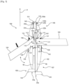
- both wings 4, 5 are in the retracted position towards the rear part 7 of the fuselage 2, as illustrated in the [ Fig.2 ], that is, when the speed of hydrofoil 1 is greater than a minimum speed, the angles ⁇ 1 and ⁇ 2 are less than 90° and gradually decrease as the speed of hydrofoil 1 increases.
- Each of the two wings 4, 5 extends in a main direction P. More precisely, the angle ⁇ 1 or ⁇ 2 corresponds to the angle between the longitudinal axis L of the fuselage 2 and the main direction P of each of the two wings 4, 5.
- angles ⁇ 1 and ⁇ 2 are equal.
- the two wings 4, 5 may not be completely perpendicular to the longitudinal axis L of the fuselage 2 and may form an angle ⁇ 1 or ⁇ 2 slightly less than 90°, 85° for example, with the longitudinal axis L, when the craft nautical is at a standstill.
- the water pressure on the wings 4, 5 causes them to fold towards the rear part 7 of the fuselage 2, forming swept wings whose degree of sweep varies according to the speed.
- the wings 4, 5 are mechanically connected to a mobile assembly 9, 9a, 9b moving in translation inside the fuselage 2 along the longitudinal axis L and relative to the fuselage 2 and the wings 4, 5.
- the retraction of the two wings 4, 5 towards the fuselage 2 causes the translation of the mobile assembly 9, 9a, 9b towards the front part 8 of the fuselage 2.
- the deployment of the two wings 4, 5 causes the translation of the mobile assembly 9, 9a, 9b towards the rear part 7 of the fuselage 2.
- the mobile assembly 9, 9a, 9b extends along the longitudinal axis L.
- the mobile assembly 9, 9a, 9b comprises a single mobile element 9, having a rod shape.
- the hydrofoil 1 comprises connecting means 12, 13 connecting the wings 4, 5 to the movable element 9 so as to allow simultaneous movement of the two wings 4, 5 and to obtain angles ⁇ 1 and ⁇ 2 which are substantially identical for the two wings.
- the connecting means 12, 13 comprise two recesses 14, 15 hollowed out on each side of the movable element 9, including a first recess 14 receiving an internal end 16 of the first wing 4 and a second recess 15 receiving an internal end 17 of the second wing 5.
- the inner end 16 of the first wing 4 forms a lever against a front portion 18 of the first recess 14 to push the movable element 9 toward the front portion 8 of the fuselage 2 when the speed of the hydrofoil 1 increases.
- the inner end 17 of the second wing 5 also forms a lever against a front portion 19 of the second recess 15 to push the movable element 9 toward the front portion 8 of the fuselage 2 when the speed of the hydrofoil 1 increases.
- the inner end 16 of the first wing 4 and the inner end 17 of the second wing 5 form a point or have a rounded shape with a small radius of curvature.
- the first wing 4 is rotatably mounted on the fuselage 2 about a first axis 10 and the second wing 5 is rotatably mounted on the fuselage 2 about a second axis 11.
- the first axis 10 and the second axis 11 are positioned near the respective inner ends 16, 17.
- the connecting means 12, 13 may comprise two sets of gears (not shown) including a first set of gears associated with the first wing 4 and a second set of gears associated with the second wing 5.
- Each gear set comprises a first gear fixed to the inner end 16 of the first wing 4 cooperating with a second gear fixed to one of the sides of the movable element 9.
- the gears have curved or half-sphere shapes.
- the first gear has a counter shape of the second gear.
- the first gear has a concave shape and the second gear has a convex shape.
- the hydrofoil 1 comprises compression means 20, 20a, 20b connected to the movable element 9 and opposing a resistance force to a force exerted by the pressure of the water on the wings 4, 5 during the movement of the hydrofoil 1 so that the retraction of the wings 4, 5 is adapted to the speed of the hydrofoil 1.
- the compression means 20, 20a, 20b are placed at the front of the fuselage.
- the compression means 20, 20a, 20b comprise at least one spring 20, 20a, 20b mounted in compression between a front end 21 of the fuselage 2 and a front end 22 of the movable element 9.
- the compression means 20, 20a, 20b are calibrated according to the desired performances.
- the compression means 20, 20a, 20b comprise a single spring 20.
- the spring 20 tends to push the movable element 9 towards the rear part 7 of the fuselage 2.
- the retraction of the wings 4, 5 occurs from a minimum speed of the hydrofoil 1 (or threshold).
- the water pressure on the wings 4, 5 must be sufficient to allow the spring 20 to be compressed.
- the minimum speed can be one knot, for example.
- angles ⁇ 1 and ⁇ 2 depend on the calibration of the spring 20 or its stiffness coefficient.
- the front end 21 of the fuselage 2 comprises a first lug 38 in which a first end 40 of the spring 20 is inserted.
- a second lug 39 is provided at the front end 22 of the movable element 9 for the insertion and holding of a second end 41 of the spring 20.
- the compression means 20, 20a, 20b can be replaced by a return means such as a return spring connected to the front end 22 of the movable element 9 and to the rear part 7 of the fuselage 2.
- the compression means 20, 20a, 20b may be a hydraulic, pneumatic or gas (nitrogen) cylinder, for example.
- the compression means 20, 20a, 20b can be positioned in mast 3.
- the empennage 6 is fixed in a non-removable manner to the rear part 7 of the fuselage 2.
- the empennage 6 is fixed to a rear end 23 of the movable element 9 so that the empennage 6 is movable in translation between a deployed position when the wings 4, 5 are deployed and a retracted position towards the fuselage 2 when the wings 4, 5 are retracted.
- the empennage 6 follows the translational movement of the mobile assembly 9 along the longitudinal axis L.
- the total length of the hydrofoil 1 can decrease by a translational movement in order to bring the fins 42 of the empennage 6 closer to the wings 4, 5, in a linear manner, in correlation, in synergy and simultaneously with the progressive orientation of the wings 4, 5 towards the rear.
- the empennage may or may not fit partially inside the fuselage.
- the rear portion 7 of the fuselage 2 comprises a slot into which a central portion 24 of the empennage 6 is inserted when the empennage 6 is in the retracted position.
- the leading edges are further reduced.
- the empennage 6 moves but does not fit into the rear part 7 of the fuselage 2.
- a lateral end edge 25 of the first wing 4 is opposite an edge 27 of a first fin 42 of the empennage 6.
- a lateral end edge 26 of the second wing 5 is opposite an edge 28 of a second fin 43 of the empennage 6.
- the fuselage 2 comprises a first lateral slot 29 extending along the longitudinal axis L to allow the passage of a portion 33 of the first wing 4 and its retraction inside the fuselage 2 when the first wing 4 is in the retracted position.
- the fuselage 2 comprises a second lateral slot 30 extending along the longitudinal axis L to allow the passage of a portion 34 of the second wing 5 and its retraction inside the fuselage 2 when the second wing 5 is in the retracted position.
- the first side slot 29 includes a stop 31 at a front end 36 of the first side slit 29.
- the second side slot 30 includes a stop 32 at a front end 37 of the second side slot 30.
- the lateral slots 29, 30 are each delimited by a fairing 44, 45 projecting from the external surface of the fuselage 2, towards the outside, and covering a part of the wings 4, 5 to ensure aerodynamic continuity between the fuselage 2 and the wings 4, 5.
- the mobile assembly 9, 9a, 9b comprises a first mobile element 9a actuated by a first wing 104 and a second mobile element 9b actuated by a second wing 105.
- the first wing 104 is rotatably mounted on the fuselage 102 about a first axis 110 and the second wing 105 is rotatably mounted on the fuselage 102 about a second axis 111.
- the first movable element 9a and the second movable element 9b are distinct and move independently of each other.
- First connecting means 112 mechanically connect the first wing 104 to the first movable element 9a and second connecting means 113 mechanically connect the second wing 105 to the second movable element 9b.
- the connecting means 112, 113 comprise two recesses 114, 115 hollowed out on each side of the movable elements 9a, 9b, including a first recess 114 receiving an internal end 116 of the first wing 104 and a second recess 115 receiving an internal end 117 of the second wing 105.
- the inner end 116 of the first wing 104 forms a lever against a front portion 118 of the first recess 114 to push the first movable element 9a toward the front portion 108 of the fuselage 102 when the speed of the hydrofoil 100 increases.
- the inner end 117 of the second wing 105 also forms a lever against a front portion 119 of the second recess 115 to push the second movable element 9b toward the front portion 108 of the fuselage 102 when the speed of the hydrofoil 100 increases.
- the hydrofoil 100 comprises a first compression means 20a connected to the first movable element 9a and opposing a resistance force to a force exerted by the pressure of the water on the first wing 104 during the movement of the hydrofoil 100 so that the retraction of the first wing 104 is adapted to the speed of the hydrofoil 100 and to the trajectory followed by the nautical craft.
- the hydrofoil 100 also comprises a second compression means 20b connected to the second movable element 9b and opposing a resistance force to a force exerted by the pressure of the water on the second wing 105 during the movement of the hydrofoil 100 so that the retraction of the second wing 105 is adapted to the speed of the hydrofoil 100 and the trajectory taken by the nautical vehicle.
- the compression means 20a, 20b are placed at the front of the fuselage 2.
- the first compression means 20a comprises a first spring 20a mounted in compression between a front end 121 of the fuselage 102 and a front end 22a of the first movable element 9a.
- the second compression means 20b comprises a second spring 20b mounted in compression between a front end 121 of the fuselage 102 and a front end 22b of the second movable element 9b.
- Springs 20a, 20b are calibrated according to requirements and in particular the desired lift/drag/speed ratio.
- the springs 20a, 20b are calibrated identically and are identical.
- the springs 20a, 20b tend to independently push each of the movable elements 9a, 9b towards the rear part 107 of the fuselage 102.
- the retraction of the wings 104, 105 occurs from a minimum speed of the hydrofoil 100 (or threshold).
- the water pressure on the wings 104, 105 must be sufficient to allow the springs 20a, 20b to be compressed.
- the two wings 104, 105 are preferably perpendicular to the longitudinal axis L of the fuselage 102.
- An angle ⁇ 1 of approximately 90° is formed between the first wing 104 and the longitudinal axis L of the fuselage 102.
- an angle ⁇ 2 of approximately 90° is formed between the second wing 105 and the longitudinal axis L of the fuselage 102.
- the two wings 104, 105 are aligned.
- the water pressure on the wings 104, 105 causes compression of the springs 20a, 20b and consequently retraction of the wings 104, 105 towards the rear portion 107 of the fuselage 102.
- the water pressure on the first wing 104 is greater than the water pressure on the second wing 105.
- the first spring 20a is more compressed than the second spring 20b.
- the first wing 104 is more retracted than the second wing 105.
- the angle ⁇ 1 is therefore smaller than the angle ⁇ 2 .
- the lift and therefore the drag in the water are greater for the first wing 104 than for the second wing 105.
- angles ⁇ 1 and ⁇ 2 are therefore not always identical and depend on the direction of the hydrofoil 100 and the radius of curvature of the turn.
- each of the wings 104, 105 is autonomous in the event of a variation in the trajectory of the hydrofoil 100. This allows management of the speed differential in turns.
- angles ⁇ 1 and ⁇ 2 and therefore the level of lift and drag also depend on the calibration of the springs 20a, 20b.
- the front end 121 of the fuselage 102 comprises a first lug 138 into which a first end 140 of the first spring 20a is inserted.
- the front end 121 of the fuselage 102 comprises a second lug 138a into which a first end 140a of the second spring 20b is inserted.
- the empennage 106 is fixed in a non-removable manner to the rear portion 107 of the fuselage 102.
- the empennage 106 comprises two fins 142, 143 substantially parallel to the two wings 104, 105.
- a first fin 142 is attached to a rear end 23a of the first movable element 9a such that the first fin 142 is movable in translation between a deployed position when the first wing 104 is unfolded and a retracted position inside the fuselage 2 when the first wing 104 is retracted.
- a second fin 143 is attached to a rear end 23b of the second movable element 9b such that the second fin 143 is movable in translation between a deployed position when the second wing 105 is unfolded and a retracted position inside the fuselage 102 when the second wing 105 is folded.
- the fins 142, 143 are independent and follow the translational movement of the respective mobile assemblies 9a, 9b along the longitudinal axis L.
- the fuselage 102 comprises a first lateral slot 129 extending along the longitudinal axis L to allow the passage of a portion 133 of the first wing 104 and its retraction inside the fuselage 102 when the first wing 104 is in the retracted position.
- the fuselage 102 comprises a second lateral slot 130 extending along the longitudinal axis L to allow the passage of a portion 134 of the second wing 105 and its retraction inside the fuselage 102 when the second wing 105 is in the retracted position.
- the first side slot 129 includes a stop 131 at a front end 136 of the first side slot 129.
- the second side slot 130 includes a stop 132 at a front end 137 of the second side slot 130.
- the lateral slots 129, 130 are each delimited by a fairing 144, 145 projecting from the external surface of the fuselage 102, towards the exterior, and covering a portion of the wings 104, 105 to provide aerodynamic continuity between the fuselage 102 and the wings 104, 105.
Landscapes
- Physics & Mathematics (AREA)
- Fluid Mechanics (AREA)
- Chemical & Material Sciences (AREA)
- Engineering & Computer Science (AREA)
- Combustion & Propulsion (AREA)
- Mechanical Engineering (AREA)
- Ocean & Marine Engineering (AREA)
- Hydraulic Turbines (AREA)
- Other Liquid Machine Or Engine Such As Wave Power Use (AREA)
- Harvesting Machines For Specific Crops (AREA)
- Valve Device For Special Equipments (AREA)
Claims (8)
- Tragflügelboot (1, 100) für ein Wasserfahrzeug, bestehend aus einem Rumpf (2, 102) und zwei Flügeln (4, 5, 104, 105), die auf jeder Seite des Rumpfs (2, 102) angeordnet sind und für einen hydrodynamischen Auftrieb sorgen sollen Tragflügelboot (1, 100), wenn es sich im Wasser bewegt, dadurch gekennzeichnet, dass die beiden Flügel (4, 5, 104, 105) relativ zum Rumpf (2, 102) zwischen einer ausgeklappten Position, wenn das Tragflügelboot ( 1, 100) stationär ist und sich durch den Druck des auf die Flügel (4, 5, 104, 105) ausgeübten Wassers in Richtung eines hinteren Teils (7) des Rumpfs (2, 102) zurückzieht, wenn das Tragflügelboot (1, 100) sich im Wasser bewegt, stehen in der ausgefahrenen Stellung die beiden Flügel (4, 5, 104, 105) im Wesentlichen senkrecht zu einer Längsachse (L) des Rumpfes (2, 102), in der eingefahrenen Stellung jeweils wobei die beiden Flügel (4, 5, 104, 105) mit der Längsachse (L) einen Winkel bilden, wenn die Geschwindigkeit des Tragflügels (1, 100) größer als ein Geschwindigkeitsminimum ist, wobei der Winkel kleiner als 90° ist und allmählich abnimmt wenn die Geschwindigkeit des Tragflügels (1, 100) zunimmt, werden die Flügel (4, 5, 104, 105) mechanisch mit einer beweglichen Baugruppe (9, 9a, 9b) verbunden, die sich translatorisch innerhalb des Rumpfes (2, 102) entlang bewegt der Längsachse (L) und relativ zum Rumpf (2, 102), wobei das Zurückziehen der beiden Flügel (4, 5, 104, 105) in Richtung Rumpf (2, 102) die Translation der beweglichen Einheit (9, 9a, 9b) in Richtung eines vorderen Teils (8, 108) des Rumpfes (2, 102) und das Ausfahren der beiden Flügel (4, 5, 104, 105) bewirkt die Translation der beweglichen Baugruppe (9, 9a, 9b) in Richtung des hinteren Teils (7, 107) des Rumpfes (2, 102).
- Tragflügelboot (1, 100) nach Anspruch 1, dadurch gekennzeichnet, dass die Flügel (4, 5, 104, 105) einen ersten Flügel (4, 104) umfassen, der drehbar am Rumpf (2, 102) um eine erste Achse montiert ist ( 10, 110) und einen zweiten Flügel (5, 105), der drehbar am Rumpf (2, 102) um eine zweite Achse (11, 111) montiert ist, wobei das Tragflügelboot (1, 100) Mittel zur Verbindung (12, 13, 112) aufweist , 113) die Flügel (4, 5, 104, 105) mit der mobilen Baugruppe (9, 9a, 9b) verbindet.
- Tragflügelboot (1, 100) nach Anspruch 2, dadurch gekennzeichnet, dass die Verbindungsmittel (12, 13, 112, 113) zwei Aussparungen (14, 15, 114, 115) umfassen, die auf jeder Seite der mobilen Baugruppe (9, 9a) gegraben sind , 9b) einschließlich einer ersten Aussparung (14, 114), die ein inneres Ende (16, 116) des ersten Flügels (4, 104) aufnimmt, und einer zweiten Aussparung (15, 115), die ein inneres Ende (17, 117) des ersten Flügels aufnimmt zweiten Flügel (5, 105), wobei das innere Ende (16, 116) des ersten Flügels (4, 104) einen Hebel gegen einen vorderen Teil (18, 118) der ersten Aussparung (14, 114) bildet, um das bewegliche zu drücken Baugruppe (9, 9a, 9b) in Richtung des vorderen Teils (8, 108) des Rumpfs (2, 102), wenn die Geschwindigkeit des Tragflügels (1, 100) zunimmt, und des inneren Endes (17, 117) des zweiten Flügels (5, 105), die einen Hebel gegen einen vorderen Teil (19, 119) der zweiten Aussparung (15, 115) bilden, um die bewegliche Baugruppe (9, 9a, 9b) in Richtung des vorderen Teils (8, 108) des Rumpfes zu drücken (2, 102), wenn die Geschwindigkeit des Tragflügelboots (1, 100) zunimmt.
- Tragflügelboot (1, 100) nach einem der Ansprüche 1 bis 3, dadurch gekennzeichnet, dass es Kompressionsmittel (20, 20a, 20b) umfasst, die mit der mobilen Einheit (9, 9a, 9b) verbunden sind und einer Widerstandskraft entgegenwirken Kraft, die durch den Druck des Wassers auf die Flügel (4, 5, 104, 105) während der Bewegung des Tragflügelboots (1, 100) ausgeübt wird, so dass das Einfahren der Flügel (4, 5, 104, 105) angepasst wird die Geschwindigkeit des Tragflügelboots (1, 100).
- Tragflügelboot (1, 100) nach Anspruch 4, dadurch gekennzeichnet, dass die Kompressionsmittel (20, 20a, 20b) mindestens eine Feder (20, 20a, 20b) umfassen, die unter Druck zwischen einem vorderen Ende (21, 121) des Tragflügelboots montiert ist Rumpf (2, 102) und ein vorderes Ende (22, 22a, 22b) der mobilen Baugruppe (9, 9a, 9b).
- Tragflügelboot (1, 100) nach einem der Ansprüche 1 bis 5, dadurch gekennzeichnet, dass die bewegliche Baugruppe (9, 9a, 9b) eine längliche Form entlang der Längsachse (L) aufweist, wobei das Tragflügelboot ein Leitwerk (6, 106) umfasst ) an einem hinteren Ende (23, 23a, 23b) der beweglichen Baugruppe (9, 9a, 9b) befestigt, so dass das Höhenleitwerk (6, 106) translatorisch zwischen einer Position bewegbar ist, in der die Flügel (4, 5, 104) ausgefahren sind , 105) ausgefahren sind und eine zurückgezogene Position zum Rumpf (2, 102) einnehmen, wenn die Flügel (4, 5, 104, 105) eingefahren sind.
- Tragflügelboot (1, 100) nach einem der Ansprüche 1 bis 6, dadurch gekennzeichnet, dass die bewegliche Baugruppe (9, 9a, 9b) ein erstes bewegliches Element (9a) umfasst, das durch den Druck des Wassers auf den ersten Flügel (104) betätigt wird ) und ein zweites bewegliches Element (9b), das durch Wasserdruck auf den zweiten Flügel (105) betätigt wird, wobei sich das erste bewegliche Element (9a) und das zweite bewegliche Element (9b) unabhängig voneinander relativ zueinander bewegen, abhängig von der Flugbahn, der sie folgen Tragflügelboot (100).
- Wasserfahrzeug, dadurch gekennzeichnet, dass es mindestens ein Tragflügelboot (1, 100) nach einem der Ansprüche 1 bis 7 umfasst, wobei das Tragflügelboot (1, 100) durch einen Mast (3) an dem Wasserfahrzeug befestigt ist.
Applications Claiming Priority (2)
| Application Number | Priority Date | Filing Date | Title |
|---|---|---|---|
| FR2104390A FR3122402B1 (fr) | 2021-04-28 | 2021-04-28 | Hydrofoil à portance et traînée variables pour un engin nautique |
| PCT/EP2022/060705 WO2022229020A1 (fr) | 2021-04-28 | 2022-04-22 | Hydrofoil à portance et traînée variables pour un engin nautique |
Publications (2)
| Publication Number | Publication Date |
|---|---|
| EP4330131A1 EP4330131A1 (de) | 2024-03-06 |
| EP4330131B1 true EP4330131B1 (de) | 2024-08-21 |
Family
ID=77180099
Family Applications (1)
| Application Number | Title | Priority Date | Filing Date |
|---|---|---|---|
| EP22724729.3A Active EP4330131B1 (de) | 2021-04-28 | 2022-04-22 | Tragflügel mit variablem auftrieb und variablem widerstand für ein wasserfahrzeug |
Country Status (6)
| Country | Link |
|---|---|
| US (1) | US12084148B2 (de) |
| EP (1) | EP4330131B1 (de) |
| AU (1) | AU2022265203A1 (de) |
| CA (1) | CA3216092A1 (de) |
| FR (1) | FR3122402B1 (de) |
| WO (1) | WO2022229020A1 (de) |
Families Citing this family (1)
| Publication number | Priority date | Publication date | Assignee | Title |
|---|---|---|---|---|
| CN118810987B (zh) * | 2024-07-29 | 2025-01-10 | 广东海洋大学 | 与水下滑翔机水翼相适配的安装组件及安装方法 |
Family Cites Families (13)
| Publication number | Priority date | Publication date | Assignee | Title |
|---|---|---|---|---|
| US2444332A (en) * | 1944-12-07 | 1948-06-29 | Briggs Earl | Wing folding arrangement for submersible aircraft |
| US3090978A (en) * | 1962-09-07 | 1963-05-28 | William H Hanson | Water ski device |
| US3195495A (en) * | 1963-03-13 | 1965-07-20 | Thurston Erlandsen Corp | Hydrofoil boat |
| US3802369A (en) * | 1971-04-22 | 1974-04-09 | K Ishimoto | Sporting boats |
| US4077077A (en) * | 1977-01-13 | 1978-03-07 | Harper Alex M | Stabilizer keel |
| US4752262A (en) * | 1987-04-03 | 1988-06-21 | Martinmaas Werner W | Laterally unstable small water craft with stabilizing wings |
| US5404830A (en) * | 1992-05-11 | 1995-04-11 | Ligozio; Peter A. | Finned boat hull |
| NL1019207C2 (nl) * | 2001-10-22 | 2003-04-23 | Argonautic | Pleziervaartuig. |
| US6886481B1 (en) * | 2004-03-03 | 2005-05-03 | Douglas W. Lord | Pivotable bulb mounted foil for sailboats |
| FR3049262B1 (fr) | 2016-03-23 | 2019-07-12 | Olivier Paul Michel Moulin | Hydrofoil a aile mediane et ses reglages |
| ITUA20163845A1 (it) * | 2016-05-26 | 2017-11-26 | Giulia Caponnetto | Sistema alare e tavola idroplana |
| US11130549B2 (en) * | 2016-08-17 | 2021-09-28 | Dombois Designs, Inc. | Self-propelling hydrofoil device |
| CN110065609A (zh) * | 2019-05-20 | 2019-07-30 | 中国船舶科学研究中心(中国船舶重工集团公司第七0二研究所) | 一种深海载人潜水器同步折叠式水平稳定翼 |
-
2021
- 2021-04-28 FR FR2104390A patent/FR3122402B1/fr active Active
-
2022
- 2022-04-22 CA CA3216092A patent/CA3216092A1/fr active Pending
- 2022-04-22 US US18/557,203 patent/US12084148B2/en active Active
- 2022-04-22 WO PCT/EP2022/060705 patent/WO2022229020A1/fr not_active Ceased
- 2022-04-22 AU AU2022265203A patent/AU2022265203A1/en not_active Abandoned
- 2022-04-22 EP EP22724729.3A patent/EP4330131B1/de active Active
Also Published As
| Publication number | Publication date |
|---|---|
| US20240217623A1 (en) | 2024-07-04 |
| US12084148B2 (en) | 2024-09-10 |
| EP4330131A1 (de) | 2024-03-06 |
| WO2022229020A1 (fr) | 2022-11-03 |
| AU2022265203A1 (en) | 2023-12-14 |
| FR3122402B1 (fr) | 2025-02-14 |
| FR3122402A1 (fr) | 2022-11-04 |
| CA3216092A1 (fr) | 2022-11-03 |
Similar Documents
| Publication | Publication Date | Title |
|---|---|---|
| EP2668098B1 (de) | Motorflugzeug mit gemischter hydrodynamischer und aerodynamischer struktur zum starten und landen auf wasser, boden oder schnee | |
| EP0511050B1 (de) | Einrichtung mit mindestens einem aerodynamischen Formteil mit veränderlicher Geometrie, die ein Grenzschicht-Kontrollsystem beinhaltet | |
| WO2016034814A1 (fr) | Aile portante escamotable | |
| FR2581961A1 (fr) | Aile propulsive | |
| EP3157808B1 (de) | Flügel für den antrieb eines fahrzeuges | |
| FR2937302A1 (fr) | Avion a empennage queue-de-morue. | |
| EP4330131B1 (de) | Tragflügel mit variablem auftrieb und variablem widerstand für ein wasserfahrzeug | |
| EP3687890A1 (de) | Motorboot mit durch kippen einziehbaren tragflügeln | |
| WO2006134267A1 (fr) | Engin multimilieux | |
| CA2714815C (fr) | Dispositif anticouple d'un giravion | |
| EP3209551B1 (de) | Takelage zur vereinfachung von halse-/wendemanövern | |
| CA2534404C (fr) | Aile rigide de portance variable par deploiement d'une aile souple | |
| FR3029497A1 (fr) | Bateau a voile a appendice de stabilisation ameliore | |
| EP3778376A1 (de) | Autonomer kite-antrieb | |
| FR2461642A1 (fr) | Le greement-planeur | |
| FR2598756A1 (fr) | Dispositif de derive ou analogue, agissant dans un fluide | |
| FR2833238A1 (fr) | Bateau multicoques de type hydroptere a foils repliables | |
| EP4440921A1 (de) | System aus gelenkigen flügeln für ein boot | |
| FR2623159A1 (fr) | Plan anti-derive asymetrique pivotant pour multicoques | |
| FR2563800A1 (fr) | Objet muni d'ailes de portance hydrodynamique | |
| WO2019064105A1 (fr) | Bateau moteur à foils rétractables présentant une configuration dissymétrique en position passive | |
| FR2612150A1 (fr) | Embarcation a voile a ailes partiellement immergees | |
| FR2830233A1 (fr) | Coque pour structure navigante | |
| FR2932772A1 (fr) | Embarcation multicoques rotatives. | |
| FR2600725A1 (fr) | Voilure portante. |
Legal Events
| Date | Code | Title | Description |
|---|---|---|---|
| STAA | Information on the status of an ep patent application or granted ep patent |
Free format text: STATUS: UNKNOWN |
|
| STAA | Information on the status of an ep patent application or granted ep patent |
Free format text: STATUS: THE INTERNATIONAL PUBLICATION HAS BEEN MADE |
|
| PUAI | Public reference made under article 153(3) epc to a published international application that has entered the european phase |
Free format text: ORIGINAL CODE: 0009012 |
|
| STAA | Information on the status of an ep patent application or granted ep patent |
Free format text: STATUS: REQUEST FOR EXAMINATION WAS MADE |
|
| 17P | Request for examination filed |
Effective date: 20231116 |
|
| AK | Designated contracting states |
Kind code of ref document: A1 Designated state(s): AL AT BE BG CH CY CZ DE DK EE ES FI FR GB GR HR HU IE IS IT LI LT LU LV MC MK MT NL NO PL PT RO RS SE SI SK SM TR |
|
| GRAP | Despatch of communication of intention to grant a patent |
Free format text: ORIGINAL CODE: EPIDOSNIGR1 |
|
| STAA | Information on the status of an ep patent application or granted ep patent |
Free format text: STATUS: GRANT OF PATENT IS INTENDED |
|
| INTG | Intention to grant announced |
Effective date: 20240322 |
|
| GRAS | Grant fee paid |
Free format text: ORIGINAL CODE: EPIDOSNIGR3 |
|
| GRAA | (expected) grant |
Free format text: ORIGINAL CODE: 0009210 |
|
| STAA | Information on the status of an ep patent application or granted ep patent |
Free format text: STATUS: THE PATENT HAS BEEN GRANTED |
|
| DAV | Request for validation of the european patent (deleted) | ||
| DAX | Request for extension of the european patent (deleted) | ||
| AK | Designated contracting states |
Kind code of ref document: B1 Designated state(s): AL AT BE BG CH CY CZ DE DK EE ES FI FR GB GR HR HU IE IS IT LI LT LU LV MC MK MT NL NO PL PT RO RS SE SI SK SM TR |
|
| REG | Reference to a national code |
Ref country code: GB Ref legal event code: FG4D Free format text: NOT ENGLISH |
|
| REG | Reference to a national code |
Ref country code: CH Ref legal event code: EP |
|
| REG | Reference to a national code |
Ref country code: IE Ref legal event code: FG4D Free format text: LANGUAGE OF EP DOCUMENT: FRENCH |
|
| REG | Reference to a national code |
Ref country code: DE Ref legal event code: R096 Ref document number: 602022005522 Country of ref document: DE |
|
| REG | Reference to a national code |
Ref country code: LT Ref legal event code: MG9D |
|
| REG | Reference to a national code |
Ref country code: NL Ref legal event code: MP Effective date: 20240821 |
|
| PG25 | Lapsed in a contracting state [announced via postgrant information from national office to epo] |
Ref country code: NO Free format text: LAPSE BECAUSE OF FAILURE TO SUBMIT A TRANSLATION OF THE DESCRIPTION OR TO PAY THE FEE WITHIN THE PRESCRIBED TIME-LIMIT Effective date: 20241121 |
|
| REG | Reference to a national code |
Ref country code: AT Ref legal event code: MK05 Ref document number: 1715266 Country of ref document: AT Kind code of ref document: T Effective date: 20240821 |
|
| PG25 | Lapsed in a contracting state [announced via postgrant information from national office to epo] |
Ref country code: GR Free format text: LAPSE BECAUSE OF FAILURE TO SUBMIT A TRANSLATION OF THE DESCRIPTION OR TO PAY THE FEE WITHIN THE PRESCRIBED TIME-LIMIT Effective date: 20241122 Ref country code: PL Free format text: LAPSE BECAUSE OF FAILURE TO SUBMIT A TRANSLATION OF THE DESCRIPTION OR TO PAY THE FEE WITHIN THE PRESCRIBED TIME-LIMIT Effective date: 20240821 Ref country code: NL Free format text: LAPSE BECAUSE OF FAILURE TO SUBMIT A TRANSLATION OF THE DESCRIPTION OR TO PAY THE FEE WITHIN THE PRESCRIBED TIME-LIMIT Effective date: 20240821 Ref country code: FI Free format text: LAPSE BECAUSE OF FAILURE TO SUBMIT A TRANSLATION OF THE DESCRIPTION OR TO PAY THE FEE WITHIN THE PRESCRIBED TIME-LIMIT Effective date: 20240821 Ref country code: PT Free format text: LAPSE BECAUSE OF FAILURE TO SUBMIT A TRANSLATION OF THE DESCRIPTION OR TO PAY THE FEE WITHIN THE PRESCRIBED TIME-LIMIT Effective date: 20241223 |
|
| PG25 | Lapsed in a contracting state [announced via postgrant information from national office to epo] |
Ref country code: BG Free format text: LAPSE BECAUSE OF FAILURE TO SUBMIT A TRANSLATION OF THE DESCRIPTION OR TO PAY THE FEE WITHIN THE PRESCRIBED TIME-LIMIT Effective date: 20240821 |
|
| PG25 | Lapsed in a contracting state [announced via postgrant information from national office to epo] |
Ref country code: LV Free format text: LAPSE BECAUSE OF FAILURE TO SUBMIT A TRANSLATION OF THE DESCRIPTION OR TO PAY THE FEE WITHIN THE PRESCRIBED TIME-LIMIT Effective date: 20240821 |
|
| PG25 | Lapsed in a contracting state [announced via postgrant information from national office to epo] |
Ref country code: AT Free format text: LAPSE BECAUSE OF FAILURE TO SUBMIT A TRANSLATION OF THE DESCRIPTION OR TO PAY THE FEE WITHIN THE PRESCRIBED TIME-LIMIT Effective date: 20240821 Ref country code: IS Free format text: LAPSE BECAUSE OF FAILURE TO SUBMIT A TRANSLATION OF THE DESCRIPTION OR TO PAY THE FEE WITHIN THE PRESCRIBED TIME-LIMIT Effective date: 20241221 |
|
| PG25 | Lapsed in a contracting state [announced via postgrant information from national office to epo] |
Ref country code: HR Free format text: LAPSE BECAUSE OF FAILURE TO SUBMIT A TRANSLATION OF THE DESCRIPTION OR TO PAY THE FEE WITHIN THE PRESCRIBED TIME-LIMIT Effective date: 20240821 |
|
| PG25 | Lapsed in a contracting state [announced via postgrant information from national office to epo] |
Ref country code: RS Free format text: LAPSE BECAUSE OF FAILURE TO SUBMIT A TRANSLATION OF THE DESCRIPTION OR TO PAY THE FEE WITHIN THE PRESCRIBED TIME-LIMIT Effective date: 20241121 Ref country code: ES Free format text: LAPSE BECAUSE OF FAILURE TO SUBMIT A TRANSLATION OF THE DESCRIPTION OR TO PAY THE FEE WITHIN THE PRESCRIBED TIME-LIMIT Effective date: 20240821 |
|
| PG25 | Lapsed in a contracting state [announced via postgrant information from national office to epo] |
Ref country code: RS Free format text: LAPSE BECAUSE OF FAILURE TO SUBMIT A TRANSLATION OF THE DESCRIPTION OR TO PAY THE FEE WITHIN THE PRESCRIBED TIME-LIMIT Effective date: 20241121 Ref country code: PT Free format text: LAPSE BECAUSE OF FAILURE TO SUBMIT A TRANSLATION OF THE DESCRIPTION OR TO PAY THE FEE WITHIN THE PRESCRIBED TIME-LIMIT Effective date: 20241223 Ref country code: PL Free format text: LAPSE BECAUSE OF FAILURE TO SUBMIT A TRANSLATION OF THE DESCRIPTION OR TO PAY THE FEE WITHIN THE PRESCRIBED TIME-LIMIT Effective date: 20240821 Ref country code: NO Free format text: LAPSE BECAUSE OF FAILURE TO SUBMIT A TRANSLATION OF THE DESCRIPTION OR TO PAY THE FEE WITHIN THE PRESCRIBED TIME-LIMIT Effective date: 20241121 Ref country code: NL Free format text: LAPSE BECAUSE OF FAILURE TO SUBMIT A TRANSLATION OF THE DESCRIPTION OR TO PAY THE FEE WITHIN THE PRESCRIBED TIME-LIMIT Effective date: 20240821 Ref country code: LV Free format text: LAPSE BECAUSE OF FAILURE TO SUBMIT A TRANSLATION OF THE DESCRIPTION OR TO PAY THE FEE WITHIN THE PRESCRIBED TIME-LIMIT Effective date: 20240821 Ref country code: IS Free format text: LAPSE BECAUSE OF FAILURE TO SUBMIT A TRANSLATION OF THE DESCRIPTION OR TO PAY THE FEE WITHIN THE PRESCRIBED TIME-LIMIT Effective date: 20241221 Ref country code: HR Free format text: LAPSE BECAUSE OF FAILURE TO SUBMIT A TRANSLATION OF THE DESCRIPTION OR TO PAY THE FEE WITHIN THE PRESCRIBED TIME-LIMIT Effective date: 20240821 Ref country code: GR Free format text: LAPSE BECAUSE OF FAILURE TO SUBMIT A TRANSLATION OF THE DESCRIPTION OR TO PAY THE FEE WITHIN THE PRESCRIBED TIME-LIMIT Effective date: 20241122 Ref country code: FI Free format text: LAPSE BECAUSE OF FAILURE TO SUBMIT A TRANSLATION OF THE DESCRIPTION OR TO PAY THE FEE WITHIN THE PRESCRIBED TIME-LIMIT Effective date: 20240821 Ref country code: ES Free format text: LAPSE BECAUSE OF FAILURE TO SUBMIT A TRANSLATION OF THE DESCRIPTION OR TO PAY THE FEE WITHIN THE PRESCRIBED TIME-LIMIT Effective date: 20240821 Ref country code: BG Free format text: LAPSE BECAUSE OF FAILURE TO SUBMIT A TRANSLATION OF THE DESCRIPTION OR TO PAY THE FEE WITHIN THE PRESCRIBED TIME-LIMIT Effective date: 20240821 Ref country code: AT Free format text: LAPSE BECAUSE OF FAILURE TO SUBMIT A TRANSLATION OF THE DESCRIPTION OR TO PAY THE FEE WITHIN THE PRESCRIBED TIME-LIMIT Effective date: 20240821 |
|
| PG25 | Lapsed in a contracting state [announced via postgrant information from national office to epo] |
Ref country code: RO Free format text: LAPSE BECAUSE OF FAILURE TO SUBMIT A TRANSLATION OF THE DESCRIPTION OR TO PAY THE FEE WITHIN THE PRESCRIBED TIME-LIMIT Effective date: 20240821 Ref country code: SM Free format text: LAPSE BECAUSE OF FAILURE TO SUBMIT A TRANSLATION OF THE DESCRIPTION OR TO PAY THE FEE WITHIN THE PRESCRIBED TIME-LIMIT Effective date: 20240821 Ref country code: DK Free format text: LAPSE BECAUSE OF FAILURE TO SUBMIT A TRANSLATION OF THE DESCRIPTION OR TO PAY THE FEE WITHIN THE PRESCRIBED TIME-LIMIT Effective date: 20240821 |
|
| PG25 | Lapsed in a contracting state [announced via postgrant information from national office to epo] |
Ref country code: EE Free format text: LAPSE BECAUSE OF FAILURE TO SUBMIT A TRANSLATION OF THE DESCRIPTION OR TO PAY THE FEE WITHIN THE PRESCRIBED TIME-LIMIT Effective date: 20240821 |
|
| PG25 | Lapsed in a contracting state [announced via postgrant information from national office to epo] |
Ref country code: CZ Free format text: LAPSE BECAUSE OF FAILURE TO SUBMIT A TRANSLATION OF THE DESCRIPTION OR TO PAY THE FEE WITHIN THE PRESCRIBED TIME-LIMIT Effective date: 20240821 |
|
| PG25 | Lapsed in a contracting state [announced via postgrant information from national office to epo] |
Ref country code: IT Free format text: LAPSE BECAUSE OF FAILURE TO SUBMIT A TRANSLATION OF THE DESCRIPTION OR TO PAY THE FEE WITHIN THE PRESCRIBED TIME-LIMIT Effective date: 20240821 Ref country code: SK Free format text: LAPSE BECAUSE OF FAILURE TO SUBMIT A TRANSLATION OF THE DESCRIPTION OR TO PAY THE FEE WITHIN THE PRESCRIBED TIME-LIMIT Effective date: 20240821 |
|
| REG | Reference to a national code |
Ref country code: DE Ref legal event code: R097 Ref document number: 602022005522 Country of ref document: DE |
|
| PLBE | No opposition filed within time limit |
Free format text: ORIGINAL CODE: 0009261 |
|
| STAA | Information on the status of an ep patent application or granted ep patent |
Free format text: STATUS: NO OPPOSITION FILED WITHIN TIME LIMIT |
|
| PGFP | Annual fee paid to national office [announced via postgrant information from national office to epo] |
Ref country code: DE Payment date: 20250429 Year of fee payment: 4 |
|
| PGFP | Annual fee paid to national office [announced via postgrant information from national office to epo] |
Ref country code: FR Payment date: 20250425 Year of fee payment: 4 |
|
| 26N | No opposition filed |
Effective date: 20250522 |
|
| PG25 | Lapsed in a contracting state [announced via postgrant information from national office to epo] |
Ref country code: SE Free format text: LAPSE BECAUSE OF FAILURE TO SUBMIT A TRANSLATION OF THE DESCRIPTION OR TO PAY THE FEE WITHIN THE PRESCRIBED TIME-LIMIT Effective date: 20240821 |
|
| REG | Reference to a national code |
Ref country code: CH Ref legal event code: H13 Free format text: ST27 STATUS EVENT CODE: U-0-0-H10-H13 (AS PROVIDED BY THE NATIONAL OFFICE) Effective date: 20251125 |
|
| PG25 | Lapsed in a contracting state [announced via postgrant information from national office to epo] |
Ref country code: LU Free format text: LAPSE BECAUSE OF NON-PAYMENT OF DUE FEES Effective date: 20250422 |
|
| PG25 | Lapsed in a contracting state [announced via postgrant information from national office to epo] |
Ref country code: MC Free format text: LAPSE BECAUSE OF FAILURE TO SUBMIT A TRANSLATION OF THE DESCRIPTION OR TO PAY THE FEE WITHIN THE PRESCRIBED TIME-LIMIT Effective date: 20240821 |
|
| REG | Reference to a national code |
Ref country code: BE Ref legal event code: MM Effective date: 20250430 |
|
| PG25 | Lapsed in a contracting state [announced via postgrant information from national office to epo] |
Ref country code: BE Free format text: LAPSE BECAUSE OF NON-PAYMENT OF DUE FEES Effective date: 20250430 |
|
| PG25 | Lapsed in a contracting state [announced via postgrant information from national office to epo] |
Ref country code: CH Free format text: LAPSE BECAUSE OF NON-PAYMENT OF DUE FEES Effective date: 20250430 |
|
| PG25 | Lapsed in a contracting state [announced via postgrant information from national office to epo] |
Ref country code: IE Free format text: LAPSE BECAUSE OF NON-PAYMENT OF DUE FEES Effective date: 20250422 |