EP4324596B1 - Ein sandstrahler - Google Patents
Ein sandstrahler Download PDFInfo
- Publication number
- EP4324596B1 EP4324596B1 EP23219190.8A EP23219190A EP4324596B1 EP 4324596 B1 EP4324596 B1 EP 4324596B1 EP 23219190 A EP23219190 A EP 23219190A EP 4324596 B1 EP4324596 B1 EP 4324596B1
- Authority
- EP
- European Patent Office
- Prior art keywords
- housing
- shot
- blast wheel
- vent
- shot blaster
- Prior art date
- Legal status (The legal status is an assumption and is not a legal conclusion. Google has not performed a legal analysis and makes no representation as to the accuracy of the status listed.)
- Active
Links
Images
Classifications
-
- B—PERFORMING OPERATIONS; TRANSPORTING
- B24—GRINDING; POLISHING
- B24C—ABRASIVE OR RELATED BLASTING WITH PARTICULATE MATERIAL
- B24C3/00—Abrasive blasting machines or devices; Plants
- B24C3/02—Abrasive blasting machines or devices; Plants characterised by the arrangement of the component assemblies with respect to each other
- B24C3/06—Abrasive blasting machines or devices; Plants characterised by the arrangement of the component assemblies with respect to each other movable; portable
- B24C3/065—Abrasive blasting machines or devices; Plants characterised by the arrangement of the component assemblies with respect to each other movable; portable with suction means for the abrasive and the waste material
-
- B—PERFORMING OPERATIONS; TRANSPORTING
- B24—GRINDING; POLISHING
- B24C—ABRASIVE OR RELATED BLASTING WITH PARTICULATE MATERIAL
- B24C1/00—Methods for use of abrasive blasting for producing particular effects; Use of auxiliary equipment in connection with such methods
- B24C1/08—Methods for use of abrasive blasting for producing particular effects; Use of auxiliary equipment in connection with such methods for polishing surfaces, e.g. smoothing a surface by making use of liquid-borne abrasives
- B24C1/086—Descaling; Removing coating films
-
- B—PERFORMING OPERATIONS; TRANSPORTING
- B24—GRINDING; POLISHING
- B24C—ABRASIVE OR RELATED BLASTING WITH PARTICULATE MATERIAL
- B24C3/00—Abrasive blasting machines or devices; Plants
- B24C3/02—Abrasive blasting machines or devices; Plants characterised by the arrangement of the component assemblies with respect to each other
- B24C3/06—Abrasive blasting machines or devices; Plants characterised by the arrangement of the component assemblies with respect to each other movable; portable
-
- B—PERFORMING OPERATIONS; TRANSPORTING
- B24—GRINDING; POLISHING
- B24C—ABRASIVE OR RELATED BLASTING WITH PARTICULATE MATERIAL
- B24C3/00—Abrasive blasting machines or devices; Plants
- B24C3/08—Abrasive blasting machines or devices; Plants essentially adapted for abrasive blasting of travelling stock or travelling workpieces
- B24C3/10—Abrasive blasting machines or devices; Plants essentially adapted for abrasive blasting of travelling stock or travelling workpieces for treating external surfaces
- B24C3/14—Apparatus using impellers
-
- B—PERFORMING OPERATIONS; TRANSPORTING
- B24—GRINDING; POLISHING
- B24C—ABRASIVE OR RELATED BLASTING WITH PARTICULATE MATERIAL
- B24C5/00—Devices or accessories for generating abrasive blasts
- B24C5/06—Impeller wheels; Rotor blades therefor
- B24C5/066—Housings; Accessories therefor, e.g. liners
-
- B—PERFORMING OPERATIONS; TRANSPORTING
- B24—GRINDING; POLISHING
- B24C—ABRASIVE OR RELATED BLASTING WITH PARTICULATE MATERIAL
- B24C9/00—Appurtenances of abrasive blasting machines or devices, e.g. working chambers, arrangements for handling used abrasive material
- B24C9/006—Treatment of used abrasive material
Definitions
- the present invention relates to equipment used to prepare a floor for refinishing. More specifically, the present invention relates to shot blasters according to the preamble of claim 1.
- Various types of devices are employed to prepare a floor for refinishing. This includes machines designed to scrape tile and carpet from a floor, polishers, grinders, burnishers and shot blasters. National Flooring Equipment, Inc. of Minneapolis, Minnesota, has been a leading manufacturer and distributor of such equipment for sixty years.
- a shot blaster is designed to blast small metal pellets (shot) onto the floor's surface.
- Shot blasters typically include a reservoir containing a supply of shot, a mechanism for metering the delivery of the shot, an impeller (referred to as a blast wheel) that provides the force to blast the metered shot at the floor, and plenum attached to a powerful vacuum that collects the used shot, as well as the dust and debris generated by the shot blasting processes.
- National Flooring Equipment offers a series of shot blasters of different sizes and configurations. These include the National HBS handheld shot blaster, the National A30 self-propelled shot blaster, and the National A12 ride on shot blaster. While all the shot blasters offered by National are of high quality and effectively treat the floor, National is continually trying to improve its equipment offerings.
- the blast wheel of a shot blaster is enclosed in a blast wheel housing which, in some respects, acts like the barrel of a shotgun used for hunting.
- the housing contains and directs the shot to the desired location on the floor to be treated.
- the housing also protects the user of the machine and others in the vicinity of the machine from being struck and injured by shot ejected from the blast wheel.
- this house heats up due to friction.
- Such friction results from the spinning of the blast wheel, the pieces of shot rubbing up against each other as they are blasted toward the floor, and the pieces of shot impacting the surfaces of the housing and the parts contained within the housing, including the blast wheel itself.
- the elevated temperatures caused by friction have been known to warp the metal used to form the housing. Also, elevated temperatures within the housing can reduce the life of the blast wheel itself. Even under ideal conditions, the blast wheel must be replaced periodically, typically after less than 100 hours of use.
- the warpage has been so significant that the warped housing makes it more difficult or even impossible to change the blast wheel requiring the housing, itself, be replaced.
- a shot blaster according to the preamble of claim 1 is known from GB 1 477 112 A .
- the present invention provides various improvements related to heat control and the dissipation of heat that can otherwise damage the components of a shot baster.
- a shot blaster typically includes a housing defining an interior chamber.
- the housing comprises a mounting plate having an interior surface facing the interior chamber, an exterior surface, and a drive shaft orifice.
- a blast wheel is coupled to a drive shaft and positioned within the interior chamber of the housing.
- the drive shaft extends from the blast wheel through the drive shaft orifice.
- a bearing is mounted to exterior surface of the mounting plate. The bearing surrounds a portion of the drive shaft and encloses the drive shaft orifice.
- a first motor is coupled to the drive shaft. This motor turns the drive shaft which, in turn, drives the blast wheel.
- a first direct vent provides airflow between an area exterior to the housing and the interior chamber of the housing to dissipate heat from the interior of the chamber.
- the housing further comprises a liner between said direct vent and said blast wheel to prevent shot from exiting the housing through the direct vent.
- a fan is mounted outside of the interior chamber.
- the fan is directed to create airflow across the exterior surface of the mounting plate and around the bearing. This fan dissipate heat from the interior of the chamber. More specifically, the air passing over the exterior surface of the mounting plate and around the bearing draws heat away from these structures creating a greater temperature differential that causes heat from inside of the interior chamber to be transmitted to the outside through the mounting plate and bearing.
- the housing has at least one wall extending at an angle from the mounting plate adjacent the bearing.
- a wall may be present for various reasons, for example to reinforce the shot blaster assembly or to support other structures.
- the wall will be positioned between the first motor and the bearing. When so positioned, the wall directs heat generated by the first motor away from the area of the housing immediately adjacent the interior chamber of the housing.
- the wall no matter where positioned, may include one or more vents that cooperate with the fan.
- the fan has a suction side and a discharge side.
- the location of the wall will dictate whether the suction side or discharge side of the fan should face the vent (s).
- air passes through the vents before reaching the fan and being blown by the fan across the mounting plate and around the bearing. This arrangement may be preferred when the wall is not between the motor and the bearing.
- it may be preferable to position the discharge side of the fan toward the vent(s).
- the fan includes a blade and some means to rotate the blade to create airflow.
- the fan will comprise a blade driven by a second motor.
- the blade could also be driven by the first motor without deviating from the invention.
- the fan could be mounted to the drive shaft to which the blast wheel is mounted or to a separate drive shaft also driven by the first motor.
- the fan blade will typically reside in an enclosure. The fan blade enclosure does not unduly impede air flow generated by the fan.
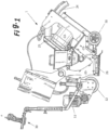
- a self propelled shot blasting machine 1 is shown in Figure 1 .
- the machine 1 sits on a pair of rear wheels 10 and a front drive wheel 12.
- Machine 1 is driven by an electric motor 11 coupled to drive wheel 12.
- the machine 1 has a second motor 13 that drives a blast wheel 14.
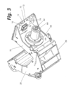
- the machine 1 also has a plenum 20 incorporating a hopper 22 and a housing 23 surrounding the blast wheel 14.
- the plenum 20 is coupled to one end of a vacuum tube 24 by a fitting (or port) 25.
- the other end of the vacuum tube 24 is coupled to a vacuum (not shown) .
- Hopper 22 is filled with shot prior to use.
- the vacuum is then energized to create air flow through the vacuum tube 24 and plenum 20.
- the motors 11 and 13 are then energized.
- Energizing motor 13 causes the blast wheel 14 to spin.
- Shot is metered from hopper 22 through a valve into the housing 23 where the blast wheel 14 is located.
- the blast wheel 14 accelerates the shot toward a spout opening 28 at the base of the housing 23 adjacent the floor and in an area contained by a suction head 26.
- the shot impacts the floor's surface roughening the surface, the shot, together with floor debris and dust, are carried through the plenum 20 by the air flow.
- the dust and debris are carried to the vacuum,
- the shot is deposited back into the hopper and recycled.
- Operation of the two motors 11 and 13 and the speed and direction of the machine are controlled by ergonomic controller 30.
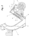
- the housing 23 has an interior chamber 52 in communication with spout opening 28.
- the housing 23 comprises a mounting plate 54 having an interior surface 56 facing the interior chamber 52, an exterior surface 58, and a drive shaft orifice 60.
- a blast wheel 14 is coupled to a drive shaft 62 and positioned within the interior chamber 52 of the housing 23.
- the drive shaft 62 extends from the blast wheel 14 through the drive shaft orifice 60.
- a bearing 64 is mounted to exterior surface 58 of the mounting plate 54. The bearing 64 surrounds a portion of the drive shaft 62 and encloses the drive shaft orifice 60.
- Motor 13 is coupled to the drive shaft 62.
- Various elements may be employed to couple the drive shaft 62 to the motor 13, for example a chain and a pair of sprockets, or a belt and a pair of pullies. In any case, the motor 13 turns the drive shaft 62 which, in turn, drives the blast wheel 14.
- a fan 70 is mounted outside of the interior chamber 52.
- the fan is 70 directed to create airflow across the exterior surface 58 of the mounting plate 54 and around the bearing 64. This fan dissipates heat from the interior chamber 52. More specifically, the air passing over the exterior surface 58 of the mounting plate 54 and around the bearing 64 draws heat away from these structures creating a greater temperature differential that causes heat from inside of the interior chamber 52 to be transmitted to the outside through the mounting plate 54 and bearing 64.
- the housing has at least one wall 72 extending at an angle from the mounting plate 54 adjacent the bearing 64.
- a wall may be present for various reasons, for example to reinforce the shot blaster assembly generally or to support specific structures of the assembly.
- the wall 72 will be positioned between the motor 13 and the bearing 64. When so positioned, the wall 72 directs heat generated by the motor 13 away from the area of the immediately adjacent the interior chamber 52 of the housing 23.
- the wall 72 no matter where positioned, may include one or more vents 74/75 that cooperate with the fan 70.
- the fan 70 has a suction side and a discharge side.
- the location of the wall 72 will dictate whether the suction side or discharge side of the fan 70 should face the vent(s) 74.
- air passes through the vents 74 before reaching the fan 70 and being blown by the fan 70 across the mounting plate 54 and around the bearing 64. This arrangement may be preferred when the wall is not between the motor and the bearing.
- the wall 72 is between the motor 13 and the bearing 64, it may be preferable to position the discharge side of the fan 70 toward the vent(s)74.
- the fan 70 includes a blade 76 and some means to rotate the blade to create airflow.
- the fan 70 will comprise a blade driven by an additional motor.
- the blade could also be driven by motor 13 without deviating from the invention.
- the fan 70 could be mounted to the drive shaft 62 to which the blast wheel 14 is mounted or to a separate drive shaft also driven by the motor 12.
- the fan blade will typically reside in an enclosure 77 that does not unduly impede air flow generated with the fan.
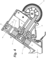
- FIG. 4 shows a shot blaster according to the present invention.
- This embodiment includes modifications to the blast wheel housing 23. Specifically, vents 80 and 81 have been added to the exterior walls of the blast wheel housing to provide air flow through the interior chamber 52 of the blast wheel housing 23.
- the blast wheel housing has been further modified to include a liner 84 between the blast wheel 14 and the vents 80 and 81.
- the liner 84 may be an imperforate metal sheet. When this is the case, only the region of the interior chamber 52 of blast wheel housing 23 between the liner 84 and the vents 80/81 is directly vented. Heat generated in other parts of the interior chamber 52 is dissipated via conduction through the liner 84 and then carried out of the housing 23 by air flow through vents 80/81. This airflow may be enhanced by employing a fan 82. Fan 82 is shown positioned within the interior chamber 52 of blast wheel housing 23 adjacent vent 81. The liner 84 separates the fan 82 from the blast wheel 14. As such, the liner 84 isolates and protects the fan 82 (and the vents 80/81) from shot flying off the blast wheel 14. The fan 82 could also be mounted outside of the housing 23 adjacent one of the vents 80/81 to make assembly easier.
- the liner 84 may be semi-permeable. Specifically, the liner 84 may be formed as a mesh with pores large enough to permit air to pass through the liner 84 and small enough to prevent shot or other particles flying off the blast wheel from passing through the liner 84.
- the blast wheel housing 23 is part of (or at least in fluid communication with) the plenum 20.
- the plenum 20 is coupled to a vacuum tube 24 which is attached to a vacuum (not shown).
- a vacuum not shown.
- the liner is semi-permeable and the vacuum is energized, the vacuum will draw air in through the vents 80/82., the liner 84, and the rest of the interior chamber 52. This air will exit the interior chamber 52 through the spout opening 28.
- the fan 81 may again be provided to enhance such air flow through the interior chamber and out the spout opening 28.
- direct vents such as 80/81 are provided and indirect vents such as 74/75 are provided.
- a direct vent is a vent that provides a flow path for air between the exterior of blast wheel housing 23 and the interior chamber 52; and an “indirect vent” is a vent that provides a flow path for air across exterior walls of the blast wheel housing 22 or other exterior structures associated with housing 23 that will conduct heat from the interior chamber 52 of blast wheel housing 23.
- Fans such as 82 may be provided to enhance air flow through the direct vents 80/81 and fans such as 70 may be provided to enhance air flow through the indirect vents 74/75.
Landscapes
- Engineering & Computer Science (AREA)
- Mechanical Engineering (AREA)
- Environmental & Geological Engineering (AREA)
- Structures Of Non-Positive Displacement Pumps (AREA)
- Arrangement And Driving Of Transmission Devices (AREA)
Claims (11)
- Ein Kugelstrahlgerät (1), welcher Folgendes umfasst:a. ein Gehäuse (23), das eine innere Kammer (52) definiert, wobei das Gehäuse (23) eine Montageplatte (54) umfasst, wobei die Montageplatte (54) eine innere Oberfläche (56), die der inneren Kammer (52) zugewandt ist, eine äußere Oberfläche (58) und eine Antriebswellenöffnung (60) umfasst;b. ein mit einer Antriebswelle (62) gekoppeltes Schleuderrad (14), wobei das Schleuderrad (14) in der Innenkammer (52) des Gehäuses (23) angeordnet ist und die Antriebswelle (62) sich von dem Schleuderrad (14) durch die Antriebswellenöffnung (60) erstreckt;c. ein Lager (64), das an der Außenfläche (58) der Montageplatte (54) angebracht ist, einen Teil der Antriebswelle (62) umgibt und die Öffnung (60) der Antriebswelle verschließt;d. einen ersten Motor (13), der mit der Antriebswelle (62) gekoppelt ist;e. eine erste direkte Entlüftung (80, 81), die einen Luftstrom zwischen einem Bereich außerhalb des Gehäuses und der Innenkammer des Gehäuses bereitstellt, um Wärme aus dem Inneren der Kammer abzuleiten, dadurch gekennzeichnet, dass das Gehäuse ferner eine Auskleidung (84) zwischen der direkten Entlüftung (80, 81) und dem Schleuderrad umfasst, um zu verhindern, dass Schrot durch die direkte Entlüftung (80, 81) aus dem Gehäuse austritt.
- Die Schleuderrad-Strahlanlage (1) nach Anspruch 1, wobei die Schleuderrad-Strahlanlage (1) ferner eine Sammelkammer (20) umfasst, die mit einem ersten Ende eines Vakuumrohrs (24) verbunden ist und einen Trichter (22) und das Gehäuse (23) umfasst, wobei das Gehäuse (23) ein Schleuderradgehäuse (23) ist.
- Die Schleuderrad-Strahlanlage (1) nach Anspruch 1 oder 2, wobei das Schleuderradgehäuse (23) ferner mindestens eine Wand umfasst, die eine Innenfläche, die der Innenkammer (52) zugewandt ist, und eine Außenfläche außerhalb der Schleuderrad-Strahlanlage (1) umfasst.
- Die Schleuderrad-Strahlanlage (1) nach Anspruch 3, wobei sich die erste direkte Entlüftung (80, 81) durch die mindestens eine Wand erstreckt und so ausgelegt ist, dass sie einen Luftstrom direkt zwischen der Innenkammer (52) des Schleuderradgehäuses (23) und der Atmosphäre außerhalb der Schleuderrad-Strahlanlage (1) bereitstellt.
- Die Schleuderrad-Strahlanlage (1) nach Anspruch 1, das ferner eine Wand (72), die sich von der Außenfläche (58) der Montageplatte (54) von dem Schleuderradgehäuse weg erstreckt, und mindestens eine indirekte Entlüftung (74, 75) umfasst, die sich durch die Wand (72) erstreckt.
- Die Schleuderrad-Strahlanlage (1) nach Anspruch 5, wobei die mindestens eine indirekte Entlüftung (74, 75) so ausgelegt ist, dass sie eine Einrichtung zum Bereitstellen eines Luftstroms zum Abführen von durch die Montageplatte (54) aus dem Inneren der Kammer geleiteter Wärme bereitstellt.
- Die Schleuderrad-Strahlanlage (1) nach einem der vorhergehenden Ansprüche umfasst ferner einen Lüfter (70), der außerhalb der inneren Kammer (52) angebracht ist und so ausgerichtet ist, dass er einen Luftstrom über die Außenfläche (58) der Montageplatte (54) und um das Lager herum erzeugt, um Wärme aus dem Inneren der Kammer abzuleiten.
- Die Schleuderrad-Strahlanlage (1) nach einem der vorhergehenden Ansprüche umfasst ferner einen Ventilator (82), der dazu ausgelegt ist, den Luftstrom durch die erste direkte Entlüftung (80, 81) zu verstärken.
- Die Schleuderrad-Strahlanlage (1) nach Anspruch 1 umfasst ferner mindestens eine zweite Entlüftung.
- Die Schleuderrad-Strahlanlage (1) nach Anspruch 9, wobei die mindestens eine zweite Entlüftung eine direkte Entlüftung ist und das Schleuderrad auf einer ersten Seite der Auskleidung positioniert ist und die mindestens eine erste direkte Entlüftung und die mindestens eine zweite direkte Entlüftung auf einer zweiten Seite der Auskleidung positioniert sind.
- Die Schleuderrad-Strahlanlage (1) nach Anspruch 10 umfasst ferner einen Ventilator (82), der so ausgelegt ist, dass er den Luftstrom durch die erste direkte Entlüftung (80) und die zweite direkte Entlüftung (81) verstärkt.
Applications Claiming Priority (3)
| Application Number | Priority Date | Filing Date | Title |
|---|---|---|---|
| US16/460,012 US11498184B2 (en) | 2019-07-02 | 2019-07-02 | Temperature control for blast wheel housing |
| EP20835203.9A EP3993953B1 (de) | 2019-07-02 | 2020-06-17 | Temperaturregelung für ein schleuderradgehäuse |
| PCT/US2020/038162 WO2021003023A1 (en) | 2019-07-02 | 2020-06-17 | Temperature control for blast wheel housing |
Related Parent Applications (2)
| Application Number | Title | Priority Date | Filing Date |
|---|---|---|---|
| EP20835203.9A Division-Into EP3993953B1 (de) | 2019-07-02 | 2020-06-17 | Temperaturregelung für ein schleuderradgehäuse |
| EP20835203.9A Division EP3993953B1 (de) | 2019-07-02 | 2020-06-17 | Temperaturregelung für ein schleuderradgehäuse |
Publications (3)
| Publication Number | Publication Date |
|---|---|
| EP4324596A2 EP4324596A2 (de) | 2024-02-21 |
| EP4324596A3 EP4324596A3 (de) | 2024-05-29 |
| EP4324596B1 true EP4324596B1 (de) | 2025-03-19 |
Family
ID=74066700
Family Applications (3)
| Application Number | Title | Priority Date | Filing Date |
|---|---|---|---|
| EP23218225.3A Active EP4335589B1 (de) | 2019-07-02 | 2020-06-17 | Schleuderstrahlvorrichtung |
| EP20835203.9A Active EP3993953B1 (de) | 2019-07-02 | 2020-06-17 | Temperaturregelung für ein schleuderradgehäuse |
| EP23219190.8A Active EP4324596B1 (de) | 2019-07-02 | 2020-06-17 | Ein sandstrahler |
Family Applications Before (2)
| Application Number | Title | Priority Date | Filing Date |
|---|---|---|---|
| EP23218225.3A Active EP4335589B1 (de) | 2019-07-02 | 2020-06-17 | Schleuderstrahlvorrichtung |
| EP20835203.9A Active EP3993953B1 (de) | 2019-07-02 | 2020-06-17 | Temperaturregelung für ein schleuderradgehäuse |
Country Status (4)
| Country | Link |
|---|---|
| US (3) | US11498184B2 (de) |
| EP (3) | EP4335589B1 (de) |
| PL (2) | PL4324596T3 (de) |
| WO (1) | WO2021003023A1 (de) |
Families Citing this family (2)
| Publication number | Priority date | Publication date | Assignee | Title |
|---|---|---|---|---|
| US11338674B2 (en) * | 2019-07-02 | 2022-05-24 | National Flooring Equipment, Inc. | Ergonomic control mechanism for self-propelled flooring equipment |
| SE546847C2 (en) * | 2023-04-05 | 2025-02-25 | Husqvarna Ab | A shot blasting machine with an improved liner system |
Family Cites Families (13)
| Publication number | Priority date | Publication date | Assignee | Title |
|---|---|---|---|---|
| GB920488A (en) * | 1960-11-09 | 1963-03-06 | Vacu Blast Ltd | Improved centrifugal wheel blasting machine |
| GB1477112A (en) * | 1974-10-10 | 1977-06-22 | Wheelabrator Frye Inc | Portable apparatus for blast cleaning |
| JPS51119591A (en) * | 1975-04-12 | 1976-10-20 | Hitachi Zosen Corp | Device of injecting polishing-sweeping material |
| US4199904A (en) * | 1977-12-02 | 1980-04-29 | The Carborundum Company | Retractable blast wheel carrier |
| SU812552A1 (ru) * | 1978-04-03 | 1981-03-15 | Курский Ордена Трудового Красногознамени Завод Тракторных Запасныхчастей Им.50-Летия Cccp | Дробеметный аппарат |
| GB1603308A (en) | 1978-05-19 | 1981-11-25 | Worldwide Blast Cleaning Ltd | Abrasive throwing machine |
| EP0041797A1 (de) | 1980-06-05 | 1981-12-16 | Parfloor Limited | Oberflächenbehandlung |
| US5024028A (en) | 1987-01-16 | 1991-06-18 | Midwest Blast Products, Inc. | Airless blast cleaning wheel and housing |
| US5231805A (en) * | 1991-07-01 | 1993-08-03 | Sander James P | Surface cleaning and asbestos removal machine |
| US5231850A (en) * | 1991-12-05 | 1993-08-03 | Richard Morris | Cooler container |
| KR200324381Y1 (ko) * | 2003-06-09 | 2003-08-25 | 이석재 | 고주파모터를 이용한 숏블라스트 |
| JP5663858B2 (ja) | 2009-11-06 | 2015-02-04 | 日立工機株式会社 | 携帯研磨機 |
| TWI529306B (zh) | 2013-11-15 | 2016-04-11 | 建準電機工業股份有限公司 | 氣體鼓風裝置 |
-
2019
- 2019-07-02 US US16/460,012 patent/US11498184B2/en active Active
-
2020
- 2020-06-17 EP EP23218225.3A patent/EP4335589B1/de active Active
- 2020-06-17 EP EP20835203.9A patent/EP3993953B1/de active Active
- 2020-06-17 EP EP23219190.8A patent/EP4324596B1/de active Active
- 2020-06-17 WO PCT/US2020/038162 patent/WO2021003023A1/en not_active Ceased
- 2020-06-17 PL PL23219190.8T patent/PL4324596T3/pl unknown
- 2020-06-17 PL PL20835203.9T patent/PL3993953T3/pl unknown
-
2022
- 2022-06-03 US US17/831,984 patent/US11618128B2/en active Active
- 2022-06-03 US US17/832,010 patent/US11685018B2/en active Active
Also Published As
| Publication number | Publication date |
|---|---|
| PL3993953T3 (pl) | 2024-06-24 |
| US20220297263A1 (en) | 2022-09-22 |
| EP3993953A1 (de) | 2022-05-11 |
| EP3993953B1 (de) | 2024-02-14 |
| US20210001448A1 (en) | 2021-01-07 |
| US20220288745A1 (en) | 2022-09-15 |
| WO2021003023A1 (en) | 2021-01-07 |
| EP4335589C0 (de) | 2025-08-27 |
| PL4324596T3 (pl) | 2025-06-23 |
| EP4324596A2 (de) | 2024-02-21 |
| EP3993953A4 (de) | 2022-11-30 |
| EP4335589A3 (de) | 2024-05-29 |
| US11685018B2 (en) | 2023-06-27 |
| US11618128B2 (en) | 2023-04-04 |
| US11498184B2 (en) | 2022-11-15 |
| EP4324596A3 (de) | 2024-05-29 |
| EP4335589A2 (de) | 2024-03-13 |
| EP4335589B1 (de) | 2025-08-27 |
Similar Documents
| Publication | Publication Date | Title |
|---|---|---|
| US11685018B2 (en) | Temperature control for blast wheel housing | |
| US3034262A (en) | Resurfacing and finishing machine | |
| US4377924A (en) | Portable device for treating surfaces | |
| US3934372A (en) | Portable upblast cleaning head | |
| KR950011052A (ko) | 건식 배럴 연마기 및 이를 이용하는 연마방법 | |
| US20110099748A1 (en) | Dust collection in a rotary floor finishing machine | |
| WO2012056597A1 (ja) | ブラスト加工装置 | |
| KR100646754B1 (ko) | 석재의 표면가공을 위한 쇼트 블라스트 장치 | |
| CN109012979B (zh) | 除粉除尘立轴式冲击破碎机及除粉除尘方法 | |
| US11628538B2 (en) | Valve mount for shot blaster plenum valve | |
| JP4893875B1 (ja) | ブラスト加工装置 | |
| US20100178854A1 (en) | Projector and Blasting Machine | |
| CN209975968U (zh) | 自吸式墙面平整设备 | |
| CN106272103B (zh) | 一种用于动车组制动系统安装管座模具自动喷砂的装置 | |
| KR200366331Y1 (ko) | 석재의 표면가공을 위한 쇼트 블라스트 장치 | |
| US20070032178A1 (en) | Shot blast machine | |
| KR101888161B1 (ko) | 직립형 쌀눈쌀 도정장치 | |
| KR102347333B1 (ko) | 연마용 제품회전장치 | |
| CN223591681U (zh) | 一种用于塑料颗粒除静电的输送装置 | |
| JPH0616641Y2 (ja) | ショツトブラスト装置 | |
| JP7554449B2 (ja) | 穀物乾燥装置 | |
| KR102571514B1 (ko) | 마이크로 연마재 정량 및 정압 공급시스템 | |
| JP2563343Y2 (ja) | ブラスト用研掃材投射装置 | |
| US20230364739A1 (en) | Blower for Floor Sander Drum | |
| US20070032179A1 (en) | Shot blast machine |
Legal Events
| Date | Code | Title | Description |
|---|---|---|---|
| PUAI | Public reference made under article 153(3) epc to a published international application that has entered the european phase |
Free format text: ORIGINAL CODE: 0009012 |
|
| STAA | Information on the status of an ep patent application or granted ep patent |
Free format text: STATUS: THE APPLICATION HAS BEEN PUBLISHED |
|
| AC | Divisional application: reference to earlier application |
Ref document number: 3993953 Country of ref document: EP Kind code of ref document: P |
|
| AK | Designated contracting states |
Kind code of ref document: A2 Designated state(s): AL AT BE BG CH CY CZ DE DK EE ES FI FR GB GR HR HU IE IS IT LI LT LU LV MC MK MT NL NO PL PT RO RS SE SI SK SM TR |
|
| REG | Reference to a national code |
Ref country code: DE Ref legal event code: R079 Free format text: PREVIOUS MAIN CLASS: B24C0001060000 Ref country code: DE Ref legal event code: R079 Ref document number: 602020048183 Country of ref document: DE Free format text: PREVIOUS MAIN CLASS: B24C0001060000 Ipc: B24C0005060000 |
|
| PUAL | Search report despatched |
Free format text: ORIGINAL CODE: 0009013 |
|
| AK | Designated contracting states |
Kind code of ref document: A3 Designated state(s): AL AT BE BG CH CY CZ DE DK EE ES FI FR GB GR HR HU IE IS IT LI LT LU LV MC MK MT NL NO PL PT RO RS SE SI SK SM TR |
|
| RIC1 | Information provided on ipc code assigned before grant |
Ipc: B24C 9/00 20060101ALN20240419BHEP Ipc: B24C 1/06 20060101ALI20240419BHEP Ipc: B24C 3/06 20060101ALI20240419BHEP Ipc: B23Q 11/12 20060101ALI20240419BHEP Ipc: B24C 5/06 20060101AFI20240419BHEP |
|
| STAA | Information on the status of an ep patent application or granted ep patent |
Free format text: STATUS: REQUEST FOR EXAMINATION WAS MADE |
|
| 17P | Request for examination filed |
Effective date: 20240524 |
|
| RIC1 | Information provided on ipc code assigned before grant |
Ipc: B24C 9/00 20060101ALN20240917BHEP Ipc: B24C 1/06 20060101ALI20240917BHEP Ipc: B24C 3/06 20060101ALI20240917BHEP Ipc: B23Q 11/12 20060101ALI20240917BHEP Ipc: B24C 5/06 20060101AFI20240917BHEP |
|
| GRAP | Despatch of communication of intention to grant a patent |
Free format text: ORIGINAL CODE: EPIDOSNIGR1 |
|
| STAA | Information on the status of an ep patent application or granted ep patent |
Free format text: STATUS: GRANT OF PATENT IS INTENDED |
|
| INTG | Intention to grant announced |
Effective date: 20241025 |
|
| RIN1 | Information on inventor provided before grant (corrected) |
Inventor name: KIVISTO, JOHN A. |
|
| RBV | Designated contracting states (corrected) |
Designated state(s): AL AT BE BG CH CY CZ DE DK EE ES FI FR GB GR HR HU IE IS IT LI LT LU LV MC MK MT NL NO PL PT RO RS SE SI SK SM TR |
|
| GRAS | Grant fee paid |
Free format text: ORIGINAL CODE: EPIDOSNIGR3 |
|
| GRAA | (expected) grant |
Free format text: ORIGINAL CODE: 0009210 |
|
| STAA | Information on the status of an ep patent application or granted ep patent |
Free format text: STATUS: THE PATENT HAS BEEN GRANTED |
|
| AC | Divisional application: reference to earlier application |
Ref document number: 3993953 Country of ref document: EP Kind code of ref document: P |
|
| AK | Designated contracting states |
Kind code of ref document: B1 Designated state(s): AL AT BE BG CH CY CZ DE DK EE ES FI FR GB GR HR HU IE IS IT LI LT LU LV MC MK MT NL NO PL PT RO RS SE SI SK SM TR |
|
| P01 | Opt-out of the competence of the unified patent court (upc) registered |
Free format text: CASE NUMBER: APP_6442/2025 Effective date: 20250207 |
|
| REG | Reference to a national code |
Ref country code: GB Ref legal event code: FG4D |
|
| REG | Reference to a national code |
Ref country code: CH Ref legal event code: EP |
|
| REG | Reference to a national code |
Ref country code: DE Ref legal event code: R096 Ref document number: 602020048183 Country of ref document: DE |
|
| REG | Reference to a national code |
Ref country code: IE Ref legal event code: FG4D |
|
| REG | Reference to a national code |
Ref country code: NL Ref legal event code: FP |
|
| PG25 | Lapsed in a contracting state [announced via postgrant information from national office to epo] |
Ref country code: RS Free format text: LAPSE BECAUSE OF FAILURE TO SUBMIT A TRANSLATION OF THE DESCRIPTION OR TO PAY THE FEE WITHIN THE PRESCRIBED TIME-LIMIT Effective date: 20250619 |
|
| PG25 | Lapsed in a contracting state [announced via postgrant information from national office to epo] |
Ref country code: FI Free format text: LAPSE BECAUSE OF FAILURE TO SUBMIT A TRANSLATION OF THE DESCRIPTION OR TO PAY THE FEE WITHIN THE PRESCRIBED TIME-LIMIT Effective date: 20250319 |
|
| REG | Reference to a national code |
Ref country code: LT Ref legal event code: MG9D |
|
| PG25 | Lapsed in a contracting state [announced via postgrant information from national office to epo] |
Ref country code: NO Free format text: LAPSE BECAUSE OF FAILURE TO SUBMIT A TRANSLATION OF THE DESCRIPTION OR TO PAY THE FEE WITHIN THE PRESCRIBED TIME-LIMIT Effective date: 20250619 |
|
| PG25 | Lapsed in a contracting state [announced via postgrant information from national office to epo] |
Ref country code: HR Free format text: LAPSE BECAUSE OF FAILURE TO SUBMIT A TRANSLATION OF THE DESCRIPTION OR TO PAY THE FEE WITHIN THE PRESCRIBED TIME-LIMIT Effective date: 20250319 |
|
| PG25 | Lapsed in a contracting state [announced via postgrant information from national office to epo] |
Ref country code: LV Free format text: LAPSE BECAUSE OF FAILURE TO SUBMIT A TRANSLATION OF THE DESCRIPTION OR TO PAY THE FEE WITHIN THE PRESCRIBED TIME-LIMIT Effective date: 20250319 |
|
| PG25 | Lapsed in a contracting state [announced via postgrant information from national office to epo] |
Ref country code: BG Free format text: LAPSE BECAUSE OF FAILURE TO SUBMIT A TRANSLATION OF THE DESCRIPTION OR TO PAY THE FEE WITHIN THE PRESCRIBED TIME-LIMIT Effective date: 20250319 Ref country code: GR Free format text: LAPSE BECAUSE OF FAILURE TO SUBMIT A TRANSLATION OF THE DESCRIPTION OR TO PAY THE FEE WITHIN THE PRESCRIBED TIME-LIMIT Effective date: 20250620 |
|
| REG | Reference to a national code |
Ref country code: AT Ref legal event code: MK05 Ref document number: 1776589 Country of ref document: AT Kind code of ref document: T Effective date: 20250319 |
|
| PG25 | Lapsed in a contracting state [announced via postgrant information from national office to epo] |
Ref country code: SE Free format text: LAPSE BECAUSE OF FAILURE TO SUBMIT A TRANSLATION OF THE DESCRIPTION OR TO PAY THE FEE WITHIN THE PRESCRIBED TIME-LIMIT Effective date: 20250319 |
|
| PG25 | Lapsed in a contracting state [announced via postgrant information from national office to epo] |
Ref country code: SM Free format text: LAPSE BECAUSE OF FAILURE TO SUBMIT A TRANSLATION OF THE DESCRIPTION OR TO PAY THE FEE WITHIN THE PRESCRIBED TIME-LIMIT Effective date: 20250319 |
|
| PG25 | Lapsed in a contracting state [announced via postgrant information from national office to epo] |
Ref country code: ES Free format text: LAPSE BECAUSE OF FAILURE TO SUBMIT A TRANSLATION OF THE DESCRIPTION OR TO PAY THE FEE WITHIN THE PRESCRIBED TIME-LIMIT Effective date: 20250319 Ref country code: PT Free format text: LAPSE BECAUSE OF FAILURE TO SUBMIT A TRANSLATION OF THE DESCRIPTION OR TO PAY THE FEE WITHIN THE PRESCRIBED TIME-LIMIT Effective date: 20250721 |
|
| PG25 | Lapsed in a contracting state [announced via postgrant information from national office to epo] |
Ref country code: AT Free format text: LAPSE BECAUSE OF FAILURE TO SUBMIT A TRANSLATION OF THE DESCRIPTION OR TO PAY THE FEE WITHIN THE PRESCRIBED TIME-LIMIT Effective date: 20250319 |
|
| PG25 | Lapsed in a contracting state [announced via postgrant information from national office to epo] |
Ref country code: CZ Free format text: LAPSE BECAUSE OF FAILURE TO SUBMIT A TRANSLATION OF THE DESCRIPTION OR TO PAY THE FEE WITHIN THE PRESCRIBED TIME-LIMIT Effective date: 20250319 Ref country code: EE Free format text: LAPSE BECAUSE OF FAILURE TO SUBMIT A TRANSLATION OF THE DESCRIPTION OR TO PAY THE FEE WITHIN THE PRESCRIBED TIME-LIMIT Effective date: 20250319 |
|
| PG25 | Lapsed in a contracting state [announced via postgrant information from national office to epo] |
Ref country code: RO Free format text: LAPSE BECAUSE OF FAILURE TO SUBMIT A TRANSLATION OF THE DESCRIPTION OR TO PAY THE FEE WITHIN THE PRESCRIBED TIME-LIMIT Effective date: 20250319 |
|
| PG25 | Lapsed in a contracting state [announced via postgrant information from national office to epo] |
Ref country code: SK Free format text: LAPSE BECAUSE OF FAILURE TO SUBMIT A TRANSLATION OF THE DESCRIPTION OR TO PAY THE FEE WITHIN THE PRESCRIBED TIME-LIMIT Effective date: 20250319 |
|
| PG25 | Lapsed in a contracting state [announced via postgrant information from national office to epo] |
Ref country code: IS Free format text: LAPSE BECAUSE OF FAILURE TO SUBMIT A TRANSLATION OF THE DESCRIPTION OR TO PAY THE FEE WITHIN THE PRESCRIBED TIME-LIMIT Effective date: 20250719 |