EP4322425B1 - Selbstkompensierender polarisationsmodulator - Google Patents
Selbstkompensierender polarisationsmodulator Download PDFInfo
- Publication number
- EP4322425B1 EP4322425B1 EP23186293.9A EP23186293A EP4322425B1 EP 4322425 B1 EP4322425 B1 EP 4322425B1 EP 23186293 A EP23186293 A EP 23186293A EP 4322425 B1 EP4322425 B1 EP 4322425B1
- Authority
- EP
- European Patent Office
- Prior art keywords
- polarization
- modulator
- optical signal
- phase
- designed
- Prior art date
- Legal status (The legal status is an assumption and is not a legal conclusion. Google has not performed a legal analysis and makes no representation as to the accuracy of the status listed.)
- Active
Links
Images

Classifications
-
- H—ELECTRICITY
- H04—ELECTRIC COMMUNICATION TECHNIQUE
- H04B—TRANSMISSION
- H04B10/00—Transmission systems employing electromagnetic waves other than radio-waves, e.g. infrared, visible or ultraviolet light, or employing corpuscular radiation, e.g. quantum communication
- H04B10/11—Arrangements specific to free-space transmission, i.e. transmission through air or vacuum
- H04B10/118—Arrangements specific to free-space transmission, i.e. transmission through air or vacuum specially adapted for satellite communication
-
- H—ELECTRICITY
- H04—ELECTRIC COMMUNICATION TECHNIQUE
- H04B—TRANSMISSION
- H04B10/00—Transmission systems employing electromagnetic waves other than radio-waves, e.g. infrared, visible or ultraviolet light, or employing corpuscular radiation, e.g. quantum communication
- H04B10/25—Arrangements specific to fibre transmission
- H04B10/2587—Arrangements specific to fibre transmission using a single light source for multiple stations
-
- G—PHYSICS
- G02—OPTICS
- G02B—OPTICAL ELEMENTS, SYSTEMS OR APPARATUS
- G02B27/00—Optical systems or apparatus not provided for by any of the groups G02B1/00 - G02B26/00, G02B30/00
- G02B27/28—Optical systems or apparatus not provided for by any of the groups G02B1/00 - G02B26/00, G02B30/00 for polarising
- G02B27/283—Optical systems or apparatus not provided for by any of the groups G02B1/00 - G02B26/00, G02B30/00 for polarising used for beam splitting or combining
-
- H—ELECTRICITY
- H04—ELECTRIC COMMUNICATION TECHNIQUE
- H04B—TRANSMISSION
- H04B10/00—Transmission systems employing electromagnetic waves other than radio-waves, e.g. infrared, visible or ultraviolet light, or employing corpuscular radiation, e.g. quantum communication
- H04B10/50—Transmitters
- H04B10/516—Details of coding or modulation
- H04B10/532—Polarisation modulation
Definitions
- the present description relates to optical signal generation and signal transmission, in particular the transmission of information by means of polarization modulation.
- the description relates to a modulator unit for modulating the polarization of an optical signal, an optical signal transmission path with such a modulator unit, and a system with such a modulator unit, for example in the form of a satellite.
- Information can be transmitted using technical means by assigning an information unit to a specific state of a carrier signal.
- the carrier signal is usually an electromagnetic wave from a specific spectral range.
- a property of the carrier signal is changed.
- the change itself or the state of the carrier signal after the change corresponds to the information to be transmitted.
- the carrier signal is usually changed at intervals in order to transmit several units of information.
- various physical characteristics of the carrier signal can be used as information carriers, for example: the amplitude, the frequency, the phase and/or the polarization. If one of these characteristics changes over time, this process is called modulation.
- Various technical components are used in the signal processing path to process the carrier signal and to incorporate the desired information into the carrier signal before the carrier signal is transmitted over the transmission path (wired or wireless).
- the components used in the preparation and processing of the carrier signal serve to modulate the carrier signal accordingly so that the information to be transmitted is correctly applied to the carrier signal and transmitted over the transmission path with as little interference and loss as possible.
- it can be considered a task to reduce or eliminate the influence of unwanted effects of a modulator unit on a carrier signal modulated for transmission.
- it can be considered a task to avoid polarization errors in a polarization-modulated optical signal.
- a modulator unit for modulating the polarization of an optical signal has a light source, a polarization-dependent phase modulator, and a reflector.
- the light source is designed to output an optical signal and to emit it as an input signal in the direction of the polarization-dependent phase modulator, wherein the optical signal contains a first polarization component with a first polarization direction and a second polarization component with a second polarization direction.
- the polarization-dependent phase modulator is designed to modulate a first phase of the first polarization component of the input signal in the first polarization direction and to forward the input signal modulated in this way to the reflector.
- the reflector is designed to retroreflect the optical signal received in the direction of the polarization-dependent phase modulator and in doing so to change the polarization of the optical signal (for example by 90°) so that the first polarization component with the first polarization direction receives the second polarization direction and the second polarization component with the second polarization direction receives the first polarization direction.
- the polarization-dependent phase modulator is designed to modulate a second phase of the second polarization component of the retroreflected optical signal in the first polarization direction.
- the modulator unit is designed to output the optical signal modulated in this way as a polarization-modulated output signal.
- the optical signal represents a superposition of two orthogonal polarization components.
- the polarization-dependent phase modulator is designed to apply different phases to both polarization components.
- the light source can be a light emitter (for example a laser) or the output of a light-guiding element.
- the optical signal travels through the same optical path of the modulator unit twice in opposite directions. On the way there, the optical signal travels from the light source through the polarization-dependent phase modulator to the reflector.
- the reflector retroreflects the optical signal and rotates the phase of the optical signal by 90° (either +90° or -90°).
- the reflector is implemented as a Faraday mirror, which is a retroreflector based on the Faraday effect that contains a crystal to which a magnetic field is applied and which rotates the polarization depending on the direction of propagation of the magnetic field.
- the reflector is therefore a combination of a Faraday rotator and a mirror.
- the optical signal first passes through the Faraday rotator and the polarization of the light is rotated by 45° (+45° or -45°).
- the optical signal is then mirrored and passes through the Faraday rotator again, rotating its polarization by another 45° (in the same direction as in the first step).
- the polarization of the retroreflected light then differs from the polarization of the incident light by 90°.
- the component of the optical signal with horizontal polarization (assumed as the first polarization direction for the example) is modulated (a first phase is applied to this component modulated) and the component with vertical polarization (assumed as the second polarization direction for the example) passes the polarization-dependent phase modulator without any changes to the phase of this component.
- the optical signal is retroreflected by the reflector and the polarization is rotated by 90°, the component with horizontal polarization is now vertically polarized, the component with vertical polarization is now horizontally polarized.
- the optical signal passes through the polarization-dependent phase modulator again, and now the (now) horizontally polarized component (which corresponds to the vertically polarized component of the outward path) is modulated in phase and the (now) vertically polarized component passes the polarization-dependent phase modulator without any further change in phase.
- the polarization-dependent phase modulator has only a single modulation axis, which remains the same on the outward and return paths, i.e. acts on the same polarization direction.
- the phase applied to the horizontally polarized component of the return path is called the second phase because on the return path the first phase is contained in the vertically polarized component of the optical signal and the first phase may be different from the second phase.
- both the vertically polarized component and the horizontally polarized component of the optical signal are modulated in a modulator unit with a single optical path.
- the resulting optical signal has received a desired polarization modulation in total by modulating the phase of the first polarization component with a first polarization direction on the outward path and the second polarization component, which has the first polarization direction on the return path, on the return path, although the polarization of the optical signal on the return path is changed by 90° compared to the outward path.
- the polarization-dependent phase modulator used here is a phase-changing modulator which acts on a polarization component of an optical signal, ie the polarization-dependent phase modulator changes the phase of two orthogonal polarization components of the optical light.
- the polarization-dependent phase modulator is an electro-optical modulator, EOM. It is to be understood that any reference to an EOM in this description is by way of example only and generally applies to a polarization-dependent phase modulator.
- the polarization-dependent phase modulator has two optical axes that are aligned orthogonally to one another. Using electrical energy, for example an applied voltage along one of these optical axes, its refractive index is modified, resulting in a phase change of the polarization component of the optical signal compared to the other or orthogonal optical axis.
- the structure of the modulator unit is very space-saving and compact.
- a polarization-dependent phase modulator can be switched very quickly, so that the modulator unit described here can be used up to high frequency ranges, for example several 10 GHz, such as up to 30 to 40 GHz or even higher frequency ranges.
- the modulator unit described here can be used to set different polarization states of an optical signal.
- different discrete states of polarization can be set by changing the phase of the horizontally polarized portion of the optical signal in relation to the phase of the vertically polarized portion of the optical signal.
- the polarization of the optical signal can be changed continuously as desired without being restricted to a limited number of polarization states.
- the polarization-dependent phase modulator comprises a crystal which is designed to be subjected to an electrical voltage and thereby to change its refractive index, whereby the phase of the first polarization component of the optical signal is changed.
- the refractive index can also be changed by applying a mechanical stress.
- the polarization-dependent phase modulator can, for example, contain a birefringent medium which, when a voltage is applied, changes the phase of an optical signal passing through the optical medium.
- the modulator unit is designed to vary the electrical voltage applied to the crystal over time.
- the modulator unit contains a power supply that provides a predeterminable electrical voltage.
- a control unit controls the power supply so that the latter provides a desired electrical voltage to the polarization-dependent phase modulator.
- the phase between differently polarized components of the optical signal is changed by the electrical voltage at the polarization-dependent phase modulator varying over time.
- an amount of the first phase of the first polarization component of the input signal in the first polarization direction differs from an amount of the second phase of the second polarization component of the retroreflected optical signal in the first polarization direction.
- the polarization-dependent phase modulator is designed to change a difference between the first phase and the second phase over time.
- the polarization of the output signal is also changed over time.
- the polarization of the output signal of the modulator unit can be freely adjusted between two linear polarizations (horizontal, vertical) and two circular polarizations (Z+ and Z-). However, the polarization can also be continuously adjusted to all elliptical states lying between the discrete states.
- the light source is designed to emit or output light with a well-defined optical mode.
- the polarization and coherence properties of the optical signal are important.
- the light source is a laser.
- Lasers are characterized by their ability to emit optical signals with a well-defined polarization. This makes them particularly suitable for applications such as those described here.
- the modulator unit is designed to control the light source such that the light source emits pulsed optical signals.
- a light pulse passes through the polarization-dependent phase modulator and a first polarization component is modulated in its phase.
- the light pulse is then passed on to the reflector, where the polarization of the light pulse is changed and the light pulse is reflected back to the polarization-dependent phase modulator.
- the polarization-dependent phase modulator again modulates a phase of a polarization component of the light pulse.
- the light pulse is designed in such a way that in the polarization-dependent phase modulator the light on the way to the reflector and the light on the way back from the reflector do not overlap.
- the light source can also emit a continuous light signal whose polarization is changed as described.
- the modulator unit may be configured to modulate and emit pulsed optical signals.
- the modulator unit may receive the pulsed optical signals from another source.
- the modulator unit further comprises a beam splitter which is arranged between the light source and the polarization-dependent phase modulator and is designed to direct at least a portion of the retroreflected optical signal phase-modulated by the polarization-dependent phase modulator in a predetermined direction.
- the beam splitter is arranged to at least partially structurally direct the optical signal output by the polarization-dependent phase modulator in a desired direction so that the optical signal output by the polarization-dependent phase modulator is not directed exclusively in the direction of the light source which supplies the input signal to the polarization-dependent Phase modulator emits.
- the output signal generated in this way carries information in its polarization that can be read and processed by a receiver.
- a circulator can be used instead of the beam splitter.
- an optical signal transmission path has a modulator unit as described herein and a receiver.
- the modulator unit functions as a signal source or part of a transmission unit which outputs an optical signal on which information is applied.
- the signal source sends the modulated optical signal in the direction of the receiver.
- the receiver is designed to receive optical signals.
- the modulator unit is arranged to emit the output signal in the direction of the receiver.
- the signal transmission path can be designed for unidirectional or bidirectional signal transmission.
- bidirectional signal transmission there are at least two communication units, both of which have both a modulator unit and a receiving unit.
- the modulator unit described here is implemented as part of an optical signal transmission path.
- the optical signal transmission path is thus set up to transmit information by means of polarization modulation of an optical carrier signal.
- the polarization modulation is introduced into the optical carrier signal by means of the modulator unit.
- the modulator unit intrinsically compensates for phase errors due to the components involved in the modulation because the optical signal passes through the same optical path twice and the orthogonal polarization components of the optical signal are modulated one after the other.
- the modulator unit is arranged in a satellite.
- the modulator unit can be arranged in any other communication system.
- a satellite having a modulator unit as described herein is provided.
- a modulator unit as described herein can be used, for example, on optical signal transmission links which are used between two mobile units (air, water or land vehicles or satellites), between a mobile unit and a counterpart on the earth's surface, or between two stationary units.
- Fig. 1 shows the structural design of a modulator unit 100.
- the modulator unit 100 contains a light source 110, a beam splitter 120, a beam absorber 125, a polarization-dependent phase modulator in the form of an electro-optical modulator, EOM, 130, and a reflector in the form of a Faraday mirror 140.
- the EOM 130 and the Faraday mirror 140 can be referred to together as a polarization modulator 105. Even if reference is made here to a Faraday mirror 140, for example, the corresponding explanations generally apply to a reflector mentioned herein.
- the light source 110 which is, for example, a laser, emits an optical signal in the form of the input signal 111.
- This input signal is fed to the other components and its polarization is modulated in order to transmit information via the optical signal.
- the information to be transmitted is modulated on the output signal 118 in the polarization of the optical signal.
- Fig. 2 the path of the optical signal through the modulator unit 100 is described. Reference is made to the state of the optical signal at different times or at different points in the modulator unit 100.
- the input signal 111 hits the beam splitter 120.
- the beam splitter 120 is designed as a non-polarizing beam splitter in this example.
- a part of the input signal 111 is directed as the first part 112 of the split input signal in the direction of the beam absorber 125 and another part of the Input signal 111 passes through beam splitter 120 as second part 113 of the split input signal in the direction of EOM 130.
- the EOM 130 now modulates a polarization component of the second part 113 of the optical signal by changing the phase of the portion of the signal 113 with a polarization.
- the optical signal is now present as a singly modulated signal 114, i.e. as an optical signal in which a polarization portion is modulated in phase.
- the Faraday mirror 140 retroreflects the singly modulated signal 114 and changes its polarization by 90°, so that the optical signal is reflected again to the EOM 130 as a mirrored signal 115.
- the horizontally polarized portion of the optical signal was modulated by the EOM on the outward path between signals 113 and 114, then on the return path this modulation is now in the vertically polarized portion of the optical signal 115 because the Faraday mirror 140 has changed the polarization by 90°. If the optical signal 115 now passes through the EOM 130 again on the return path, the now horizontally polarized portion (corresponds to the vertically polarized portion on the outward path, which did not experience any change in phase on the outward path) has its phase changed.
- the optical length between the EOM 130 and the Faraday mirror 140 is dimensioned such that an optical signal on the return path does not overlap an optical signal on the outward path within the EOM.
- the length of the optical path between the EOM and the Faraday mirror is dimensioned such that a light pulse on the return path does not overlap a light pulse on the outward path.
- the length of the optical path is matched to the duration of a light pulse and the transmission rate.
- the EOM thus applies a phase to both polarization components of the optical signal on the same optical path.
- the polarization of the optical signal can be varied.
- the optical signal 116 is now phase-modulated in both polarization components. The superposition of these two modulations results in the polarization of the optical signal 116, which contains the information to be transmitted.
- the optical signal 116 hits the beam splitter 120 again, a part 117 of the optical signal passes through the beam splitter and another part 118 is deflected in a different direction and corresponds to the output signal to be transmitted, in whose polarization the information to be transmitted is contained.
- the output signal passes through the beam splitter and the deflected signal is discarded.
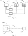
- Fig. 3 shows how the components of the modulator unit 100 are controlled in order to incorporate the information to be transmitted into the polarization of the optical signal.
- the modulator unit 100 contains a power supply 160 and a control unit 150. Both the power supply 160 and the control unit 150 are connected to the light source 110, the EOM 130 and the Faraday mirror 140. However, the control unit 150 can also be connected directly to the power supply 160 in order to specify an electrical voltage output by the power supply 160 at the respective connection.
- the power supply 160 supplies the light source 110 with electrical energy so that the light source generates the optical signal, which acts as an input signal. Furthermore, the power supply 160 supplies the EOM 130 with electrical energy, for example an electrical voltage, which is applied to a crystal 135. This electrical voltage influences the crystal 135 in such a way that the phase of a portion of a passing optical signal that is polarized in a certain way is changed. For example, variations in the electrical voltage can change the phase to different degrees.
- the control unit 150 and the energy supply 160 control the EOM in such a way that it acts on the optical signal passing through the EOM in the desired way on the outward and return paths of the optical signal and changes the phase of the influenced polarization component accordingly and as desired. The control unit and the energy supply must switch quickly enough and control the EOM.
- the polarization of a passing optical signal is changed in the Faraday rotator 143, in the present example by 45°.
- the optical signal then hits the mirror 145, is reflected by it and passes through the Faraday rotator 143 again. Now the polarization of the optical signal is changed again by 45° in the same direction, so that the polarization of the optical signal incident on the Faraday mirror and the polarization of the optical signal output by the Faraday mirror differ by 90°.
- the control unit 150 is designed to control the energy supply 160 and/or each of the components 110, 130, 140 such that these components are supplied with the energy required for their function.
- the control unit 150 can send control commands to the components 110, 130, 140 and/or control commands to the energy supply 160.
- Fig. 4 shows an optical signal transmission path 200.
- a modulator unit 100 functions as a signal source or transmitter.
- the modulator unit 100 modulates the polarization of an optical signal as described above and sends the modulated optical signal via a transmission path 210.
- the transmission path 210 is, for example, a wireless optical path.
- the modulated optical signal is received and processed by a remote station.
- the remote station is the receiver 220.
- the modulator unit 100 can be arranged on board a satellite.
- the receiver 220 can be arranged on the earth's surface or on board another satellite.
Landscapes
- Physics & Mathematics (AREA)
- Electromagnetism (AREA)
- Engineering & Computer Science (AREA)
- Computer Networks & Wireless Communication (AREA)
- Signal Processing (AREA)
- General Physics & Mathematics (AREA)
- Optics & Photonics (AREA)
- Astronomy & Astrophysics (AREA)
- Optical Communication System (AREA)
Description
- Die vorliegende Beschreibung betrifft optische Signalerzeugung und Signalübertragung, insbesondere die Übertragung von Informationen mittels Polarisationsmodulation. Im Speziellen betrifft die Beschreibung eine Modulatoreinheit zum Modulieren der Polarisation eines optischen Signals, eine optische Signalübertragungsstrecke mit einer solchen Modulatoreinheit, und ein System mit einer solchen Modulatoreinheit, beispielsweise in Form eines Satelliten.
- Informationen können mit technischen Mitteln übertragen werden, indem eine Informationseinheit einem bestimmten Zustand eines Trägersignals zugewiesen wird. Das Trägersignal ist üblicherweise eine elektromagnetische Welle aus einem spezifischen spektralen Bereich. Um nun eine Information auf das Trägersignal aufzuprägen, wird eine Eigenschaft des Trägersignals geändert. Die Änderung an sich oder der Zustand des Trägersignals nach der Änderung entsprechen dabei der zu übertragenden Information. Üblicherweise wird das Trägersignal in zeitlichen Abständen geändert, um hierdurch mehrere Informationseinheiten zu übertragen.
- Als Informationsträger kommen je nach Trägersignal verschiedene physikalische Merkmale des Trägersignals in Frage, beispielsweise: die Amplitude, die Frequenz, die Phase und/oder die Polarisation. Wird eines dieser Merkmale über der Zeit verändert, so wird dieser Vorgang als Modulation bezeichnet.
- Auf dem Signalverarbeitungspfad kommen verschiedene technische Komponenten zum Einsatz, um das Trägersignal zu bearbeiten und die gewünschte Information in das Trägersignal einzubringen, bevor das Trägersignal über die Übertragungsstrecke (leitungsgebunden oder leitungslos) übertragen wird.
- Die bei der Vorbereitung und Bearbeitung des Trägersignals verwendeten Komponenten dienen dazu, das Trägersignal entsprechend zu modulieren, damit die zu übertragende Information richtig auf das Trägersignal aufgebracht wird und mit möglichst wenig Störungen und Verlusten über die Übertragungsstrecke übertragen wird.
- Nun kann es aber vorkommen, dass neben der gewollten Modulation (Veränderung des Trägersignals) auch ungewollte Veränderungen des Trägersignals erfolgen, beispielsweise durch parasitäre Effekte oder andere ungewollte Eigenschaften der in die Vorbereitung des Trägersignals involvierten Komponenten. In dem Fall ist es bei einem Empfänger des Trägersignals nicht immer erkennbar, welche Veränderung des Trägersignals auf der gewollten Modulation basiert und welche Veränderung von ungewollten Effekten hervorgerufen wurde. Dadurch kann die Güte des Signals negativ beeinflusst werden.
- Ausgehend davon kann es als Aufgabe betrachtet werden, den Einfluss von ungewollten Effekten einer Modulatoreinheit auf ein zur Übertragung moduliertes Trägersignal zu reduzieren oder zu eliminieren. Es kann insbesondere als Aufgabe betrachtet werden, Polarisationsfehler bei einem polarisationsmodulierten optischen Signal zu vermeiden.
- Diese Aufgabe wird gelöst durch den Gegenstand des unabhängigen Anspruchs. Weitere Ausführungsformen ergeben sich aus den abhängigen Ansprüchen sowie aus der folgenden Beschreibung.
- Gemäß einem Aspekt ist eine Modulatoreinheit zum Modulieren der Polarisation eines optischen Signals angegeben. Die Modulatoreinheit weist eine Lichtquelle, einen polarisationsabhängigen Phasenmodulator, und einen Reflektor auf. Die Lichtquelle ist ausgestaltet, ein optisches Signal auszugeben und als Eingangssignal in Richtung des polarisationsabhängigen Phasenmodulators zu emittieren, wobei das optische Signal eine erste Polarisationskomponente mit einer ersten Polarisationsrichtung und eine zweite Polarisationskomponente mit einer zweiten Polarisationsrichtung enthält. Der polarisationsabhängige Phasenmodulator ist ausgestaltet, eine erste Phase der ersten Polarisationskomponente des Eingangssignals in der ersten Polarisationsrichtung zu modulieren und das so modulierte Eingangssignal an den Reflektor weiterzuleiten. Der Reflektor ist ausgestaltet, das erhaltene optische Signal in Richtung des polarisationsabhängigen Phasenmodulators zu retroreflektieren und dabei die Polarisation des optischen Signals zu verändern (beispielsweise um 90°), so dass die erste Polarisationskomponente mit der ersten Polarisationsrichtung die zweite Polarisationsrichtung erhält und die zweite Polarisationskomponente mit der zweiten Polarisationsrichtung die erste Polarisationsrichtung erhält. Der polarisationsabhängige Phasenmodulator ist ausgestaltet, eine zweite Phase der zweiten Polarisationskomponente des retroreflektierten optischen Signals in der ersten Polarisationsrichtung zu modulieren. Die Modulatoreinheit ist ausgestaltet, das so modulierte optische Signal als polarisationsmoduliertes Ausgangssignal auszugeben.
- Das optische Signal stellt eine Überlagerung aus zwei orthogonalen Polarisationskomponenten dar. Der polarisationsabhängige Phasenmodulator ist ausgestaltet, unterschiedliche Phasen auf beide Polarisationskomponenten aufzubringen.
- Grundsätzlich kann die Lichtquelle ein Lichtemitter sein (beispielsweise ein Laser) oder der Ausgang eines lichtführenden Elements. In einem Ausführungsbeispiel durchläuft das optische Signal denselben optischen Pfad der Modulatoreinheit zweimal in entgegengesetzte Richtungen. Auf dem Hinweg läuft das optische Signal von der Lichtquelle durch den polarisationsabhängigen Phasenmodulator zu dem Reflektor. Der Reflektor retroreflektiert das optische Signal und dreht die Phase des optischen Signals dabei um 90° (entweder +90° oder -90°). Beispielsweise ist der Reflektor als Faraday-Spiegel implementiert, der ein auf dem Faraday-Effekt beruhender Retroreflektor ist, der einen Kristall enthält, an welchem ein Magnetfeld anliegt und der die Polarisation in Abhängigkeit von der Ausbreitungsrichtung des Magnetfeldes dreht. Wenn beispielsweise horizontal polarisiertes Licht auf den Reflektor trifft, wird dies als vertikal polarisiertes Licht retroreflektiert. Es handelt sich also bei dem Reflektor um die Kombination aus einem Faraday-Rotator und einem Spiegel. Der Faraday-Rotator wird zunächst von dem optischen Signal passiert und die Polarisation des Lichts wird dabei um 45° (+45° oder -45°) gedreht. Dann wird das optische Signal gespiegelt und passiert erneut den Faraday-Rotator, wobei seine Polarisation um weitere 45° (in dieselbe Richtung wie im ersten Schritt) gedreht wird. In Summe unterscheidet sich dann die Polarisation des retroreflektierten Lichts von der Polarisation des einfallenden Lichts um 90°.
- Gerade weil das optische Signal denselben optischen Pfad mit getauschten Polarisationsrichtungen zweimal durchläuft, werden parasitäre Einflüsse der Modulatoreinheit auf die Phase des optischen Signals und Fehlerphasen eliminiert, insbesondere Phasenfehler, welche durch langsame thermische und mechanische Fluktuationen der Modulatoreinheit, insbesondere auf der Strecke ab einschließlich dem polarisationsabhängigen Phasenmodulator bis zu einschließlich dem Reflektor, aber auch vor dem polarisationsabhängigen Phasenmodulator, auftreten.
- Auf dem Hinweg wird beispielsweise die Komponente des optischen Signals mit horizontaler Polarisation (für das Beispiel als erste Polarisationsrichtung angenommen) moduliert (es wird eine erste Phase auf diese Komponente moduliert) und die Komponente mit vertikaler Polarisation (für das Beispiel als zweite Polarisationsrichtung angenommen) passiert den polarisationsabhängigen Phasenmodulator, ohne dass Veränderungen an der Phase dieser Komponente vorgenommen werden. Nun wird das optische Signal von dem Reflektor retroreflektiert und die Polarisation um 90° gedreht, die Komponente mit horizontaler Polarisation ist nun vertikal polarisiert, die Komponente mit vertikaler Polarisation ist nun horizontal polarisiert. Auf dem Rückweg durchläuft das optische Signal erneut den polarisationsabhängigen Phasenmodulator, und nun wird die (jetzt) horizontal polarisierte Komponente (welche der vertikal polarisierten Komponente des Hinwegs entspricht) in seiner Phase moduliert und die (jetzt) vertikal polarisierte Komponente passiert den polarisationsabhängigen Phasenmodulator ohne weitere Änderung seiner Phase. Dies bedeutet, dass der polarisationsabhängige Phasenmodulator nur eine einzelne Modulationsachse hat, welche auf dem Hin- und Rückweg gleichbleibt, also auf dieselbe Polarisationsrichtung wirkt.
- Wird auf dem Hinweg eine Fehlerphase (oder Fehlphasenverschiebung) in das optische Signal eingebracht, indem beispielsweise die Phase der horizontal polarisierten Komponente auf andere Weise als die Phase der vertikal polarisierten Komponente parasitär beeinflusst wird, so hebt sich diese Fehlerphase auf dem Rückweg auf, weil das optische Signal mit einer um 90° gedrehten Polarisation denselben optischen Pfad durchläuft und die gleiche Fehlerphase nun auf die jeweils andere Polarisationsachse aufgetragen wird. Hierdurch werden alle relativen Phasenfehler auf gleiche Weise in beide Polarisationsachsen eingebracht.
- Die Phase, welche auf die horizontal polarisierte Komponente des Rückwegs aufgebracht wird, wird als zweite Phase bezeichnet, weil auf dem Rückweg die erste Phase in der vertikal polarisierten Komponente des optischen Signals enthalten ist und die erste Phase gegenüber der zweiten Phase unterschiedlich sein kann.
- In dem hier wiedergegeben Beispiel wird in einer bestimmten Weise auf horizontal und vertikal polarisierte Komponenten des optischen Signals Bezug genommen, nämlich dass auf dem Hin- und Rückweg durch den polarisationsabhängigen Phasenmodulator jeweils die horizontal polarisierte Komponente phasenmoduliert wird. Es versteht sich allerdings, dass dieses Beispiel nicht einschränkend ist und der polarisationsabhängigen Phasenmodulator statt der horizontal polarisierten Komponente die vertikal polarisierte Komponente oder eine beliebige andere Komponente des optischen Signals phasenmodulieren kann. Entscheidend ist, dass zwischen den beiden Vorgängen, bei denen die Phase einer Polarisationskomponente des optischen Signals moduliert wird, die Polarisation des optischen Signals um 90° gedreht wird.
- Im Ergebnis werden bei diesem Aufbau sowohl die vertikal polarisierte Komponente als auch die horizontal polarisierte Komponente des optischen Signals in einer Modulatoreinheit mit einem einzelnen optischen Pfad moduliert. Das resultierende optische Signal hat in Summe eine gewünschte Polarisationsmodulation erhalten, indem auf dem Hinweg die erste Polarisationskomponente mit einer ersten Polarisationsrichtung und auf dem Rückweg die zweite Polarisationskomponente, welche auf dem Rückweg die erste Polarisationsrichtung hat, in ihrer Phase moduliert werden, wobei jedoch die Polarisation des optischen Signals auf dem Rückweg im Vergleich zum Hinweg um 90° verändert ist.
- Der hier verwendete polarisationsabhängige Phasenmodulator ist ein phasenverändernder Modulator, welcher auf eine Polarisationskomponente eines optischen Signals wirkt, d.h. dass der polarisationsabhängige Phasenmodulator die Phase zweier orthogonal zueinander stehender Polarisationskomponenten des optischen Lichts verändert. Beispielsweise ist der polarisationsabhängige Phasenmodulator ein elektro-optischer Modulator, EOM. Es ist zu verstehen, dass jegliche Bezugnahme auf einen EOM in dieser Beschreibung lediglich beispielhaft erfolgt und grundsätzlich für einen polarisationsabhängigen Phasenmodulator gilt.
- Beispielsweise hat der polarisationsabhängige Phasenmodulator zwei orthogonal zueinander ausgerichtete optische Achsen. Mittels elektrischer Energie, beispielsweise einer angelegten Spannung entlang einer dieser optischen Achsen, wird deren Brechungsindex modifiziert und es resultiert eine Phasenveränderung der Polarisationskomponente des optischen Signals gegenüber der anderen bzw. orthogonalen optischen Achse.
- Durch die Verwendung eines Faraday-Spiegels ist der Aufbau der Modulatoreinheit sehr platzsparend und kompakt. Ein polarisationsabhängiger Phasenmodulator kann sehr schnell geschaltet werden, so dass die hier beschriebene Modulatoreinheit bis in hohe Frequenzbereiche verwendet werden kann, beispielsweise mehrere 10 GHz, wie z.B. bis hin zu 30 bis 40 GHz oder auch höheren Frequenzbereichen.
- Mit der hier beschriebenen Modulatoreinheit lassen sich verschiedene Polarisationszustände eines optischen Signals einstellen. Hierbei können beispielsweise verschiedene diskrete Zustände der Polarisation eingestellt werden, indem die Phase des horizontal polarisierten Anteils des optischen Signals mit Bezug zu der Phase des vertikal polarisierten Anteils des optischen Signals verändert wird. Die Polarisation des optischen Signals kann aber grundsätzlich beliebig kontinuierlich verändert werden, ohne auf eine beschränkte Anzahl von Polarisationszuständen begrenzt zu sein.
- Gemäß einer Ausführungsform weist der polarisationsabhängige Phasenmodulator einen Kristall auf, welcher ausgestaltet ist, mit einer elektrischen Spannung beaufschlagt zu werden und dabei seinen Brechungsindex zu verändern, wodurch die Phase der ersten Polarisationskomponente des optischen Signals verändert wird. Der Brechungsindex kann aber auch verändert werden, indem eine mechanische Spannung beaufschlagt wird.
- Der polarisationsabhängige Phasenmodulator kann beispielsweise ein doppelbrechendes Medium enthalten, welches bei Anlegen einer Spannung die Phase eines durch das optische Medium passierenden optischen Signals verändert.
- Gemäß einer weiteren Ausführungsform ist die Modulatoreinheit ausgestaltet, die an dem Kristall anliegende elektrische Spannung über der Zeit zu variieren.
- Beispielsweise enthält die Modulatoreinheit eine Energieversorgung, welche eine vorgebbare elektrische Spannung bereitstellt. Eine Steuereinheit steuert die Energieversorgung an, damit letztere eine gewünschte elektrische Spannung an den polarisationsabhängigen Phasenmodulator bereitstellt. Durch die über der Zeit variierende elektrische Spannung an dem polarisationsabhängigen Phasenmodulator wird die Phase zwischen unterschiedlich polarisierten Komponenten des optischen Signals verändert.
- Gemäß einer weiteren Ausführungsform unterscheidet sich ein Betrag der ersten Phase der ersten Polarisationskomponente des Eingangssignals in der ersten Polarisationsrichtung von einem Betrag der zweiten Phase der zweiten Polarisationskomponente des retroreflektierten optischen Signals in der ersten Polarisationsrichtung.
- In anderen Worten bedeutet dies, dass der polarisationsabhängige Phasenmodulator auf dem Hinweg eine andere Phase auf die horizontal polarisierte Komponente des optischen Signals moduliert als auf dem Rückweg auf die dann horizontal polarisierte Komponente des retroreflektierten Signals. Dadurch verändert sich die Polarisation des Ausgangssignals der Modulatoreinheit.
- Gemäß einer weiteren Ausführungsform ist der polarisationsabhängige Phasenmodulator ausgestaltet, einen Unterschied zwischen der ersten Phase und der zweiten Phase über der Zeit zu verändern.
- Indem der polarisationsabhängige Phasenmodulator den Unterschied der Phasen auf dem Hinweg und dem Rückweg über der Zeit verändert, wird die Polarisation des Ausgangssignals ebenfalls über der Zeit verändert.
- Insgesamt ist die Polarisation des Ausgangssignals der Modulatoreinheit frei einstellbar zwischen zwei linearen Polarisationen (horizontal, vertikal) und zwei zirkularen Polarisationen (Z+ und Z-). Die Polarisation kann aber auch kontinuierlich auf sämtliche zwischen den diskreten Zuständen liegenden elliptischen Zustände eingestellt werden.
- Gemäß einer weiteren Ausführungsform ist die Lichtquelle ausgestaltet, Licht mit einer wohldefinierten optischen Mode zu emittieren oder auszugeben. In dem vorliegenden Zusammenhang sind die Polarisations- und Kohärenzeigenschaften des optischen Signals von Bedeutung. Beispielsweise ist die Lichtquelle ein Laser.
- Laser zeichnen sich dadurch aus, dass sie optische Signale mit einer wohldefinierten Polarisation emittieren können. Damit eignen sie sich insbesondere für Anwendungen wie hier beschrieben.
- Gemäß einer weiteren Ausführungsform ist die Modulatoreinheit ausgestaltet, die Lichtquelle so anzusteuern, dass die Lichtquelle gepulste optische Signale emittiert.
- Ein Lichtpuls passiert den polarisationsabhängigen Phasenmodulator und eine erste Polarisationskomponente wird in ihrer Phase moduliert. Sodann wird der Lichtpuls weiter zu dem Reflektor geleitet, dort wird die Polarisation des Lichtpulses geändert und der Lichtpuls zurück zu dem polarisationsabhängigen Phasenmodulator reflektiert. Auf dem Rückweg moduliert der polarisationsabhängige Phasenmodulator erneut eine Phase einer Polarisationskomponente des Lichtpulses auf.
- Der Lichtpuls ist beispielsweise so ausgelegt, dass in dem polarisationsabhängigen Phasenmodulator das Licht auf dem Hinweg zu dem Reflektor und das Licht auf dem Rückweg von dem Reflektor sich nicht überlagern.
- Abgesehen von der Verwendung von gepulsten Lichtsignalen kann die Lichtquelle auch ein kontinuierliches Lichtsignal aussenden, dessen Polarisation wie beschrieben verändert wird.
- In einer anderen Ausführungsform kann die Modulatoreinheit so ausgestaltet sein, dass sie gepulste optische Signale moduliert und emittiert. In diesem Beispiel kann die Modulatoreinheit die gepulsten optischen Signale von einer anderen Quelle erhalten.
- Gemäß einer weiteren Ausführungsform weist die Modulatoreinheit weiterhin einen Strahlteiler auf, welcher zwischen der Lichtquelle und dem polarisationsabhängigen Phasenmodulator angeordnet ist und ausgestaltet ist, mindestens einen Teil des von dem polarisationsabhängigen Phasenmodulator phasenmodulierten retroreflektierten optischen Signals in eine vorgegebene Richtung zu lenken.
- Der Strahlteiler ist angeordnet, um das von dem polarisationsabhängigen Phasenmodulator ausgegebene optische Signal mindestens teilweise strukturell in eine gewünschte Richtung zu lenken, damit das von dem polarisationsabhängigen Phasenmodulator ausgegebene optische Signal nicht ausschließlich in Richtung der Lichtquelle, welche das Eingangssignal zu dem polarisationsabhängigen Phasenmodulator emittiert, abgibt. Das so erzeugte Ausgangssignal trägt in seiner Polarisation eine Information, die auf Seiten eines Empfängers ausgelesen und verarbeitet werden kann.
- In einer Variante kann anstelle des Strahlteilers auch ein Zirkulator genutzt werden.
- Gemäß einem weiteren Aspekt ist eine optische Signalübertragungsstrecke angegeben. Die optische Signalübertragungsstrecke weist eine Modulatoreinheit wie hierin beschrieben und einen Empfänger auf. Die Modulatoreinheit fungiert als Signalquelle bzw. Teil einer Sendeeinheit, welche ein optisches Signal ausgibt, auf dem eine Information aufgebracht ist. Die Signalquelle sendet das modulierte optische Signal in Richtung des Empfängers. Der Empfänger ist ausgestaltet, optische Signale zu empfangen. Die Modulatoreinheit ist angeordnet, das Ausgangssignal in Richtung des Empfängers zu emittieren.
- Die Signalübertragungsstrecke kann für unidirektionale oder bidirektionale Signalübertragung ausgestaltet sein. Im Falle der bidirektionalen Signalübertragung gibt es mindestens zwei Kommunikationseinheiten, welche beide sowohl eine Modulatoreinheit als auch eine Empfangseinheit aufweisen.
- Die hierin beschriebene Modulatoreinheit ist als Teil einer optischen Signalübertragungsstrecke implementiert. Damit ist die optische Signalübertragungsstrecke eingerichtet, Informationen mittels Polarisationsmodulation eines optischen Trägersignals zu übertragen. Die Polarisationsmodulation wird mittels der Modulatoreinheit in das optische Trägersignal eingebracht. Die Modulatoreinheit kompensiert Phasenfehler auf Grund der an der Modulation beteiligten Komponenten intrinsisch, weil das optische Signal denselben optischen Pfad zweimal durchläuft und dabei die orthogonal aufeinander stehenden Polarisationskomponenten des optischen Signals nacheinander moduliert werden.
- Gemäß einer Ausführungsform ist die Modulatoreinheit in einem Satelliten angeordnet. Die Modulatoreinheit kann aber in jeglichem anderen Kommunikationssystem angeordnet sein.
- Gemäß einem weiteren Aspekt ist ein Satellit mit einer Modulatoreinheit wie hierin beschrieben angegeben.
- Eine Modulatoreinheit wie hierin beschrieben kann beispielsweise auf optischen Signalübertragungsstrecken verwendet werden, welche zwischen zwei mobilen Einheiten (Luft-, Wasser- oder Landfahrzeuge oder Satelliten), zwischen einer mobilen Einheit und einer Gegenstelle auf der Erdoberfläche, oder zwischen zwei stationären Einheiten zum Einsatz kommen.
- Nachfolgend wird anhand der beigefügten Zeichnungen näher auf Ausführungsbeispiele eingegangen. Die Darstellungen sind schematisch und nicht maßstabsgetreu. Gleiche Bezugszeichen beziehen sich auf gleiche oder ähnliche Elemente. Es zeigen:
- Fig. 1
- eine schematische Darstellung einer Modulatoreinheit.
- Fig. 2
- eine schematische Darstellung des optischen Pfads durch eine Modulatoreinheit.
- Fig. 3
- eine schematische Darstellung einer Modulatoreinheit.
- Fig. 4
- eine schematische Darstellung einer optischen Signalübertragungsstrecke.
-
Fig. 1 zeigt den strukturellen Aufbau einer Modulatoreinheit 100. Die Modulatoreinheit 100 enthält eine Lichtquelle 110, einen Strahlteiler 120, einen Strahlabsorber 125, einen polarisationsabhängigen Phasenmodulator in Form eines elektro-optischen Modulators, EOM, 130, sowie einen Reflektor in Form eines Faraday-Spiegels 140. Der EOM 130 und der Faraday-Spiegel 140 können gemeinsam als Polarisationsmodulator 105 bezeichnet werden. Auch wenn hier beispielsweise auf einen Faraday-Spiegel 140 Bezug genommen wird, so gelten die entsprechenden Erläuterungen allgemein für einen hierin genannten Reflektor. - Die Lichtquelle 110, welche beispielsweise ein Laser ist, emittiert ein optisches Signal in Form des Eingangssignals 111. Dieses Eingangssignal wird den übrigen Komponenten zugeführt und seine Polarisation wird moduliert, um über das optische Signal Informationen zu übertragen.
- Die zu übertragenden Informationen sind auf dem Ausgangssignal 118 in der Polarisation des optischen Signals moduliert.
- Wie die Polarisation des optischen Signals moduliert wird, wird nun mit Bezug zu
Fig. 2 , welche ergänzend zuFig. 1 zu betrachten ist, beschrieben. - In
Fig. 2 wird der Weg des optischen Signals durch die Modulatoreinheit 100 beschrieben. Dabei wird auf den Zustand des optischen Signals zu verschiedenen Zeitpunkten bzw. an verschiedenen Punkten in der Modulatoreinheit 100 Bezug genommen. - Zunächst trifft das Eingangssignal 111 auf den Strahlteiler 120. Der Strahlteiler 120 ist in diesem Beispiel als nichtpolarisierender Strahlteiler ausgestaltet. Ein Teil des Eingangssignals 111 wird als erster Teil 112 des aufgeteilten Eingangssignals in Richtung des Strahlabsorbers 125 gelenkt und ein anderer Teil des Eingangssignals 111 passiert den Strahlteiler 120 als zweiter Teil 113 des aufgeteilten Eingangssignals in Richtung des EOM 130.
- Der EOM 130 moduliert nun eine Polarisationskomponente des zweiten Teils 113 des optischen Signals, indem der Anteil des Signals 113 mit einer Polarisation in seiner Phase verändert wird. Am Ausgang des EOM liegt das optische Signal nun als einfachmoduliertes Signal 114 vor, also als optisches Signal, bei dem ein Polarisationsanteil in der Phase moduliert ist.
- Der Faraday-Spiegel 140 retroreflektiert das einfachmodulierte Signal 114 und verändert dabei seine Polarisation um 90°, so dass das optische Signal als gespiegeltes Signal 115 erneut zu dem EOM 130 reflektiert wird.
- Wenn beispielsweise auf dem Hinweg zwischen den Signalen 113 und 114 durch den EOM der horizontal polarisierte Anteil des optischen Signals moduliert wurde, dann steckt auf dem Rückweg diese Modulation nun in dem vertikal polarisierten Anteil des optischen Signals 115, weil der Faraday-Spiegel 140 die Polarisation um 90° verändert hat. Durchläuft das optische Signal 115 nun auf dem Rückweg erneut den EOM 130, so wird der nun horizontal polarisierte Anteil (entspricht dem vertikal polarisierten Anteil auf dem Hinweg, der auf dem Hinweg keine Änderung seiner Phase erfahren hat) in seiner Phase verändert.
- Die optische Länge zwischen dem EOM 130 und dem Faraday-Spiegel 140 ist so bemessen, dass ein optisches Signal auf dem Rückweg nicht ein optisches Signal auf dem Hinweg innerhalb des EOMs überlagert. Allgemein ausgedrückt ist die Länge des optischen Pfads zwischen EOM und Faraday-Spiegel so bemessen, dass ein Lichtpuls auf dem Rückweg einen Lichtpuls auf dem Hinweg nicht überlagert. Insbesondere ist die Länge des optischen Pfads auf die Dauer eines Lichtpulses und die Übertragungsrate abgestimmt.
- Somit werden durch den EOM auf demselben optischen Pfad beide Polarisationsanteile des optischen Signals mit einer Phase beaufschlagt. Indem die entsprechende Phase auf dem Hinweg und Rückweg vorgegeben wird, kann die Polarisation des optischen Signals variiert werden.
- Das optische Signal 116 ist nun in beiden Polarisationskomponenten phasenmoduliert. Aus der Überlagerung dieser beiden Modulationen ergibt sich die Polarisation des optischen Signals 116, in welcher die zu übertragende Information enthalten ist.
- Nun trifft das optische Signal 116 erneut auf den Strahlteiler 120, ein Teil 117 des optischen Signals passiert den Strahlteiler und ein weiterer Teil 118 wird in eine andere Richtung abgelenkt und entspricht dem zu übertragenden Ausgangssignal, in dessen Polarisation die zu übertragende Information enthalten ist. Alternativ ist denkbar, dass das Ausgangssignal den Strahlteiler passiert und das abgelenkte Signal verworfen wird.
-
Fig. 3 stellt dar, wie die Komponenten der Modulatoreinheit 100 angesteuert werden, um die zu übertragende Information in die Polarisation des optischen Signals einzubringen. - Die Modulatoreinheit 100 enthält eine Energieversorgung 160 und eine Steuereinheit 150. Sowohl die Energieversorgung 160 als auch die Steuereinheit 150 ist mit der Lichtquelle 110, dem EOM 130 und dem Faraday-Spiegel 140 verbunden. Die Steuereinheit 150 kann aber auch direkt mit der Energieversorgung 160 verbunden sein, um eine von der Energieversorgung 160 an dem jeweiligen Anschluss ausgegebene elektrische Spannung vorzugeben.
- Die Energieversorgung 160 versorgt die Lichtquelle 110 mit elektrischer Energie, damit die Lichtquelle das optische Signal, welches als Eingangssignal fungiert, erzeugt. Weiterhin versorgt die Energieversorgung 160 den EOM 130 mit elektrischer Energie, beispielsweise einer elektrischen Spannung, die an einem Kristall 135 anliegt. Diese elektrische Spannung beeinflusst den Kristall 135 dahingehend, dass die Phase eines auf bestimmte Weise polarisierten Anteils eines passierenden optischen Signals verändert wird. Beispielsweise können Variationen der elektrischen Spannung die Phase unterschiedlich stark verändern. Die Steuereinheit 150 und die Energieversorgung 160 steuern den EOM so an, dass dieser auf dem Hinweg und dem Rückweg des optischen Signals auf die gewünschte Weise auf das den EOM passierende optische Signal wirkt und die Phase der beeinflussten Polarisationskomponente entsprechend und wie gewünscht verändert. Hierbei muss die Steuereinheit und die Energieversorgung entsprechend schnell schalten und den EOM ansteuern.
- Die Polarisation eines passierenden optischen Signals wird in dem Faraday-Rotator 143 verändert, im vorliegenden Beispiel um 45°. Dann trifft das optische Signal auf den Spiegel 145, wird davon reflektiert und passiert erneut den Faraday-Rotator 143. Nun wird die Polarisation des optischen Signals erneut um 45° in dieselbe Richtung verändert, so dass sich die Polarisation der in den Faraday-Spiegel einfallenden optischen Signals und die Polarisation des von dem Faraday-Spiegel ausgegebenen optischen Signals um 90° unterscheidet.
- Die Steuereinheit 150 ist ausgestaltet, die Energieversorgung 160 und/oder jede einzelne der Komponenten 110, 130, 140 so anzusteuern, dass diese Komponenten mit der für ihre Funktion benötigten Energie versorgt werden. Hierzu kann die Steuereinheit 150 Steuerkommandos an die Komponenten 110, 130, 140 und/oder Steuerkommandos an die Energieversorgung 160 senden.
-
Fig. 4 zeigt eine optische Signalübertragungsstrecke 200. Eine Modulatoreinheit 100 fungiert als Signalquelle bzw. Sender. Die Modulatoreinheit 100 moduliert die Polarisation eines optischen Signals wie oben beschrieben und sendet das modulierte optische Signal über einen Übertragungspfad 210. Der Übertragungspfad 210 ist beispielsweise ein leitungsloser optischer Pfad. - Das modulierte optische Signal wird von einer Gegenstelle empfangen und verarbeitet. Bei der Gegenstelle handelt es sich um den Empfänger 220. Die Modulatoreinheit 100 kann an Bord eines Satelliten angeordnet sein. Der Empfänger 220 kann auf der Erdoberfläche oder an Bord eines anderen Satelliten angeordnet sein.
- Ergänzend ist darauf hinzuweisen, dass "umfassend" oder "aufweisend" keine anderen Elemente oder Schritte ausschließt und "eine" oder "ein" keine Vielzahl ausschließt. Ferner sei darauf hingewiesen, dass Merkmale oder Schritte, die mit Verweis auf eines der obigen Ausführungsbeispiele beschrieben worden sind, auch in Kombination mit anderen Merkmalen oder Schritten anderer oben beschriebener Ausführungsbeispiele verwendet werden können. Bezugszeichen in den Ansprüchen sind nicht als Einschränkung anzusehen.
-
- 100
- Modulatoreinheit
- 105
- Polarisationsmodulator
- 110
- Lichtquelle
- 111
- Eingangssignal
- 112
- erster Teil des aufgeteilten Eingangssignals
- 113
- zweiter Teil des aufgeteilten Eingangssignals
- 114
- einfachmoduliertes Signal
- 115
- gespiegeltes Signal
- 116
- zweifachmoduliertes Signal
- 117
- abgezweigtes Signal
- 118
- Ausgangssignal
- 120
- Strahlteiler
- 125
- Strahlabsorber
- 130
- polarisationsabhängiger Phasenmodulator, elektro-optischer Modulator
- 135
- Kristall
- 140
- Reflektor, Faraday-Spiegel
- 143
- Faraday-Rotator
- 145
- Spiegel
- 150
- Steuereinheit
- 160
- Energieversorgung
- 200
- optische Signalübertragungsstrecke
- 210
- Übertragungspfad, optisches Signal
- 220
- Empfänger
- 300
- Satellit
Claims (10)
- Modulatoreinheit (100) zum Modulieren der Polarisation eines optischen Signals, aufweisend:eine Lichtquelle (110);einen polarisationsabhängigen Phasenmodulator (130);einen Reflektor (140);wobei die Lichtquelle (110) ausgestaltet ist, ein optisches Signal auszugeben und als Eingangssignal (111) in Richtung des polarisationsabhängigen Phasenmodulators (130) zu emittieren, wobei das optische Signal eine erste Polarisationskomponente mit einer ersten Polarisationsrichtung und eine zweite Polarisationskomponente mit einer zweiten Polarisationsrichtung enthält;wobei der polarisationsabhängige Phasenmodulator (130) ausgestaltet ist, eine erste Phase der ersten Polarisationskomponente des Eingangssignals (111) in der ersten Polarisationsrichtung zu modulieren und das so modulierte Eingangssignal an den Reflektor (140) weiterzuleiten;dadurch gekennzeichnet, dassder Reflektor (140) ausgestaltet ist, das erhaltene optische Signal in Richtung des polarisationsabhängigen Phasenmodulators (130) zu retroreflektieren und dabei seine Polarisation zu verändern, so dass die erste Polarisationskomponente mit der ersten Polarisationsrichtung die zweite Polarisationsrichtung erhält und die zweite Polarisationskomponente mit der zweiten Polarisationsrichtung die erste Polarisationsrichtung erhält;wobei der polarisationsabhängige Phasenmodulator (130) ausgestaltet ist, eine zweite Phase der zweiten Polarisationskomponente des retroreflektierten optischen Signals in der ersten Polarisationsrichtung zu modulieren;wobei die Modulatoreinheit (100) ausgestaltet ist, das so modulierte optische Signal als polarisationsmoduliertes Ausgangssignal (118) auszugeben.
- Modulatoreinheit (100) nach Anspruch 1,
wobei der polarisationsabhängige Phasenmodulator (130) einen Kristall (135) aufweist, welcher ausgestaltet ist, mit einer elektrischen Spannung beaufschlagt zu werden und dabei seinen Brechungsindex zu verändern, wodurch die Phase der ersten Polarisationskomponente des optischen Signals verändert wird. - Modulatoreinheit (100) nach Anspruch 2,
wobei die Modulatoreinheit (100) ausgestaltet ist, die an dem Kristall (135) anliegende elektrische Spannung über der Zeit zu variieren. - Modulatoreinheit (100) nach einer der voranstehenden Ansprüche,
wobei ein Betrag der ersten Phase der ersten Polarisationskomponente des Eingangssignals (111) in der ersten Polarisationsrichtung sich von einem Betrag der zweiten Phase der zweiten Polarisationskomponente des retroreflektierten optischen Signals in der ersten Polarisationsrichtung unterscheidet. - Modulatoreinheit (100) nach Anspruch 4,
wobei der polarisationsabhängige Phasenmodulator (130) ausgestaltet ist, einen Unterschied zwischen der ersten Phase und der zweiten Phase über der Zeit zu verändern. - Modulatoreinheit (100) nach einem der voranstehenden Ansprüche,
wobei die Lichtquelle (110) ausgestaltet ist, Licht mit einer definierten optischen Mode auszugeben. - Modulatoreinheit (100) nach einem der voranstehenden Ansprüche,
wobei die Modulatoreinheit (100) ausgestaltet ist, die Lichtquelle (110) so anzusteuern, dass die Lichtquelle (110) gepulste optische Signale emittiert. - Modulatoreinheit (100) nach einem der voranstehenden Ansprüche,
weiterhin aufweisend einen Strahlteiler (120), welcher zwischen der Lichtquelle (110) und dem polarisationsabhängigen Phasenmodulator (130) angeordnet ist und ausgestaltet ist, mindestens einen Teil des von dem polarisationsabhängigen Phasenmodulator (130) phasenmodulierten retroreflektierten optischen Signals in eine vorgegebene Richtung zu lenken. - Optische Signalübertragungsstrecke (200), aufweisendeine Modulatoreinheit (100) nach einem der Ansprüche 1 bis 8;einen Empfänger (220), welcher ausgestaltet ist, optische Signale zu empfangen;wobei die Modulatoreinheit (100) angeordnet ist, das Ausgangssignal (118) in Richtung des Empfängers (220) zu emittieren.
- Satellit (300) mit einer Modulatoreinheit (100) nach einem der Ansprüche 1 bis 8.
Applications Claiming Priority (1)
| Application Number | Priority Date | Filing Date | Title |
|---|---|---|---|
| DE102022119077.3A DE102022119077B3 (de) | 2022-07-29 | 2022-07-29 | Modulatoreinheit zum Modulieren der Polarisation eines optischen Signals, optische Signalübertragungsstrecke sowie Satellit |
Publications (2)
| Publication Number | Publication Date |
|---|---|
| EP4322425A1 EP4322425A1 (de) | 2024-02-14 |
| EP4322425B1 true EP4322425B1 (de) | 2024-11-27 |
Family
ID=87419222
Family Applications (1)
| Application Number | Title | Priority Date | Filing Date |
|---|---|---|---|
| EP23186293.9A Active EP4322425B1 (de) | 2022-07-29 | 2023-07-19 | Selbstkompensierender polarisationsmodulator |
Country Status (4)
| Country | Link |
|---|---|
| US (1) | US20240039633A1 (de) |
| EP (1) | EP4322425B1 (de) |
| DE (1) | DE102022119077B3 (de) |
| ES (1) | ES3017133T3 (de) |
Family Cites Families (2)
| Publication number | Priority date | Publication date | Assignee | Title |
|---|---|---|---|---|
| JP3567763B2 (ja) * | 1998-06-12 | 2004-09-22 | Kddi株式会社 | 光送信装置 |
| US6333808B1 (en) | 2000-04-28 | 2001-12-25 | Alcatel | Optical signal scrambling |
-
2022
- 2022-07-29 DE DE102022119077.3A patent/DE102022119077B3/de active Active
-
2023
- 2023-07-19 ES ES23186293T patent/ES3017133T3/es active Active
- 2023-07-19 EP EP23186293.9A patent/EP4322425B1/de active Active
- 2023-07-28 US US18/227,509 patent/US20240039633A1/en active Pending
Also Published As
| Publication number | Publication date |
|---|---|
| US20240039633A1 (en) | 2024-02-01 |
| ES3017133T3 (en) | 2025-05-12 |
| EP4322425A1 (de) | 2024-02-14 |
| DE102022119077B3 (de) | 2023-10-05 |
Similar Documents
| Publication | Publication Date | Title |
|---|---|---|
| DE69526019T2 (de) | Synchrone Polarisations-und-Phasenmodulation zur verbesserten Leistung eines optischen Übertragungssystems | |
| DE69331167T2 (de) | Optischer Impulsgeber | |
| DE69221121T2 (de) | Programmierbare faseroptische verzögerungsleitung, und damit ausgestattetes radarzielsimulationssystem | |
| EP0461380B1 (de) | Funk-Nachrichtenübertragungssystem, insbesondere zellulares Mobilfunksystem | |
| DE69633816T2 (de) | Synchrone Polarisations- und Phasenmodulation mit einer periodischen Wellenform mit harmonischen Oberschwingungen zur Leistungsverbesserung von optischen Übertragungssystemen | |
| DE69332131T2 (de) | Optischer Modulator, optischer Sender und optisches Übertragungssystem | |
| DE10208712A1 (de) | Phasengesteuerte Antennengruppe mit einer verstärkungsgeschalteten Multi-Mode-Fabry-Perot-Laserdiode und einer Faser hoher Dispersion | |
| EP0354567A2 (de) | Sende/Empfangsteil für ein bidirektionales kohärent-optisches übertragungssystem | |
| DE3637809A1 (de) | Sender fuer kohaerente lichtwellen | |
| DE102017127813A1 (de) | Strahlausrichtung in unidirektionalen optischen Kommunikationssystemen | |
| DE19856586A1 (de) | Optischer Modulator mit einem Isolator und optischer Sender, der diesen umfaßt | |
| DE69801709T2 (de) | Optisches Übertragungssystem mit dynamischer Kompensation der übertragenen Leistung | |
| EP0883253B1 (de) | Verfahren und Anordnung zur Optimierung von optischen Intersatellitenverbindungen | |
| EP4322425B1 (de) | Selbstkompensierender polarisationsmodulator | |
| DE69017359T2 (de) | Verfahren und Vorrichtung zur Übertragung eines elektromagnetischen Signals in einer optischen Faser. | |
| EP4380076B1 (de) | Polarisationsmodulator mit getrennten optischen teilstrecken | |
| DE1564072B2 (de) | Regelung der frequenznachfuehrung bei gegeneinander bewegten optischen sendern und hierfuer geeignete regelvorrichtung | |
| EP4328660B1 (de) | Selbstkompensierender polarisationsmodulator mit direktionalem phasenschieber | |
| DE69129977T2 (de) | Optischer Sender | |
| DE69012528T2 (de) | Vorrichtung zur kontinuierlichen Abstimmung einer kohärenten und linear polarisierten Lichtquelle. | |
| DE3713340A1 (de) | Verfahren zur optischen nachrichtenuebertragung | |
| EP0612451B1 (de) | Einrichtung für die erzeugung von rückkopplungssignalen zur regelung optischer überwachungskreise (pll) | |
| DE69703180T2 (de) | Optisches Übertragungssystem mit optischen Verstärkern und Verstärkung abhängig von der Eingangssignalpolarisation | |
| DE69109150T2 (de) | Verfahren und Vorrichtung zum Korrigieren der Amplitudenvariation in elektrooptischen Lasersystemen. | |
| EP4593325A1 (de) | Vorrichtung zum generieren von mindestens einem quantensicheren schlüssel unter verwendung von time-bin-kodierung und/oder polarisations-kodierung sowie verfahren zum generieren von mindestens einem quantensicheren schlüssel |
Legal Events
| Date | Code | Title | Description |
|---|---|---|---|
| PUAI | Public reference made under article 153(3) epc to a published international application that has entered the european phase |
Free format text: ORIGINAL CODE: 0009012 |
|
| STAA | Information on the status of an ep patent application or granted ep patent |
Free format text: STATUS: THE APPLICATION HAS BEEN PUBLISHED |
|
| STAA | Information on the status of an ep patent application or granted ep patent |
Free format text: STATUS: REQUEST FOR EXAMINATION WAS MADE |
|
| AK | Designated contracting states |
Kind code of ref document: A1 Designated state(s): AL AT BE BG CH CY CZ DE DK EE ES FI FR GB GR HR HU IE IS IT LI LT LU LV MC ME MK MT NL NO PL PT RO RS SE SI SK SM TR |
|
| 17P | Request for examination filed |
Effective date: 20240122 |
|
| RBV | Designated contracting states (corrected) |
Designated state(s): AL AT BE BG CH CY CZ DE DK EE ES FI FR GB GR HR HU IE IS IT LI LT LU LV MC ME MK MT NL NO PL PT RO RS SE SI SK SM TR |
|
| GRAP | Despatch of communication of intention to grant a patent |
Free format text: ORIGINAL CODE: EPIDOSNIGR1 |
|
| STAA | Information on the status of an ep patent application or granted ep patent |
Free format text: STATUS: GRANT OF PATENT IS INTENDED |
|
| RIC1 | Information provided on ipc code assigned before grant |
Ipc: H04B 10/00 20130101AFI20240624BHEP |
|
| INTG | Intention to grant announced |
Effective date: 20240716 |
|
| GRAS | Grant fee paid |
Free format text: ORIGINAL CODE: EPIDOSNIGR3 |
|
| GRAA | (expected) grant |
Free format text: ORIGINAL CODE: 0009210 |
|
| STAA | Information on the status of an ep patent application or granted ep patent |
Free format text: STATUS: THE PATENT HAS BEEN GRANTED |
|
| AK | Designated contracting states |
Kind code of ref document: B1 Designated state(s): AL AT BE BG CH CY CZ DE DK EE ES FI FR GB GR HR HU IE IS IT LI LT LU LV MC ME MK MT NL NO PL PT RO RS SE SI SK SM TR |
|
| REG | Reference to a national code |
Ref country code: GB Ref legal event code: FG4D Free format text: NOT ENGLISH |
|
| REG | Reference to a national code |
Ref country code: CH Ref legal event code: EP |
|
| REG | Reference to a national code |
Ref country code: IE Ref legal event code: FG4D Free format text: LANGUAGE OF EP DOCUMENT: GERMAN |
|
| REG | Reference to a national code |
Ref country code: DE Ref legal event code: R096 Ref document number: 502023000335 Country of ref document: DE |
|
| REG | Reference to a national code |
Ref country code: LT Ref legal event code: MG9D |
|
| REG | Reference to a national code |
Ref country code: NL Ref legal event code: MP Effective date: 20241127 |
|
| PG25 | Lapsed in a contracting state [announced via postgrant information from national office to epo] |
Ref country code: IS Free format text: LAPSE BECAUSE OF FAILURE TO SUBMIT A TRANSLATION OF THE DESCRIPTION OR TO PAY THE FEE WITHIN THE PRESCRIBED TIME-LIMIT Effective date: 20250327 Ref country code: PT Free format text: LAPSE BECAUSE OF FAILURE TO SUBMIT A TRANSLATION OF THE DESCRIPTION OR TO PAY THE FEE WITHIN THE PRESCRIBED TIME-LIMIT Effective date: 20250327 Ref country code: HR Free format text: LAPSE BECAUSE OF FAILURE TO SUBMIT A TRANSLATION OF THE DESCRIPTION OR TO PAY THE FEE WITHIN THE PRESCRIBED TIME-LIMIT Effective date: 20241127 |
|
| PG25 | Lapsed in a contracting state [announced via postgrant information from national office to epo] |
Ref country code: FI Free format text: LAPSE BECAUSE OF FAILURE TO SUBMIT A TRANSLATION OF THE DESCRIPTION OR TO PAY THE FEE WITHIN THE PRESCRIBED TIME-LIMIT Effective date: 20241127 Ref country code: NL Free format text: LAPSE BECAUSE OF FAILURE TO SUBMIT A TRANSLATION OF THE DESCRIPTION OR TO PAY THE FEE WITHIN THE PRESCRIBED TIME-LIMIT Effective date: 20241127 |
|
| PG25 | Lapsed in a contracting state [announced via postgrant information from national office to epo] |
Ref country code: BG Free format text: LAPSE BECAUSE OF FAILURE TO SUBMIT A TRANSLATION OF THE DESCRIPTION OR TO PAY THE FEE WITHIN THE PRESCRIBED TIME-LIMIT Effective date: 20241127 |
|
| PG25 | Lapsed in a contracting state [announced via postgrant information from national office to epo] |
Ref country code: NO Free format text: LAPSE BECAUSE OF FAILURE TO SUBMIT A TRANSLATION OF THE DESCRIPTION OR TO PAY THE FEE WITHIN THE PRESCRIBED TIME-LIMIT Effective date: 20250227 |
|
| PG25 | Lapsed in a contracting state [announced via postgrant information from national office to epo] |
Ref country code: LV Free format text: LAPSE BECAUSE OF FAILURE TO SUBMIT A TRANSLATION OF THE DESCRIPTION OR TO PAY THE FEE WITHIN THE PRESCRIBED TIME-LIMIT Effective date: 20241127 |
|
| PG25 | Lapsed in a contracting state [announced via postgrant information from national office to epo] |
Ref country code: PL Free format text: LAPSE BECAUSE OF FAILURE TO SUBMIT A TRANSLATION OF THE DESCRIPTION OR TO PAY THE FEE WITHIN THE PRESCRIBED TIME-LIMIT Effective date: 20241127 |
|
| PG25 | Lapsed in a contracting state [announced via postgrant information from national office to epo] |
Ref country code: RS Free format text: LAPSE BECAUSE OF FAILURE TO SUBMIT A TRANSLATION OF THE DESCRIPTION OR TO PAY THE FEE WITHIN THE PRESCRIBED TIME-LIMIT Effective date: 20250227 |
|
| REG | Reference to a national code |
Ref country code: ES Ref legal event code: FG2A Ref document number: 3017133 Country of ref document: ES Kind code of ref document: T3 Effective date: 20250512 |
|
| PG25 | Lapsed in a contracting state [announced via postgrant information from national office to epo] |
Ref country code: SM Free format text: LAPSE BECAUSE OF FAILURE TO SUBMIT A TRANSLATION OF THE DESCRIPTION OR TO PAY THE FEE WITHIN THE PRESCRIBED TIME-LIMIT Effective date: 20241127 |
|
| PG25 | Lapsed in a contracting state [announced via postgrant information from national office to epo] |
Ref country code: DK Free format text: LAPSE BECAUSE OF FAILURE TO SUBMIT A TRANSLATION OF THE DESCRIPTION OR TO PAY THE FEE WITHIN THE PRESCRIBED TIME-LIMIT Effective date: 20241127 |
|
| PG25 | Lapsed in a contracting state [announced via postgrant information from national office to epo] |
Ref country code: EE Free format text: LAPSE BECAUSE OF FAILURE TO SUBMIT A TRANSLATION OF THE DESCRIPTION OR TO PAY THE FEE WITHIN THE PRESCRIBED TIME-LIMIT Effective date: 20241127 |
|
| PG25 | Lapsed in a contracting state [announced via postgrant information from national office to epo] |
Ref country code: RO Free format text: LAPSE BECAUSE OF FAILURE TO SUBMIT A TRANSLATION OF THE DESCRIPTION OR TO PAY THE FEE WITHIN THE PRESCRIBED TIME-LIMIT Effective date: 20241127 |
|
| PG25 | Lapsed in a contracting state [announced via postgrant information from national office to epo] |
Ref country code: SK Free format text: LAPSE BECAUSE OF FAILURE TO SUBMIT A TRANSLATION OF THE DESCRIPTION OR TO PAY THE FEE WITHIN THE PRESCRIBED TIME-LIMIT Effective date: 20241127 |
|
| PG25 | Lapsed in a contracting state [announced via postgrant information from national office to epo] |
Ref country code: CZ Free format text: LAPSE BECAUSE OF FAILURE TO SUBMIT A TRANSLATION OF THE DESCRIPTION OR TO PAY THE FEE WITHIN THE PRESCRIBED TIME-LIMIT Effective date: 20241127 |
|
| REG | Reference to a national code |
Ref country code: DE Ref legal event code: R097 Ref document number: 502023000335 Country of ref document: DE |
|
| PG25 | Lapsed in a contracting state [announced via postgrant information from national office to epo] |
Ref country code: SE Free format text: LAPSE BECAUSE OF FAILURE TO SUBMIT A TRANSLATION OF THE DESCRIPTION OR TO PAY THE FEE WITHIN THE PRESCRIBED TIME-LIMIT Effective date: 20241127 |
|
| PLBE | No opposition filed within time limit |
Free format text: ORIGINAL CODE: 0009261 |
|
| STAA | Information on the status of an ep patent application or granted ep patent |
Free format text: STATUS: NO OPPOSITION FILED WITHIN TIME LIMIT |
|
| PGFP | Annual fee paid to national office [announced via postgrant information from national office to epo] |
Ref country code: ES Payment date: 20250828 Year of fee payment: 3 |
|
| PGFP | Annual fee paid to national office [announced via postgrant information from national office to epo] |
Ref country code: DE Payment date: 20250722 Year of fee payment: 3 |
|
| PGFP | Annual fee paid to national office [announced via postgrant information from national office to epo] |
Ref country code: IT Payment date: 20250731 Year of fee payment: 3 |
|
| PGFP | Annual fee paid to national office [announced via postgrant information from national office to epo] |
Ref country code: FR Payment date: 20250725 Year of fee payment: 3 Ref country code: AT Payment date: 20251020 Year of fee payment: 3 |
|
| 26N | No opposition filed |
Effective date: 20250828 |