EP4380076B1 - Polarisationsmodulator mit getrennten optischen teilstrecken - Google Patents
Polarisationsmodulator mit getrennten optischen teilstrecken Download PDFInfo
- Publication number
- EP4380076B1 EP4380076B1 EP23210231.9A EP23210231A EP4380076B1 EP 4380076 B1 EP4380076 B1 EP 4380076B1 EP 23210231 A EP23210231 A EP 23210231A EP 4380076 B1 EP4380076 B1 EP 4380076B1
- Authority
- EP
- European Patent Office
- Prior art keywords
- polarization
- polarization component
- optical
- phase
- modulator
- Prior art date
- Legal status (The legal status is an assumption and is not a legal conclusion. Google has not performed a legal analysis and makes no representation as to the accuracy of the status listed.)
- Active
Links
Images
Classifications
-
- G—PHYSICS
- G02—OPTICS
- G02F—OPTICAL DEVICES OR ARRANGEMENTS FOR THE CONTROL OF LIGHT BY MODIFICATION OF THE OPTICAL PROPERTIES OF THE MEDIA OF THE ELEMENTS INVOLVED THEREIN; NON-LINEAR OPTICS; FREQUENCY-CHANGING OF LIGHT; OPTICAL LOGIC ELEMENTS; OPTICAL ANALOGUE/DIGITAL CONVERTERS
- G02F1/00—Devices or arrangements for the control of the intensity, colour, phase, polarisation or direction of light arriving from an independent light source, e.g. switching, gating or modulating; Non-linear optics
- G02F1/01—Devices or arrangements for the control of the intensity, colour, phase, polarisation or direction of light arriving from an independent light source, e.g. switching, gating or modulating; Non-linear optics for the control of the intensity, phase, polarisation or colour
- G02F1/0136—Devices or arrangements for the control of the intensity, colour, phase, polarisation or direction of light arriving from an independent light source, e.g. switching, gating or modulating; Non-linear optics for the control of the intensity, phase, polarisation or colour for the control of polarisation, e.g. state of polarisation [SOP] control, polarisation scrambling, TE-TM mode conversion or separation
-
- G—PHYSICS
- G02—OPTICS
- G02F—OPTICAL DEVICES OR ARRANGEMENTS FOR THE CONTROL OF LIGHT BY MODIFICATION OF THE OPTICAL PROPERTIES OF THE MEDIA OF THE ELEMENTS INVOLVED THEREIN; NON-LINEAR OPTICS; FREQUENCY-CHANGING OF LIGHT; OPTICAL LOGIC ELEMENTS; OPTICAL ANALOGUE/DIGITAL CONVERTERS
- G02F1/00—Devices or arrangements for the control of the intensity, colour, phase, polarisation or direction of light arriving from an independent light source, e.g. switching, gating or modulating; Non-linear optics
- G02F1/01—Devices or arrangements for the control of the intensity, colour, phase, polarisation or direction of light arriving from an independent light source, e.g. switching, gating or modulating; Non-linear optics for the control of the intensity, phase, polarisation or colour
- G02F1/03—Devices or arrangements for the control of the intensity, colour, phase, polarisation or direction of light arriving from an independent light source, e.g. switching, gating or modulating; Non-linear optics for the control of the intensity, phase, polarisation or colour based on ceramics or electro-optical crystals, e.g. exhibiting Pockels effect or Kerr effect
- G02F1/0305—Constructional arrangements
- G02F1/0311—Structural association of optical elements, e.g. lenses, polarizers, phase plates, with the crystal
-
- G—PHYSICS
- G02—OPTICS
- G02F—OPTICAL DEVICES OR ARRANGEMENTS FOR THE CONTROL OF LIGHT BY MODIFICATION OF THE OPTICAL PROPERTIES OF THE MEDIA OF THE ELEMENTS INVOLVED THEREIN; NON-LINEAR OPTICS; FREQUENCY-CHANGING OF LIGHT; OPTICAL LOGIC ELEMENTS; OPTICAL ANALOGUE/DIGITAL CONVERTERS
- G02F1/00—Devices or arrangements for the control of the intensity, colour, phase, polarisation or direction of light arriving from an independent light source, e.g. switching, gating or modulating; Non-linear optics
- G02F1/01—Devices or arrangements for the control of the intensity, colour, phase, polarisation or direction of light arriving from an independent light source, e.g. switching, gating or modulating; Non-linear optics for the control of the intensity, phase, polarisation or colour
- G02F1/07—Devices or arrangements for the control of the intensity, colour, phase, polarisation or direction of light arriving from an independent light source, e.g. switching, gating or modulating; Non-linear optics for the control of the intensity, phase, polarisation or colour based on electro-optical liquids exhibiting Kerr effect
- G02F1/076—Operation of the cell; Circuit arrangements
-
- H—ELECTRICITY
- H04—ELECTRIC COMMUNICATION TECHNIQUE
- H04B—TRANSMISSION
- H04B10/00—Transmission systems employing electromagnetic waves other than radio-waves, e.g. infrared, visible or ultraviolet light, or employing corpuscular radiation, e.g. quantum communication
- H04B10/50—Transmitters
- H04B10/516—Details of coding or modulation
- H04B10/532—Polarisation modulation
-
- H—ELECTRICITY
- H04—ELECTRIC COMMUNICATION TECHNIQUE
- H04B—TRANSMISSION
- H04B10/00—Transmission systems employing electromagnetic waves other than radio-waves, e.g. infrared, visible or ultraviolet light, or employing corpuscular radiation, e.g. quantum communication
- H04B10/50—Transmitters
- H04B10/516—Details of coding or modulation
- H04B10/548—Phase or frequency modulation
- H04B10/556—Digital modulation, e.g. differential phase shift keying [DPSK] or frequency shift keying [FSK]
- H04B10/5561—Digital phase modulation
-
- H—ELECTRICITY
- H04—ELECTRIC COMMUNICATION TECHNIQUE
- H04B—TRANSMISSION
- H04B10/00—Transmission systems employing electromagnetic waves other than radio-waves, e.g. infrared, visible or ultraviolet light, or employing corpuscular radiation, e.g. quantum communication
- H04B10/40—Transceivers
Definitions
- This description relates to optical signal generation and signal transmission, in particular the transmission of information by means of polarization modulation. Specifically, the description relates to a modulator unit for modulating the polarization of an optical signal, an optical signal transmission path comprising such a modulator unit, and a system comprising such a modulator unit, for example in the form of a satellite.
- Information can be transmitted using technical means by assigning a unit of information to a specific state of a carrier signal.
- the carrier signal is usually an electromagnetic wave from a specific spectral range.
- a property of the carrier signal is changed.
- the change itself, or the state of the carrier signal after the change, corresponds to the information to be transmitted.
- the carrier signal is usually changed at intervals in order to transmit multiple units of information.
- various physical characteristics of the carrier signal can be considered as information carriers, such as amplitude, frequency, phase, and/or polarization. If one of these characteristics changes over time, this process is called modulation.
- various technical components are used to process the carrier signal and to incorporate the desired information into the carrier signal before the carrier signal is transmitted over the transmission path (wired or wireless).
- the components used in the preparation and processing of the carrier signal serve to modulate the carrier signal accordingly so that the information to be transmitted is correctly applied to the carrier signal and is transmitted over the transmission path with as little interference and loss as possible.
- the task can be considered to be reducing or eliminating the influence of unwanted effects of a modulator unit on a carrier signal modulated for transmission.
- the task can be considered to be avoiding polarization errors in a polarization-modulated optical signal.
- a modulator unit for modulating the polarization of an optical signal comprises a light source, a polarization component separator, a phase modulator (which is in particular a polarization-dependent phase modulator, but can also be a polarization-independent phase modulator), and a reflector.
- the light source is configured to output an optical signal and to emit it as an input signal in the direction of the polarization component separator, wherein the optical signal contains a first polarization component with a first polarization direction and a second polarization component with a second polarization direction.
- the polarization component separator is configured to separate the first polarization component from the second polarization component and to transmit the first polarization component via a first optical path and the second polarization component via a second optical path.
- a first signal propagation time is assigned to the first optical sub-path
- a second signal propagation time is assigned to the second optical sub-path, wherein the first signal propagation time differs from the second signal propagation time, i.e., the first signal propagation time is greater or less than the second signal propagation time.
- the polarization component separator is configured to introduce a temporal offset between the first polarization component and the second polarization component as a result of the difference between the first signal propagation time and the second signal propagation time, and to transmit the first polarization component and the second polarization component on a common optical path to the phase modulator.
- the phase modulator is configured to modulate a first phase of the first polarization component in the first polarization direction and to forward the modulated first polarization component to the reflector.
- the reflector is configured to retroreflect both the first polarization component and the second polarization component in the direction of the phase modulator, thereby changing the respective polarization (for example, by 90°), so that the first polarization component with the first polarization direction receives the second polarization direction and the second polarization component with the second polarization direction receives the first polarization direction.
- the phase modulator is configured to modulate a second phase of the retroreflected second polarization component in the first polarization direction and to transmit the retroreflected first polarization component and the retroreflected second polarization component to the polarization component separator.
- the polarization component separator is configured to eliminate the temporal offset between the retroreflected first polarization component and the retroreflected second polarization component and to output the retroreflected first polarization component and the retroreflected second polarization component without temporal offset via a common optical path.
- the modulator unit is configured to output the optical signal modulated in this way as a polarization-modulated output signal.
- the first polarization component and the second polarization component are separated in time when they first pass through the phase modulator. Therefore, the second polarization component can be modulated or unmodulated when it first passes through the phase modulator. Subsequently, both the first polarization component and the second polarization component are passed to the reflector.
- the optical signal generated and output by the light source essentially represents a superposition of two orthogonal polarization components.
- the phase modulator is designed to apply a desired phase to each of the two polarization components.
- the light source can be a light emitter (e.g., a laser) or the output of a light-guiding element.
- the optical signal travels through the same optical path of the modulator unit twice in opposite directions.
- the optical signal or its polarization components travel from the light source through the polarization component separator and the phase modulator to the reflector.
- the reflector retroreflects the optical signal and rotates the phase of the optical signal by 90° (either +90° or -90°).
- the reflector is implemented as a Faraday mirror, which is a retroreflector based on the Faraday effect.
- the reflector contains a crystal to which a magnetic field is applied and which rotates the polarization depending on the direction of propagation of the magnetic field. For example, if horizontally polarized light hits the reflector, it is retroreflected as vertically polarized light.
- the reflector is therefore a combination of a Faraday rotator and a mirror.
- the optical signal first passes through the Faraday rotator, rotating the polarization of the light by 45° (+45° or -45°).
- the optical signal is then reflected and passes through the Faraday rotator again, rotating its polarization by another 45° (in the same direction as in the first step). In total, the polarization of the retroreflected light differs from the polarization of the incident light by 90°.
- the phase modulator first acts on the polarization component to be modulated and the time-delayed polarization component passes through the phase modulator either without actively influencing its phase or it can also be modulated during the first pass.
- the second polarization component is initially not modulated (because the second polarization component has a different polarization direction than the first polarization component).
- Phase modulator Phase modulator, however, the second polarization component can also be modulated during the first pass.
- the component of the optical signal with horizontal polarization (assumed to be the first polarization direction for the example) is modulated (a first phase is modulated onto this component), and the component with vertical polarization (assumed to be the second polarization direction for the example) passes through the phase modulator without any changes to the phase of this component.
- the optical signal is then retroreflected by the reflector, and the polarization is rotated by 90°; the component with horizontal polarization is now vertically polarized, and the component with vertical polarization is now horizontally polarized.
- the optical signal and its polarization components pass through the phase modulator again, and the (now) horizontally polarized component (which corresponds to the vertically polarized component of the first pass) has its phase modulated, and the (now) vertically polarized component passes through the phase modulator without any further change in phase.
- the phase modulator has only a single modulation axis, which remains the same for the first and second pass of optical signals, i.e. acts on the same polarization direction.
- an error phase (or phase shift) is introduced into the optical signal during the first pass, for example by changing the phase of the horizontal
- this error phase cancels out on the second pass because the optical signal travels the same optical path with a polarization rotated by 90°, and the same error phase is now applied to the other polarization axis.
- This introduces all relative phase errors into both polarization axes in the same way.
- the time delay between the two polarization components prevents any parasitic influence on the polarization component that lies outside the polarization axis of the phase modulator.
- the phase applied to the horizontally polarized component of the second pass is called the second phase because in the second pass the first phase is contained in the vertically polarized component of the optical signal and the first phase may be different from the second phase.
- phase modulator can phase-modulate the vertically polarized component or any other component of the optical signal instead of the horizontally polarized component.
- the polarization components are offset from one another in time, and between the two processes in which the phase of a polarization component of the optical signal is modulated, the polarization of the two polarization components is rotated by 90° each.
- both the vertically polarized component and the horizontally polarized component of the optical signal are modulated in one modulator unit.
- the resulting optical signal has a desired polarization modulation overall: the first polarization component with a first polarization direction is phase modulated during the first pass, and the second polarization component, which has the first polarization direction during the second pass, is phase modulated during the second pass.
- the polarization of the optical signal is changed by 90° during the second pass compared to the first pass.
- the phase modulator used here is, for example, a phase-changing modulator that acts on a polarization component of an optical signal, i.e., the phase modulator changes the phase of two orthogonal polarization components of the optical light.
- the phase modulator is an electro-optic modulator (EOM). It should be understood that any reference to an EOM in this description is merely exemplary and generally applies to a phase modulator that can be polarization-dependent or polarization-independent.
- the phase modulator has two orthogonally aligned optical axes. Using electrical energy, such as an applied voltage along one of these optical axes (the polarization axis), its refractive index is modified, resulting in a phase change of the polarization component of the optical signal relative to the other, or orthogonal, optical axis.
- electrical energy such as an applied voltage along one of these optical axes (the polarization axis)
- its refractive index is modified, resulting in a phase change of the polarization component of the optical signal relative to the other, or orthogonal, optical axis.
- the modulator unit is very space-saving and compact.
- a phase modulator can be switched very quickly, so that the modulator unit described here can be used up to high frequency ranges can be used, for example several 10 GHz, such as up to 30 to 40 GHz or even higher frequency ranges.
- the modulator unit described here allows different polarization states of an optical signal to be set.
- different discrete polarization states can be set by changing the phase of the horizontally polarized polarization component of the optical signal with respect to the phase of the vertically polarized polarization component of the optical signal.
- the polarization of the optical signal can, in principle, be continuously varied as desired as a linear combination of the two polarization components, without being limited to a limited number of polarization states.
- the polarization component separator helps prevent parasitic effects of the phase modulator on a non-modulated polarization component.
- a phase modulator can also have parasitic or unwanted effects on optical signals with a polarization direction that lies outside the polarization axis of the phase modulator, which the phase modulator should, in principle, allow to pass unaffected.
- phase modulator which is only intended to modulate horizontally polarized light, also influences vertically polarized light.
- the latter is an unwanted/parasitic effect.
- this effect can lead to inaccuracies and errors in the modulation.
- an optical signal is split into polarization components with different polarization directions, a time offset is introduced between these two polarization components, and they then pass through the phase modulator one after the other.
- the phase modulator is controlled in such a way that it only modulates the polarization component which should be modulated in each case. For example, the phase modulator is controlled so that it applies modulation when horizontally polarized light passes through the phase modulator.
- phase modulator when vertically polarized light passes through the phase modulator, the phase modulator is inactive, i.e. it does not modulate the corresponding signal. This prevents unwanted modulation or corruption from being introduced into the vertically polarized polarization component.
- the polarization components are both polarized in different directions and pass through the phase modulator with a time interval.
- the phase modulator applies modulation to only one polarization component. If the polarization component that is not to be modulated passes through the phase modulator, no modulation is applied or the phase modulator is inactive.
- the reflector reflects the optical signals back to the phase modulator and changes the polarization direction of the polarization components.
- the first polarization component receives the second polarization direction and the second polarization component receives the first polarization direction. Both polarization components pass through the phase modulator again. Now, however, the phase modulator acts on the other polarization component because the respective polarization direction has changed and the phase modulator maintains its polarization axis. The temporal offset is then eliminated, and the two polarization components are output via a common optical path. Both polarization components now contain the desired modulated phase information, and an optical signal containing both polarization components is output.
- the phase modulator is designed to apply a phase modulation exclusively to the first polarization component before the two polarization components hit the reflector, and after the reflector reflects the two polarization components, a phase modulation is applied exclusively to the second polarization component.
- the phase modulator modulates the first polarization component with the first polarization direction (e.g. horizontal polarization direction) and the second polarization component with the second polarization direction (e.g. vertical polarization direction) is transmitted unchanged.
- the phase modulator modulates the second polarization component, which now has the first polarization direction (in this example horizontal polarization direction), and the second polarization component, which now has the second polarization direction (in this example vertical polarization direction), is transmitted unchanged.
- the first optical sub-path has a first optical path length and the second optical sub-path has a second optical path length, wherein the first optical path length differs from the second optical path length.
- the time delay between the two polarization components can be introduced in different ways. In general, this is achieved by a different signal propagation time over the two optical sections. This different signal propagation time can be introduced, for example, by using a delay element. However, it can also be introduced by physically designing the optical sections differently, for example, by having a different optical path length. Fibers of different lengths can be used for a fiber-based optical section. It is also conceivable to use a single polarization-maintaining optical fiber for both polarization components, provided that this optical fiber has different refractive indices on the different polarization axes, which causes the time delay. In a free beam, the elements used to transmit the optical free beam can be positioned at different distances from each other to achieve different optical propagation times for the optical signals over the optical sections.
- the polarization component separator comprises a first polarizing beam splitter and a second polarizing beam splitter, wherein the first optical sub-path and the second optical sub-path are arranged between the first polarizing beam splitter and the second polarizing beam splitter.
- Each polarizing beam splitter has a first interface and a second interface.
- Optical signals that hit the polarizing beam splitter at the first interface are split into polarization components based on their polarization direction. These polarization components are then directed at the second interface via the first optical path or the second optical path, so that polarization components with different polarization directions travel through different optical paths.
- optical signals that hit the corresponding polarizing beam splitter at the second interface with the corresponding polarization direction via the two optical paths are combined and output via a common optical path at the first interface.
- An optical signal from the light source first encounters the first polarizing beam splitter in the polarization component separator.
- This first polarizing beam splitter splits the optical signal into the first polarization component with the first polarization direction and the second polarization component with the second polarization direction.
- the first One polarization component is guided over one optical section, for example over the first optical section.
- the second polarization component is guided over the other optical section, for example over the second optical section. Due to the different signal propagation times over the optical sections, a relative time offset is introduced between the two polarization components.
- the two polarization components then reach the second beam splitter, which recombines the incoming polarization components and forwards them via a common optical path to the phase modulator.
- the polarization components pass through the phase modulator one after the other with a time gap.
- One polarization component is modulated, the other is transmitted unchanged.
- the polarization components then strike the reflector, which reflects the polarization components and changes their polarization direction. For example, an optical signal with a horizontal polarization direction is changed so that it is vertically polarized, and vice versa.
- the reflector provides the first polarization component with the second polarization direction and the second polarization component with the first polarization direction.
- the phase modulator now modulates the second polarization component and allows the first polarization component to pass through unchanged. There is still a temporal offset between the two polarization components.
- This temporal offset is eliminated when the polarization components pass through the polarization component separator for the second time and in the opposite direction.
- the polarization components hit the second polarizing beam splitter.
- the first polarization component is delayed in time
- the second polarization component is delayed. Because the polarization components pass through the polarization component separator in opposite directions, they are each subject to the same time delay. After the polarization components have passed through the polarization component separator twice and in opposite directions, the relative time offset is eliminated.
- the polarization components are first separated, and a temporal offset is introduced between the polarization components.
- the polarization components pass through the phase modulator twice, each time with a different polarization direction.
- the first polarization component is modulated; during the second pass, the second polarization component is modulated.
- the temporal offset is then eliminated, and the two polarization components are combined to be output as a phase-modulated optical signal.
- the phase modulator comprises a crystal configured to be subjected to an electrical voltage, thereby changing its refractive index, thereby changing the phase of the first polarization component and/or the second polarization component of the optical signal.
- the refractive index can also be changed by applying a mechanical voltage.
- the phase modulator can, for example, contain a birefringent medium which, when a voltage is applied, changes the phase of an optical signal passing through the optical medium.
- the modulator unit is designed to vary the electrical voltage applied to the crystal over time.
- the modulator unit contains a power supply that provides a predefined electrical voltage.
- a control unit controls the power supply so that the latter supplies a desired electrical voltage to the phase modulator.
- the electrical voltage at the phase modulator which varies over time, changes the phase between differently polarized components of the optical signal.
- an amount of the first phase of the first polarization component of the input signal in the first polarization direction differs from an amount of the second phase of the second polarization component of the retroreflected optical signal in the first polarization direction.
- phase modulator modulates a different phase onto the horizontally polarized component of the optical signal during the first pass than it modulates onto the then horizontally polarized component of the retroreflected signal during the second pass. This changes the polarization of the output signal of the modulator unit.
- the phase modulator is configured to change a difference between the first phase and the second phase over time.
- the phase modulator By changing the difference between the phases in the first pass and the second pass over time, the phase modulator also changes the polarization of the output signal over time.
- the polarization of the output signal of the modulator unit is freely adjustable between two linear polarizations (diagonal/anti-diagonal, or with the use of an additional wave plate at the output of the polarization modulator also horizontal, vertical) and two circular Polarizations (Z+ and Z-).
- the polarization can also be continuously adjusted to all elliptical states lying between the discrete states.
- the light source is configured to emit or output light with a well-defined optical mode.
- the polarization and coherence properties of the optical signal are important.
- the light source is a laser.
- Lasers are characterized by their ability to emit optical signals with a well-defined polarization. This makes them particularly suitable for applications such as those described here.
- the modulator unit is designed to control the light source such that the light source emits pulsed optical signals.
- a light pulse passes through the phase modulator, and a first polarization component is phase modulated.
- the light pulse is then passed on to the reflector, where the polarization of the light pulse is changed and reflected back to the phase modulator.
- the phase modulator again modulates the phase of a polarization component of the light pulse.
- a light pulse is designed (e.g. with regard to its duration) in such a way that in the phase modulator the light or one of its polarization components in the first pass (to the reflector) does not overlap with another polarization component of the same light pulse or another light pulse when these are in the second pass (from the reflector).
- the modulator unit may be configured to modulate and emit pulsed optical signals.
- the modulator unit may receive the pulsed optical signals from another source.
- the modulator unit further comprises a beam splitter which is arranged between the light source and the polarization component separator and is designed to direct at least a part of the retroreflected optical signal phase-modulated by the polarization component separator in a predetermined direction.
- the beam splitter is arranged to at least partially structurally direct the optical signal output by the polarization component separator after the second pass in a desired direction, so that the optical signal output by the polarization component separator is not emitted exclusively in the direction of the light source that emits the input signal to the polarization component separator.
- the output signal thus generated carries information in its polarization that can be read and processed by a receiver.
- a circulator can be used instead of the beam splitter.
- an optical signal transmission path comprises a modulator unit as described herein and a receiver.
- the modulator unit functions as a signal source or part of a transmitting unit, which outputs an optical signal on which information is applied.
- the signal source transmits the modulated optical signal towards the receiver.
- the receiver is designed to receive optical signals.
- the modulator unit is arranged to emit the output signal toward the receiver.
- the signal transmission path can be configured for unidirectional or bidirectional signal transmission.
- bidirectional signal transmission there are at least two communication units, each of which has a modulator unit and a receiver unit.
- the modulator unit described herein is implemented, for example, as part of an optical signal transmission link.
- the optical signal transmission link is thus configured to transmit information by means of polarization modulation of an optical carrier signal.
- the polarization modulation is introduced into the optical carrier signal by means of the modulator unit.
- the modulator unit prevents error phases from being introduced into a polarization component by the phase modulator if this polarization component has a polarization direction that lies outside the polarization axis of the phase modulator.
- the modulator unit intrinsically compensates for phase errors due to the components involved in the modulation because the polarization components traverse the same optical path twice, and the orthogonal polarization components of the optical signal are modulated one after the other.
- the modulator unit is arranged in a satellite.
- the modulator unit can be arranged in any other communication system.
- a satellite having a modulator unit as described herein is provided.
- a modulator unit as described herein can be used, for example, on optical signal transmission links which are used between two mobile units (air, water or land vehicles or satellites), between a mobile unit and a remote station on the earth's surface, or between two stationary units.
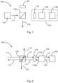
- Fig. 1 shows the structural design of a modulator unit 100.
- the modulator unit 100 includes a light source 110, a beam splitter 120, a beam absorber 125, a polarization component separator 170, a (polarization-dependent or polarization-independent) phase modulator in the form of an electro-optical modulator, EOM, 130, and a reflector in the form of a Faraday mirror 140.
- EOM 130, the Faraday mirror 140, and the polarization component separator 170 may collectively be referred to as polarization modulator 105.
- polarization modulator 105 may collectively be referred to as polarization modulator 105.
- the light source 110 which is, for example, a laser, emits a pulsed optical signal in the form of the input signal 111.
- This input signal is fed to the other components and the phase of its polarization components is phase-modulated in order to transmit information in the polarization of the optical signal resulting from the superimposed polarization components.
- the information to be transmitted is modulated on the output signal 118 in the polarization of the optical signal.
- Fig. 2 The path of the optical signal through the modulator unit 100 is described. Reference is made to the state of the optical signal at different times or at different points in the modulator unit 100.
- the input signal 111 hits the beam splitter 120.
- the beam splitter 120 is designed as a non-polarizing beam splitter. A portion of the input signal 111 is directed toward the beam absorber 125 as the first portion 112 of the split input signal, and another portion of the input signal 111 passes through the beam splitter 120 as the second portion 113 of the split input signal towards the polarization component separator 170 and the EOM 130.
- the polarization component separator 170 has the function of splitting an optical signal 113 (or in the opposite direction the optical signal 115A) into its polarization components and transmitting them over two different optical paths (see Fig. 3 ) with different signal propagation times, whereby a relative time delay between the two polarization components is introduced (in the first pass through the polarization component separator) or eliminated (in the second pass through the polarization component separator).
- the optical signal 113A thus contains two polarization components on its way to the EOM 130 that are offset in time from one another. From a physical perspective, two signals are transmitted here, each polarization component representing an optical signal.
- the first polarization component contains light with a first polarization direction (e.g., horizontal polarization), and the second polarization component contains light with a second polarization direction different from the first polarization direction (e.g., vertical polarization).
- the EOM 130 now modulates a polarization component of the optical signal 113A by changing the phase of this polarization component of the signal 113A.
- the optical signal 114 is present such that the first polarization component with the first polarization direction is phase-modulated and the second polarization component with the second polarization direction is not modulated (if the EOM is a polarization-dependent phase modulator).
- the Faraday mirror 140 retroreflects the signal 114 and changes the polarization of both polarization components by 90° each, so that the optical signal 114 with its two polarization components is reflected as a mirrored signal 115 to the EOM 130.
- the optical signal 115 therefore also contains two polarization components that are delayed relative to one another.
- the optical signals 113, 113A, 114 contain a first polarization component with a first polarization direction and a second polarization component with a second polarization direction.
- the polarization directions of the two polarization components are changed: in the optical signal 115, the first polarization component contains light with the second polarization direction, and the second polarization component contains light with the first polarization direction.
- the first and second polarization components pass through the EOM 130.
- the second polarization component is modulated because the second polarization component contains the light with the first polarization direction, whereas the first polarization component, which contains light with the second polarization direction, is not modulated.
- the horizontally polarized pulse of the optical signal was modulated during the first pass between signals 113 and 114 through the EOM, then during the second pass this modulation is now contained in the vertically polarized pulse of the optical signal 115 because the Faraday mirror 140 has changed the polarization by 90°. If the optical signal 115 now passes through the EOM 130 again during the second pass, the now horizontally polarized pulse (corresponding to the vertically polarized pulse during the first pass, which did not undergo any phase change during the first pass) is phase-changed.
- the optical length between the EOM 130 and the Faraday mirror 140 is dimensioned such that an optical signal on the second pass does not overlap an optical signal on the first pass within the EOM while one of these optical signals is being modulated.
- polarization components of different polarization directions may overlap because only one polarization direction is modulated.
- the length of the optical path between the EOM and the Faraday mirror is dimensioned such that a polarization component on the second pass does not overlap a polarization component on the first pass.
- the length of the optical path is matched to the duration of a light pulse from the light source 110 and the transmission rate.
- the EOM applies a phase to both polarization components of the optical signal on the same optical path.
- the polarization of the resulting optical signal 116 can be varied.
- the optical signal 116 is now phase-modulated in both polarization components. The superposition of these two modulations results in the polarization of the optical signal 116, which contains the information to be transmitted.
- the optical signal 116 now hits the beam splitter 120 again.
- a portion 117 of the optical signal passes through the beam splitter, and another portion 118 is deflected in a different direction and corresponds to the output signal to be transmitted, the polarization of which contains the information to be transmitted.
- the output signal passes through the beam splitter and the deflected signal is discarded.
- Fig. 3 shows a schematic diagram of a polarization component separator 170.
- the polarization component separator 170 is designed to separate differently polarized components of an optical signal from one another and transmit them over different optical paths.
- the polarization component separator 170 operates bidirectionally, meaning that optical signals can pass through the polarization component separator 170 in two directions (i.e., from left to right, signals 113 and 113A, and from right to left, signals 115A, 116), with the polarization component separator 170 performing the same function for optical signals in both directions.
- the following describes the path of the optical signal 113 through the polarization component separator 170. This path is referred to as the first pass. The same applies to the path of the optical signal 115A through the polarization component separator 170, whereby this path is referred to as the second pass.
- an optical signal 113 containing two polarization components impinges on the first interface 171 of the first polarizing beam splitter 172.
- the first polarizing beam splitter 172 separates the two polarization components from each other.
- An optical signal 113 fed into the polarizing beam splitter 172 is split and results in two optical polarization components, which are output at the second interface 173 of the first polarizing beam splitter 172 and each guided via one of the two separate optical sections 174, 176.
- the first polarization component is guided, for example, via the first optical section 174 and the second polarization component is guided via the second optical section 176.
- the optical sections 174, 176 have different signal propagation times for optical signals or different optical path lengths. Starting from an identical or While the propagation speed of optical signals over the two optical sections 174, 176 is almost identical, the propagation time of optical signals over the optical sections 174, 176 is different. For example, the second optical section 176 is longer than the first optical section 174.
- the two polarization components into which the optical signal 113 was split experience a relative temporal offset through the first and second optical sections 174, 176.
- the temporal offset between the two polarization components is dimensioned such that there is no temporal overlap between the two polarization components after they are passed back onto a common optical path on the output side, i.e., at the second polarizing beam splitter 178.
- the first polarization component arrives at the second polarizing beam splitter 178 via the first optical section 174 and the second polarization component via the second optical section 176 in such a way that the second polarization component only arrives after the first polarization component has passed the second interface 179 of the second polarizing beam splitter 178.
- the two polarization components reach the second interface 179 of the second polarizing beam splitter 178 via the first and second optical sections 174, 176.
- the two polarization components are combined by the second polarizing beam splitter and output at the first interface 177 via a common optical path in the direction of the phase modulator 130.
- This function which was described for the optical signal 113 by the polarization component separator 170, also applies analogously to the optical signal 115A, which Polarization component separator 170 in the opposite direction (compared to the optical signal 113).
- the optical signal 113 is transmitted as a pulsed signal.
- the light pulses have a specific pulse duration with a start and end time. Between the light pulses, there is a predetermined time, depending on the transmission frequency, during which no optical signal is transmitted. Thus, the individual polarization components are also transmitted as light pulses. After the polarization components have passed through the optical sections 174, 176, there is a time offset between the light pulses of one polarization component and the light pulses of the second polarization component.
- the light pulse of the second polarization component, which is transmitted via the second optical path 176, can be referred to as a delayed light pulse
- the light pulse of the first polarization component, which is transmitted via the first optical path 174 can be referred to as a non-delayed light pulse.
- the time offset between the light pulses of the two polarization components is preferably configured such that the start time of the delayed light pulse is later than the end time of the non-delayed light pulse, and there is a time period between the start time of the delayed light pulse and the end time of the non-delayed light pulse that is, for example, greater than 0 seconds.
- the temporal offset is defined by the respective propagation time of an optical signal across the two optical sections 174, 176.
- the temporal offset between the two polarization components can be influenced by selecting the signal propagation times or optical lengths of the two optical sections 174, 176 accordingly.
- the optical sections 174, 176 can be implemented as fiber-based or free-beam optical fibers.
- the optical fibers are polarization-maintaining optical fibers.
- the optical fiber of the first optical section 174 has a first length that differs from a second length of the optical fiber of the second optical section 176. This difference in length between the optical sections 174, 176 is Fig. 3 shown as a loop in the second optical section 176. In other words, the fiber of the second optical section 176 is longer than the fiber of the first optical section 174.
- the optical sections 174, 176 can also be implemented as a free beam.
- an optical beam is guided over a predetermined distance, for example, using mirrors or other optical deflection elements.
- the length of the optical sections can be influenced by the position of the mirrors.
- the function of the polarization component separator 170 can be described as follows: an optical signal with two polarization components is split into these two polarization components. The polarization components are transmitted over separate optical sections. One polarization component experiences a delay on its optical section. This delay can arise from different optical lengths of the optical sections. However, it is also conceivable to integrate an optical delay element into an optical section in order to increase the propagation time of one polarization component compared to the propagation time of the other polarization component. The polarization components thus provided with a temporal offset are subsequently recombined onto a common optical path and transmitted. One polarization component can now be modulated.
- the reflector reflects the polarization components back to the phase modulator, thereby changing their polarization direction.
- the phase modulator then modulates the other polarization component.
- both polarization components have experienced modulation.
- the polarization components strike the second polarizing beam splitter 178.
- the second polarizing beam splitter 178 functions in such a way that the polarization components are guided via the first optical section 174 or the second optical section 176, depending on their polarization direction.
- the polarization components pass through the other optical section during the second pass (from right to left, optical beams 115A, 116). This means that the polarization component that passed through the first optical section 174 during the first pass is transmitted over the second optical section 176 during the second pass, and vice versa. During the second pass, the polarization component that was not delayed during the first pass is delayed, and vice versa.
- both polarization components are modulated and no longer have a temporal offset from one another. Each polarization component experiences the same degree of relative temporal delay in one direction by the polarization component separator 170, so that in the optical signal 116 the two polarization components coincide again in time.
- the polarization-dependent phase modulator 130 applies phase modulation to a first polarization component.
- the other (second) polarization component is not modulated.
- the polarization-dependent phase modulator 130 applies phase modulation to the second polarization component.
- the first polarization component is not modulated.
- the phase modulator 130 is preferably controlled such that it applies phase modulation only when a first polarization component with a corresponding polarization direction passes through the phase modulator. If a second polarization component with a different polarization direction passes through the phase modulator, the phase modulator does not apply any modulation. This ensures that the second polarization component is neither intentionally nor unintentionally subjected to phase modulation, e.g., due to parasitic effects. This has the advantage that the device described here can perform highly precise phase modulation with a low error rate.
- the phase modulator 130 After the phase modulator 130 has applied phase modulation to the first polarization component in this way, the two polarization components reach the reflector 140.
- the reflector 140 reflects the two polarization components, changing their polarization directions in the process, so that during the second pass (from right to left, i.e., signal direction 115, 115A, 116), the first polarization component adopts the polarization direction of the second polarization component of the first pass, and the second polarization component adopts the polarization direction of the first polarization component of the first pass.
- the phase modulator 130 now applies phase modulation to the second polarization component without applying any modulation when the first polarization component is transmitted through the phase modulator 130.
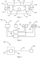
- Fig. 4 shows how the components of the modulator unit 100 are controlled in order to incorporate the information to be transmitted into the polarization of the optical signal.
- the modulator unit 100 includes a power supply 160 and a control unit 150. Both the power supply 160 and the control unit 150 are connected to the light source 110, the EOM 130, and the Faraday mirror 140. However, the control unit 150 can also be directly connected to the power supply 160 in order to specify an electrical voltage output by the power supply 160 at the respective terminal.
- the power supply 160 supplies the light source 110 with electrical energy so that the light source generates the optical signal, which acts as the input signal.
- the power supply 160 also supplies the EOM 130 with electrical energy, for example, an electrical voltage applied to a crystal 135. This electrical voltage influences the crystal 135 such that the phase of a polarization component of a passing optical signal is changed. For example, variations in the electrical voltage can change the phase to varying degrees.
- the control unit 150 and the power supply 160 control the EOM such that it acts on the polarization component passing through the EOM in the desired manner during the first and second pass of the optical signal and changes the phase of the influenced polarization component accordingly and as desired.
- the control unit and the power supply must switch quickly enough and control the EOM.
- the polarization of a passing optical signal is changed in the Faraday rotator 143, in this example by 45°.
- the optical signal then hits the mirror 145, is reflected by it and passes through the Faraday rotator 143 again. Now the polarization of the optical signal is changed again by 45° in the same direction, so that the polarization of the Faraday mirror and the polarization of the optical signal output by the Faraday mirror differ by 90°.
- the control unit 150 is configured to control the power supply 160 and/or each of the components 110, 130, 140 such that these components are supplied with the energy required for their function.
- the control unit 150 can send control commands to the components 110, 130, 140 and/or control commands to the power supply 160.
- the polarization component separator 170 is arranged between the light source 110 and the phase modulator 130.
- the polarization component modulator can be a passive component that does not require separate control by the control unit 150.
- the polarization component separator 170 can be an active component that is supplied with power by the power supply 160 and controlled by the control unit 150.
- the polarization component separator 170 can be configured to vary the signal propagation time of a polarization component, and the control unit 150 can be configured to specify the extent of the time delay of a polarization component by the polarization component separator 170.
- Fig. 5 shows an optical signal transmission path 200.
- a modulator unit 100 acts as a signal source or transmitter.
- the modulator unit 100 modulates the polarization of an optical signal as described above and transmits the modulated optical signal via a transmission path 210.
- the transmission path 210 is, for example, a wireless optical path.
- the modulated optical signal is received and processed by a remote station, the receiver 220.
- the modulator unit 100 can be installed on board a satellite or on the Earth's surface.
- the receiver 220 may be located on the Earth's surface or on board another satellite.
Landscapes
- Physics & Mathematics (AREA)
- Nonlinear Science (AREA)
- General Physics & Mathematics (AREA)
- Optics & Photonics (AREA)
- Engineering & Computer Science (AREA)
- Electromagnetism (AREA)
- Computer Networks & Wireless Communication (AREA)
- Signal Processing (AREA)
- Chemical & Material Sciences (AREA)
- Ceramic Engineering (AREA)
- Crystallography & Structural Chemistry (AREA)
- Optical Communication System (AREA)
Description
- Die vorliegende Beschreibung betrifft optische Signalerzeugung und Signalübertragung, insbesondere die Übertragung von Informationen mittels Polarisationsmodulation. Im Speziellen betrifft die Beschreibung eine Modulatoreinheit zum Modulieren der Polarisation eines optischen Signals, eine optische Signalübertragungsstrecke mit einer solchen Modulatoreinheit, und ein System mit einer solchen Modulatoreinheit, beispielsweise in Form eines Satelliten.
- Informationen können mit technischen Mitteln übertragen werden, indem eine Informationseinheit einem bestimmten Zustand eines Trägersignals zugewiesen wird. Das Trägersignal ist üblicherweise eine elektromagnetische Welle aus einem spezifischen spektralen Bereich. Um nun eine Information auf das Trägersignal aufzuprägen, wird eine Eigenschaft des Trägersignals geändert. Die Änderung an sich oder der Zustand des Trägersignals nach der Änderung entsprechen dabei der zu übertragenden Information. Üblicherweise wird das Trägersignal in zeitlichen Abständen geändert, um hierdurch mehrere Informationseinheiten zu übertragen.
- Als Informationsträger kommen je nach Trägersignal verschiedene physikalische Merkmale des Trägersignals in Frage, beispielsweise: die Amplitude, die Frequenz, die Phase und/oder die Polarisation. Wird eines dieser Merkmale über der Zeit verändert, so wird dieser Vorgang als Modulation bezeichnet.
- Auf dem Signalverarbeitungspfad kommen verschiedene technische Komponenten zum Einsatz, um das Trägersignal zu bearbeiten und die gewünschte Information in das Trägersignal einzubringen, bevor das Trägersignal über die Übertragungsstrecke (leitungsgebunden oder leitungslos) übertragen wird.
- Die bei der Vorbereitung und Bearbeitung des Trägersignals verwendeten Komponenten dienen dazu, das Trägersignal entsprechend zu modulieren, damit die zu übertragende Information richtig auf das Trägersignal aufgebracht wird und mit möglichst wenig Störungen und Verlusten über die Übertragungsstrecke übertragen wird.
- Nun kann es aber vorkommen, dass neben der gewollten Modulation (Veränderung des Trägersignals) auch ungewollte Veränderungen des Trägersignals erfolgen, beispielsweise durch parasitäre Effekte oder andere ungewollte Eigenschaften der in die Vorbereitung des Trägersignals involvierten Komponenten. In dem Fall ist es bei einem Empfänger des Trägersignals nicht immer erkennbar, welche Veränderung des Trägersignals auf der gewollten Modulation basiert und welche Veränderung von ungewollten Effekten hervorgerufen wurde. Dadurch kann die Güte des Signals negativ beeinflusst werden.
- Jedes der folgenden Nicht-Patentdokumente offenbart einen Polarisationsmodulator auf der Grundlage einer Sagnac-Schleife mit einem Phasenmodulator und einem Faraday-Rotator-Spiegel:
X. LIU, C. LIAO ET AL.: "Polarization coding and decoding by phase modulation in polarizing Sagnac interferometers", PROC. SPIE, Bd. 6827, 26. November 2007 (2007-11-26), Seiten 682701-1-682701-1 - COSTANTINO AGNESI ET AL: "All-fiber self-compensating polarization encoder for Quantum Key Distribution", ARXIV.ORG, CORNELL UNIVERSITY LIBRARY, 201 OLIN LIBRARY CORNELL UNIVERSITY ITHACA, NY 14853, 2. März 2019 (2019-03-02)
- Ausgehend davon kann es als Aufgabe betrachtet werden, den Einfluss von ungewollten Effekten einer Modulatoreinheit auf ein zur Übertragung moduliertes Trägersignal zu reduzieren oder zu eliminieren. Es kann insbesondere als Aufgabe betrachtet werden, Polarisationsfehler bei einem polarisationsmodulierten optischen Signal zu vermeiden.
- Diese Aufgabe wird gelöst durch den Gegenstand des unabhängigen Anspruchs.
- Weitere Ausführungsformen ergeben sich aus den abhängigen Ansprüchen sowie aus der folgenden Beschreibung.
- Gemäß einem Aspekt ist eine Modulatoreinheit zum Modulieren der Polarisation eines optischen Signals angegeben. Die Modulatoreinheit weist eine Lichtquelle, einen Polarisationskomponentenseparator, einen Phasenmodulator (der insbesondere ein polarisationsabhängiger Phasenmodulator ist, aber auch ein polarisationsunabhängiger Phasenmodulator sein kann), und einen Reflektor auf. Die Lichtquelle ist ausgestaltet, ein optisches Signal auszugeben und als Eingangssignal in Richtung des Polarisationskomponentenseparators zu emittieren, wobei das optische Signal eine erste Polarisationskomponente mit einer ersten Polarisationsrichtung und eine zweite Polarisationskomponente mit einer zweiten Polarisationsrichtung enthält. Der Polarisationskomponentenseparator ist ausgestaltet, die erste Polarisationskomponente von der zweiten Polarisationskomponente zu separieren und die erste Polarisationskomponente über eine erste optische Teilstrecke und die zweite Polarisationskomponente über eine zweite optische Teilstrecke zu übertragen. Der ersten optischen Teilstrecke ist eine erste Signallaufzeit zugeordnet und der zweiten optischen Teilstrecke ist eine zweite Signallaufzeit zugeordnet, wobei die erste Signallaufzeit sich von der zweiten Signallaufzeit unterscheidet, d.h., dass die erste Signallaufzeit größer oder kleiner als die zweite Signallaufzeit ist. Der Polarisationskomponentenseparator ist ausgestaltet, als Ergebnis des Unterschieds zwischen der ersten Signallaufzeit und der zweiten Signallaufzeit, einen zeitlichen Versatz zwischen die erste Polarisationskomponente und die zweite Polarisationskomponente einzubringen und die erste Polarisationskomponente und die zweite Polarisationskomponente auf einem gemeinsamen optischen Pfad zu dem Phasenmodulator zu übertragen. Der Phasenmodulator ist ausgestaltet, eine erste Phase der ersten Polarisationskomponente in der ersten Polarisationsrichtung zu modulieren und die modulierte erste Polarisationskomponente an den Reflektor weiterzuleiten. Der Reflektor ist ausgestaltet, sowohl die erste Polarisationskomponente als auch die zweite Polarisationskomponente in Richtung des Phasenmodulators zu retroreflektieren und dabei die jeweilige Polarisation zu verändern (beispielsweise um 90°), so dass die erste Polarisationskomponente mit der ersten Polarisationsrichtung die zweite Polarisationsrichtung erhält und die zweite Polarisationskomponente mit der zweiten Polarisationsrichtung die erste Polarisationsrichtung erhält. Der Phasenmodulator ist ausgestaltet, eine zweite Phase der retroreflektierten zweiten Polarisationskomponente in der ersten Polarisationsrichtung zu modulieren und die retroreflektierte erste Polarisationskomponente und die retroreflektierte zweite Polarisationskomponente an den Polarisationskomponentenseparator zu übertragen. Der Polarisationskomponentenseparator ist ausgestaltet, den zeitlichen Versatz zwischen der retroreflektierten ersten Polarisationskomponente und der retroreflektierten zweiten Polarisationskomponente zu eliminieren und die retroreflektierte erste Polarisationskomponente und die retroreflektierte zweite Polarisationskomponente ohne zeitlichen Versatz über einen gemeinsamen optischen Pfad auszugeben. Die Modulatoreinheit ist ausgestaltet, das so modulierte optische Signal als polarisationsmoduliertes Ausgangssignal auszugeben.
- Die erste Polarisationskomponente und die zweite Polarisationskomponente sind beim ersten Passieren des Phasenmodulators zeitlich voneinander getrennt. Daher kann die zweite Polarisationskomponente beim ersten Passieren des Phasenmodulators moduliert werden oder nicht moduliert werden. Anschließend wird dann sowohl die erste Polarisationskomponente als auch die zweite Polarisationskomponente an den Reflektor weitergeleitet.
- Das von der Lichtquelle erzeugte und ausgegebene optische Signal stellt grundsätzlich eine Überlagerung aus zwei orthogonalen Polarisationskomponenten dar. Der Phasenmodulator ist ausgestaltet, jeweils eine gewünschte Phase auf beide Polarisationskomponenten aufzubringen.
- Grundsätzlich kann die Lichtquelle ein Lichtemitter sein (beispielsweise ein Laser) oder der Ausgang eines lichtführenden Elements. In einem Ausführungsbeispiel durchläuft das optische Signal denselben optischen Pfad der Modulatoreinheit zweimal in entgegengesetzte Richtungen. Beim ersten Durchlauf läuft das optische Signal bzw. seine Polarisationskomponenten von der Lichtquelle durch den Polarisationskomponentenseparator und den Phasenmodulator zu dem Reflektor. Der Reflektor retroreflektiert das optische Signal und dreht die Phase des optischen Signals dabei um 90° (entweder +90° oder -90°). Beispielsweise ist der Reflektor als Faraday-Spiegel implementiert, der ein auf dem Faraday-Effekt beruhender Retroreflektor ist, der einen Kristall enthält, an welchem ein Magnetfeld anliegt und der die Polarisation in Abhängigkeit von der Ausbreitungsrichtung des Magnetfeldes dreht. Wenn beispielsweise horizontal polarisiertes Licht auf den Reflektor trifft, wird dies als vertikal polarisiertes Licht retroreflektiert. Es handelt sich also bei dem Reflektor um die Kombination aus einem Faraday-Rotator und einem Spiegel. Der Faraday-Rotator wird zunächst von dem optischen Signal passiert und die Polarisation des Lichts wird dabei um 45° (+45° oder -45°) gedreht. Dann wird das optische Signal gespiegelt und passiert erneut den Faraday-Rotator, wobei seine Polarisation um weitere 45° (in dieselbe Richtung wie im ersten Schritt) gedreht wird. In Summe unterscheidet sich dann die Polarisation des retroreflektierten Lichts von der Polarisation des einfallenden Lichts um 90°.
- Gerade weil das optische Signal bzw. seine Polarisationskomponenten den Phasenmodulator mit getauschten Polarisationsrichtungen und zeitlichem Versatz zwischen den Polarisationskomponenten zweimal durchläuft, wirkt der Phasenmodulator zunächst auf die zu modulierende Polarisationskomponente und die zeitlich verzögerte Polarisationskomponente passiert den Phasenmodulator entweder ohne aktiven Einfluss auf deren Phase oder sie kann auch beim ersten Durchlauf moduliert werden. Bei einem polarisationsabhängigen Phasenmodulator wird die zweite Polarisationskomponente zunächst nicht moduliert (weil die zweite Polarisationskomponente eine andere Polarisationsrichtung hat als die erste Polarisationskomponente), bei einem polarisationsunabhängigen Phasenmodulator hingegen kann auch die zweite Polarisationskomponente beim ersten Durchlauf moduliert werden.
- Im Folgenden werden einige Beispiele mit Bezugnahme auf einen polarisationsabhängigen Phasenmodulator beschrieben. Es sollte jedoch verstanden werden, dass das hier beschriebene Prinzip auch mit einem polarisationsunabhängigen Phasenmodulator implementiert werden kann.
- Im Ergebnis werden parasitäre Einflüsse der Modulatoreinheit auf die Polarisationskomponenten des optischen Signals und Fehlerphasen eliminiert.
- Beim ersten Durchlauf wird beispielsweise die Komponente des optischen Signals mit horizontaler Polarisation (für das Beispiel als erste Polarisationsrichtung angenommen) moduliert (es wird eine erste Phase auf diese Komponente moduliert) und die Komponente mit vertikaler Polarisation (für das Beispiel als zweite Polarisationsrichtung angenommen) passiert den Phasenmodulator, ohne dass Veränderungen an der Phase dieser Komponente vorgenommen werden. Nun wird das optische Signal von dem Reflektor retroreflektiert und die Polarisation um 90° gedreht, die Komponente mit horizontaler Polarisation ist nun vertikal polarisiert, die Komponente mit vertikaler Polarisation ist nun horizontal polarisiert. Beim zweiten Durchlauf durchläuft das optische Signal mit seinen Polarisationskomponenten erneut den Phasenmodulator, und nun wird die (jetzt) horizontal polarisierte Komponente (welche der vertikal polarisierten Komponente des ersten Durchlaufs entspricht) in seiner Phase moduliert und die (jetzt) vertikal polarisierte Komponente passiert den Phasenmodulator ohne weitere Änderung seiner Phase. Dies bedeutet, dass der Phasenmodulator nur eine einzelne Modulationsachse hat, welche für den ersten und zweiten Durchlauf von optischen Signalen gleichbleibt, also auf dieselbe Polarisationsrichtung wirkt.
- Wird beim ersten Durchlauf eine Fehlerphase (oder Fehlphasenverschiebung) in das optische Signal eingebracht, indem beispielsweise die Phase der horizontal polarisierten Komponente auf andere Weise als die Phase der vertikal polarisierten Komponente parasitär beeinflusst wird, so hebt sich diese Fehlerphase beim zweiten Durchlauf auf, weil das optische Signal mit einer um 90° gedrehten Polarisation denselben optischen Pfad durchläuft und die gleiche Fehlerphase nun auf die jeweils andere Polarisationsachse aufgetragen wird. Hierdurch werden alle relativen Phasenfehler auf gleiche Weise in beide Polarisationsachsen eingebracht. Außerdem wird durch die zeitliche Verzögerung zwischen den beiden Polarisationskomponenten ein parasitärer Einfluss auf die Polarisationskomponente, die außerhalb der Polarisationsachse des Phasenmodulators liegt, vermieden.
- Die Phase, welche auf die horizontal polarisierte Komponente des zweiten Durchlaufs aufgebracht wird, wird als zweite Phase bezeichnet, weil beim zweiten Durchlauf die erste Phase in der vertikal polarisierten Komponente des optischen Signals enthalten ist und die erste Phase gegenüber der zweiten Phase unterschiedlich sein kann.
- In dem hier wiedergegeben Beispiel wird in einer bestimmten Weise auf horizontal und vertikal polarisierte Komponenten des optischen Signals Bezug genommen, nämlich dass beim ersten und zweiten Durchlauf durch den Phasenmodulator jeweils die horizontal polarisierte Komponente phasenmoduliert wird. Es versteht sich allerdings, dass dieses Beispiel nicht einschränkend ist und der Phasenmodulator statt der horizontal polarisierten Komponente die vertikal polarisierte Komponente oder eine beliebige andere Komponente des optischen Signals phasenmodulieren kann. Entscheidend ist, dass die Polarisationskomponenten zeitlich zueinander versetzt sind und zwischen den beiden Vorgängen, bei denen die Phase einer Polarisationskomponente des optischen Signals moduliert wird, die Polarisation der beiden Polarisationskomponenten um jeweils 90° gedreht wird.
- Im Ergebnis werden bei diesem Aufbau sowohl die vertikal polarisierte Komponente als auch die horizontal polarisierte Komponente des optischen Signals in einer Modulatoreinheit moduliert. Das resultierende optische Signal hat in Summe eine gewünschte Polarisationsmodulation erhalten, indem beim ersten Durchlauf die erste Polarisationskomponente mit einer ersten Polarisationsrichtung und beim zweiten Durchlauf die zweite Polarisationskomponente, welche beim zweiten Durchlauf die erste Polarisationsrichtung hat, in ihrer Phase moduliert werden, wobei jedoch die Polarisation des optischen Signals beim zweiten Durchlauf im Vergleich zum ersten Durchlauf um 90° verändert ist.
- Der hier verwendete Phasenmodulator ist beispielsweise ein phasenverändernder Modulator, welcher auf eine Polarisationskomponente eines optischen Signals wirkt, d.h. dass der Phasenmodulator die Phase zweier orthogonal zueinander stehender Polarisationskomponenten des optischen Lichts verändert. Beispielsweise ist der Phasenmodulator ein elektro-optischer Modulator, EOM. Es ist zu verstehen, dass jegliche Bezugnahme auf einen EOM in dieser Beschreibung lediglich beispielhaft erfolgt und grundsätzlich für einen Phasenmodulator gilt, der polarisationsabhängig oder polarisationsunabhängig sein kann.
- Beispielsweise hat der Phasenmodulator zwei orthogonal zueinander ausgerichtete optische Achsen. Mittels elektrischer Energie, beispielsweise einer angelegten Spannung entlang einer dieser optischen Achsen (das ist die Polarisationsachse), wird deren Brechungsindex modifiziert und es resultiert eine Phasenveränderung der Polarisationskomponente des optischen Signals gegenüber der anderen bzw. orthogonalen optischen Achse.
- Durch die Verwendung eines Faraday-Spiegels ist der Aufbau der Modulatoreinheit sehr platzsparend und kompakt. Ein Phasenmodulator kann sehr schnell geschaltet werden, so dass die hier beschriebene Modulatoreinheit bis in hohe Frequenzbereiche verwendet werden kann, beispielsweise mehrere 10 GHz, wie z.B. bis hin zu 30 bis 40 GHz oder auch höheren Frequenzbereichen.
- Mit der hier beschriebenen Modulatoreinheit lassen sich verschiedene Polarisationszustände eines optischen Signals einstellen. Hierbei können beispielsweise verschiedene diskrete Zustände der Polarisation eingestellt werden, indem die Phase der horizontal polarisierten Polarisationskomponente des optischen Signals mit Bezug zu der Phase der vertikal polarisierten Polarisationskomponente des optischen Signals verändert wird. Die Polarisation des optischen Signals kann aber grundsätzlich beliebig kontinuierlich als Linearkombination der beiden Polarisationskomponenten verändert werden, ohne auf eine beschränkte Anzahl von Polarisationszuständen begrenzt zu sein.
- Der Polarisationskomponentenseparator trägt dazu bei, dass parasitäre Effekte des Phasenmodulators auf eine nicht modulierte Polarisationskomponente verhindert werden. Grundsätzlich kann ein Phasenmodulator parasitäre oder ungewollte Effekte auch auf optische Signale mit einer solchen Polarisationsrichtung haben, welche außerhalb der Polarisationsachse des Phasenmodulators liegen und welche der Phasenmodulator entsprechend prinzipiell unbeeinflusst passieren lassen sollte.
- Somit kann es vorkommen, dass ein polarisationsabhängiger Phasenmodulator, welcher nur horizontal polarisiertes Licht modulieren soll, auch vertikal polarisiertes Licht beeinflusst. Bei Letzterem handelt es sich um einen ungewollten/parasitären Effekt. Dieser Effekt kann jedoch zu Ungenauigkeiten und Fehlern in der Modulation führen. Um diesen Effekt zu eliminieren, wird vorliegend vorgeschlagen, dass ein optisches Signal in Polarisationskomponenten mit unterschiedlicher Polarisationsrichtung aufgeteilt wird, zwischen diese beiden Polarisationskomponenten ein zeitlicher Versatz eingebracht wird, und sie dann nacheinander den Phasenmodulator passieren. Der Phasenmodulator wird so angesteuert, dass er lediglich die Polarisationskomponente moduliert, welche jeweils moduliert werden soll. Beispielsweise wird der Phasenmodulator so angesteuert, dass er eine Modulation aufbringt, wenn horizontal polarisiertes Licht den Phasenmodulator passiert. Wenn hingegen vertikal polarisiertes Licht den Phasenmodulator passiert, ist der Phasenmodulator nicht aktiv, d.h. er wirkt nicht modulierend auf das entsprechende Signal. Auf diese Weise wird verhindert, dass eine ungewollte Modulation oder Verfälschung in die vertikal polarisierte Polarisationskomponente eingebracht wird. Die Polarisationskomponenten sind sowohl in unterschiedliche Richtungen polarisiert und passieren den Phasenmodulator mit zeitlichem Abstand. Der Phasenmodulator wendet eine Modulation nur auf eine Polarisationskomponente an. Wenn die nicht zu modulierende Polarisationskomponente den Phasenmodulator passiert, wird keine Modulation aufgebracht bzw. der Phasenmodulator ist nicht aktiv. Der Reflektor reflektiert die optischen Signale zurück zu dem Phasenmodulator und ändert die Polarisationsrichtung der Polarisationskomponenten. Die erste Polarisationskomponente erhält die zweite Polarisationsrichtung und die zweite Polarisationskomponente erhält die erste Polarisationsrichtung. Beide Polarisationskomponenten passieren erneut den Phasenmodulator. Nun wirkt der Phasenmodulator aber auf die andere Polarisationskomponente, weil sich die jeweilige Polarisationsrichtung geändert hat und der Phasenmodulator seine Polarisationsachse beibehält. Anschließend wird der zeitliche Versatz eliminiert und die beiden Polarisationskomponenten werden über einen gemeinsamen optischen Pfad ausgegeben. Beide Polarisationskomponenten enthalten nun eine gewünschte aufmodulierte Phaseninformation und ein optisches Signal, welches die beiden Polarisationskomponenten enthält, wird ausgegeben.
- In anderen Worten und in einem nicht einschränken Beispiel kann die Arbeitsweise der Modulatoreinheit wie folgt beschrieben werden:
Der Phasenmodulator ist ausgestaltet, bevor die beiden Polarisationskomponenten auf den Reflektor treffen, eine Phasenmodulation ausschließlich auf die erste Polarisationskomponente aufzubringen, und nachdem der Reflektor die beiden Polarisationskomponenten reflektiert, eine Phasenmodulation ausschließlich auf die zweite Polarisationskomponente aufzubringen. Beim ersten Durchlauf, also wenn das optische Signal den Phasenmodulator erstmals passiert, wird von dem Phasenmodulator die erste Polarisationskomponente mit der ersten Polarisationsrichtung (beispielsweise horizontale Polarisationsrichtung) moduliert und die zweite Polarisationskomponente mit der zweiten Polarisationsrichtung (beispielsweise vertikale Polarisationsrichtung) wird unverändert übertragen. Beim zweiten Durchlauf, nachdem der Reflektor die Polarisationskomponenten reflektiert und in ihrer Polarisationsrichtung verändert hat, wird von dem Phasenmodulator die zweite Polarisationskomponente, die nun die erste Polarisationsrichtung hat (in diesem Beispiel horizontale Polarisationsrichtung), moduliert und die zweite Polarisationskomponente, die nun die zweite Polarisationsrichtung hat (in diesem Beispiel vertikale Polarisationsrichtung), wird unverändert übertragen. - Gemäß einer Ausführungsform hat die erste optische Teilstrecke eine erste optische Pfadlänge und die zweite optische Teilstrecke hat eine zweite optische Pfadlänge, wobei sich die erste optische Pfadlänge von der zweiten optischen Pfadlänge unterscheidet.
- Die zeitliche Verzögerung zwischen den beiden Polarisationskomponenten kann grundsätzlich auf unterschiedliche Weisen eingebracht werden. Ganz allgemein erfolgt das durch eine unterschiedliche Signallaufzeit über die beiden optischen Teilstrecken. Diese unterschiedliche Signallaufzeit kann beispielsweise eingebracht werden, indem ein Verzögerungsglied verwendet wird. Sie kann aber auch eingebracht werden, indem die optischen Teilstrecken physikalisch unterschiedlich ausgestaltet sind, beispielsweise eine unterschiedliche optische Pfadlänge haben. Für eine fasergebundene optische Teilstrecke können unterschiedlich lange Fasern verwendet werden. Es ist auch denkbar, dass für beide Polarisationskomponenten eine einzelne polarisationserhaltende optische Faser benutzt wird, unter der Voraussetzung, dass diese optische Faser unterschiedliche Brechungsindizes auf den verschiedenen Polarisationsachsen hat, was für die zeitliche Verzögerung sorgt. Bei einem Freistrahl können die Elemente, welche für die Übertragung des optischen Freistrahls verwendet werden, in unterschiedlichen Abständen zueinander positioniert werden, um eine unterschiedliche optische Laufzeit der optischen Signale über die optischen Teilstrecken zu erreichen.
- Gemäß einer weiteren Ausführungsform weist der Polarisationskomponentenseparator einen ersten polarisierenden Strahlteiler und einen zweiten polarisierenden Strahlteiler auf, wobei die erste optische Teilstrecke und die zweite optische Teilstrecke zwischen dem ersten polarisierenden Strahlteiler und dem zweiten polarisierenden Strahlteiler angeordnet sind.
- Jeder polarisierende Strahlteiler hat eine erste Schnittstelle und eine zweite Schnittstelle. Optische Signale, die an der ersten Schnittstelle auf den polarisierenden Strahlteiler treffen, werden in Abhängigkeit von ihrer Polarisationsrichtung in Polarisationskomponenten aufgeteilt, welche dann an der zweiten Schnittstelle über die erste optische Teilstrecke oder über die zweite optische Teilstrecke gelenkt werden, so dass Polarisationskomponenten mit unterschiedlichen Polarisationsrichtungen unterschiedliche optische Teilstrecken durchlaufen. Umgekehrt werden optische Signale, die mit entsprechender Polarisationsrichtung über die beiden optischen Teilstrecken an der zweiten Schnittstelle auf den entsprechenden polarisierenden Strahlteiler treffen, zusammengeführt und über einen gemeinsamen optischen Pfad an der ersten Schnittstelle ausgegeben.
- Ein optisches Signal von der Lichtquelle trifft in dem Polarisationskomponentenseparator zunächst auf den ersten polarisierenden Strahlteiler. Dieser erste polarisierende Strahlteiler teilt das optische Signal in die erste Polarisationskomponente mit erster Polarisationsrichtung und die zweite Polarisationskomponente mit zweiter Polarisationsrichtung auf. Die erste Polarisationskomponente wird über eine optische Teilstrecke geleitet, beispielsweise über die erste optische Teilstrecke. Die zweite Polarisationskomponente wird über die andere optische Teilstrecke geleitet, beispielsweise über die zweite optische Teilstrecke. Auf Grund der unterschiedlichen Signallaufzeiten über die optischen Teilstrecken wird ein relativer zeitlicher Versatz zwischen die beiden Polarisationskomponenten eingebracht. Nun erreichen die beiden Polarisationskomponenten den zweiten Strahlteiler, welcher die eingehenden Polarisationskomponenten wieder zusammenführt und diese über einen gemeinsamen optischen Pfad zu dem Phasenmodulator weitergibt. Die Polarisationskomponenten passieren den Phasenmodulator mit zeitlichem Abstand nacheinander. Eine Polarisationskomponente wird moduliert, die andere wird unverändert übertragen. Die Polarisationskomponenten treffen anschließend auf den Reflektor, welcher die Polarisationskomponenten reflektiert und dabei ihre Polarisationsrichtung verändert. Beispielsweise wird ein optisches Signal mit horizontaler Polarisationsrichtung so verändert, dass es vertikal polarisiert ist, und umgekehrt. Der Reflektor versieht die erste Polarisationskomponente mit der zweiten Polarisationsrichtung und die zweite Polarisationskomponente mit der ersten Polarisationsrichtung. Auf dem Rückweg moduliert der Phasenmodulator nun die zweite Polarisationskomponente und lässt die erste Polarisationskomponente unverändert passieren. Noch liegt ein zeitlicher Versatz zwischen den beiden Polarisationskomponenten. Dieser zeitliche Versatz wird eliminiert, wenn die Polarisationskomponenten den Polarisationskomponentenseparator zum zweiten Mal und in die entgegengesetzte Richtung durchlaufen. Die Polarisationskomponenten treffen auf den zweiten polarisierenden Strahlteiler. Dieser leitet die Polarisationskomponenten, die nun veränderte Polarisationsrichtungen haben, so über die optischen Teilstrecken, dass die Polarisationskomponenten nun diejenige optische Teilstrecke durchlaufen, welche sie auf dem Weg zu dem Phasenmodulator nicht durchlaufen haben. Beim ersten Durchlauf wird beispielsweise die erste Polarisationskomponente zeitlich verzögert und beim zweiten Durchlauf wird die zweite Polarisationskomponente zeitlich verzögert. Weil die Polarisationskomponenten den Polarisationskomponentenseparator in entgegengesetzte Richtungen durchlaufen, werden sie jeweils mit derselben zeitlichen Verzögerung beaufschlagt. Nachdem die Polarisationskomponenten den Polarisationskomponentenseparator zweimal und in entgegengesetzte Richtung durchlaufen haben, ist der relative zeitliche Versatz eliminiert.
- Zusammengefasst: um die Polarisationskomponenten zu modulieren, werden die Polarisationskomponenten eines optischen Signals zunächst getrennt und ein zeitlicher Versatz zwischen die Polarisationskomponenten eingebracht. Die Polarisationskomponenten durchlaufen zweimal und mit jeweils veränderten Polarisationsrichtungen den Phasenmodulator. Beim ersten Durchlauf wird die erste Polarisationskomponente moduliert, beim zweiten Durchlauf wird die zweite Polarisationskomponente moduliert. Dann wird der zeitliche Versatz eliminiert und die beiden Polarisationskomponenten zusammengeführt, um dann als phasenmoduliertes optisches Signal ausgegeben zu werden.
- Gemäß einer weiteren Ausführungsform weist der Phasenmodulator einen Kristall auf, welcher ausgestaltet ist, mit einer elektrischen Spannung beaufschlagt zu werden und dabei seinen Brechungsindex zu verändern, wodurch die Phase der ersten Polarisationskomponente und/oder der zweiten Polarisationskomponente des optischen Signals verändert wird. Der Brechungsindex kann aber auch verändert werden, indem eine mechanische Spannung beaufschlagt wird.
- Der Phasenmodulator kann beispielsweise ein doppelbrechendes Medium enthalten, welches bei Anlegen einer Spannung die Phase eines durch das optische Medium passierenden optischen Signals verändert.
- Gemäß einer weiteren Ausführungsform ist die Modulatoreinheit ausgestaltet, die an dem Kristall anliegende elektrische Spannung über der Zeit zu variieren.
- Beispielsweise enthält die Modulatoreinheit eine Energieversorgung, welche eine vorgebbare elektrische Spannung bereitstellt. Eine Steuereinheit steuert die Energieversorgung an, damit letztere eine gewünschte elektrische Spannung an den Phasenmodulator bereitstellt. Durch die über der Zeit variierende elektrische Spannung an dem Phasenmodulator wird die Phase zwischen unterschiedlich polarisierten Komponenten des optischen Signals verändert.
- Gemäß einer weiteren Ausführungsform unterscheidet sich ein Betrag der ersten Phase der ersten Polarisationskomponente des Eingangssignals in der ersten Polarisationsrichtung von einem Betrag der zweiten Phase der zweiten Polarisationskomponente des retroreflektierten optischen Signals in der ersten Polarisationsrichtung.
- In anderen Worten bedeutet dies, dass der Phasenmodulator beim ersten Durchlauf eine andere Phase auf die horizontal polarisierte Komponente des optischen Signals moduliert als beim zweiten Durchlauf auf die dann horizontal polarisierte Komponente des retroreflektierten Signals. Dadurch verändert sich die Polarisation des Ausgangssignals der Modulatoreinheit.
- Gemäß einer weiteren Ausführungsform ist der Phasenmodulator ausgestaltet, einen Unterschied zwischen der ersten Phase und der zweiten Phase über der Zeit zu verändern.
- Indem der Phasenmodulator den Unterschied der Phasen im ersten Durchlauf und im zweiten Durchlauf über der Zeit verändert, wird die Polarisation des Ausgangssignals ebenfalls über der Zeit verändert.
- Insgesamt ist die Polarisation des Ausgangssignals der Modulatoreinheit frei einstellbar zwischen zwei linearen Polarisationen (diagonal/antidiagonal, oder mit Verwendung einer zusätzlichen Wellenplatte am Ausgang des Polarisationsmodulators auch horizontal, vertikal) und zwei zirkularen Polarisationen (Z+ und Z-). Die Polarisation kann aber auch kontinuierlich auf sämtliche zwischen den diskreten Zuständen liegenden elliptischen Zustände eingestellt werden.
- Gemäß einer weiteren Ausführungsform ist die Lichtquelle ausgestaltet, Licht mit einer wohldefinierten optischen Mode zu emittieren oder auszugeben. In dem vorliegenden Zusammenhang sind die Polarisations- und Kohärenzeigenschaften des optischen Signals von Bedeutung. Beispielsweise ist die Lichtquelle ein Laser.
- Laser zeichnen sich dadurch aus, dass sie optische Signale mit einer wohldefinierten Polarisation emittieren können. Damit eignen sie sich insbesondere für Anwendungen wie hier beschrieben.
- Gemäß einer weiteren Ausführungsform ist die Modulatoreinheit ausgestaltet, die Lichtquelle so anzusteuern, dass die Lichtquelle gepulste optische Signale emittiert.
- Ein Lichtpuls passiert den Phasenmodulator und eine erste Polarisationskomponente wird in ihrer Phase moduliert. Sodann wird der Lichtpuls weiter zu dem Reflektor geleitet, dort wird die Polarisation des Lichtpulses geändert und der Lichtpuls zurück zu dem Phasenmodulator reflektiert. Beim zweiten Durchlauf moduliert der Phasenmodulator erneut eine Phase einer Polarisationskomponente des Lichtpulses auf.
- Ein Lichtpuls ist beispielsweise so ausgelegt (z.B. hinsichtlich seiner Dauer), dass in dem Phasenmodulator das Licht bzw. eine seiner Polarisationskomponenten beim ersten Durchlauf (zu dem Reflektor) sich nicht mit einer anderen Polarisationskomponente desselben Lichtpulses oder eines anderen Lichtpulses überlagert, wenn diese sich im zweiten Durchlauf (von dem Reflektor) befinden.
- In einer anderen Ausführungsform kann die Modulatoreinheit so ausgestaltet sein, dass sie gepulste optische Signale moduliert und emittiert. In diesem Beispiel kann die Modulatoreinheit die gepulsten optischen Signale von einer anderen Quelle erhalten.
- Gemäß einer weiteren Ausführungsform weist die Modulatoreinheit weiterhin einen Strahlteiler auf, welcher zwischen der Lichtquelle und dem Polarisationskomponentenseparator angeordnet ist und ausgestaltet ist, mindestens einen Teil des von dem Polarisationskomponentenseparator phasenmodulierten retroreflektierten optischen Signals in eine vorgegebene Richtung zu lenken.
- Der Strahlteiler ist angeordnet, um das von dem Polarisationskomponentenseparator nach dem zweiten Durchlauf ausgegebene optische Signal mindestens teilweise strukturell in eine gewünschte Richtung zu lenken, damit das von dem Polarisationskomponentenseparator ausgegebene optische Signal nicht ausschließlich in Richtung der Lichtquelle, welche das Eingangssignal zu dem Polarisationskomponentenseparator emittiert, abgibt. Das so erzeugte Ausgangssignal trägt in seiner Polarisation eine Information, die auf Seiten eines Empfängers ausgelesen und verarbeitet werden kann.
- In einer Variante kann anstelle des Strahlteilers auch ein Zirkulator genutzt werden.
- Gemäß einem weiteren Aspekt ist eine optische Signalübertragungsstrecke angegeben. Die optische Signalübertragungsstrecke weist eine Modulatoreinheit wie hierin beschrieben und einen Empfänger auf. Die Modulatoreinheit fungiert als Signalquelle bzw. Teil einer Sendeeinheit, welche ein optisches Signal ausgibt, auf dem eine Information aufgebracht ist. Die Signalquelle sendet das modulierte optische Signal in Richtung des Empfängers. Der Empfänger ist ausgestaltet, optische Signale zu empfangen. Die Modulatoreinheit ist angeordnet, das Ausgangssignal in Richtung des Empfängers zu emittieren.
- Die Signalübertragungsstrecke kann für unidirektionale oder bidirektionale Signalübertragung ausgestaltet sein. Im Falle der bidirektionalen Signalübertragung gibt es mindestens zwei Kommunikationseinheiten, welche beide sowohl eine Modulatoreinheit als auch eine Empfangseinheit aufweisen.
- Die hierin beschriebene Modulatoreinheit ist beispielsweise als Teil einer optischen Signalübertragungsstrecke implementiert. Damit ist die optische Signalübertragungsstrecke eingerichtet, Informationen mittels Polarisationsmodulation eines optischen Trägersignals zu übertragen. Die Polarisationsmodulation wird mittels der Modulatoreinheit in das optische Trägersignal eingebracht. Die Modulatoreinheit verhindert, dass Fehlerphasen durch den Phasenmodulator in eine Polarisationskomponente eingebracht werden, wenn diese Polarisationskomponente eine Polarisationsrichtung hat, die außerhalb der Polarisationsachse des Phasenmodulators liegt. Außerdem kompensiert die Modulatoreinheit Phasenfehler auf Grund der an der Modulation beteiligten Komponenten intrinsisch, weil die Polarisationskomponenten denselben optischen Pfad zweimal durchlaufen und dabei die orthogonal aufeinander stehenden Polarisationskomponenten des optischen Signals nacheinander moduliert werden.
- Gemäß einer Ausführungsform ist die Modulatoreinheit in einem Satelliten angeordnet. Die Modulatoreinheit kann aber in jeglichem anderen Kommunikationssystem angeordnet sein.
- Gemäß einem weiteren Aspekt ist ein Satellit mit einer Modulatoreinheit wie hierin beschrieben angegeben.
- Eine Modulatoreinheit wie hierin beschrieben kann beispielsweise auf optischen Signalübertragungsstrecken verwendet werden, welche zwischen zwei mobilen Einheiten (Luft-, Wasser- oder Landfahrzeuge oder Satelliten), zwischen einer mobilen Einheit und einer Gegenstelle auf der Erdoberfläche, oder zwischen zwei stationären Einheiten zum Einsatz kommen.
- Nachfolgend wird anhand der beigefügten Zeichnungen näher auf Ausführungsbeispiele eingegangen. Die Darstellungen sind schematisch und nicht maßstabsgetreu. Gleiche Bezugszeichen beziehen sich auf gleiche oder ähnliche Elemente. Es zeigen:
- Fig. 1
- eine schematische Darstellung einer Modulatoreinheit.
- Fig. 2
- eine schematische Darstellung des optischen Pfads durch eine Modulatoreinheit.
- Fig. 3
- eine schematische Darstellung eines Polarisationskomponentenseparators.
- Fig. 4
- eine schematische Darstellung einer Modulatoreinheit.
- Fig. 5
- eine schematische Darstellung einer optischen Signalübertragungsstrecke.
-
Fig. 1 zeigt den strukturellen Aufbau einer Modulatoreinheit 100. Die Modulatoreinheit 100 enthält eine Lichtquelle 110, einen Strahlteiler 120, einen Strahlabsorber 125, einen Polarisationskomponentenseparator 170, einen (polarisationsabhängigen oder polarisationsunabhängigen) Phasenmodulator in Form eines elektro-optischen Modulators, EOM, 130, sowie einen Reflektor in Form eines Faraday-Spiegels 140. Der EOM 130, der Faraday-Spiegel 140 und der Polarisationskomponentenseparator 170 können gemeinsam als Polarisationsmodulator 105 bezeichnet werden. Auch wenn hier beispielsweise auf einen Faraday-Spiegel 140 Bezug genommen wird, so gelten die entsprechenden Erläuterungen allgemein für einen hierin genannten Reflektor. - Die Lichtquelle 110, welche beispielsweise ein Laser ist, emittiert ein gepulstes optisches Signal in Form des Eingangssignals 111. Dieses Eingangssignal wird den übrigen Komponenten zugeführt und die Phase seiner Polarisationskomponenten wird phasenmoduliert, um in der Polarisation des aus den überlagerten Polarisationskomponenten resultierenden optischen Signals Informationen zu übertragen.
- Die zu übertragenden Informationen sind auf dem Ausgangssignal 118 in der Polarisation des optischen Signals moduliert.
- Wie die Polarisation des optischen Signals moduliert wird, wird nun mit Bezug zu
Fig. 2 , welche ergänzend zuFig. 1 zu betrachten ist, beschrieben. - In
Fig. 2 wird der Weg des optischen Signals durch die Modulatoreinheit 100 beschrieben. Dabei wird auf den Zustand des optischen Signals zu verschiedenen Zeitpunkten bzw. an verschiedenen Punkten in der Modulatoreinheit 100 Bezug genommen. - Zunächst trifft das Eingangssignal 111 auf den Strahlteiler 120. Der Strahlteiler 120 ist in diesem Beispiel als nichtpolarisierender Strahlteiler ausgestaltet. Ein Teil des Eingangssignals 111 wird als erster Teil 112 des aufgeteilten Eingangssignals in Richtung des Strahlabsorbers 125 gelenkt und ein anderer Teil des Eingangssignals 111 passiert den Strahlteiler 120 als zweiter Teil 113 des aufgeteilten Eingangssignals in Richtung des Polarisationskomponentenseparators 170 und des EOM 130.
- Die Funktion des Polarisationskomponentenseparators 170 wird mit Bezug zu
Fig. 3 näher beschrieben. Allgemein hat der Polarisationskomponentenseparator 170 die Funktion, ein optisches Signal 113 (oder in der Gegenrichtung das optische Signal 115A) in seine Polarisationskomponenten aufzuteilen und diese über zwei unterschiedliche optische Teilstrecken (sieheFig. 3 ) mit unterschiedlicher Signallaufzeit zu übertragen, wodurch eine relative zeitliche Verzögerung zwischen die beiden Polarisationskomponenten eingebracht (im ersten Durchlauf durch den Polarisationskomponentenseparator) oder eliminiert wird (im zweiten Durchlauf durch den Polarisationskomponentenseparator). - Das optische Signal 113A enthält also auf dem Weg zum EOM 130 zwei Polarisationskomponenten, die zeitlich zueinander versetzt sind. Physikalisch betrachtet werden hier also zwei Signale übertragen, jede Polarisationskomponente stellt ein optisches Signal dar. Die erste Polarisationskomponente enthält Licht mit einer ersten Polarisationsrichtung (beispielsweise horizontale Polarisation) und die zweite Polarisationskomponente enthält Licht mit einer von der ersten Polarisationsrichtung verschiedenen zweiten Polarisationsrichtung (beispielsweise vertikale Polarisation).
- Der EOM 130 moduliert nun eine Polarisationskomponente des optischen Signals 113A, indem diese Polarisationskomponente des Signals 113A in seiner Phase verändert wird. Am Ausgang des EOM 130 liegt das optische Signal 114 so vor, dass die erste Polarisationskomponente mit der ersten Polarisationsrichtung in der Phase moduliert ist und die zweite Polarisationskomponente mit der zweiten Polarisationsrichtung nicht moduliert ist (wenn der EOM ein polarisationsabhängiger Phasenmodulator ist).
- Der Faraday-Spiegel 140 retroreflektiert das Signal 114 und verändert dabei die Polarisation beider Polarisationskomponenten um jeweils 90°, so dass das optische Signal 114 mit seinen beiden Polarisationskomponenten als gespiegeltes Signal 115 zu dem EOM 130 reflektiert wird.
- Das optische Signal 115 enthält also auch zwei Polarisationskomponenten, die relativ zueinander zeitlich verzögert sind. Die optischen Signale 113, 113A, 114 enthalten eine erste Polarisationskomponente mit erster Polarisationsrichtung und eine zweite Polarisationskomponente mit zweiter Polarisationsrichtung. Im Gegensatz dazu sind in dem optischen Signal 115 die Polarisationsrichtungen der beiden Polarisationskomponenten verändert: in dem optischen Signal 115 enthält die erste Polarisationskomponente Licht mit der zweiten Polarisationsrichtung und die zweite Polarisationskomponente enthält Licht mit der ersten Polarisationsrichtung. So durchlaufen die erste und zweite Polarisationskomponente den EOM 130. Nun wird aber die zweite Polarisationskomponente moduliert, weil die zweite Polarisationskomponente das Licht mit der ersten Polarisationsrichtung enthält, wohingegen die erste Polarisationskomponente, die Licht mit der zweiten Polarisationsrichtung enthält, nicht moduliert wird.
- Wenn beispielsweise beim ersten Durchlauf zwischen den Signalen 113 und 114 durch den EOM der horizontal polarisierte Puls des optischen Signals moduliert wurde, dann steckt beim zweiten Durchlauf diese Modulation nun in dem vertikal polarisierten Puls des optischen Signals 115, weil der Faraday-Spiegel 140 die Polarisation um 90° verändert hat. Durchläuft das optische Signal 115 nun beim zweiten Durchlauf erneut den EOM 130, so wird der nun horizontal polarisierte Puls (entspricht dem vertikal polarisierten Puls beim ersten Durchlauf, der beim ersten Durchlauf keine Änderung seiner Phase erfahren hat) in seiner Phase verändert.
- Die optische Länge zwischen dem EOM 130 und dem Faraday-Spiegel 140 ist so bemessen, dass ein optisches Signal beim zweiten Durchlauf ein optisches Signal beim ersten Durchlauf innerhalb des EOMs nicht überlagert während eines dieser optischen Signale moduliert wird. Bei einem polarisationsabhängigen Phasenmodulator dürfen sich Polarisationskomponenten unterschiedlicher Polarisationsrichtungen überlagern, da nur eine Polarisationsrichtung moduliert wird. Allgemein ausgedrückt ist die Länge des optischen Pfads zwischen EOM und Faraday-Spiegel so bemessen, dass eine Polarisationskomponente beim zweiten Durchlauf eine Polarisationskomponente beim ersten Durchlauf nicht überlagert. Insbesondere ist die Länge des optischen Pfads auf die Dauer eines Lichtpulses der Lichtquelle 110 und die Übertragungsrate abgestimmt.
- Somit werden durch den EOM auf demselben optischen Pfad beide Polarisationskomponenten des optischen Signals mit einer Phase beaufschlagt. Indem jeweils die entsprechende Phase für die erste Polarisationskomponente beim ersten Durchlauf und für die zweite Polarisationskomponente beim zweiten Durchlauf vorgegeben wird, kann die Polarisation des resultierenden optischen Signals 116 variiert werden.
- Das optische Signal 116 ist nun in beiden Polarisationskomponenten phasenmoduliert. Aus der Überlagerung dieser beiden Modulationen ergibt sich die Polarisation des optischen Signals 116, in welcher die zu übertragende Information enthalten ist.
- Nun trifft das optische Signal 116 erneut auf den Strahlteiler 120, ein Teil 117 des optischen Signals passiert den Strahlteiler und ein weiterer Teil 118 wird in eine andere Richtung abgelenkt und entspricht dem zu übertragenden Ausgangssignal, in dessen Polarisation die zu übertragende Information enthalten ist. Alternativ ist denkbar, dass das Ausgangssignal den Strahlteiler passiert und das abgelenkte Signal verworfen wird.
-
Fig. 3 zeigt schematisch den Aufbau eines Polarisationskomponentenseparators 170. Der Polarisationskomponentenseparator 170 ist ausgestaltet, unterschiedlich polarisierte Komponenten eines optischen Signals voneinander zu separieren und über unterschiedliche optische Teilstrecken zu übertragen. Der Polarisationskomponentenseparator 170 arbeitet bidirektional, d.h. dass optische Signale den Polarisationskomponentenseparator 170 in zwei Richtungen (also von links nach rechts, Signale 113 und 113A, als auch von rechts nach links, also Signale 115A, 116) passieren können, wobei der Polarisationskomponentenseparator 170 für optische Signale in beiden Richtungen dieselbe Funktion ausführt. - Im Folgenden wird der Weg des optischen Signals 113 durch den Polarisationskomponentenseparator 170 beschrieben. Dieser Weg wird als erster Durchlauf bezeichnet. Für den Weg des optischen Signals 115A durch den Polarisationskomponentenseparator 170 gilt dann sinngemäß das Gleiche, wobei dieser Weg als zweiter Durchlauf bezeichnet wird.
- Zunächst trifft ein optisches Signal 113 mit zwei darin enthaltenen Polarisationskomponenten (z.B. horizontale Polarisationskomponente und vertikale Polarisationskomponente) auf die erste Schnittstelle 171 des ersten polarisierenden Strahlteilers 172. Der erste polarisierende Strahlteiler 172 trennt die beiden Polarisationskomponenten voneinander. Ein in den polarisierenden Strahlteiler 172 eingespeistes optisches Signal 113 wird aufgeteilt und resultiert in zwei optischen Polarisationskomponenten, welche an der zweiten Schnittstelle 173 des ersten polarisierenden Strahlteilers 172 ausgegeben und jeweils über eine der zwei voneinander getrennten optischen Teilstrecken 174, 176 geleitet werden. Die erste Polarisationskomponente wird beispielsweise über die erste optische Teilstrecke 174 geleitet und die zweite Polarisationskomponente wird über die zweite optische Teilstrecke 176 geleitet. Die optischen Teilstrecken 174, 176 haben unterschiedliche Signallaufzeiten für optische Signale bzw. unterschiedliche optische Pfadlängen. Ausgehend von einer identischen oder nahezu identischen Ausbreitungsgeschwindigkeit von optischen Signalen über die beiden optischen Teilstrecken 174, 176 ist die Laufzeit von optischen Signalen über die optischen Teilstrecken 174, 176 unterschiedlich lang. Beispielsweise ist die zweite optische Teilstrecke 176 länger als die erste optische Teilstrecke 174.
- Somit erfahren die zwei Polarisationskomponenten, in welche das optische Signal 113 aufgeteilt wurde, durch die erste und zweite optische Teilstrecke 174, 176 einen relativen zeitlichen Versatz. Bevorzugt ist der zeitliche Versatz zwischen den beiden Polarisationskomponenten so bemessen, dass es keinen zeitlichen Überlapp zwischen den beiden Polarisationskomponenten gibt, nachdem diese ausgangsseitig, also bei dem zweiten polarisierenden Strahlteiler 178, wieder auf einen gemeinsamen optischen Pfad gegeben werden. Das bedeutet, dass die erste Polarisationskomponente über die erste optische Teilstrecke 174 und die zweite Polarisationskomponente über die zweite optische Teilstrecke 176 auf eine Weise bei dem zweiten polarisierenden Strahlteiler 178 ankommt, dass die zweite Polarisationskomponente erst ankommt, nachdem die erste Polarisationskomponente die zweite Schnittstelle 179 des zweiten polarisierenden Strahlteilers 178 passiert hat. Es gibt also einen echten zeitlichen Versatz zwischen den beiden Polarisationskomponenten.
- Die beiden Polarisationskomponenten erreichen über die erste und zweite optische Teilstrecke 174, 176 die zweite Schnittstelle 179 des zweiten polarisierenden Strahlteilers 178. Die beiden Polarisationskomponenten werden von dem zweiten polarisierenden Strahlteiler zusammengeführt und an der ersten Schnittstelle 177 über einen gemeinsamen optischen Pfad in Richtung des Phasenmodulators 130 ausgegeben.
- Diese Funktion, die für das optische Signal 113 durch den Polarisationskomponentenseparator 170 beschrieben wurde, findet sinngemäß Anwendung auch für das optische Signal 115A, welches den Polarisationskomponentenseparator 170 in die entgegengesetzte Richtung (im Vergleich zu dem optischen Signal 113) durchläuft.
- Das optische Signal 113 wird als gepulstes Signal übertragen. Die Lichtpulse haben eine bestimmte Pulsdauer mit einem Anfangs- und Endzeitpunkt. Zwischen den Lichtpulsen gibt es eine vorgegebene Zeit, in Abhängigkeit der Übertragungsfrequenz, während der kein optisches Signal übertragen wird. Somit werden auch die einzelnen Polarisationskomponenten als Lichtpulse übertragen. Nachdem die Polarisationskomponenten die optischen Teilstrecken 174, 176 passiert haben, gibt es einen zeitlichen Versatz zwischen den Lichtpulsen der einen Polarisationskomponente und den Lichtpulsen der zweiten Polarisationskomponente.
- Im Beispiel der
Fig. 3 kann der Lichtpuls der zweiten Polarisationskomponente, die über die zweite optische Teilstrecke 176 übertragen wird, als verzögerter Lichtpuls bezeichnet werden, wohingegen der Lichtpuls der ersten Polarisationskomponente, die über die erste optische Teilstrecke 174 übertragen wird, als nicht verzögerter Lichtpuls bezeichnet werden kann. Der zeitliche Versatz zwischen den Lichtpulsen der beiden Polarisationskomponenten ist bevorzugt so ausgestaltet, dass der Anfangszeitpunkt des verzögerten Lichtpulses zeitlich nach dem Endzeitpunkt des nicht verzögerten Lichtpulses liegt und zwischen dem Anfangszeitpunkt des verzögerten Lichtpulses und dem Endzeitpunkt des nicht verzögerten Lichtpulses eine Zeitspanne liegt, die beispielsweise größer als 0 Sekunden ist. - Der zeitliche Versatz wird von der jeweiligen Laufzeit eines optischen Signals über die zwei optischen Teilstrecken 174, 176 definiert. Somit kann der zeitliche Versatz zwischen den beiden Polarisationskomponenten beeinflusst werden, indem die Signallaufzeiten oder optischen Längen der zwei optischen Teilstrecken 174, 176 entsprechend gewählt werden.
- Die optischen Teilstrecken 174, 176 können fasergebunden oder als Freistrahl realisiert sein. Für fasergebundene optische Teilstrecken gilt dann beispielsweise, dass die optischen Fasern polarisationserhaltende optische Fasern sind. Weiterhin gilt, dass die optische Faser der ersten optischen Teilstrecke 174 eine erste Länge hat, welche von einer zweiten Länge der optischen Faser der zweiten optischen Teilstrecke 176 abweicht. Dieser Längenunterschied der optischen Teilstrecken 174, 176 ist in
Fig. 3 als Schleife in der zweiten optischen Teilstrecke 176 gezeigt. In anderen Worten ist die Faser der zweiten optischen Teilstrecke 176 länger als die Faser der ersten optischen Teilstrecke 174. - Die optischen Teilstrecken 174, 176 können auch als Freistrahl realisiert sein. Hierbei wird ein optischer Strahl beispielsweise mittels Spiegeln oder anderen optischen Umlenkelementen über eine vorgegebene Strecke gelenkt. Die Länge der optischen Teilstrecken kann über die Position der Spiegel beeinflusst werden.
- Im Allgemeinen kann die Funktion des Polarisationskomponentenseparators 170 wie folgt beschrieben werden: ein optisches Signal mit zwei Polarisationskomponenten wird in diese beiden Polarisationskomponenten aufgeteilt. Die Polarisationskomponenten werden über getrennte optische Teilstrecken übertragen. Eine Polarisationskomponente erfährt auf ihrer optischen Teilstrecke eine Verzögerung. Diese Verzögerung kann durch unterschiedliche optische Längen der optischen Teilstrecken entstehen. Es ist aber auch denkbar, ein optisches Verzögerungsglied in eine optische Teilstrecke zu integrieren, um die Laufzeit einer Polarisationskomponente im Vergleich zu der Laufzeit der anderen Polarisationskomponente zu erhöhen. Die auf diese Weise mit einem zeitlichen Versatz versehenen Polarisationskomponenten werden anschließend wieder auf einen gemeinsamen optischen Pfad zusammengeführt und übertragen. Nun kann eine Polarisationskomponente moduliert werden. Der Reflektor reflektiert die Polarisationskomponenten zurück zu dem Phasenmodulator und verändert dabei ihre Polarisationsrichtung. Nun moduliert der Phasenmodulator die andere Polarisationskomponente. Nachdem die zwei Polarisationskomponenten den Phasenmodulator jeweils zweimal passiert haben (einmal von links nach rechts und einmal von rechts nach links) haben beide Polarisationskomponenten eine Modulation erfahren. Zu diesem Zeitpunkt liegt aber immer noch ein zeitlicher Versatz zwischen den beiden Polarisationskomponenten. Dieser zeitliche Versatz wird eliminiert, indem die Polarisationskomponenten erneut den Polarisationskomponentenseparator durchlaufen. Die Polarisationskomponenten treffen auf den zweiten polarisierenden Strahlteiler 178. Der zweite polarisierende Strahlteiler 178 funktioniert so, dass die Polarisationskomponenten in Abhängigkeit von ihrer Polarisationsrichtung über die erste optische Teilstrecke 174 oder die zweite optische Teilstrecke 176 geleitet werden. Weil allerdings der Reflektor 140 die Polarisationsrichtung der Polarisationskomponenten beim Reflektionsvorgang geändert hat, durchlaufen die Polarisationskomponenten beim zweiten Durchlauf (von rechts nach links, optische Strahlen 115A, 116) die jeweils andere optische Teilstrecke. D.h., dass die Polarisationskomponente, die beim ersten Durchlauf die erste optische Teilstrecke 174 passiert hat, beim zweiten Durchlauf über die zweite optische Teilstrecke 176 übertragen wird, und umgekehrt. Beim zweiten Durchlauf wird also diejenige Polarisationskomponente verzögert, die beim ersten Durchlauf nicht verzögert wurde, und umgekehrt. In Summe, nachdem die beiden Polarisationskomponenten den Polarisationskomponentenseparator 170 und den Phasenmodulator 130 in beide Richtungen passiert haben, sind beide Polarisationskomponenten moduliert und haben keinen zeitlichen Versatz mehr zueinander. Jeweils eine Polarisationskomponente erfährt in jeweils einer Richtung durch den Polarisationskomponentenseparator 170 das gleiche Ausmaß an relativer zeitlicher Verzögerung, so dass in dem optischen Signal 116 die beiden Polarisationskomponenten zeitlich wieder zusammenfallen.
- Beim ersten Durchlauf, also auf dem Weg von links nach rechts in der Darstellung der
Fig. 1 bis 3 und bezogen auf den Weg des optischen Signals 113, wendet der polarisationsabhängige Phasenmodulator 130 eine Phasenmodulation auf eine erste Polarisationskomponente an. Die andere (zweite) Polarisationskomponente wird nicht moduliert. Beim zweiten Durchlauf, also auf dem Weg von rechts nach links in der Darstellung derFig. 1 bis 3 und bezogen auf den Weg des optischen Signals 115A, wendet der polarisationsabhängige Phasenmodulator 130 eine Phasenmodulation auf die zweite Polarisationskomponente an. Die erste Polarisationskomponente wird nicht moduliert. - Der Phasenmodulator 130 wird bevorzugt so angesteuert, dass er eine Phasenmodulation nur dann aufbringt, wenn eine erste Polarisationskomponente mit entsprechender Polarisationsrichtung den Phasenmodulator passiert. Wenn eine zweite Polarisationskomponente mit einer abweichenden Polarisationsrichtung den Phasenmodulator passiert, wendet der Phasenmodulator keine Modulation an. Somit kann sichergestellt werden, dass die zweite Polarisationskomponente weder beabsichtigt noch unbeabsichtigt, z.B. durch parasitäre Effekte, mit einer Phasenmodulation beaufschlagt wird. Dies hat den Vorteil, dass die hier beschriebene Vorrichtung eine hochgenaue Phasenmodulation mit einem niedrigen Fehlereintrag vornehmen kann.
- Nachdem der Phasenmodulator 130 auf diese Weise eine Phasenmodulation auf die erste Polarisationskomponente aufgebracht hat, erreichen die beiden Polarisationskomponenten den Reflektor 140. Der Reflektor 140 reflektiert die beiden Polarisationskomponenten und verändert dabei ihre Polarisationsrichtungen, so dass beim zweiten Durchlauf (von rechts nach links, d.h. Signalrichtung 115, 115A, 116) die erste Polarisationskomponente die Polarisationsrichtung der zweiten Polarisationskomponente des ersten Durchlaufs annimmt und die zweite Polarisationskomponente die Polarisationsrichtung der ersten Polarisationskomponente des ersten Durchlaufs annimmt. Der Phasenmodulator 130 bringt nun eine Phasenmodulation auf die zweite Polarisationskomponente auf, ohne dabei eine Modulation anzuwenden, wenn die erste Polarisationskomponente durch den Phasenmodulator 130 übertragen wird.
-
Fig. 4 stellt dar, wie die Komponenten der Modulatoreinheit 100 angesteuert werden, um die zu übertragende Information in die Polarisation des optischen Signals einzubringen. - Die Modulatoreinheit 100 enthält eine Energieversorgung 160 und eine Steuereinheit 150. Sowohl die Energieversorgung 160 als auch die Steuereinheit 150 ist mit der Lichtquelle 110, dem EOM 130 und dem Faraday-Spiegel 140 verbunden. Die Steuereinheit 150 kann aber auch direkt mit der Energieversorgung 160 verbunden sein, um eine von der Energieversorgung 160 an dem jeweiligen Anschluss ausgegebene elektrische Spannung vorzugeben.
- Die Energieversorgung 160 versorgt die Lichtquelle 110 mit elektrischer Energie, damit die Lichtquelle das optische Signal, welches als Eingangssignal fungiert, erzeugt. Weiterhin versorgt die Energieversorgung 160 den EOM 130 mit elektrischer Energie, beispielsweise einer elektrischen Spannung, die an einem Kristall 135 anliegt. Diese elektrische Spannung beeinflusst den Kristall 135 dahingehend, dass die Phase einer Polarisationskomponente eines passierenden optischen Signals verändert wird. Beispielsweise können Variationen der elektrischen Spannung die Phase unterschiedlich stark verändern. Die Steuereinheit 150 und die Energieversorgung 160 steuern den EOM so an, dass dieser beim ersten und zweiten Durchlauf des optischen Signals auf die gewünschte Weise auf die den EOM passierende Polarisationskomponente wirkt und die Phase der beeinflussten Polarisationskomponente entsprechend und wie gewünscht verändert. Hierbei muss die Steuereinheit und die Energieversorgung entsprechend schnell schalten und den EOM ansteuern.
- Die Polarisation eines passierenden optischen Signals wird in dem Faraday-Rotator 143 verändert, im vorliegenden Beispiel um 45°. Dann trifft das optische Signal auf den Spiegel 145, wird davon reflektiert und passiert erneut den Faraday-Rotator 143. Nun wird die Polarisation des optischen Signals erneut um 45° in dieselbe Richtung verändert, so dass sich die Polarisation der in den Faraday-Spiegel einfallenden optischen Signals und die Polarisation des von dem Faraday-Spiegel ausgegebenen optischen Signals um 90° unterscheidet.
- Die Steuereinheit 150 ist ausgestaltet, die Energieversorgung 160 und/oder jede einzelne der Komponenten 110, 130, 140 so anzusteuern, dass diese Komponenten mit der für ihre Funktion benötigten Energie versorgt werden. Hierzu kann die Steuereinheit 150 Steuerkommandos an die Komponenten 110, 130, 140 und/oder Steuerkommandos an die Energieversorgung 160 senden.
- Der Polarisationskomponentenseparator 170 ist zwischen der Lichtquelle 110 und dem Phasenmodulator 130 angeordnet. Bei dem Polarisationskomponentenmodulator kann es sich um ein passives Bauteil handeln, welches keine gesonderte Ansteuerung durch die Steuereinheit 150 erfordert. Es ist allerdings auch denkbar, dass der Polarisationskomponentenseparator 170 ein aktives Bauteil ist, welches von der Energieversorgung 160 mit Energie versorgt und von der Steuereinheit 150 angesteuert wird. Beispielsweise kann der Polarisationskomponentenseparator 170 ausgestaltet sein, die Signallaufzeit einer Polarisationskomponente zu variieren und die Steuereinheit 150 kann ausgestaltet sein, das Ausmaß der zeitlichen Verzögerung einer Polarisationskomponente durch den Polarisationskomponentenseparator 170 vorzugeben.
-
Fig. 5 zeigt eine optische Signalübertragungsstrecke 200. Eine Modulatoreinheit 100 fungiert als Signalquelle bzw. Sender. Die Modulatoreinheit 100 moduliert die Polarisation eines optischen Signals wie oben beschrieben und sendet das modulierte optische Signal über einen Übertragungspfad 210. Der Übertragungspfad 210 ist beispielsweise ein leitungsloser optischer Pfad. - Das modulierte optische Signal wird von einer Gegenstelle empfangen und verarbeitet. Bei der Gegenstelle handelt es sich um den Empfänger 220. Die Modulatoreinheit 100 kann an Bord eines Satelliten oder auf der Erdoberfläche angeordnet sein. Der Empfänger 220 kann auf der Erdoberfläche oder an Bord eines anderen Satelliten angeordnet sein.
- Ergänzend ist darauf hinzuweisen, dass "umfassend" oder "aufweisend" keine anderen Elemente oder Schritte ausschließt und "eine" oder "ein" keine Vielzahl ausschließt. Ferner sei darauf hingewiesen, dass Merkmale oder Schritte, die mit Verweis auf eines der obigen Ausführungsbeispiele beschrieben worden sind, auch in Kombination mit anderen Merkmalen oder Schritten anderer oben beschriebener Ausführungsbeispiele verwendet werden können. Bezugszeichen in den Ansprüchen sind nicht als Einschränkung anzusehen.
-
- 100
- Modulatoreinheit
- 105
- Polarisationsmodulator
- 110
- Lichtquelle
- 111
- Eingangssignal
- 112
- erster Teil des aufgeteilten Eingangssignals
- 113
- zweiter Teil des aufgeteilten Eingangssignals
- 114
- einfachmoduliertes Signal
- 115
- gespiegeltes Signal
- 116
- zweifachmoduliertes Signal
- 117
- rückläufiges Signal
- 118
- Ausgangssignal
- 120
- Strahlteiler
- 125
- Strahlabsorber
- 130
- Phasenmodulator
- 135
- Kristall
- 140
- Reflektor, Faraday-Spiegel
- 143
- Faraday-Rotator
- 145
- Spiegel
- 150
- Steuereinheit
- 160
- Energieversorgung
- 170
- Polarisationskomponentenseparator
- 171
- erste Schnittstelle
- 172
- erster polarisierender Strahlteiler
- 173
- zweite Schnittstelle
- 174
- erste optische Teilstrecke
- 176
- zweite optische Teilstrecke
- 177
- erste Schnittstelle
- 178
- zweiter polarisierender Strahlteiler
- 179
- zweite Schnittstelle
- 200
- optische Signalübertragungsstrecke
- 210
- Übertragungspfad, optisches Signal
- 220
- Empfänger
- 300
- Satellit
Claims (12)
- Modulatoreinheit (100) zum Modulieren der Polarisation eines optischen Signals, aufweisend:eine Lichtquelle (110);einen Polarisationskomponentenseparator (170);einen Phasenmodulator (130);einen Reflektor (140);wobei die Lichtquelle (110) ausgestaltet ist, ein optisches Signal auszugeben und als Eingangssignal (111) in Richtung des Polarisationskomponentenseparators (170) zu emittieren, wobei das optische Signal eine erste Polarisationskomponente mit einer ersten Polarisationsrichtung und eine zweite Polarisationskomponente mit einer zweiten Polarisationsrichtung enthält;wobei der Polarisationskomponentenseparator (170) ausgestaltet ist, die erste Polarisationskomponente von der zweiten Polarisationskomponente zu separieren und die erste Polarisationskomponente über eine erste optische Teilstrecke (174) und die zweite Polarisationskomponente über eine zweite optische Teilstrecke (176) zu übertragen;wobei der ersten optischen Teilstrecke (174) eine erste Signallaufzeit zugeordnet ist und der zweiten optischen Teilstrecke (176) eine zweite Signallaufzeit zugeordnet ist, wobei die erste Signallaufzeit sich von der zweiten Signallaufzeit unterscheidet;wobei der Polarisationskomponentenseparator (170) ausgestaltet ist, als Ergebnis des Unterschieds zwischen der ersten Signallaufzeit und der zweiten Signallaufzeit, einen zeitlichen Versatz zwischen die erste Polarisationskomponente und die zweite Polarisationskomponente einzubringen und die erste Polarisationskomponente und die zweite Polarisationskomponente auf einem gemeinsamen optischen Pfad zu dem Phasenmodulator (130) zu übertragen;wobei der Phasenmodulator (130) ausgestaltet ist, eine erste Phase der ersten Polarisationskomponente in der ersten Polarisationsrichtung zu modulieren und die modulierte erste Polarisationskomponente an den Reflektor (140) weiterzuleiten;wobei der Reflektor (140) ausgestaltet ist, sowohl die erste Polarisationskomponente als auch die zweite Polarisationskomponente in Richtung des Phasenmodulators (130) zu retroreflektieren und dabei die jeweilige Polarisation zu verändern, so dass die erste Polarisationskomponente mit der ersten Polarisationsrichtung die zweite Polarisationsrichtung erhält und die zweite Polarisationskomponente mit der zweiten Polarisationsrichtung die erste Polarisationsrichtung erhält;wobei der Phasenmodulator (130) ausgestaltet ist, eine zweite Phase der retroreflektierten zweiten Polarisationskomponente in der ersten Polarisationsrichtung zu modulieren und die retroreflektierte erste Polarisationskomponente und die retroreflektierte zweite Polarisationskomponente an den Polarisationskomponentenseparator (170) zu übertragen;wobei der Polarisationskomponentenseparator (170) ausgestaltet ist, den zeitlichen Versatz zwischen der retroreflektierten ersten Polarisationskomponente und der retroreflektierten zweiten Polarisationskomponente zu eliminieren und die retroreflektierte erste Polarisationskomponente und die retroreflektierte zweite Polarisationskomponente ohne zeitlichen Versatz über einen gemeinsamen optischen Pfad auszugeben;wobei die Modulatoreinheit (100) ausgestaltet ist, das so modulierte optische Signal als polarisationsmoduliertes Ausgangssignal (118) auszugeben.
- Modulatoreinheit (100) nach Anspruch 1,
wobei die erste optische Teilstrecke (174) eine erste optische Pfadlänge hat und die zweite optische Teilstrecke (176) eine zweite optische Pfadlänge hat, wobei sich die erste optische Pfadlänge von der zweiten optischen Pfadlänge unterscheidet. - Modulatoreinheit (100) nach Anspruch 1 oder 2,wobei der Polarisationskomponentenseparator (170) einen ersten polarisierenden Strahlteiler (172) und einen zweiten polarisierenden Strahlteiler (178) aufweist;wobei die erste optische Teilstrecke (174) und die zweite optische Teilstrecke (176) zwischen dem ersten polarisierenden Strahlteiler (172) und dem zweiten polarisierenden Strahlteiler (178) angeordnet sind.
- Modulatoreinheit (100) nach einem der voranstehenden Ansprüche,
wobei der Phasenmodulator (130) einen Kristall (135) aufweist, welcher ausgestaltet ist, mit einer elektrischen Spannung beaufschlagt zu werden und dabei seinen Brechungsindex zu verändern, wodurch die Phase der ersten Polarisationskomponente und/oder der zweiten Polarisationskomponente des optischen Signals verändert wird. - Modulatoreinheit (100) nach Anspruch 4,
wobei die Modulatoreinheit (100) ausgestaltet ist, die an dem Kristall (135) anliegende elektrische Spannung über der Zeit zu variieren. - Modulatoreinheit (100) nach einer der voranstehenden Ansprüche,
wobei ein Betrag der ersten Phase der ersten Polarisationskomponente des Eingangssignals (111) in der ersten Polarisationsrichtung sich von einem Betrag der zweiten Phase der zweiten Polarisationskomponente des retroreflektierten optischen Signals in der ersten Polarisationsrichtung unterscheidet. - Modulatoreinheit (100) nach Anspruch 6,
wobei der Phasenmodulator (130) ausgestaltet ist, einen Unterschied zwischen der ersten Phase und der zweiten Phase über der Zeit zu verändern. - Modulatoreinheit (100) nach einem der voranstehenden Ansprüche,
wobei die Lichtquelle (110) ausgestaltet ist, Licht mit einer definierten optischen Mode auszugeben. - Modulatoreinheit (100) nach einem der voranstehenden Ansprüche,
wobei die Modulatoreinheit (100) ausgestaltet ist, die Lichtquelle (110) so anzusteuern, dass die Lichtquelle (110) gepulste optische Signale emittiert. - Modulatoreinheit (100) nach einem der voranstehenden Ansprüche,
weiterhin aufweisend einen Strahlteiler (120), welcher zwischen der Lichtquelle (110) und dem Polarisationskomponentenseparator (170) angeordnet ist und ausgestaltet ist, mindestens einen Teil des von dem Polarisationskomponentenseparator (170) phasenmodulierten retroreflektierten optischen Signals in eine vorgegebene Richtung zu lenken. - Optische Signalübertragungsstrecke (200), aufweisendeine Modulatoreinheit (100) nach einem der Ansprüche 1 bis 10;einen Empfänger (220), welcher ausgestaltet ist, optische Signale zu empfangen;wobei die Modulatoreinheit (100) angeordnet ist, das Ausgangssignal (118) in Richtung des Empfängers (220) zu emittieren.
- Satellit (300) mit einer Modulatoreinheit (100) nach einem der Ansprüche 1 bis 10.
Applications Claiming Priority (1)
| Application Number | Priority Date | Filing Date | Title |
|---|---|---|---|
| DE102022131465.0A DE102022131465B3 (de) | 2022-11-29 | 2022-11-29 | Modulatoreinheit zum Modulieren der Polarisation eines optischen Signals, optische Signalübertragungsstrecke sowie Satellit |
Publications (2)
| Publication Number | Publication Date |
|---|---|
| EP4380076A1 EP4380076A1 (de) | 2024-06-05 |
| EP4380076B1 true EP4380076B1 (de) | 2025-05-07 |
Family
ID=88837177
Family Applications (1)
| Application Number | Title | Priority Date | Filing Date |
|---|---|---|---|
| EP23210231.9A Active EP4380076B1 (de) | 2022-11-29 | 2023-11-16 | Polarisationsmodulator mit getrennten optischen teilstrecken |
Country Status (4)
| Country | Link |
|---|---|
| US (1) | US20250172828A1 (de) |
| EP (1) | EP4380076B1 (de) |
| DE (1) | DE102022131465B3 (de) |
| ES (1) | ES3035677T3 (de) |
Family Cites Families (3)
| Publication number | Priority date | Publication date | Assignee | Title |
|---|---|---|---|---|
| US6333808B1 (en) | 2000-04-28 | 2001-12-25 | Alcatel | Optical signal scrambling |
| US20040208646A1 (en) * | 2002-01-18 | 2004-10-21 | Seemant Choudhary | System and method for multi-level phase modulated communication |
| US7643760B1 (en) * | 2006-03-03 | 2010-01-05 | University Of Central Florida Research Foundation, Inc. | Direct detection differential polarization-phase-shift keying for high spectral efficiency optical communication |
-
2022
- 2022-11-29 DE DE102022131465.0A patent/DE102022131465B3/de active Active
-
2023
- 2023-11-16 EP EP23210231.9A patent/EP4380076B1/de active Active
- 2023-11-16 ES ES23210231T patent/ES3035677T3/es active Active
- 2023-11-28 US US18/521,068 patent/US20250172828A1/en active Pending
Also Published As
| Publication number | Publication date |
|---|---|
| EP4380076A1 (de) | 2024-06-05 |
| US20250172828A1 (en) | 2025-05-29 |
| DE102022131465B3 (de) | 2024-02-22 |
| ES3035677T3 (en) | 2025-09-08 |
Similar Documents
| Publication | Publication Date | Title |
|---|---|---|
| DE69526019T2 (de) | Synchrone Polarisations-und-Phasenmodulation zur verbesserten Leistung eines optischen Übertragungssystems | |
| DE69319792T2 (de) | Optische Regeneratorschaltung | |
| DE69915553T2 (de) | Verfahren zur Kompensation der Polarisationsmodendispersion | |
| DE3782556T2 (de) | Lichtuebertragungssystem. | |
| EP0354567B1 (de) | Sende/Empfangsteil für ein bidirektionales kohärent-optisches übertragungssystem | |
| DE69332131T2 (de) | Optischer Modulator, optischer Sender und optisches Übertragungssystem | |
| DE69633816T2 (de) | Synchrone Polarisations- und Phasenmodulation mit einer periodischen Wellenform mit harmonischen Oberschwingungen zur Leistungsverbesserung von optischen Übertragungssystemen | |
| DE10208712A1 (de) | Phasengesteuerte Antennengruppe mit einer verstärkungsgeschalteten Multi-Mode-Fabry-Perot-Laserdiode und einer Faser hoher Dispersion | |
| DE69631817T2 (de) | Sender für modulierte und depolarisierte optische Signale | |
| DE69632733T2 (de) | Dispersionskompensation | |
| DE19856586A1 (de) | Optischer Modulator mit einem Isolator und optischer Sender, der diesen umfaßt | |
| DE69914030T2 (de) | Verfahren zur Messung der Polarisationsmodendispersion | |
| DE102014204941A1 (de) | Verfahren zum Betreiben einer Lasereinrichtung, Resonatoranordnung und Verwendung eines Phasenschiebers | |
| DE69504283T2 (de) | Wellenlängenkonverter | |
| DE69600695T2 (de) | Wellenlängensteuerung von daten-modulierten lasern | |
| EP0849894B1 (de) | Verfahren und Anordnung zum Betreiben eines Laser-Systems für optische Freiraum-Kommunikation | |
| DE69907891T2 (de) | Optisches speichersystem mit niedrigem rauschen mit einer polarisationsoptischen verzögerungsleitung | |
| EP4380076B1 (de) | Polarisationsmodulator mit getrennten optischen teilstrecken | |
| DE69017359T2 (de) | Verfahren und Vorrichtung zur Übertragung eines elektromagnetischen Signals in einer optischen Faser. | |
| EP4322425B1 (de) | Selbstkompensierender polarisationsmodulator | |
| EP0288418B1 (de) | Verfahren zur optischen Nachrichtenübertragung mit Heterodynempfang | |
| DE1564072B2 (de) | Regelung der frequenznachfuehrung bei gegeneinander bewegten optischen sendern und hierfuer geeignete regelvorrichtung | |
| DE69129977T2 (de) | Optischer Sender | |
| EP4328660B1 (de) | Selbstkompensierender polarisationsmodulator mit direktionalem phasenschieber | |
| DE69012528T2 (de) | Vorrichtung zur kontinuierlichen Abstimmung einer kohärenten und linear polarisierten Lichtquelle. |
Legal Events
| Date | Code | Title | Description |
|---|---|---|---|
| PUAI | Public reference made under article 153(3) epc to a published international application that has entered the european phase |
Free format text: ORIGINAL CODE: 0009012 |
|
| STAA | Information on the status of an ep patent application or granted ep patent |
Free format text: STATUS: THE APPLICATION HAS BEEN PUBLISHED |
|
| AK | Designated contracting states |
Kind code of ref document: A1 Designated state(s): AL AT BE BG CH CY CZ DE DK EE ES FI FR GB GR HR HU IE IS IT LI LT LU LV MC ME MK MT NL NO PL PT RO RS SE SI SK SM TR |
|
| STAA | Information on the status of an ep patent application or granted ep patent |
Free format text: STATUS: REQUEST FOR EXAMINATION WAS MADE |
|
| 17P | Request for examination filed |
Effective date: 20240730 |
|
| RBV | Designated contracting states (corrected) |
Designated state(s): AL AT BE BG CH CY CZ DE DK EE ES FI FR GB GR HR HU IE IS IT LI LT LU LV MC ME MK MT NL NO PL PT RO RS SE SI SK SM TR |
|
| GRAP | Despatch of communication of intention to grant a patent |
Free format text: ORIGINAL CODE: EPIDOSNIGR1 |
|
| STAA | Information on the status of an ep patent application or granted ep patent |
Free format text: STATUS: GRANT OF PATENT IS INTENDED |
|
| RIC1 | Information provided on ipc code assigned before grant |
Ipc: G02F 1/01 20060101ALI20241119BHEP Ipc: H04B 10/556 20130101ALI20241119BHEP Ipc: H04B 10/532 20130101AFI20241119BHEP |
|
| INTG | Intention to grant announced |
Effective date: 20241209 |
|
| GRAS | Grant fee paid |
Free format text: ORIGINAL CODE: EPIDOSNIGR3 |
|
| GRAA | (expected) grant |
Free format text: ORIGINAL CODE: 0009210 |
|
| STAA | Information on the status of an ep patent application or granted ep patent |
Free format text: STATUS: THE PATENT HAS BEEN GRANTED |
|
| AK | Designated contracting states |
Kind code of ref document: B1 Designated state(s): AL AT BE BG CH CY CZ DE DK EE ES FI FR GB GR HR HU IE IS IT LI LT LU LV MC ME MK MT NL NO PL PT RO RS SE SI SK SM TR |
|
| REG | Reference to a national code |
Ref country code: GB Ref legal event code: FG4D Free format text: NOT ENGLISH |
|
| REG | Reference to a national code |
Ref country code: CH Ref legal event code: EP |
|
| REG | Reference to a national code |
Ref country code: DE Ref legal event code: R096 Ref document number: 502023000960 Country of ref document: DE |
|
| REG | Reference to a national code |
Ref country code: IE Ref legal event code: FG4D Free format text: LANGUAGE OF EP DOCUMENT: GERMAN |
|
| REG | Reference to a national code |
Ref country code: ES Ref legal event code: FG2A Ref document number: 3035677 Country of ref document: ES Kind code of ref document: T3 Effective date: 20250908 |
|
| REG | Reference to a national code |
Ref country code: NL Ref legal event code: MP Effective date: 20250507 |
|
| PG25 | Lapsed in a contracting state [announced via postgrant information from national office to epo] |
Ref country code: FI Free format text: LAPSE BECAUSE OF FAILURE TO SUBMIT A TRANSLATION OF THE DESCRIPTION OR TO PAY THE FEE WITHIN THE PRESCRIBED TIME-LIMIT Effective date: 20250507 Ref country code: PT Free format text: LAPSE BECAUSE OF FAILURE TO SUBMIT A TRANSLATION OF THE DESCRIPTION OR TO PAY THE FEE WITHIN THE PRESCRIBED TIME-LIMIT Effective date: 20250908 |
|
| REG | Reference to a national code |
Ref country code: LT Ref legal event code: MG9D |
|
| PG25 | Lapsed in a contracting state [announced via postgrant information from national office to epo] |
Ref country code: NO Free format text: LAPSE BECAUSE OF FAILURE TO SUBMIT A TRANSLATION OF THE DESCRIPTION OR TO PAY THE FEE WITHIN THE PRESCRIBED TIME-LIMIT Effective date: 20250807 |
|
| PG25 | Lapsed in a contracting state [announced via postgrant information from national office to epo] |
Ref country code: NL Free format text: LAPSE BECAUSE OF FAILURE TO SUBMIT A TRANSLATION OF THE DESCRIPTION OR TO PAY THE FEE WITHIN THE PRESCRIBED TIME-LIMIT Effective date: 20250507 Ref country code: PL Free format text: LAPSE BECAUSE OF FAILURE TO SUBMIT A TRANSLATION OF THE DESCRIPTION OR TO PAY THE FEE WITHIN THE PRESCRIBED TIME-LIMIT Effective date: 20250507 |
|
| PG25 | Lapsed in a contracting state [announced via postgrant information from national office to epo] |
Ref country code: BG Free format text: LAPSE BECAUSE OF FAILURE TO SUBMIT A TRANSLATION OF THE DESCRIPTION OR TO PAY THE FEE WITHIN THE PRESCRIBED TIME-LIMIT Effective date: 20250507 |
|
| PG25 | Lapsed in a contracting state [announced via postgrant information from national office to epo] |
Ref country code: HR Free format text: LAPSE BECAUSE OF FAILURE TO SUBMIT A TRANSLATION OF THE DESCRIPTION OR TO PAY THE FEE WITHIN THE PRESCRIBED TIME-LIMIT Effective date: 20250507 |
|
| PG25 | Lapsed in a contracting state [announced via postgrant information from national office to epo] |
Ref country code: RS Free format text: LAPSE BECAUSE OF FAILURE TO SUBMIT A TRANSLATION OF THE DESCRIPTION OR TO PAY THE FEE WITHIN THE PRESCRIBED TIME-LIMIT Effective date: 20250807 |
|
| PG25 | Lapsed in a contracting state [announced via postgrant information from national office to epo] |
Ref country code: IS Free format text: LAPSE BECAUSE OF FAILURE TO SUBMIT A TRANSLATION OF THE DESCRIPTION OR TO PAY THE FEE WITHIN THE PRESCRIBED TIME-LIMIT Effective date: 20250907 |
|
| PG25 | Lapsed in a contracting state [announced via postgrant information from national office to epo] |
Ref country code: LV Free format text: LAPSE BECAUSE OF FAILURE TO SUBMIT A TRANSLATION OF THE DESCRIPTION OR TO PAY THE FEE WITHIN THE PRESCRIBED TIME-LIMIT Effective date: 20250507 |
|
| PGFP | Annual fee paid to national office [announced via postgrant information from national office to epo] |
Ref country code: DE Payment date: 20251119 Year of fee payment: 3 |
|
| PG25 | Lapsed in a contracting state [announced via postgrant information from national office to epo] |
Ref country code: DK Free format text: LAPSE BECAUSE OF FAILURE TO SUBMIT A TRANSLATION OF THE DESCRIPTION OR TO PAY THE FEE WITHIN THE PRESCRIBED TIME-LIMIT Effective date: 20250507 Ref country code: SM Free format text: LAPSE BECAUSE OF FAILURE TO SUBMIT A TRANSLATION OF THE DESCRIPTION OR TO PAY THE FEE WITHIN THE PRESCRIBED TIME-LIMIT Effective date: 20250507 |
|
| PGFP | Annual fee paid to national office [announced via postgrant information from national office to epo] |
Ref country code: AT Payment date: 20260113 Year of fee payment: 3 |
|
| PGFP | Annual fee paid to national office [announced via postgrant information from national office to epo] |
Ref country code: IT Payment date: 20251201 Year of fee payment: 3 |
|
| PGFP | Annual fee paid to national office [announced via postgrant information from national office to epo] |
Ref country code: FR Payment date: 20251126 Year of fee payment: 3 |
|
| PG25 | Lapsed in a contracting state [announced via postgrant information from national office to epo] |
Ref country code: CZ Free format text: LAPSE BECAUSE OF FAILURE TO SUBMIT A TRANSLATION OF THE DESCRIPTION OR TO PAY THE FEE WITHIN THE PRESCRIBED TIME-LIMIT Effective date: 20250507 |
|
| PG25 | Lapsed in a contracting state [announced via postgrant information from national office to epo] |
Ref country code: EE Free format text: LAPSE BECAUSE OF FAILURE TO SUBMIT A TRANSLATION OF THE DESCRIPTION OR TO PAY THE FEE WITHIN THE PRESCRIBED TIME-LIMIT Effective date: 20250507 |
|
| PG25 | Lapsed in a contracting state [announced via postgrant information from national office to epo] |
Ref country code: SK Free format text: LAPSE BECAUSE OF FAILURE TO SUBMIT A TRANSLATION OF THE DESCRIPTION OR TO PAY THE FEE WITHIN THE PRESCRIBED TIME-LIMIT Effective date: 20250507 |