EP4318985B1 - Koordinierte resynchronisierung von uhren in energienetzsystemen - Google Patents
Koordinierte resynchronisierung von uhren in energienetzsystemen Download PDFInfo
- Publication number
- EP4318985B1 EP4318985B1 EP22189047.8A EP22189047A EP4318985B1 EP 4318985 B1 EP4318985 B1 EP 4318985B1 EP 22189047 A EP22189047 A EP 22189047A EP 4318985 B1 EP4318985 B1 EP 4318985B1
- Authority
- EP
- European Patent Office
- Prior art keywords
- clock
- clock signal
- follower
- new
- power grid
- Prior art date
- Legal status (The legal status is an assumption and is not a legal conclusion. Google has not performed a legal analysis and makes no representation as to the accuracy of the status listed.)
- Active
Links
Images


Classifications
-
- G—PHYSICS
- G06—COMPUTING OR CALCULATING; COUNTING
- G06F—ELECTRIC DIGITAL DATA PROCESSING
- G06F1/00—Details not covered by groups G06F3/00 - G06F13/00 and G06F21/00
- G06F1/04—Generating or distributing clock signals or signals derived directly therefrom
- G06F1/14—Time supervision arrangements, e.g. real time clock
-
- H—ELECTRICITY
- H02—GENERATION; CONVERSION OR DISTRIBUTION OF ELECTRIC POWER
- H02H—EMERGENCY PROTECTIVE CIRCUIT ARRANGEMENTS
- H02H1/00—Details of emergency protective circuit arrangements
- H02H1/0061—Details of emergency protective circuit arrangements concerning transmission of signals
-
- H—ELECTRICITY
- H04—ELECTRIC COMMUNICATION TECHNIQUE
- H04J—MULTIPLEX COMMUNICATION
- H04J3/00—Time-division multiplex systems
- H04J3/02—Details
- H04J3/06—Synchronising arrangements
- H04J3/0635—Clock or time synchronisation in a network
- H04J3/0638—Clock or time synchronisation among nodes; Internode synchronisation
- H04J3/0641—Change of the master or reference, e.g. take-over or failure of the master
Definitions
- the present invention relates to power grid systems. More particularly, the present invention relates to a method for synchronizing clocks in power grid devices.
- Power grids such as alternating current (AC) power grids
- AC alternating current
- power grid devices may comprise a large number of power grid devices, e.g., in the power (sub)stations, transmission network, etc. Many of these devices may require their operations to be synchronized in some way.
- a fault detection system may register a fault if phase angles are determined to deviate by more than a threshold amount.
- a deviation may be determined by comparing simultaneously-obtained phase angle outputs from measuring devices arranged in different locations in a power grid. The phase angle outputs may be timestamped such that like-timestamped outputs are compared.
- a phase angle deviation exceeding the threshold amount may be erroneously detected, and a fault response may be unnecessarily activated.
- a clock signal used by power grid devices may change, which will require a resynchronization process to occur so that the power grid devices may continue to operate properly.
- Some power grid devices may be in communication with an external clock signal source, such as a Global Positioning System (GPS) clock signal, which may be considered as a high-precision source for a clock signal.
- GPS Global Positioning System
- Other power grid devices may follow this clock signal provided by the station clock in order to ensure that they are in synchronous operation with each other.
- the station clock may need to provide a new clock signal to any devices which rely on said station clock for their synchronization.
- the devices that follow the clock signal provided by the station clock may then (re-)calibrate or (re)synchronize based on the new clock signal from the station clock. Depending on the particular device, and how much the synchronization of the internal clock thereof differs from such a new clock signal, it may take a varying amount of time for different devices to (re)calibrate.
- a computer-implemented method for synchronizing clocks in power grid devices wherein the method is performed by a clock-leader unit.
- a clock-leader unit may be a designated device for orchestrating/coordinating a resynchronization process among a plurality of devices, which may be referred to as 'clock-follower units', as they follow the clock-leader unit's instructions.
- the clock-leader unit may be implemented as software and/or hardware, and may be incorporated in a station clock device (i.e. a 'time master' responsible for receiving and distributing clock signals) or in one of the power grid devices in communication with the station clock.
- the method performed by the clock-leader unit may comprise receiving an indication of a new clock signal for a plurality of clock-follower units to follow, for use in synchronizing clocks of the plurality of clock-follower units.
- a clock signal may refer to synchronizing, in a maintained and ongoing manner, an internal clock of a device (e.g., an internal oscillator) with the clock signal, such that the followed clock signal governs the time operations of the device.
- the clock signal provided by a time master may be derived from an external clock signal source, such as using a GNSS receiver or the like.
- a time master may be a station clock in a substation, which may have an IRIG time code B (IRIG-B) timing board installed therein.
- the time master may provide the clock signal to devices using a pulse-per-second (PPS) signal, a precision time protocol (PTP) signal, IRIG-B or another suitable time synchronization signal.
- PPS pulse-per-second
- PTP precision time protocol
- the indication of a change in the clock signal may be received from the time master (e.g. a station clock) of the power grid system in which the power grid devices are comprised.
- the clock signal may be provided from a time master as a PPS signal, and/or a PTP signal (e.g. using ptp4I or other PTP implementations) may contain information relating to an event that could affect the PPS signal.
- the indication may be received from one of the power grid devices themselves, should a change or jump in the clock signal be 'noticed' first by such a device. That is, in some cases, the clock signal may be interrupted or otherwise change without a PTP signal providing the information that the change will happen.
- the method may further comprise sending, by said clock-leader unit, an instruction to the plurality of clock-follower units to calibrate based on the new clock signal.
- the instruction may be multicast or broadcast, e.g., depending on whether the clock-leader unit is 'aware' of how many/which clock-follower units are participating in the resynchronization process.
- a device's status as a clock-leader unit may be pre-determined/pre-assigned or may be dynamically determined such that a clock-leader unit may be elected in response to the incidence of a new clock signal.
- the clock-leader unit may be selected based on, for example, a proximity to an external clock signal source, e.g., a minimum communication delay with a time master.
- to 'calibrate' a clock in a power grid device acting as a clock-follower unit may refer to a process by which an internal clock of the device is adjusted or otherwise brought into alignment with a provided clock signal.
- a clock-follower unit may comprise an internal clock (e.g. an oscillator) which oscillates with a period P, and kP, where k is some multiplier, can be determined such that kP is equal to a pulse rate, index count interval, a second, etc., as defined by a clock signal (for example provided as a PPS signal).
- the value for k may be changed until kP satisfies such a condition, which may involve control algorithms such as PID control algorithms or similar.
- the method may further comprise obtaining a confirmation that the plurality of clock-follower units has completed calibration.
- the confirmation may be directly or indirectly obtained, depending on the implementation.
- obtaining a confirmation that the plurality of clock-follower units has completed calibration may comprise waiting for a delay period to expire, the delay period being configured to ensure that each of the clock-follower units has time to complete calibration.
- the delay period may be predetermined, for example as 30 seconds, 60 seconds, or more or less, depending on the amount of time anticipated for all of the clock-follower units to complete calibration of their internal clocks. As mentioned above, the amount of time taken to perform such a calibration may vary from device to device and, thus, the delay period may be selected to be at least as long as the longest expected time to calibrate a clock-follower unit's internal clock.
- the instruction from the clock-leader unit to the plurality of clock-follower units to calibrate based on the new clock signal may be broadcast, such that it is not required to know how many clock-follower units are relying upon the time master (providing the new clock signal) for their clock signals.
- the clock-follower units comprise transmitters, as only a receiver is required.
- the amount of communication between the power grid devices during the resynchronization process may be reduced.
- obtaining a confirmation that each of the clock-follower units has completed calibration may comprise receiving indications from each of the clock-follower units that they have completed calibration.
- the clock-follower unit may start calibrating substantially immediately thereafter. Then, when the clock-follower unit determines that its internal clock is properly in synchronization with the new clock signal - that is to say that it has calibrated based on the new clock signal - the clock-follower unit may then generate an indication that it has completed calibration and provide this indication to the clock-leader unit.
- an indication received from a clock-follower unit to indicate a completed calibration may comprise an identifier of the clock-follower unit sending the indication.
- the clock-leader unit may maintain a list or register of clock-follower units for which it is responsible for their resynchronization process.
- confirmation that the plurality of clock-follower units has completed calibration may comprise determining that all of the registered clock-follower units have provided an indication that they have completed calibration.
- a clock-leader unit may instead determine a number N of clock-follower units that rely on a particular time master (with which the clock-leader unit is associated) for their clock signal. The clock-leader unit may then obtain a confirmation that the plurality of clock-follower units has completed calibration by determining that N clock-follower units have sent indications that they have completed calibration.
- an indication that a clock-follower unit has completed calibration includes an identifier of said clock-follower unit
- data may be collected in respect of how long the clock-follower unit required to calibrate its internal clock based on the new clock signal. This data may be collected for all clock-follower units and may be used to inform, for example, the decision as to which device is elected as a potential future clock-leader unit, a length of time for a delay period, etc.
- the clock-leader unit in response to obtaining the confirmation that the plurality of clock-follower units has completed calibration, may send an instruction to the clock-follower units to follow the new clock signal.
- a co-ordinated instruction is sent (e.g., broadcast, multicast, or otherwise) to all of the clock-follower units.
- a co-ordinated instruction is sent (e.g., broadcast, multicast, or otherwise) to all of the clock-follower units.
- a clock-follower unit may not be following any clock signal at all. Instead, the clock-follower unit may enter what can be referred to as 'hold-over' mode, wherein time operations for the clock-follower unit (e.g., timestamping) may be performed using the internal clock of the clock-follower unit while the internal clock is not following any clock signal.
- time operations for the clock-follower unit e.g., timestamping
- the clock-follower unit may comprise two internal clocks such that, from the perspective of a device acting as a clock-follower unit, a method for time synchronizing the power grid device may comprise receiving an instruction to calibrate based on a new clock signal, and performing time operations using a first internal clock.
- the first internal clock may be in the aforementioned 'hold-over' mode such that it is not following any clock signal. However, as the first internal clock may be appropriately configured to sustain a near-consistent internal clock signal for a short time, the first internal clock may remain substantially synchronized with an old clock signal, which the first internal clock may have been following before the clock-follower unit received an instruction to calibrate based on a new clock signal.
- the clock-leader unit in response to receiving the indication of a new clock signal, may instruct each of the clock-follower units to stop following an old clock signal.
- this instruction may be implicit in the instruction to calibrate based on the new clock signal. That is, the clock-follower unit may follow, with the first internal clock, an old clock signal and, in response to receiving an instruction to calibrate based on a new clock signal, stop following the old clock signal.
- the first internal clock may be following an old clock signal. That is, a time master may be configured to provide two clock signals: an old clock signal and a new clock signal. When a new clock signal is detected, the time master may provide this new clock signal in addition to the old clock signal, the old clock signal being the clock signal provided to devices before the arrival of the new clock signal.
- the clock-follower unit may calibrate a second internal clock based on the new clock signal, for example whilst the time operations for the clock-follower unit are being performed using the first internal clock.
- calibrating the second internal clock may comprise adjusting the second internal clock (e.g., an oscillation or multiplier thereof), or otherwise bringing the second internal clock into alignment with the new clock signal provided from a time master.
- the clock-follower unit can be considered as having completed calibration, and may send an indication of this to the clock-leader unit and/or wait until receipt of an instruction to follow the new clock signal.
- the clock-follower unit may perform time operations using the second internal clock. For example, the clock-follower unit may transition from performing time operations (e.g., timestamping) using the first internal clock to performing time operations using the second internal clock.
- time operations e.g., timestamping
- a plurality of clock-follower units may be configured to perform this method such that, when a clock-leader unit sends (e.g., broadcasts, multicasts, or otherwise) the instruction to follow the new clock signal, the transition to following the new clock signal (e.g., performing time operations using an internal clock calibrated to said new clock signal) may happen substantially simultaneously for all clock-follower units in said plurality.
- a clock-leader unit sends (e.g., broadcasts, multicasts, or otherwise) the instruction to follow the new clock signal
- the transition to following the new clock signal e.g., performing time operations using an internal clock calibrated to said new clock signal
- the clock-follower units are not out of synchronization with each other even in the event of needing to resynchronize to a new clock signal being provided from a time master.
- the new clock signal may not always substantially differ from the old signal, at least to an extent that an uncoordinated or non-simultaneous transition to the new clock signal could risk errors or faults.
- the clock-leader unit may instruct one or more the plurality of clock-follower units to abort the resynchronization process in response to determining that the new clock signal has a time difference relative to the old clock signal that is less than a threshold amount.
- the threshold may be, for example, 1 microsecond ( ⁇ s), 4 ⁇ s, 16 ⁇ s, or less or more, depending on the implementation. This determination may happen on a device-to-device basis for each of the clock-follower units, in some examples.
- a clock-follower unit may instead be allowed to drift from the old clock signal to the new clock signal, and the difference therebetween may be expected to be small enough (i.e., less than a threshold amount) such that a difference in speed of drift between two clock-follower units is not likely to cause issues due to a lack of mutual synchronization.
- instructing the clock-follower units to follow the new clock signal may comprise determining a transitioning time for the clock-follower units transition to following the new clock signal, and communicating the transitioning time to the plurality of clock-follower units such that the clock-follower units transition to following the new clock signal simultaneously at the transitioning time.
- the transitioning time may be selected far enough ahead in the future for it to be ensured that all of the clock-follower units have received the instruction to follow the new clock signal. It will be appreciated that the transition time may be selected to be not too far into the future as to risk the internal clocks in 'hold-over' mode falling substantially out of synchronization with each other.
- the transitioning time may be communicated in terms of a PPS clock signal (e.g., a message equivalent to 'transition at the next pulse in the PPS signal') or in terms of a PTP clock signal, which may be in universal co-ordinated time (UTC) format (e.g., a message equivalent to 'transition at 12:00:00 UTC').
- a PPS clock signal e.g., a message equivalent to 'transition at the next pulse in the PPS signal'
- UTC universal co-ordinated time
- the communication of a transitioning time in the instruction to follow the new clock signal may be preferred in implementations with many (e.g., more than 20) clock-follower units.
- the above described method may be executed by a data processing device such as a processor, which may be included in one or more power grid devices, each having a clock.
- the method may be realised as a set of instructions for executing on a computer or a similar data processing device, and may be stored as a computer program or a computer-readable medium, such that a computer executing said instructions may be caused to carry out the method.
- FIG. 1 schematically shows a power grid system 100 comprising a power grid 102 and a plurality of power grid devices 104a, 104b, 104c (collectively referred to as power grid devices 104 or simply 'devices 104') which collectively implement the power grid 102.
- the power grid 102 may, for example, comprise a generation network for generating electricity and a transmission network for transmitting generated electricity to electrical loads.
- the power grid devices 104 may be installed at any part of the power grid 102.
- the devices 104 may form part of a substation or a transmission substation.
- the devices 104 may be configured to perform time operations such as timestamping measurements (e.g., measurements of current, voltage, phase angles, etc.), contributing to converter control, or other such operations that are time-sensitive.
- the devices 104 may each comprise a clock 106 internal thereto.
- the clock 106 may comprise an oscillator such as a piezoelectric crystal or ceramic resonator or a similar hardware and/or software clock.
- the clocks 106 in the devices 104 may be used to perform time operations such that the rate or timing with which time operations are performed by a device 104 is governed by its clock 106.
- Some power grid devices 104 may act as time masters, meaning that they are treated as an authority among the devices 104 in respect of what time the clocks 106 should follow. Devices 104 that act as time masters may be in communication with an external clock signal source such as a GNSS signal or similar.
- Power grid devices for example 104a and 104b that may not have a direct communication with an external clock signal, may have a clock signal provided to them from another device, for example 104c, that is acting as a time master.
- the clocks 106 in all devices 104 may thus all be in synchronization with each other, thereby allowing the time operations performed by said devices 104 to be temporally consistent.
- a clock signal provided by a time master device 104c may change, such as jumping forwards or backwards, which may be caused by a loss of communication with an external clock signal source or some other reason.
- the new clock signal will need to be distributed from the time master device 104c to the other devices 104a and 104b so that they can resynchronize their respective clocks 106 based on the new clock signal.
- a scheme is described herein that assigns a device 104 as being either a 'clock-leader' - effectively a time shift manager for a group of devices - or a 'clock-follower' - effectively a time consumer that obeys the instructions of the clock-leader unit (or 'clock-leader').
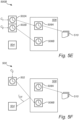
- Figures 2A and 2B show some alternative configurations of a plurality of power grid devices 202, 204, 206, in an example power grid subsystem of a substation 200.
- the substation 200 may comprise a station clock 202 acting as a time master for the substation 200.
- the station clock 202 may receive a clock signal C 1 from an external clock signal source (not shown) such as a GNSS satellite or the like.
- the station clock 202 may then distribute this clock signal C 1 amongst a plurality of devices 206A, 206B, 206C...206N, collectively referred to as 'devices 206'.
- the devices 206 may be computing devices having CPUs and I/O boards, and may be configured to perform control or monitoring operations for one or more converters in the substation 200, for example.
- the devices 206 may each comprise an internal clock (not shown) that follows the clock signal C 1 provided to them by the station clock 202. That is, the internal clocks of the devices 206 may regularly or in an ongoing fashion synchronize their internal clocks according to the clock signal C 1 provided by the station clock 202, wherein the clock signal C 1 may be provided as a pulse per second (PPS) signal, a precision time protocol (PTP) signal, or another type of clock signal.
- PPS pulse per second
- PTP precision time protocol
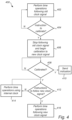
- a station clock 202 or a designated or (to-be-)elected clock-leader unit 204 may monitor 302 for changes in the clock signal C 1 .
- one of the devices 206 may detect an unstable or changeable clock signal C 1 and may signal to the responsible monitor, i.e. the clock leader unit 204, for such changes.
- a change in the clock signal C 1 may be signalled in an incoming PTP signal, or may be noticed first by one of the devices 206, in some examples.
- the change in the clock signal C 1 may have many causes and may comprise a jump forwards or backwards in time, for example to correct the alignment of the station clock 202 with an external clock signal source.
- a new clock signal (e.g., C 2 , not shown) may be detected (step 304: Y), which may trigger the election of a clock-leader unit 204 if one has not already been pre-selected or if a dedicated unit such as the enhanced station clock 203 shown in figure 2A is provided.
- one of the devices 206 may be elected as a clock-leader unit 204.
- This election may be temporary or persistent thereafter, and may be based on one or more of a proximity to the station clock 202 (e.g., in terms of communication latency), a central position amongst the group of devices 206 (e.g., for equal latency in communications therewith), or some other factor(s).
- the devices 206 not elected as being a clock-leader unit 204 may be referred to as clock-follower units 206. That is, in figure 2A , all of the devices 206 are clock-follower units 206 because the clock-leader unit 204 is a separate component incorporated into the enhanced station clock 203. However, in figure 2B , the device 206D is elected as being the clock-leader unit 204 such that the remaining devices 206A, 206B, 206C...206N are clock-follower units.
- the clock-leader unit 204 may send 306 an instruction to the plurality of clock-follower units 206 to calibrate based on a new clock signal.
- the clock-leader unit 204 may then determine whether a confirmation has been obtained as to whether the plurality of clock-follower units 206 have completed calibration, see step 308 in the illustrated method 300.
- Obtaining 308 a confirmation that the plurality of clock-follower units has completed calibration may comprise waiting 310 until either expiry of a timer T E or until indications I CF_1 ⁇ N have been received from all of the N clock-follower units 206 which rely on the station clock 202 for their clock signal, i.e., all of the clock-follower units 206 for which the clock-leader unit 204 is responsible for during the resynchronization process.
- the clock-leader unit 204 may send 312 an instruction to the plurality of clock-follower units 206 to follow the new clock signal.
- the clock-follower units 206 may transition to following the new clock signal as soon as they receive the instruction from the clock-leader unit, or the instruction from the clock-leader unit may further comprise information about a transitioning time at which the transition should take place.
- a device 206D may be selected such that the latency in communications between it and other devices 206 is substantially even for all devices 206, and hence this device 206D may be elected as a clock-leader unit 204 such that the clock-follower units 206 receive instructions therefrom at substantially a same time.
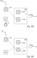
- Figure 4 and figures 5A to 5H illustrate an example execution of the previously described method 300 from the perspective of a clock-follower unit 506. That is, figure 4 illustrates a method 400 for performance by a clock-follower unit 506 to synchronize a clock 508A, 508B therein.
- the arrangement 500 comprises a clock-follower unit 506 having a first internal clock 508A and a second internal clock 508B, which may in reality be separately operable portions of a same clock.
- the clock-follower unit 506 may be in data communication with a station clock 502 (similar in its function to the station clock 202 discussed above) and a clock-leader unit 504 (similar in its function to the clock-leader unit 204 discussed above).
- the clock-follower unit 506 may be connected to the station clock 502 and the clock-leader unit 504 via any suitable wired or wireless data connections, and using any suitable data communication protocol or language.
- the clock-follower unit 506 may be part of a device responsible for timestamping records 510, wherein the records 510 may, for example, be measurements of a phase angle of an AC voltage signal output or input into a converter or converter controller, or some other measurement or determination relevant for power grid operations.
- the timestamps applied to the records 510 may, for example, be in UTC format or another suitable time format for use in, for example, comparing with other records having a matching timestamp (e.g., derived from a similar device) as part of a control or fault detection system.
- the method 400 may begin with the clock-follower unit 506 timestamping the records 510 using the first internal clock 508A.
- the first internal clock 508A whilst being used for said timestamping, may be following a first clock signal C 1 (which will then be referred to as an "old" clock signal) provided by the station clock 502.
- a new clock signal C 2 incoming into and being provided by the station clock 502 may be detected.
- the station 502 notifies the clock-leader unit 504 of this change.
- the clock-follower unit 506 itself (e.g., using the first internal clock 508A) may detect a changed clock signal C 2 , which may appear as unstable time, and may notify the clock-leader unit 504.
- the clock-leader unit 504 may send an instruction to the clock-follower unit 506 to calibrate based on the new clock signal C 2 .
- the clock-follower unit 506 may monitor for such instructions, as illustrated in step 404 of the method shown in figure 4 .
- the clock-follower unit 506 may stop following the old clock signal C 1 and begin calibration based on the new clock signal C 2 , as shown in figure 5D .
- the clock-leader unit 504 may explicitly instruct the clock-follower unit 506 to stop following the old clock signal C 1 , and in other examples this may instead be implicit.
- the first internal clock 508A may then decouple from the clock signal provided by the station clock 502, and may enter what can be referred to as 'hold-over' mode, whereby the first internal clock 508A continues to oscillate as before but no longer maintains a synchronization based on an input clock signal from the station clock 502.
- the first internal clock 508A may be substantially aligned with the old clock signal C 1 and may remain in near-synchronization therewith because of the inherent inertia of the first internal clock 508A.
- different clock-follower units may be in substantial synchronization with each other, despite being in hold-over mode.
- the longer the first internal clocks 508A of clock-follower units are not following a clock signal the more they may fall out of synchronization with each other.
- the first internal clock 508A of the clock-follower unit 506 may not stop following the old clock signal C 1 .
- the station clock 502 may be configured to provide two clock signals C 1 and C 2 , such that the new clock signal C 2 may be provided in parallel with the old clock signal C 1 , at least until the clock-follower unit(s) 506 has calibrated to the new clock signal C 2 .
- time operations may be performed using the first internal clock 508A. That is, the first internal clock 508A may be used to provide timestamps for the records 510 during the calibration.
- the clock-follower unit 506 may send an indication I CF to the clock-leader unit 504 that it has completed calibration, as shown in figure 5F .
- the clock-follower unit 506 may not send an indication I CF that it has completed calibration. Instead, the clock-leader unit 504 may await a signal T E from the expiry of a timer 512.
- the clock-leader unit 504 may send an instruction to the clock-follower unit(s) to follow the new clock signal C 2 .
- the clock-follower unit 506 may monitor for an instruction to follow a new clock signal C 2 , as shown in step 412 of the method 400 illustrated in figure 4 . As shown in step 414, and whilst the clock-follower unit 506 has not yet received an instruction to follow the new clock signal (step 412: N), the clock-follower unit may perform time operations using the first internal clock 508A, for example whilst in hold-over mode, as described above.
- the clock-follower unit 506 may transition to performing time operations, i.e. timestamping records 510, following the new clock signal C 2 , as illustrated in figure 5H , and see step 416 in the method 400 of figure 4 .
- the clock-follower unit 506 may transition from timestamping the records 510 using the first internal clock 508A in hold-over mode to timestamping the records 510 using the second internal clock 508B following the new clock signal C 2 provided by the station clock 502.
- the method 400 may then repeat if a further change to the clock signal C 2 is detected, although it will be appreciated that, in such a repeated performance of the method, the first internal clock 508A and the second internal clock 508B may swap their functions as described above.
- the foregoing description of the method 400 performed by the clock-follower unit 506 may be performed by each clock-follower unit in a plurality of clock-follower units.
- the plurality of clock-follower units may all take their clock signal from the station clock 502 and be in communication with the clock-leader unit 504.
- clock-leader unit 504 will await confirmation that all of the clock-follower units have completed calibration before instructing the clock-follower units to start following the new clock signal C 2 , it can be ensured that the timestamping of records performed by respective devices acting as clock-follower units can stay substantially in synchronization with each other even during a resynchronization process. Thus, the risk of faults or false detections thereof may be advantageously reduced.
Landscapes
- Engineering & Computer Science (AREA)
- Computer Networks & Wireless Communication (AREA)
- Signal Processing (AREA)
- Physics & Mathematics (AREA)
- Theoretical Computer Science (AREA)
- Electromagnetism (AREA)
- General Engineering & Computer Science (AREA)
- General Physics & Mathematics (AREA)
- Electric Clocks (AREA)
- Synchronisation In Digital Transmission Systems (AREA)
Claims (15)
- Computerimplementiertes Verfahren zum Synchronisieren von Takten in Stromnetzvorrichtungen, wobei das Verfahren durch eine Taktführungseinheit durchgeführt wird und das Verfahren Folgendes umfasst:Empfangen (304) einer Angabe eines neuen Taktsignals, dem mehrere Taktfolgereinheiten folgen sollen, zur Verwendung beim Synchronisieren von Takten der mehreren Taktfolgereinheiten;Senden (306) eines Befehls zu den mehreren Taktfolgereinheiten, auf der Grundlage des neuen Taktsignals zu kalibrieren;Erhalten einer Bestätigung (308), dass die mehreren Taktfolgereinheiten eine Kalibrierung abgeschlossen haben; undSenden (312) in Reaktion auf das Erhalten der Bestätigung eines Befehls zu den mehreren Taktfolgereinheiten, dem neuen Taktsignal zu folgen.
- Verfahren nach Anspruch 1, wobei das Erhalten einer Bestätigung, dass die mehreren Taktfolgereinheiten eine Kalibrierung abgeschlossen haben, ein Warten umfasst, dass ein Verzögerungszeitraum abgelaufen ist, wobei der Verzögerungszeitraum konfiguriert ist, sicherzustellen, dass jede der Taktfolgereinheiten Zeit hat, eine Kalibrierung abzuschließen.
- Verfahren nach Anspruch 1, wobei das Erhalten einer Bestätigung, dass jede der Taktfolgereinheiten eine Kalibrierung abgeschlossen hat, ein Empfangen von Angaben von sämtlichen Taktfolgereinheiten umfasst, dass sie eine Kalibrierung abgeschlossen haben.
- Verfahren nach Anspruch 3, wobei eine Angabe, die von einer Taktfolgereinheit empfangen wurde, um eine abgeschlossene Kalibrierung anzugeben, eine Kennung der Taktfolgereinheit umfasst, die die Angabe gesendet hat.
- Verfahren nach einem vorhergehenden Anspruch, das ferner Folgendes umfasst:
in Reaktion auf ein Empfangen der Angabe eines neuen Taktsignals Anweisen der mehreren Taktfolgereinheiten, das Folgen eines alten Taktsignals zu beenden. - Verfahren nach Anspruch 5, das ferner Folgendes umfasst:
Senden eines Befehls zu einer oder mehreren der mehreren Taktfolgereinheiten, einen Neusynchronisationsprozess in Reaktion auf ein Bestimmen abzubrechen, dass das neue Taktsignal eine Zeitdifferenz in Bezug auf das alte Taktsignal besitzt, die kleiner als ein Schwellenwertbetrag ist. - Verfahren nach einem vorhergehenden Anspruch, wobei das Anweisen der Taktfolgereinheiten, dem neuen Taktsignal zu folgen, Folgendes umfasst:Bestimmen einer Übergangszeit damit die Taktfolgereinheiten dazu übergehen, dem neuen Taktsignal zu folgen; undKommunizieren der Übergangszeit zu den mehreren Taktfolgereinheiten derart, dass die Taktfolgereinheiten zur Übergangszeit gleichzeitig dazu übergehen, dem neuen Taktsignal zu folgen.
- Verfahren nach einem vorhergehenden Anspruch, wobei die Angabe des neuen Taktsignals von Folgendem empfangen wird:einer der Taktfolgereinheiten odereiner externen Taktsignalquelle, die sich außerhalb der Stromnetzvorrichtungen befindet.
- Verfahren nach einem vorhergehenden Anspruch, wobei die Taktführungseinheit aus mehreren Stromnetzvorrichtungen auf der Grundlage von Folgendem gewählt wird:
einem vorab zugewiesenen Taktführungsstatus und/oder einer Nähe zu einer externen Taktsignalquelle, die sich außerhalb der Stromnetzvorrichtungen befindet. - Verfahren zum zeitlichen Synchronisieren einer Stromnetzvorrichtung, wobei die Stromnetzvorrichtung (506) einen ersten internen Takt (508A) und einen zweiten internen Takt (508B) umfasst und das Verfahren ein Durchführen der folgenden Schritte ist:Empfangen eines (404) Befehls, auf der Grundlage eines neuen Taktsignals zu kalibrieren;Durchführen von Zeitoperationen unter Verwendung des ersten internen Takts;Kalibrieren des zweiten internen Takts auf der Grundlage des neuen Taktsignals;Empfangen eines Befehls (412), dem neuen Taktsignal zu folgen; undin Reaktion auf ein Empfangen des Befehls, dem neuen Taktsignal zu folgen, Durchführen von Zeitoperationen (416) unter Verwendung des zweiten internen Takts.
- Verfahren nach Anspruch 10, das ferner Folgendes umfasst:Folgen mit dem ersten internen Takt einem alten Taktsignal;in Reaktion auf ein Empfangen eines Befehls, auf der Grundlage eines neuen Taktsignals zu kalibrieren, Beenden des Folgens des alten Taktsignals.
- Datenverarbeitungsvorrichtung, die Mittel umfasst, die konfiguriert sind, das Verfahren nach einem vorhergehenden Anspruch auszuführen.
- Computerprogramm das Befehle enthält, die, wenn das Programm durch einen Computer ausgeführt wird, den Computer veranlassen, das Verfahren nach einem der Ansprüche 1 bis 11 auszuführen.
- Computerlesbares Medium, das Befehle enthält, die, wenn sie durch einen Computer ausgeführt werden, bewirken, dass der Computer das Verfahren nach einem der Ansprüche 1 bis 11 ausführt.
- Stromnetzsystem, das Folgendes umfasst:mehrere Stromnetzvorrichtungen in Datenkommunikation, wobei jede Stromnetzvorrichtung mindestens einen Takt aufweist;wobei mindestens eine der mehreren Stromnetzvorrichtungen die Datenverarbeitungsvorrichtung nach Anspruch 12 umfasst.
Priority Applications (6)
| Application Number | Priority Date | Filing Date | Title |
|---|---|---|---|
| EP22189047.8A EP4318985B1 (de) | 2022-08-05 | 2022-08-05 | Koordinierte resynchronisierung von uhren in energienetzsystemen |
| EP23741068.3A EP4566203A1 (de) | 2022-08-05 | 2023-07-14 | Koordinierte resynchronisation von takten in stromnetzsystemen |
| CN202380054210.6A CN119563297A (zh) | 2022-08-05 | 2023-07-14 | 电网系统中时钟的协调重新同步 |
| JP2025506166A JP7789267B2 (ja) | 2022-08-05 | 2023-07-14 | パワーグリッドシステムにおけるクロックの協調再同期 |
| US19/099,569 US20260058747A1 (en) | 2022-08-05 | 2023-07-14 | Co-ordinated resynchronization of clocks in power grid systems |
| PCT/EP2023/069691 WO2024028085A1 (en) | 2022-08-05 | 2023-07-14 | Co-ordinated resynchronization of clocks in power grid systems |
Applications Claiming Priority (1)
| Application Number | Priority Date | Filing Date | Title |
|---|---|---|---|
| EP22189047.8A EP4318985B1 (de) | 2022-08-05 | 2022-08-05 | Koordinierte resynchronisierung von uhren in energienetzsystemen |
Publications (2)
| Publication Number | Publication Date |
|---|---|
| EP4318985A1 EP4318985A1 (de) | 2024-02-07 |
| EP4318985B1 true EP4318985B1 (de) | 2025-05-07 |
Family
ID=82851693
Family Applications (2)
| Application Number | Title | Priority Date | Filing Date |
|---|---|---|---|
| EP22189047.8A Active EP4318985B1 (de) | 2022-08-05 | 2022-08-05 | Koordinierte resynchronisierung von uhren in energienetzsystemen |
| EP23741068.3A Pending EP4566203A1 (de) | 2022-08-05 | 2023-07-14 | Koordinierte resynchronisation von takten in stromnetzsystemen |
Family Applications After (1)
| Application Number | Title | Priority Date | Filing Date |
|---|---|---|---|
| EP23741068.3A Pending EP4566203A1 (de) | 2022-08-05 | 2023-07-14 | Koordinierte resynchronisation von takten in stromnetzsystemen |
Country Status (5)
| Country | Link |
|---|---|
| US (1) | US20260058747A1 (de) |
| EP (2) | EP4318985B1 (de) |
| JP (1) | JP7789267B2 (de) |
| CN (1) | CN119563297A (de) |
| WO (1) | WO2024028085A1 (de) |
Family Cites Families (4)
| Publication number | Priority date | Publication date | Assignee | Title |
|---|---|---|---|---|
| CN102123024B (zh) * | 2011-03-17 | 2015-06-03 | 中兴通讯股份有限公司 | 一种时钟源设备切换选择方法、系统及装置 |
| US9735905B2 (en) * | 2012-08-10 | 2017-08-15 | Avago Technologies General Ip (Singapore) Pte. Ltd. | Systems and methods for implementing bi-directional synchronization propagation |
| CN111917503B (zh) | 2019-05-10 | 2024-09-06 | 日立能源有限公司 | 用于提供时钟信号的方法和装置 |
| PH12021552935A1 (en) | 2019-05-22 | 2022-07-25 | Vit Tall Llc | Multi-clock synchronization in power grids |
-
2022
- 2022-08-05 EP EP22189047.8A patent/EP4318985B1/de active Active
-
2023
- 2023-07-14 CN CN202380054210.6A patent/CN119563297A/zh active Pending
- 2023-07-14 JP JP2025506166A patent/JP7789267B2/ja active Active
- 2023-07-14 WO PCT/EP2023/069691 patent/WO2024028085A1/en not_active Ceased
- 2023-07-14 EP EP23741068.3A patent/EP4566203A1/de active Pending
- 2023-07-14 US US19/099,569 patent/US20260058747A1/en active Pending
Also Published As
| Publication number | Publication date |
|---|---|
| JP7789267B2 (ja) | 2025-12-19 |
| US20260058747A1 (en) | 2026-02-26 |
| EP4566203A1 (de) | 2025-06-11 |
| CN119563297A (zh) | 2025-03-04 |
| JP2025525953A (ja) | 2025-08-07 |
| WO2024028085A1 (en) | 2024-02-08 |
| EP4318985A1 (de) | 2024-02-07 |
Similar Documents
| Publication | Publication Date | Title |
|---|---|---|
| CN101867469B (zh) | 一种精密同步时钟的实现方法 | |
| CN101447861B (zh) | Ieee 1588时间同步系统及其实现方法 | |
| US8108558B2 (en) | Circuit arrangement and method for synchronization of clocks in a network | |
| EP1717978B1 (de) | Zeitsynchronisierung, deterministische Datenübermittlung und Redundanz für kaskadierten Knoten in einem vollduplex-Ethernet Netzwerk | |
| CN108259109B (zh) | Ptp域中的网络设备及tod同步方法 | |
| US11456849B2 (en) | Method and apparatus for synchronizing different communication ports | |
| EP3026515A1 (de) | Programmierbares steuerungssystem und steuerung dafür | |
| US10320507B2 (en) | Method for determining a propagation time of a telegram in a communication network, and corresponding network components | |
| US7343437B2 (en) | Synchronization method and control system for the time synchronization of slave units and a synchronizable slave unit | |
| US20170214479A1 (en) | Method for transmitting time synchronization messages in a communication network, network component, and communication network | |
| CN109302255B (zh) | 时间同步控制方法、装置、系统及计算机可读存储介质 | |
| JP2011193457A (ja) | 時間同期を行うためのシステムおよび方法 | |
| WO2010116968A1 (ja) | ネットワーク端末、ネットワークシステム、時刻同期方法、および時刻同期プログラム | |
| EP4318985B1 (de) | Koordinierte resynchronisierung von uhren in energienetzsystemen | |
| CN103051409A (zh) | 一种短波信道同步装置及短波信道同步切换控制系统 | |
| US7249272B1 (en) | Apparatus and method for coordinating activities of one or more computers | |
| JP5626589B2 (ja) | ネットワーク機器、および同機器における時刻同期方法 | |
| CN111443685B (zh) | 用于在控制设备中提供通用时间的方法以及控制设备 | |
| JP2020077929A (ja) | 時刻配信装置、同期システム、及びプログラム | |
| US12235674B2 (en) | Time synchronization between a master and a slave in a network | |
| EP4199384B1 (de) | Verfahren und vorrichtung zur bestimmung eines taktfrequenzversatzes | |
| CN112468254B (zh) | 一种可重构分布式节点高精度授时同步系统及方法 | |
| CN115801164A (zh) | 网络中的时间同步 | |
| Wu et al. | Synchronizing device clocks using IEEE 1588 and Blackfin embedded processors | |
| JP2016152487A (ja) | 時刻同期方法および時刻同期装置 |
Legal Events
| Date | Code | Title | Description |
|---|---|---|---|
| PUAI | Public reference made under article 153(3) epc to a published international application that has entered the european phase |
Free format text: ORIGINAL CODE: 0009012 |
|
| STAA | Information on the status of an ep patent application or granted ep patent |
Free format text: STATUS: THE APPLICATION HAS BEEN PUBLISHED |
|
| AK | Designated contracting states |
Kind code of ref document: A1 Designated state(s): AL AT BE BG CH CY CZ DE DK EE ES FI FR GB GR HR HU IE IS IT LI LT LU LV MC MK MT NL NO PL PT RO RS SE SI SK SM TR |
|
| STAA | Information on the status of an ep patent application or granted ep patent |
Free format text: STATUS: REQUEST FOR EXAMINATION WAS MADE |
|
| 17P | Request for examination filed |
Effective date: 20240502 |
|
| RBV | Designated contracting states (corrected) |
Designated state(s): AL AT BE BG CH CY CZ DE DK EE ES FI FR GB GR HR HU IE IS IT LI LT LU LV MC MK MT NL NO PL PT RO RS SE SI SK SM TR |
|
| GRAP | Despatch of communication of intention to grant a patent |
Free format text: ORIGINAL CODE: EPIDOSNIGR1 |
|
| STAA | Information on the status of an ep patent application or granted ep patent |
Free format text: STATUS: GRANT OF PATENT IS INTENDED |
|
| RIC1 | Information provided on ipc code assigned before grant |
Ipc: H02J 13/00 20060101ALN20240830BHEP Ipc: H04J 3/14 20060101ALI20240830BHEP Ipc: H04J 3/06 20060101AFI20240830BHEP |
|
| RIC1 | Information provided on ipc code assigned before grant |
Ipc: H02J 13/00 20060101ALN20240911BHEP Ipc: H04J 3/14 20060101ALI20240911BHEP Ipc: H04J 3/06 20060101AFI20240911BHEP |
|
| INTG | Intention to grant announced |
Effective date: 20240919 |
|
| GRAJ | Information related to disapproval of communication of intention to grant by the applicant or resumption of examination proceedings by the epo deleted |
Free format text: ORIGINAL CODE: EPIDOSDIGR1 |
|
| STAA | Information on the status of an ep patent application or granted ep patent |
Free format text: STATUS: REQUEST FOR EXAMINATION WAS MADE |
|
| GRAP | Despatch of communication of intention to grant a patent |
Free format text: ORIGINAL CODE: EPIDOSNIGR1 |
|
| STAA | Information on the status of an ep patent application or granted ep patent |
Free format text: STATUS: GRANT OF PATENT IS INTENDED |
|
| INTC | Intention to grant announced (deleted) | ||
| RIC1 | Information provided on ipc code assigned before grant |
Ipc: H02J 13/00 20060101ALN20250106BHEP Ipc: H04J 3/14 20060101ALI20250106BHEP Ipc: H04J 3/06 20060101AFI20250106BHEP |
|
| INTG | Intention to grant announced |
Effective date: 20250128 |
|
| GRAS | Grant fee paid |
Free format text: ORIGINAL CODE: EPIDOSNIGR3 |
|
| GRAA | (expected) grant |
Free format text: ORIGINAL CODE: 0009210 |
|
| STAA | Information on the status of an ep patent application or granted ep patent |
Free format text: STATUS: THE PATENT HAS BEEN GRANTED |
|
| P01 | Opt-out of the competence of the unified patent court (upc) registered |
Free format text: CASE NUMBER: APP_12094/2025 Effective date: 20250312 |
|
| AK | Designated contracting states |
Kind code of ref document: B1 Designated state(s): AL AT BE BG CH CY CZ DE DK EE ES FI FR GB GR HR HU IE IS IT LI LT LU LV MC MK MT NL NO PL PT RO RS SE SI SK SM TR |
|
| REG | Reference to a national code |
Ref country code: GB Ref legal event code: FG4D |
|
| REG | Reference to a national code |
Ref country code: CH Ref legal event code: EP |
|
| REG | Reference to a national code |
Ref country code: DE Ref legal event code: R096 Ref document number: 602022014154 Country of ref document: DE |
|
| REG | Reference to a national code |
Ref country code: IE Ref legal event code: FG4D |
|
| REG | Reference to a national code |
Ref country code: NL Ref legal event code: MP Effective date: 20250507 |
|
| PG25 | Lapsed in a contracting state [announced via postgrant information from national office to epo] |
Ref country code: FI Free format text: LAPSE BECAUSE OF FAILURE TO SUBMIT A TRANSLATION OF THE DESCRIPTION OR TO PAY THE FEE WITHIN THE PRESCRIBED TIME-LIMIT Effective date: 20250507 Ref country code: ES Free format text: LAPSE BECAUSE OF FAILURE TO SUBMIT A TRANSLATION OF THE DESCRIPTION OR TO PAY THE FEE WITHIN THE PRESCRIBED TIME-LIMIT Effective date: 20250507 Ref country code: PT Free format text: LAPSE BECAUSE OF FAILURE TO SUBMIT A TRANSLATION OF THE DESCRIPTION OR TO PAY THE FEE WITHIN THE PRESCRIBED TIME-LIMIT Effective date: 20250908 |
|
| PGFP | Annual fee paid to national office [announced via postgrant information from national office to epo] |
Ref country code: DE Payment date: 20250820 Year of fee payment: 4 |
|
| REG | Reference to a national code |
Ref country code: LT Ref legal event code: MG9D |
|
| PG25 | Lapsed in a contracting state [announced via postgrant information from national office to epo] |
Ref country code: NO Free format text: LAPSE BECAUSE OF FAILURE TO SUBMIT A TRANSLATION OF THE DESCRIPTION OR TO PAY THE FEE WITHIN THE PRESCRIBED TIME-LIMIT Effective date: 20250807 Ref country code: GR Free format text: LAPSE BECAUSE OF FAILURE TO SUBMIT A TRANSLATION OF THE DESCRIPTION OR TO PAY THE FEE WITHIN THE PRESCRIBED TIME-LIMIT Effective date: 20250808 |
|
| PG25 | Lapsed in a contracting state [announced via postgrant information from national office to epo] |
Ref country code: NL Free format text: LAPSE BECAUSE OF FAILURE TO SUBMIT A TRANSLATION OF THE DESCRIPTION OR TO PAY THE FEE WITHIN THE PRESCRIBED TIME-LIMIT Effective date: 20250507 Ref country code: PL Free format text: LAPSE BECAUSE OF FAILURE TO SUBMIT A TRANSLATION OF THE DESCRIPTION OR TO PAY THE FEE WITHIN THE PRESCRIBED TIME-LIMIT Effective date: 20250507 |
|
| REG | Reference to a national code |
Ref country code: AT Ref legal event code: MK05 Ref document number: 1793663 Country of ref document: AT Kind code of ref document: T Effective date: 20250507 |
|
| PG25 | Lapsed in a contracting state [announced via postgrant information from national office to epo] |
Ref country code: BG Free format text: LAPSE BECAUSE OF FAILURE TO SUBMIT A TRANSLATION OF THE DESCRIPTION OR TO PAY THE FEE WITHIN THE PRESCRIBED TIME-LIMIT Effective date: 20250507 |
|
| PG25 | Lapsed in a contracting state [announced via postgrant information from national office to epo] |
Ref country code: HR Free format text: LAPSE BECAUSE OF FAILURE TO SUBMIT A TRANSLATION OF THE DESCRIPTION OR TO PAY THE FEE WITHIN THE PRESCRIBED TIME-LIMIT Effective date: 20250507 |
|
| PG25 | Lapsed in a contracting state [announced via postgrant information from national office to epo] |
Ref country code: AT Free format text: LAPSE BECAUSE OF FAILURE TO SUBMIT A TRANSLATION OF THE DESCRIPTION OR TO PAY THE FEE WITHIN THE PRESCRIBED TIME-LIMIT Effective date: 20250507 |
|
| PGFP | Annual fee paid to national office [announced via postgrant information from national office to epo] |
Ref country code: FR Payment date: 20250828 Year of fee payment: 4 |
|
| PG25 | Lapsed in a contracting state [announced via postgrant information from national office to epo] |
Ref country code: RS Free format text: LAPSE BECAUSE OF FAILURE TO SUBMIT A TRANSLATION OF THE DESCRIPTION OR TO PAY THE FEE WITHIN THE PRESCRIBED TIME-LIMIT Effective date: 20250807 |
|
| PG25 | Lapsed in a contracting state [announced via postgrant information from national office to epo] |
Ref country code: IS Free format text: LAPSE BECAUSE OF FAILURE TO SUBMIT A TRANSLATION OF THE DESCRIPTION OR TO PAY THE FEE WITHIN THE PRESCRIBED TIME-LIMIT Effective date: 20250907 |
|
| PG25 | Lapsed in a contracting state [announced via postgrant information from national office to epo] |
Ref country code: LV Free format text: LAPSE BECAUSE OF FAILURE TO SUBMIT A TRANSLATION OF THE DESCRIPTION OR TO PAY THE FEE WITHIN THE PRESCRIBED TIME-LIMIT Effective date: 20250507 |
|
| PG25 | Lapsed in a contracting state [announced via postgrant information from national office to epo] |
Ref country code: SM Free format text: LAPSE BECAUSE OF FAILURE TO SUBMIT A TRANSLATION OF THE DESCRIPTION OR TO PAY THE FEE WITHIN THE PRESCRIBED TIME-LIMIT Effective date: 20250507 Ref country code: DK Free format text: LAPSE BECAUSE OF FAILURE TO SUBMIT A TRANSLATION OF THE DESCRIPTION OR TO PAY THE FEE WITHIN THE PRESCRIBED TIME-LIMIT Effective date: 20250507 |
|
| PG25 | Lapsed in a contracting state [announced via postgrant information from national office to epo] |
Ref country code: CZ Free format text: LAPSE BECAUSE OF FAILURE TO SUBMIT A TRANSLATION OF THE DESCRIPTION OR TO PAY THE FEE WITHIN THE PRESCRIBED TIME-LIMIT Effective date: 20250507 |
|
| PG25 | Lapsed in a contracting state [announced via postgrant information from national office to epo] |
Ref country code: EE Free format text: LAPSE BECAUSE OF FAILURE TO SUBMIT A TRANSLATION OF THE DESCRIPTION OR TO PAY THE FEE WITHIN THE PRESCRIBED TIME-LIMIT Effective date: 20250507 |
|
| PG25 | Lapsed in a contracting state [announced via postgrant information from national office to epo] |
Ref country code: SK Free format text: LAPSE BECAUSE OF FAILURE TO SUBMIT A TRANSLATION OF THE DESCRIPTION OR TO PAY THE FEE WITHIN THE PRESCRIBED TIME-LIMIT Effective date: 20250507 |
|
| PG25 | Lapsed in a contracting state [announced via postgrant information from national office to epo] |
Ref country code: IT Free format text: LAPSE BECAUSE OF FAILURE TO SUBMIT A TRANSLATION OF THE DESCRIPTION OR TO PAY THE FEE WITHIN THE PRESCRIBED TIME-LIMIT Effective date: 20250507 |
|
| REG | Reference to a national code |
Ref country code: DE Ref legal event code: R097 Ref document number: 602022014154 Country of ref document: DE |
|
| PLBE | No opposition filed within time limit |
Free format text: ORIGINAL CODE: 0009261 |
|
| STAA | Information on the status of an ep patent application or granted ep patent |
Free format text: STATUS: NO OPPOSITION FILED WITHIN TIME LIMIT |
|
| PG25 | Lapsed in a contracting state [announced via postgrant information from national office to epo] |
Ref country code: RO Free format text: LAPSE BECAUSE OF FAILURE TO SUBMIT A TRANSLATION OF THE DESCRIPTION OR TO PAY THE FEE WITHIN THE PRESCRIBED TIME-LIMIT Effective date: 20250507 |
|
| REG | Reference to a national code |
Ref country code: CH Ref legal event code: L10 Free format text: ST27 STATUS EVENT CODE: U-0-0-L10-L00 (AS PROVIDED BY THE NATIONAL OFFICE) Effective date: 20260318 |
|
| REG | Reference to a national code |
Ref country code: CH Ref legal event code: H13 Free format text: ST27 STATUS EVENT CODE: U-0-0-H10-H13 (AS PROVIDED BY THE NATIONAL OFFICE) Effective date: 20260324 |