EP4313571B1 - Werkzeug mit genutetem kern zur herstellung von luftreifen, die durch verstärkungsstreben durch den inflationshohlraum verstärkt sind - Google Patents
Werkzeug mit genutetem kern zur herstellung von luftreifen, die durch verstärkungsstreben durch den inflationshohlraum verstärkt sind Download PDFInfo
- Publication number
- EP4313571B1 EP4313571B1 EP22714903.6A EP22714903A EP4313571B1 EP 4313571 B1 EP4313571 B1 EP 4313571B1 EP 22714903 A EP22714903 A EP 22714903A EP 4313571 B1 EP4313571 B1 EP 4313571B1
- Authority
- EP
- European Patent Office
- Prior art keywords
- stays
- crown
- tyre
- lug
- core
- Prior art date
- Legal status (The legal status is an assumption and is not a legal conclusion. Google has not performed a legal analysis and makes no representation as to the accuracy of the status listed.)
- Active
Links
Images





Classifications
-
- B—PERFORMING OPERATIONS; TRANSPORTING
- B29—WORKING OF PLASTICS; WORKING OF SUBSTANCES IN A PLASTIC STATE IN GENERAL
- B29D—PRODUCING PARTICULAR ARTICLES FROM PLASTICS OR FROM SUBSTANCES IN A PLASTIC STATE
- B29D30/00—Producing pneumatic or solid tyres or parts thereof
- B29D30/06—Pneumatic tyres or parts thereof (e.g. produced by casting, moulding, compression moulding, injection moulding, centrifugal casting)
- B29D30/0601—Vulcanising tyres; Vulcanising presses for tyres
- B29D30/0661—Rigid cores therefor, e.g. annular or substantially toroidal cores
-
- B—PERFORMING OPERATIONS; TRANSPORTING
- B29—WORKING OF PLASTICS; WORKING OF SUBSTANCES IN A PLASTIC STATE IN GENERAL
- B29D—PRODUCING PARTICULAR ARTICLES FROM PLASTICS OR FROM SUBSTANCES IN A PLASTIC STATE
- B29D30/00—Producing pneumatic or solid tyres or parts thereof
- B29D30/06—Pneumatic tyres or parts thereof (e.g. produced by casting, moulding, compression moulding, injection moulding, centrifugal casting)
- B29D30/08—Building tyres
- B29D30/10—Building tyres on round cores, i.e. the shape of the core is approximately identical with the shape of the completed tyre
- B29D30/12—Cores
-
- B—PERFORMING OPERATIONS; TRANSPORTING
- B29—WORKING OF PLASTICS; WORKING OF SUBSTANCES IN A PLASTIC STATE IN GENERAL
- B29D—PRODUCING PARTICULAR ARTICLES FROM PLASTICS OR FROM SUBSTANCES IN A PLASTIC STATE
- B29D30/00—Producing pneumatic or solid tyres or parts thereof
- B29D30/06—Pneumatic tyres or parts thereof (e.g. produced by casting, moulding, compression moulding, injection moulding, centrifugal casting)
- B29D30/08—Building tyres
- B29D30/10—Building tyres on round cores, i.e. the shape of the core is approximately identical with the shape of the completed tyre
- B29D30/16—Applying the layers; Guiding or stretching the layers during application
- B29D30/1635—Applying the layers; Guiding or stretching the layers during application by feeding a continuous band and moving it back and forth (zig-zag) to form an annular element
-
- B—PERFORMING OPERATIONS; TRANSPORTING
- B29—WORKING OF PLASTICS; WORKING OF SUBSTANCES IN A PLASTIC STATE IN GENERAL
- B29D—PRODUCING PARTICULAR ARTICLES FROM PLASTICS OR FROM SUBSTANCES IN A PLASTIC STATE
- B29D30/00—Producing pneumatic or solid tyres or parts thereof
- B29D30/06—Pneumatic tyres or parts thereof (e.g. produced by casting, moulding, compression moulding, injection moulding, centrifugal casting)
- B29D30/72—Side-walls
Definitions
- the present invention relates to the general field of the manufacture of toroidal tires, and more particularly to pneumatic tires intended to equip vehicle wheels. Examples for the manufacture of pneumatic tires with tools can be found in the patent applications JP 2003311741 A , AT 378 506 B And FR 2583399 A .
- the applicant had the idea of implementing reinforcements of the shroud type which extend within the toric inflation cavity which delimits the tire, and which each connect an anchoring point located in the sidewall or the bead of the tire to an anchoring point located at the top of the tire.
- the objects assigned to the invention therefore aim to remedy the aforementioned drawbacks and to propose a tool according to claim 1, and a manufacturing method according to claim 12, making it possible to obtain a quality braced bandage in a relatively simple and reproducible manner.
- a tool intended for the manufacture of a toroidal bandage comprising a crown intended to form a tread, a first annular bead and a second annular bead designed to allow the bandage to be attached to a mounting support such as a rim, as well as a first sidewall and a second sidewall which connect the crown respectively to the first bead and to the second bead, the crown, the first and second sidewalls and the first and second beads forming as a whole a wall having a concave internal surface which delimits a cavity of the bandage, said tool comprising a toroidal core having, around its central axis, a convex external surface, called a "receiving surface", which has a shape conjugate to the internal surface of the wall of the bandage and which comprises for this purpose a radially external summit zone, intended to receive components constituting the crown of the bandage, and, on either side axially of said zone top, a first lateral
- the use of a core according to the invention makes it possible to position the stays at the desired locations within the volume reserved by the core, and consequently in the region of the space which will subsequently become the cavity of the bandage after said bandage has been formed and the core removed.
- each stay when placing the stays within the core, a portion of each stay is located inside the corresponding passage, and therefore in the region of the space which corresponds to the future cavity of the bandage, while the ends of said stay protrude outside the passage, onto the receiving surface.
- the said ends of each stay are immediately and definitively integrated into the structure of the wall of the tire, while the intermediate portion of the stay in question, located in the passage, is set back from the receiving surface and therefore remains detached and distant from the wall of the tire during and after the installation of the components constituting the wall of the tire, and preferably is thus immediately in the position that the said intermediate portion of the stay will definitively occupy within the cavity of the tire.
- the wall of said bandage is advantageously, in a manner known per se, directly shaped to the desired shape, by simply placing the constituent components of the wall of the bandage on the core.
- the core carrying the bandage is then placed in a mold in order to bake the bandage, which allows the rubber-based components of the wall of the bandage to be vulcanized. After this baking operation, the core is separated from the bandage, thus freeing the bandage cavity and leaving the stays permanently in place in the said cavity.
- the tooling according to the invention therefore makes it possible to obtain immediately, and in a reproducible manner, a suitably shaped stay bandage, without risk of incorrectly positioning or damaging the stays during the manufacture of the bandage.
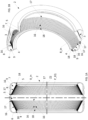
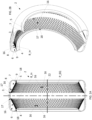
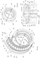
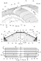
- the present invention relates to a tool 1, as illustrated in particular in the Figures 4A, 4B, 4C , 5A, 5B, 5C And 6A, 6B, 6C , which tool 1 is intended for the manufacture of a toroidal bandage 2, as illustrated in the Figures 1A, 1B , 2A and 2B .
- Such a bandage 2 preferably constitutes a pneumatic bandage intended to equip a wheel of a vehicle, to ensure the connection of said vehicle with the ground.
- the bandage 2 has a shape of revolution around an axis called the “central axis” Z2 which corresponds substantially, in practice, to the axis of rotation of the wheel.
- This central axis Z2 defines three directions conventionally used by those skilled in the art: an axial direction, a radial direction, and a circumferential direction.
- axial direction is meant a vectorially collinear direction, i.e. parallel to the central axis Z2 of the bandage 2, i.e. parallel to the axis of rotation of the bandage.
- radial direction is meant a direction which extends along a radius of the tire, that is to say any direction which is secant and perpendicular to the central axis Z2.
- circumferential direction is meant a direction which is perpendicular to both the axial direction and a radius of the tire, and which therefore corresponds, in a plane normal to the central axis Z2, to the tangent to a circle whose center is on the axis of rotation of the tire.
- meridian plane P_MER, or "radial plane” we mean a plane parallel to, and containing, the central axis Z2. Such a meridian plane is therefore normal to the circumferential direction.
- equatorial plane P_EQ is meant the plane normal to the central axis Z2 and which passes through the radially outermost point of the tire, which is preferably located axially midway between the axially outermost points of the tire. Said equatorial plane therefore axially divides the tire 2 into two toroidal halves, preferably substantially equal, called, by analogy with the terrestrial globe, "hemispheres”.
- Said bandage 2 comprises, in a manner known per se, a crown 3 intended to form a tread, a first annular bead 4 and a second annular bead 5 designed to allow the bandage 2 to be attached to a mounting support such as a rim, as well as a first sidewall 6 and a second sidewall 7 which connect the crown 3 respectively to the first bead 4 and to the second bead 5.
- the top 3, the first and second flanks 6, 7 and the first and second beads 4, 5 form as a whole a wall 8 having a concave internal surface 8_in which delimits a cavity 9 of the bandage 2.
- said cavity 9 of the bandage is toroidal, and advantageously forms the inflation cavity of the bandage 2, which is intended to receive a pressurized fluid, such as air, to support the crown 3 of the pneumatic bandage 2 relative to the rim.
- the bead 4, 5 is located axially set back from the axially most projecting portion of the corresponding flank 6, 7, that is to say that said bead 4, 5 is closer to the equatorial plane P_EQ than the flank 6, 7 to which said bead is connected.
- the flank 6, 7 forms, in section in a meridian plane P_MER, a profile that is generally curved outwards and the end forming the bead 4, 5 is axially re-entrant, so that the cavity 9 has, in section in said meridian plane, substantially a shape of ⁇ (capital Omega).
- the tool 1 comprises a toroidal core 10 having, around its central axis Z10, a convex external surface 10_out, called the “receiving surface” 10_out, which has a shape conjugated to the internal surface 8_in of the wall 8 of the bandage and which comprises for this purpose a radially external top zone 11, intended to receive components constituting the top 3 of the bandage 2, and, on either side axially of said top zone, a first lateral zone 12 folded towards the central axis Z10 of the core and intended to receive components constituting the first flank 6 and the first bead 4 as well as a second lateral zone 13 folded towards the central axis Z10 of the core and intended to receive components constituting the second flank 7 and the second bead 5.
- the core 10 materializes a volume, called “reserved volume”, which is delimited externally by the receiving surface 10_out and which corresponds to the cavity 9 of the bandage 2.
- the core 10 can thus occupy, and therefore temporarily reserve, during the manufacture of the bandage, the volume whose shape and dimensions correspond to those of the cavity 9, a volume which will become the cavity 9 of the bandage 2 when the core 10 has been removed from said bandage 2, during the demolding operation which will complete the manufacturing cycle of the bandage 2.
- central axis Z10 of the core 10, around which said core 10 forms a ring will in practice merge with the central axis Z2 of the bandage 2 manufactured on said core 10.
- central axis one or the other can therefore be designated indifferently by the expression “central axis”.
- the core 10 has a plurality of passages 15 which extend inside the reserved volume, under the receiving surface 10_out, and which open onto said receiving surface 10_out so that each of said passages 15 connects the top zone 11 of the receiving surface 10_out to one of the first and second lateral zones 12, 13 so that the core 10 can receive, inside said passages 15, reinforcing elements 16, called "stays" 16, which are designed to permanently integrate the structure of the bandage 2 and each extend into the cavity 9 of the bandage by connecting a top anchoring point 17 located in the top 3 of the bandage 2 to a lateral anchoring point 18 located in one of the flanks 6, 7 or the beads 4, 5 of the bandage 2.
- the passages 15 thus correspond to empty spaces which are provided in the core 10, inside the reserved volume, to be able to accommodate the stays 16, and thus allow each stay 16 to cross the receiving surface 10_out, a first time to enter the reserved volume, here through the lateral zone 12, 13, and a second time to exit the reserved volume, here in the summit zone 11, or vice versa.
- the shrouds 16 may have different configurations, and in particular a variety of orientations, without departing from the scope of the invention.
- the top 17 and lateral 18 anchor points of each stay 16 are located at the same azimuth around the central axis Z2 of the bandage, so that the stays 16 extend along radial planes containing the central axis Z2 of the bandage.
- the top anchoring points 17 and lateral anchoring points 18 of each stay 16 are angularly offset in azimuth relative to each other around the central axis Z2 of the bandage, so as to create inclined stays 16.
- the bandage 2 may then comprise, in the same hemisphere, and preferably in each of its two hemispheres, two sets of stays 16, so that the stays 16 of the first set each have an angular offset in a first direction, for example in the clockwise direction, between their top anchoring point 17 and their lateral anchoring point 18, while the stays 16 of the second set each have an angular offset in a second opposite direction, for example counterclockwise, between their top anchoring point 17 and their lateral anchoring point 18, so that the shrouds 16 of the first set and the shrouds 16 of the second set, of the same hemisphere, intersect.
- all the lateral anchoring points 18 of the stays 16 of the same hemisphere are located at the same abscissa along the central axis Z2, that is to say that the stays 16 of the same hemisphere preferably emerge from the wall 8 of the bandage 2 along the same fictitious line which corresponds to the intersection of the internal surface 8_in of the wall 8 with a plane normal to the central axis Z2.
- top anchoring points 17 of said stays 16 of the same hemisphere which are preferably all located at the same abscissa along the central axis Z2, preferably distinct from the abscissa of the lateral anchoring points 18.
- the abscissa of the summit anchoring point 17 is preferably closer to the equatorial plane P_EQ than the abscissa of the lateral anchoring point 18.
- each stay 16 is preferably contained in a single hemisphere, in that no stay 16 crosses the equatorial plane P_EQ inside the cavity 9 of the bandage, that is to say that the lateral anchoring point 18 and the top anchoring point 17 which form the two ends of the same section of stay 16 which extends continuously inside the cavity 9, and therefore which form the two successive points by which respectively the stay 16 emerges from the wall 8 to cross the cavity 9 then leaves the cavity 9 to plunge back into the wall 8, are both located in the same hemisphere, on the same side of the equatorial plane P_EQ.
- each guy 16 is intended to work in traction, and therefore to connect the summit anchor point 17 to the corresponding lateral anchor point 18 along a straight line segment, that is to say by geometrically forming a taut, or quasi-taut, rope, under the arc which is formed by the internal surface 8_in of the wall 8 between the top anchoring point 17 and the lateral anchoring point 18 in the bandage 2 at rest, and this so that the stay 16 opposes the mutual distancing of said anchoring points 17, 18 relative to each other, and thus increases the lateral rigidity of the bandage.
- shrouds 16 of the same set of shrouds will preferably be distributed in azimuth around the central axis Z2 in a uniform manner, according to a constant angular repetition pitch P16.
- This angular repetition pitch P16 will preferably be between 0.5 degrees and 5 degrees, preferably between 0.75 degrees and 3 degrees, in particular between 1 degree and 3 degrees, and for example equal to 1.5 degrees.
- Each set of stays 16 may thus have between 72 stays and 480 or even 720 stays, preferably between 120 stays and 360 stays, and for example preferred 240 stays.
- the above angular repetition pitch P16 makes it possible to obtain a good compromise between a number of stays 16 which is on the one hand sufficiently high to obtain effective stiffening of the bandage 2, even in the event of breakage of one or a few stays 16, and on the other hand sufficiently moderate to be able to arrange a corresponding number of passages 15 in the core 10 without excessively weakening the structure of the core 10 or complicating the demolding operations.
- a repetition step P16 of 1.5 degrees will position a stay 16, and therefore a stay passage 15, every 5 mm to 10 mm, and for example approximately every 8 mm, of arc length considered around the central axis Z2, Z10, at the maximum diameter of the internal surface 8_in of the wall 8 of the bandage 2, or, equivalently, in the summit zone 11, at the maximum diameter of the external surface of the core 10 forming the receiving surface 10_out.
- the stays 16 will be made from one or more wire elements, the largest transverse dimension of which will be at least ten times, at least twenty times, or even at least fifty times less than the apparent length of the portion of the stay 16 concerned which extends into the cavity 9, that is to say the length of the stay 16 between the top anchoring point 17 and the corresponding lateral anchoring point 18.
- Said stays 16 may thus be formed from a single-strand or multi-strand wire, made from strands of textile material, polymer material such as aramid, or even metallic material. According to one possible embodiment, the stays 16 will be made from a composite wire made from fiberglass and resin.
- the core 10 according to the invention makes it possible to install said stays 16 in the volume reserved by the core 10, and therefore in the space which will become the cavity 9 of the bandage 2, prior to the constitution of the bandage 2, according to a distribution and an arrangement which will correspond substantially or even exactly to the distribution and arrangement which said stays will have within the finished bandage 2, ready to be mounted on the rim, since the stays 16 remain in place inside the cavity 9, in the desired position, and integral with the bandage 2, when the core 10 is removed. Thanks to the use of a core 10 according to the invention, it is therefore ensured that the bandage 2 will have a well-controlled configuration, and reproducible from one bandage 2 to another.
- the stays 16 are thus sheltered in the passages 15 of the core 10 during the installation of the components constituting the wall 8 of the bandage, there is no risk of accidentally moving, tearing off or damaging said stays 16 during the manufacturing process of the wall 8 of the bandage 2.
- all or part of the core 10, and in particular the portions of the core 10 which temporarily fill the cavity 9 of the bandage and which delimit the passages 15, are made of a soluble, fusible, vaporizable (sublimable) or otherwise disintegrable material without damage to the bandage 2, so that said portions of the core can be destroyed on command after manufacture and cooking. of the bandage 2, and evacuated in a fluid or granular form of fine granulometry during demolding, without damaging the bandage 2 or in particular the stays 16.
- a core 10 forming, by analogy with the foundry, a partially or totally lost model, renewed at each manufacturing cycle, in order in particular to facilitate demolding.
- the passages 15 could possibly have a tubular shape, the transverse section of which would be closed around the stay 16 at least over a portion of the free length of said stay, or even over the entire free length of said stay 16, that is to say from the lateral anchoring point 18 to the top anchoring point 17.
- the passages 15 for stays 16 will preferably be formed by grooves 15 which are hollowed out from the receiving surface 10_out in the thickness of the reserved volume so as to present a continuous opening along the profile of the receiving surface 10_out, from the top zone 11 to the lateral zone 12, 13 concerned.
- each groove 15 creates, at the receiving surface 10_out, a slot-like opening which extends over the entire length of the receiving surface 10_out going from the lateral anchoring point 18 of the stay 16 concerned to the top anchoring point 17 of said stay 16, it is possible to engage the stay 16 in the passage, before the installation of the constituent components of the wall 8 of the bandage 2, simply by sliding said stay 16 into the groove 15, from the outside of the core 10, so that the stay crosses the receiving surface 10_out to sink into the reserved volume, in the direction of the central axis Z10 of the core.
- passages 15 for shrouds 16 and the grooves 15 which constitute a specific preferred form of said passages 15 for shrouds 16 will be designated by the same reference “15”.
- the grooves 15 are blind, that is to say that said grooves 15 have a solid bottom 19, located under the receiving surface 10_out, in the reserved volume, solid bottom 19 which extends from a first mouth of the groove 15, which opens onto the lateral zone 12, 13 of said receiving surface 10_out, to a second mouth of the groove 15, which opens onto the top zone 11 of said receiving surface 10_out.
- the stay 16 when it is in place in the groove 15, the stay 16 is located radially, and more particularly is contained radially, relative to the central axis Z10 of the core, between the bottom 19 and the opening of the groove 15 located on the receiving surface 10_out.
- the stay 16 can either be detached “above” the bottom 19, that is to say located at a non-zero radial distance from said bottom 19, beyond the bottom 19 relative to the central axis Z10, or rest on said bottom 19, which will then advantageously serve as a guide and support for said stay 16 during the manufacture of the bandage 2.
- the depth of the passages 15, and more particularly the depth of the grooves 15, relative to the receiving surface 10_out, and therefore more particularly the distance which separates the bottom 19 of the groove 15 from the receiving surface 10_out, is sufficient so that each of said passages 15 can allow the stay 16 to follow, within said passage 15, a path which directly connects the lateral anchoring point 18 to the top anchoring point 17 along a straight line segment.
- the stay 16 will be able to adopt within the passage 15, here within the groove 15, its functional configuration, without interfering with or being deformed or deflected by said passage 15, functional configuration according to which said stay 16 forms a rope which connects by the shortest path the ends of the arc drawn by the wall 8 of the bandage between the lateral anchoring point 18 and the top anchoring point 17, so that said stay 16 will be able, once the bandage 2 is released from the core 10, work effectively in traction, like a tie rod, between the lateral anchor point 18 and the summit anchor point 17.
- the passages 15, here the grooves 15, will of course be distributed, preferably equally distributed, in azimuth around the central axis Z10 according to the desired angular repetition pitch P16 for the stays 16, as described above, and for example according to a constant angular repetition pitch P16 equal to 1.5 degrees.
- the width W15 of the groove 15 will preferably be chosen according to a compromise between i) taking into account the width (diameter) of the stay 16, the need to ensure functional clearance between the stay 16 and the side walls which delimit the groove 15, functional clearance which is sufficient to allow the insertion of the stay 16 into the groove 15, then the extraction of the core 10 from the bandage 2, and therefore the extraction of the stay 16 from the groove 15 without jamming and without damage to the stay 16, and ii) maintaining an opening and a groove width W15 which is sufficiently narrow so as not to weaken the core 10 and to ensure good quality support for the components of the bandage 2 placed on the receiving surface 10_out, and if possible limit the penetration, and therefore the deformation or creep, of the materials constituting said components of the bandage 2 in the grooves 15.
- the width W15 of the groove 15, and in particular the width of the opening of the groove 15 at the receiving surface 10_out, will preferably be between 1.01 times and 1.5 times the corresponding dimension of the cross-section of said stay 16, and more preferably the largest dimension of the cross-section of the stay.
- the considered dimension of the cross-section of the stay will be the diameter of the circular cross-section of the wire.
- all the grooves 15 of the same hemisphere of the core 10, and more preferably all the grooves 15 of the core 10, will have an identical width W15.
- the grooves 15 are generated along radial planes containing the central axis Z10, as is the case on the Figures 4A to 4C , 6A to 6C , 7A to 7C, 8A to 8C , 9A to 9C, 10 , 20A to 20F , 21A to 21C And 23 so as to allow the installation within the bandage 2 of stays 16 extending along said radial planes, as is the case with the bandage of the Figures 1A and 1B .
- Each groove 15 is thus carried by a radial plane which forms the sagittal meridian plane of said groove 15, that is to say which intersects the azimuthal angular sector occupied by said groove in its middle.
- the sagittal meridian planes of each of the two grooves 15 immediately adjacent to the groove 15 considered are angularly distant from the sagittal meridian plane of said groove 15 considered by a value equal to the angular repetition pitch P16 of the grooves 15, and therefore, ultimately, equal to the angular repetition pitch P16 of the stays.
- each groove 15 according to this arrangement may be generated by a saw cut centered on and parallel to the sagittal meridian plane of said groove, and of constant width equal to the width W15 desired for the groove 15.
- the grooves 15 intersect so as to draw a grid on the receiving surface 10_out, as is the case on the Figures 5A to 5C , 11A to 11C, 12A to 12C , 13A to 13D, 14A to 14D , 15A to 15C , 17, 18A and 18B, 19 , And 22A to 22C , in order to allow the installation of crossed 16 stays within bandage 2, as is the case with bandage 2 of the Figures 2A and 2B .
- the receiving surface 10_out forms a non-developable surface (left surface) and therefore a fortiori a non-planar surface
- quadrilaterals the patterns of the grid, that is to say the basic patterns or “pavements”, here substantially rhombic (that is to say substantially in the shape of diamonds), which are drawn by the openings of the grooves 15 intersecting on the receiving surface 10_out, and by "prisms" 20 the columns of material of the core 10 which remain between the consecutive intersecting grooves 15, prisms 20 of which the base corresponds to the aforementioned quadrilaterals, and the faces of which form the side walls which delimit said grooves 15.
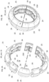
- the core 10 comprises, as is notably visible on the Figures 4A, 4C , 5A, 5C , 6A and 6C and 23, an assembly of several annular sub-assemblies 21, 22, 23 comprising: i) a first annular sub-assembly 21 called the “central crown” 21, which forms a central portion of the top zone 11 of the receiving surface 10_out, a central portion of the top zone 11 which is intended to receive one or more components constituting the crown 3 of the tire 2, ii) a second annular sub-assembly 22 called the “left ear” 22, which is axially attached to the central crown 21, said left ear 22 comprising the first lateral zone 12 of the receiving surface 10_out as well as a portion of the top zone 11 which axially extends the central portion of the top zone 11 on the corresponding side of
- the left ear 22, the central crown 21, and the right ear 23 are coaxial, and centered on the central axis Z10.
- the central crown 21 is devoid of passages 15 for stays 16, and can thus preferentially have a solid external surface, which forms an annular central island separating the respective grooves 15 of the left lug 22 and the right lug 23.
- a solid external surface which forms an annular central island separating the respective grooves 15 of the left lug 22 and the right lug 23.
- such an arrangement will facilitate demolding, and will also make it possible to locally pass the stays 16 on the outside of the central crown 21, and therefore on the radially external side of the core 10, on the receiving surface 10_out which will receive the components of the wall 8 of the bandage, which will make it possible to easily integrate the corresponding portion of the stays 16 into the wall 8 and therefore to ensure the anchoring of said stays in the top 3 of the bandage 2.
- the top portion of the central crown 21 forms a right cylinder, with a circular base, centered on the central axis Z10.
- the equatorial plane P_EQ is contained in the axial range covered by the central portion of the summit zone 11 of the central crown 21, and more particularly is located in the middle of said axial range, so as to subdivide the central portion of the summit zone 11, and more generally the central crown 21, into two parts which are equal, or even symmetrical to each other, with respect to said equatorial plane P_EQ.
- the ears 22, 23 have, in section in a radial plane, a curved, convex external profile, which ensures a curved transition between the top zone 11 and the corresponding lateral zone 12, 13 of the receiving surface 10_out, and the curvature of which matches the curvature of the hollow of the cavity 9 of the bandage 2, and more particularly the curvature of the internal surface 8_in of the wall 8 of the bandage at the transition between the top 3 and the sidewall 6, 7, as well as in the zones where the wall 8 forms the axially outermost points of the sides 6, 7.
- the ear 22, 23 forms a lobe which can occupy, temporarily fill and therefore conform, the hollow of the cavity 9 of the bandage 2, during the manufacture of said bandage 2.
- the ears 22, 23, as well as the central crown 21, will preferably be reusable from one manufacturing cycle to another, and for this purpose made of a durable material, such as an aluminum alloy.
- an arrangement of the tool 1 will be provided which will be adapted to the disassembly of the core 10, and more particularly to the disassembly of the sub-assemblies 21, 22, 23, from the inside of the bandage 2.
- said annular subassemblies 21, 22, 23, namely the central crown 21, the left ear 22, and the right ear 23, are each angularly divided into sectors 24, 25, 26, 27, 28, 29, in azimuth around the central axis Z10, according to an alternation of sectors called "keys" 24, 26, 28, designed to be accessible by radially internal approach and to be removed first during the disassembly of the subassembly 21, 22, 23 considered, and of sectors called "vaults" 25, 27, 29, supported and locked in position by the keys 24, 26, 28, and designed to become maneuverable after they have been released by the removal of the keys 24, 26, 28.
- the central crown 21 is subdivided into a plurality of crown keys 24 and crown vaults 25.
- the number of crown keys 24, equal to the number of crown vaults 25, will be chosen to be sufficiently high to allow easy splitting and disassembly by centripetal radial extraction of the sectors 24, 25 constituting the central crown 21, and nevertheless sufficiently moderate so as not to unnecessarily multiply the sectors 24, 25, and therefore to simplify the assembly of the subassembly 21 forming the central crown 21.
- the number of crown keys 24, and therefore the number of crown vaults 25, will preferably be between 4 and 6, and more preferably equal to 5, as is the case on the Figures 3A and 3B .
- crown keys 24 will preferably be identical to each other, and therefore interchangeable.
- crown vaults 25 will preferably be identical to each other, and therefore interchangeable.
- the lateral faces which delimit each crown key 24 and which form the joint planes of said crown key 24 with the two crown vaults 25 adjacent to said crown key 24, will be parallel to each other and parallel to the sagittal meridian plane of the crown key 24 considered.
- said lateral faces will each form a non-zero clearance angle, preferably between 1 and 2 degrees, for example equal to 1.5 degrees, relative to said sagittal meridian plane, so that said two lateral faces form intersecting planes which widen, that is to say which move away obliquely from each other, and which each move away from the sagittal meridian plane, as one approaches radially the central axis Z10, said intersecting planes forming between them an opening angle which is equal to the sum of the respective clearance angles of said lateral faces, here for example an opening angle of 3 degrees if each face has a clearance angle of 1.5 degrees.
- the crown vaults 25 will of course form sectors complementary to the crown keys 24, and will be locked in position by said crown keys 24 within the annular subassembly 21 forming the central crown 21.
- the crown keys 24, moreover positioned and maintained by a common support (not shown), will therefore prevent the collapse of the crown vaults 25, and more generally of the arch formed by the succession of said keys 24 and vaults 25.
- This support provided by the crown keys 24 will be all the more robust and stable as the clearance angle of the lateral faces of the crown keys 24 is high.
- the central crown 21 will preferably comprise, on either side of the central portion of the summit zone 11, a first relief face 32 supporting the left ear 22, and a second relief face 33 supporting the right ear 23.
- Said first and second relief faces 32, 33 will preferably form respectively a first chamfer 32 and a second chamfer 33, which are radially closer to the central axis Z10 than the passages 15 intended for the stays 16 and which form, with the central portion of the summit zone 11, a convex profile, in section in a radial plane containing the central axis Z10, as can be seen on the Figures 4C , 5C , 6C And 24 .
- the central crown 21 is contained in a space which is radially set back from the stays 16, and set back from the lugs 22, 23, and the sectors 24, 25 of said central crown 21 will be able to carry out, after curing of the bandage 2, and while the lugs 22, 23 are still captive in said bandage 2, a centripetal radial extraction movement without interfering with the lugs 22, 23 still in place in the cavity of the bandage 2.
- said ear sectors 26, 27, 28, 29 will each cover a relatively restricted angular sector around the central axis Z10, but nevertheless sufficiently large to limit the number of ear sectors 26, 27, 28, 29 to be assembled to produce each ear 22, 23.
- each ear key 26, 28 of an ear 22, 23 occupies an angular sector A26 whose value will be an integer divisor of 360 degrees, and preferably whose value is equal to that of the angular sectors occupied by the other keys 26, 28 of the same ear.
- each arch 27, 29 of an ear 22, 23 will preferably occupy an angular sector A27 whose value will be an integer divisor of 360 degrees, and preferably whose value is equal to that of the angular sectors occupied by the other arches 27, 29 of the same ear 22, 23.
- the angular sector A26 covered by each ear key 26, 28, considered relative to the central axis Z10 and at the radially outermost level of the receiving surface 10_out of the ear key 26, 28 concerned, as is notably visible on the Figure 10 will preferably be equal to or greater than 9 degrees, and preferably less than or equal to 36 degrees, and more preferably equal to or less than 24 degrees, and even more preferably equal to or less than 18 degrees.
- an angular sector A26 equal to 9 degrees, 15 degrees, 18 degrees, or even 24 degrees, the value of 9 degrees being preferred however in view of the dimensions of the bandages 2 envisaged, and more particularly in view of the corresponding maximum diameter of the receiving surface 10_out, as well as in view of the chosen angular repetition pitch P16 (here preferably 1.5 degrees).
- each ear vault 27, 29, at the maximum diameter of the receiving surface 10_out will preferably be equal to or greater than 9 degrees, and preferably less than or equal to 36 degrees, and more preferably equal to or less than 24 degrees, and even more preferably equal to or less than 18 degrees, and for example chosen from 24 degrees, 18 degrees, 15 degrees or, more preferably, 9 degrees.
- the sectoral division of the left ear 22 will be identical, and will coincide in azimuth, with the sectoral division of the right ear 23, so that each key 26 of the left ear 22 will be located opposite a key 28 of the right ear 23, and will be angularly superimposed on the latter in projection in the plane equatorial P_EQ, and, similarly, each vault 27 of the left ear 22 will be located opposite, and angularly superimposed on, the corresponding vault 29 of the right ear 23.
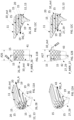
- grooves 15 there will preferably be between 5 and 23 grooves 15 per ear key 26, 28, preferably between 5 and 9 grooves per ear key 24, and more preferably 7 grooves per ear key 26, 28 as illustrated in the Figures 7B , 9B and 10 .
- the corresponding ear arches 27, 29 may preferably have between 3 and 21 grooves 15, preferably between 3 and 7 grooves 15, and for example 5 grooves 15 as illustrated in the Figures 8B And 10 .
- ear keys 26 each occupying an angular sector A26 with a value of 9 degrees and each provided with seven grooves carried by radial planes
- conjugate ear vaults 27 each occupying an angular sector A27 with a value of 9 degrees and each provided with five grooves carried by radial planes are used.
- flanks 40, 41 of the ear keys 26 are parallel to each other, and parallel to the sagittal meridian plane P_MER_26 of each ear key 26 concerned, while the flanks 42, 43 of the ear vaults 27 form an angle of 18 degrees between them, and each of 9 degrees relative to the sagittal meridian plane P_MER_27 of the ear vault 27 concerned.
- each sector has three starting points for grooves 15 inclined to the left (i.e. counterclockwise) in projection in a plane normal to the central axis Z10 and three starting points for grooves inclined to the right (i.e. clockwise) in projection in said plane normal to the central axis Z10.
- the ear keys 26, 28 will be identical and interchangeable at least within the same ear 22, or even interchangeable from one ear 22 to the other ear 23.
- the ear arches 27, 29 will preferably be identical and interchangeable at least within the same ear 22, or even interchangeable from one ear 22 to the other ear 23.
- the ear vaults 27, 29, and more preferably only the ear vaults 27, 29 (and not the ear keys 26, 28), will be fixed on the central crown 21, and more particularly on the relief faces 32, 33, by means of screws, screws which are engaged radially centrifugally from the empty interior space of the central crown 21, to engage on the radially internal face of said ear vaults 27, 29, and the passage holes 34 of which are seen through the central crown 21 on the Figures 3A, 3B , 4A, 4C , 5A, 5C , 6A, 6C .
- the ear keys 26, 28 may cooperate with the ear arches 27, 29, and thus be positioned and retained, by means of pins, engaged in pin holes 35 provided in the keys 26, 28, as visible on the Figures 7A , 9A , 11A , and which engage in corresponding housings 36 provided in the ear vaults 27, 29, as illustrated in the Figures 8A Or 21B .
- the ear keys 26, 28 may be provided with projecting tenons 37, as visible on the Figures 13A, 13D , 15A, 15C , intended to cooperate with mortises 38 provided in the ear vaults 27, 29, as can be seen on the Figure 14A .
- the ear sectors 26, 27, 28, 29, both the ear keys 26, 28 and the ear arches 27, 29, will be made of a metal alloy, more preferably of an aluminum alloy, in order to have good rigidity, and a good heat conduction capacity, with a relatively low thermal inertia.
- a metal alloy more preferably of an aluminum alloy
- the ear sectors 26, 27, 28, 29 will be produced by additive manufacturing, which will simplify the manufacturing of relatively complex geometries.
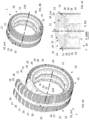
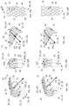
- the flanks 40, 41 of at least one ear key 26, 28 which delimit the angular sector A26 occupied in azimuth by said ear key 26, 28 around the central axis Z10 and which thus form the joint planes PJ according to which said ear key 26, 28 cooperates with the ear vaults 27, 29 adjacent to said ear key 26, 28 within the annular subassembly 22, 23, that is to say within the ear 22, 23 corresponding to the assembled state, are parallel to a fictitious plane called the “sagittal meridian plane” P_MER_26, which corresponds to the radial plane which contains the central axis Z10 and which intersects the angular sector A26 occupied by the ear key 26, 28 considered in its middle, as can be seen 7B, 9B, 10 and 11B, so that said flanks 40, 41 allow extraction of the ear key 26, 28 from the ear vaults 27, 29 which are adjacent to it by sliding and/or tilting along said joint planes PJ, as illustrated in Figures 20
- the sagittal meridian plane P_MER_26 subdivides the arc which marks the outermost radial limit of the ear key 26, 28 considered, and therefore the arc which corresponds, in projection in a plane normal to the central axis Z10, to the radially outermost limit of the portion of the receiving surface 10_out belonging to said ear key 26, 28, into two equal half-arcs, carried by adjacent angular half-sectors of the same azimuthal angular coverage equal to A26/2.
- flanks 42, 43 of the ear vaults 27, 29 are preferably formed by planes which are oriented, on either side of the sagittal meridian plane P_MER_27 of the vault 27, 29 concerned, in directions combined with those of the flanks 40, 41 of the ear keys 26, 28.
- the ear keys 26, 28 and the ear arches 27, 29 are butted against each other in plane support, which gives the ear keys 26, 28 three potential degrees of freedom relative to the ear arches 27, 29, namely two degrees of freedom in translation along two intersecting directions defining the joint planes PJ, here typically the axial direction and the radial direction, and one degree of freedom in rotation about an axis normal to the joint planes PJ, here therefore about an axis corresponding to the direction vector of the circumferential direction, said degree of freedom in rotation making it possible to tilt the key in pitch as illustrated in the figures 20D, 20E , 21B and 21C .
- ear keys 26, 28 with flat and parallel sides 40, 41 can be implemented equally well with grooves 15 arranged according to radial planes ( Figures 7A, 7B, 7C , 9A, 9B, 9C, 10 And 23 ), in which case the sagittal meridian plane P_MER_26 of the ear key 26, 28 preferably coincides with the sagittal meridian plane of a groove 15, than with intersecting oblique grooves 15 ( figures 11A, 11B, 11C ), provided that the grooves 15 are hollowed out in a suitable shape.
- the grooves 15 of the same ear sector 26, 27, 28, 29 are each delimited by two lateral walls which are generated by following an axial generating direction DG_A which is vectorially collinear, that is to say parallel, to the central axis Z10, as is the case on the variants of the Figures 7A, 8A , 9A and 10 comprising grooves 15 carried by radial planes, but also on the variant of the Figures 11A and 12A comprising intersecting inclined grooves 15.
- the grooves 15 of the same ear sector 26, 27, 28, 29 are each delimited by two lateral walls which form relief faces which widen from the bottom 19 of the groove 15 to the receiving surface 10_out so as to clear, throughout the interior of the groove 15 concerned, a free space which contains a fictitious volume, called the “necessary template volume”, generated by executing a virtual scan of the stay 16 concerned along a virtual exit trajectory, here from the location of said stay 16 close to the bottom 19 of the groove 15 to the receiving surface 10_out, carried by an axial generating direction DG_A which is vectorially collinear, i.e. parallel to the central axis Z10.
- such an arrangement of the side walls means that said grooves 15 allow axial extraction of the ear sector 26, 27, 28, 29 concerned, according to an axial extraction movement M_A which is parallel to the central axis Z10 and directed towards the equatorial plane P_EQ of the core 10, as illustrated in the figures 20B, 20C , And 21A , without the side walls of said grooves 15 interfering with the stays 16 during said axial extraction movement M_A.
- the stays 16 sweep, by definition, a volume corresponding to the aforementioned necessary template volume, a volume whose lateral limits define the edges, rectilinear and parallel to the axial generating direction DG_A, of an envelope inside which the blocks of material delimiting the grooves 15 must not penetrate so as not to hinder the extraction.
- the width W15 of said grooves which corresponds to the distance which separates the two side walls delimiting the groove 15 considered, will have the proportions and/or dimensions mentioned above, and in particular may therefore be between 0.1 mm and 3 mm.
- the intersecting grooves 15 of the same ear sector 26, 27, 28, 29 may each be delimited by two lateral walls which are generated by following an oblique generating direction DG_O, as is the case on the Figures 13A to 13D, 14A to 14D , 15A to 15C , 17, 18A, 19 And 22A to 22C , oblique generating direction DG_O which is contained in the radial plane which intersects the ear sector 26, 27, 28, 29 considered in its middle, called the “sagittal meridian plane” P_MER_26, P_MER_27, and which, in said sagittal meridian plane P_MER_26, P_MER_27, converges towards the central axis Z10 in the direction going from the ear 22, 23 concerned towards the opposite ear 23, 22, and forms with the central axis Z
- the oblique generating direction DG_O thus “dips” towards the equatorial plane P_EQ, and towards the opposite ear 23, 22, and will therefore allow extraction of the ear sector 26, 27, 28, 29 concerned according to an oblique extraction movement M_O, which will be directed towards the interior of the core 10, and which will simultaneously comprise an axial component and a radial component.
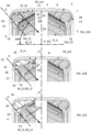
- the absolute value of the colatitude angle A44 will be chosen equal to or less than the angle formed, in the sagittal meridian plane P_MER_26, P_MER_27, by the tangent T4 to the internal surface 8_in of the wall 8 of the tire 2 at the level of the bead 4, considered at the point where said bead 4 forms the most marked undercut, so that the orientation of said tangent T4 relative to the central axis Z10 defines the “moldability threshold”, that is to say the maximum colatitude angle that the oblique extraction movement M_O can have to demold the ear sector 26, 27 concerned by sliding along the internal surface of the bead 4 without being blocked by said bead 4, and therefore without forcing a separation (an opening) of the bead 4 and the corresponding flank 6 of the tire 2 during the demolding operation, as illustrated in the figures 22A, 22B, 22C .
- the considerations applicable to the left ear 22 will be adaptable mutatis
- the flanks 40, 41, and therefore the joint planes PJ, which delimit the ear key 26, 28 concerned can preferably be generated by following the oblique generating direction DG_O from a base profile 45 which corresponds i) either, according to a first possibility, to the intersection 46 of the receiving surface 10_out with a radial plane P1, P2 which is angularly offset in azimuth relative to the sagittal meridian plane P_MER_26 of said ear key 26, 28 by a value such that the base profile 45 passes through the opposite vertices of the grid patterns (i.e.
- the bases of the aforementioned prisms 20 here therefore through the opposite vertices of the quadrilaterals, which are defined on the receiving surface 10_out by the intersecting grooves 15 and which follow one another from the top zone 11 to the lateral zone 12, 13 along said base profile 45, as can be seen on the figures 13B, 13D, 14B, 14D , 15A, 16B And 17 , ii) or, according to a second possibility, to the broken zigzag line 47 formed, on the receiving surface 10_out, by the alternation of the sides of the grid patterns (the bases of the aforementioned prisms 20), here therefore by the alternation of the sides of the quadrilaterals, which are defined on the receiving surface by the intersecting grooves 15 and which follow one another from the summit zone 11 to the lateral zone 12, 13, as illustrated in the Figures 18A, 18B and 19 .
- such a choice of the basic profile 45 advantageously makes it possible to avoid or greatly limit the “aberrations”, that is to say the offsets, at the level of the joint planes PJ, between the grooves 15 belonging to the ear key 26, 28 located on one side of said joint plane PJ and the grooves 15 belonging to the ear arch 27, 29 attached to said ear key and located on the other side of said joint plane PJ.
- the solution consisting of opting for a basic profile 45 which follows a broken line 47 forming alternately re-entrant angles and salient angles, along the walls defined by the successive prisms 20 (as illustrated in dotted lines on the figures 18A, 18B, 19 ), is generally satisfactory and allows robust and precise fitting of the ear keys 26, 28 into the ear arches 27, 29, but has the disadvantage of creating zebra stripes which tend to locally widen certain grooves 15 at the level of the receiving surface 10_out, along the joint planes PJ, as can be seen on the figure 19 .
- the first solution may be preferred, according to which the basic profile 45 is the curve 46 drawn on the receiving surface 10_out by the intersection of the radial planes P1, P2 with said receiving surface 10_out and which passes through the vertices of the quadrilaterals, along a diagonal common to the successive quadrilaterals, as illustrated in the figures 13A, 13B, 13D, 14D , 15A And 17 .
- such a solution advantageously makes it possible to make the nodes of the network of quadrilaterals defined by the intersecting grooves (that is to say the nodes formed by the intersections between two grooves) coincide, and more generally the nodes of the network of prisms 20, belonging to the ear key 26 considered with the nodes of the network of quadrilaterals belonging to the corresponding ear vault 27 located on the other side of the joint plane PJ.
- This guarantees the continuity of the grooves 15 at the level of their connection between successive ear sectors, without significantly altering the width W15 of said grooves 15.
- the value of the angular coverage A26 being a multiple (integer) of the repetition pitch P16 of the grooves 15, it is possible to place each radial plane P1, P2 at the right of the nodes formed by the vertices of the quadrilaterals drawn by the intersecting grooves 15.
- the core 10 can preferably have, on the back of said side walls, under the receiving surface 10_out, and penetrating between the passages 15, recesses 50 which are distinct from the passages 15 and separated from said passages 15 by the side walls, as illustrated in the Figures 15B and 15C .
- Said recesses preferably extend to a depth, below the receiving surface 10_out, which is less than the hollow depth of the passages 15 bordering the recesses, i.e. which is less than the depth of the bottom 19 of the grooves 15, so that the core 10 has a thinner skin at the level of the recesses 50 than at the level of the side walls of the passages 15.
- Such recesses 50 make it possible to give the ears 22, 23 a structure which is light and, above all, which has low thermal inertia, and which therefore optimizes the transmission of heat from the central crown 21, which preferably contains heating elements such as electric heating resistors.
- the tool 1 may comprise an anti-penetration device 60 which cooperates with the core 10 to prevent penetration of the constituent components of the crown 3, the sides 6, 7 or the beads 4, 5 of the bandage 2 into the passages 15 of the core 10 in which the stays 16 are engaged.
- the anti-penetration device 60 prevents the materials, and in particular the rubber-based compositions, present in the components of the bandage 2 from penetrating into the grooves 15 by creep, in order to prevent the formation of rubber burrs which would cause the stays 16 to stick to the walls of the grooves 15, and which would therefore create a risk of the stays 16 being torn off when the corresponding ear sectors 26, 27, 28, 29 are extracted.
- the anti-penetration device 60 may comprise masking elements 61, 62, intended to form a screen, at the receiving surface 10_out, between the components of the wall 8 of the bandage and the openings of the passages 15 for stays, here the openings of the grooves 15.
- the masking elements 61 will of course be chosen so as to be compatible with the high temperature values (typically more than 100°C) and pressure (typically more than 60 bars) to which the core 10 and the bandage 2 are exposed during the baking operation.
- flexible tape such as metal tape, made of steel for example, held by an adhesive, for example by adhesive tape, flexible tape which will be applied to the receiving surface 10_out, after placing the stays 16 in the grooves 15, in order to cover the grooves 15.
- the masking elements will comprise reusable shells 61, for example made of polymer or preferably metal.
- Said shells 61 will preferably have a curved C-shape so that each of said shells 61 can, preferably in one piece, continuously cover the openings of the grooves 15 from the lateral zone 12, 13 to the top zone 11, matching the bulge of the core 10, here the bulge of the ears 22, 23, as can be seen on the Figures 6A, 6B, 6C , 20A , 21A .
- the ear sectors 26, 27, 28, 29 may comprise an imprint 62 in which the corresponding shell 61 fits and is advantageously positioned and held by one or more shoulders.
- the depth of said imprint 62 will preferably be such that the radially external surface of the shell 61 is flush with the neighboring receiving surface 10_out.
- each shell 61 will be provided for each ear sector 26, 27, 28, 29, and each shell 61 will cover an angular sector A26, A27 identical to that of the ear key 26, 28, respectively of the ear vault 27, 29 that said shell 61 covers, as is clearly visible in the Figure 6A .
- all the shells 61 will be identical to each other and therefore interchangeable with each other, at least within the same ear 22, and preferably between the two ears 22, 23.
- the masking elements may also comprise, preferably in addition to the shells 61, masking strips 63, formed by ribbons, preferably made of metal, of the sheet type, which may contribute to masking the openings of the grooves in the top zone 11 of the receiving surface 10_out, preferably by partially overlapping the shells 61, as is illustrated in particular in the Figures 6A, 6B, 6C
- the overlap may extend axially over a few millimeters, for example 3 mm to 15 mm.
- the division of the masking screen into shells 61 and masking strips 63 helps to facilitate demolding, and more particularly the extraction of the shells 61 and the strips 63 from the inside of the bandage, between the shrouds 16.
- the overlap between the shell 61 and the strip 63 advantageously makes it possible to avoid creating a leak gap between these two masking elements.
- the tool 1 will comprise two sets of shells 61, one on each side of the equatorial plane P_EQ, and two strips 63 each making a complete turn around the central axis Z10 and each located on one side of the equatorial plane P_EQ, as can be seen in the Figures 6A, 6B, 6C .
- the strips 63 will each be interrupted axially set back from the equatorial plane P_EQ, so as to leave visible the portion of the summit zone 11 formed by the central crown 21, and at the level of which the summit anchoring point 17 will be formed.
- the anti-penetration device 60 may comprise filling elements 65 designed to fill and thus substantially close the interstitial space which remains vacant within the passages 15 after the stays 16 have been put in place in said passages 15.
- the filling elements 65 may occupy the free space which is included between the side walls of the grooves 15, the stay 16 contained in the groove considered, and the opening of said groove considered at the receiving surface 10_out.
- Any suitable substance capable of insinuating itself into the passages 15 and sufficiently dense to prevent, or significantly slow down, the penetration into the groove 15 of the constituent materials of the components of the bandage, and in particular of the mixtures based on unvulcanized rubber, may be used as a filling element 65.
- the filling elements may be formed by rigid wedges 65, preferably metallic, of a shape substantially matching the cavities of the grooves 15, and which will be inserted into said grooves 15 after having previously engaged the stays 16 in said grooves.
- the invention also relates to a method of manufacturing a bandage 2 braced on a core 10.
- such a method preferably involves using a tool 1 as described above.
- the invention also relates to a method for manufacturing a toroidal bandage 2 comprising a crown 3 intended to form a tread, a first annular bead 4 and a second annular bead 5 designed to allow the bandage to be attached to a mounting support such as a rim, as well as a first sidewall 6 and a second sidewall 7 which connect the crown 3 respectively to the first bead 4 and to the second bead 5, the crown 3, the first and second sidewalls 6, 7 and the first and second beads 4, 5 forming as a whole a wall 8 having a concave internal surface 8_in which delimits a cavity 9 of the bandage 2, said bandage 2 comprising reinforcing elements 16, called “stays” 16, which each extend into the cavity 9 of the bandage by connecting a top anchoring point 17 located in the top 3 of the bandage to a lateral anchoring point 18 located in one of the sides 6, 7 or the beads 4, 5 of the bandage.
- a mounting support such as a rim
- Said method comprises a preparation step (S0), during which a tool 1 according to the invention is prepared.
- the crown keys 24 and crown vaults 25 will be assembled to form the central crown 21, as illustrated in the Figures 3A and 3B , then we will fix, on each of the relief faces 32, 33 of said central crown 21 a succession of ear keys 26, 28 and ear vaults 27, 29 to form the ears 22, 23, as illustrated in particular on the Figures 4A to 4C , And 5A to 5C .
- the method then comprises a step (S2) of installing stays 16, during which at least one reinforcing wire 70, intended to form a stay 16, is passed through each passage 15 of the core 10.
- a single continuous reinforcing wire 70 is used to form several stays 16, preferably more than 25%, more than 50%, or even the entire number of stays 16 of the bandage 2.
- the reinforcing wire 70 is preferably arranged continuously in a serpentine fashion through the successive passages 15, here by inserting said reinforcing wire 70 into the grooves 15, under the receiving surface 10_out, and by bringing out said reinforcing wire 70 above the receiving surface 10_out in the top zone 11 and in the lateral zones 12, 13, at the desired anchoring points 17, 18, as can be seen in the figure 24 , thereby making said continuous reinforcing wire 70 go and return in one piece from one lateral zone 12 of the core 10 to the other lateral zone 13 via the top zone 11, as can be seen in the figure 25 , so as to form undulations, here of amplitude substantially symmetrical with respect to the equatorial plane P_EQ.
- the method then comprises a filling step (S4) during which the constituent components of the crown 3, the sides 6, 7 and the beads 4, 5 of the bandage are deposited on the receiving surface 10_out, in order to construct the wall 8 of the bandage 2.
- Said components will preferably comprise rubber-based strips or sheets, possibly reinforced by longitudinal reinforcing threads, made of textile, polymer, or metal.
- Other reinforcing components may be provided, such as composite strips based on fiberglass and resin.
- All or part of said components may preferably be placed by winding on the rotating core 10.
- the method then comprises a cooking step (S5).
- the core 10 and the bandage 2 carried by said core 10 are placed in a baking mold, in order to vulcanize the rubber-based components of the bandage 2.
- the temperature of the mold, and more particularly of the bandage will preferably be brought to a value between 120°C and 200°C.
- the method then comprises a demolding step (S6) during which the core 10 is released from the bandage 2 while leaving the stays 16 in place in the cavity 9 of said bandage 2, as is notably illustrated in the sequences of Figures 20A to 20F , 21A to 21C , And 22A to 22C .
- a part of the core 10, for example the ears 22, 23, is for single use, it can be destroyed by the appropriate process (melting, dissolution, disintegration, shock, sublimation, etc.) to release the cavity 9 and the stays 16.
- the core 10 is reusable, and therefore formed from a modular assembly of removable parts, the said parts will be dismantled and gradually extracted to release the bandage 2.
- said method comprises a pre-filling step (S1) during which, as illustrated in the figure 24 , anchoring structures 71, 72 are placed on the lateral zones 12, 13 and on the top zone 11 of the receiving surface 10_out of the core 10, opposite the anchoring points 18, 17 provided for attaching the stays 16 to the wall 8 of the bandage, which are designed to collect the ends of the stays 16 which emerge passages 15 of the core 10 and to adhere to the constituent components of the sides 6, 7 or the beads 4, 5, respectively to the constituent components of the top 3, by sandwiching said ends of the stays 16 between the anchoring structures 71, 72 and said components, in order to ensure the fixing of the stays 16 to the anchoring points 18, 17 provided.
- the anchoring structures 71, 72 will be formed from unvulcanized rubber-based material, possibly reinforced by means of reinforcing threads or fibers.
- the anchoring structures 71, 72 may, for example, take the form of reinforcing strips or turns wound on the core 10.
- the anchoring structures 71, 72 being positioned in standby on the receiving face 10_out, outside the grooved portions, at the desired anchoring points 18, 17, the stays 16 will be put in place in the passages by ensuring that the portions of said stays 16 which emerge from the passages 15 come to be positioned over said anchoring structures 71, 72, so that when the components of the wall 8 of the bandage are then placed, said components adhere to the anchoring structures already in place on the core 10, and said anchoring structures 71, 72 therefore integrate the wall 8 of the bandage 2, thus pinching the ends of the stays 16 inside the wall 8, at the level of the anchoring points 18, 17 provided.
- the loops forming the extrema of the undulations of the continuous coil of reinforcing wire 70 which therefore correspond to the transition zones between two successive stays belonging to the same hemisphere, which form the portions of the stays 16 which will be captive to the lateral anchoring structures 71 placed on the lateral zones 12, 13, to form the lateral anchoring points 18 of the stays, while the intermediate portions of the continuous reinforcing wire 70 which connect two successive stays 16 belonging to two different hemispheres, emerging from the groove 15 of the first stay in order to travel through the top zone 11 of the receiving surface 10_out and cross the equatorial plane P_EQ then plunge back into the groove 15 of the second stay 16, will be captive to the top anchoring structure 72.
- the method comprises a protection step (S3), during which an anti-penetration device 60 is implemented which, during the filling step (S4) and during the baking step (S5), cooperates with the core 10 to prevent penetration of the components constituting the top 3, the sides 6, 7 or the beads 4, 5 of the bandage 2 in the passages 15 of the core 10, here in the grooves 15, in which the stays 16 are engaged.
- a protection step (S3) during which an anti-penetration device 60 is implemented which, during the filling step (S4) and during the baking step (S5), cooperates with the core 10 to prevent penetration of the components constituting the top 3, the sides 6, 7 or the beads 4, 5 of the bandage 2 in the passages 15 of the core 10, here in the grooves 15, in which the stays 16 are engaged.
- masking elements such as shells 61 and/or masking strips 63, as described above, which cover the passages 15 and thus act as a screen between said passages 15 and the components of the wall 8 of the tire, as illustrated in the Figures 6A and 6B , or by using a filling element 65, such as a shim 65 ( figure 23 ), which temporarily fills, at least during the cooking step (S5), or even also during the filling step (S4), the volume of each passage 15 which is left free between the stay 16 engaged in said passage 15 and the opening(s) of said passage 15 which open onto the receiving surface 10_out.
- a filling element 65 such as a shim 65 ( figure 23 )
- the core 10 comprising on the one hand a central crown 21, and on the other hand a left ear 22 and a right ear 23 containing the passages 15 of stays 16 in the form of grooves 15 which are open on the receiving surface 10_out, each of said central crown 21 and ears 22, 23 being angularly divided into sectors forming keys 24, 26, 28 alternating with vaults 25, 27, 29, as described above, the demolding step (S6) firstly comprises a first sub-step of removing the central crown 21, during which the keys 24 are radially removed from the central crown, then the vaults 25 from the central crown, in order to release the ears 22, 23, and so that we are therefore in a configuration in which the sectors 26, 27, 28, 29 of the ears 22, 23 are accessible from the inside of the bandage 2 as illustrated in the figures 20A And 22A , then a second sub-step of extracting a first lug 22 during which the keys 26 of one 22 of the left and right lugs are extracted from the cavity 9 of the bandage 2, then the arches 27 of said lug 22 are
- the order of extraction of the sectors of the ears 22, 23 may possibly be slightly adapted, the only necessity being, within a given ear, to first extract the two ear keys 26, 28 which border an ear vault 27, 29 before being able to extract in turn said ear vault 27, 29.
- the extraction in axial translation M_A is in particular necessary to allow the earlobe 22, 23 to be sufficiently freed from the hollow of the cavity 9, and in particular from the internal edge of the bead A, 5, so that it is then possible to execute the pitching tilting movement M_B without forcing the bead 4, 5 to move away from the top 3, and therefore without forcing the stays 16.
- the extraction sequence of said ear sector 26, 27, 28, 29 can be completed freely from the inside of the bandage 2, for example by following, as illustrated in the Figure 20F , a radial movement which brings the sector 26, 27, 28, 29 concerned closer to the central axis Z10, to radially cross the threshold formed by the bead 4, 5, followed by an axial movement which causes said sector 26, 27, 28, 29 to completely exit from the envelope which axially delimits the bandage 2.
- the corresponding shells 61 can be extracted in turn, individually, by rotation and tilting in order to slide said shells 61 edgewise between two shrouds 16 (a branch of the shell after the other).
- the masking strips 63 can be extracted by a spiral sliding which makes them pass into the space between two successive stays 16.
Landscapes
- Engineering & Computer Science (AREA)
- Mechanical Engineering (AREA)
- Tyre Moulding (AREA)
- Tires In General (AREA)
- Moulds For Moulding Plastics Or The Like (AREA)
- Prostheses (AREA)
Claims (15)
- Werkzeug (1) zur Herstellung eines toroidalen Reifens (2) mit einem Scheitel (3), der dazu bestimmt ist, einen Laufstreifen zu bilden, einem ersten ringförmigen Wulst (4) und einem zweiten ringförmigen Wulst (5), die dazu bestimmt sind, das Einhaken des Reifens (2) auf einem Montageträger wie einer Felge zu ermöglichen, sowie einer ersten Flanke (6) und einer zweiten Flanke (7), die den Scheitel (3) jeweils mit dem ersten Wulst (4) und dem zweiten Wulst (5) verbinden, wobei der Scheitel (3), die erste und zweite Flanke (6, 7) und der erste und zweite Wulst (4, 5) in ihrer Gesamtheit eine Wand (8) mit einer konkaven Innenfläche (8_in) bilden, die einen Hohlraum (9) des Reifens (2) begrenzt, wobei das Werkzeug (1) einen ringförmigen Kern (10) aufweist, der um seine zentrale Achse (Z10) eine konvexe Außenfläche, genannt "Aufnahmefläche" (10_out), aufweist, die eine zur Innenfläche (8_in) der Wand (8) des Reifens konjugierte Form besitzt und die zu diesem Zweck einen radial äußeren Scheitelbereich (11) aufweist, der dazu bestimmt ist, Komponenten aufzunehmen, die den Scheitel (3) des Reifens (2) bilden, und zu beiden Seiten axial des Scheitelbereichs (11) einen ersten Seitenbereich (12), der zur zentralen Achse (Z10) hin umgeschlagen ist und dazu bestimmt ist, die Bestandteile aufzunehmen, die die erste Flanke (6) und den ersten Wulst (4) bilden, sowie einen zweiten Seitenbereich (13), der zur Mittelachse (Z10) hin umgeschlagen ist und dazu bestimmt ist, die Bestandteile aufzunehmen, die die zweite Flanke (7) und den zweiten Wulst (5) bilden, so dass der Kern (10) ein Volumen materialisiert, genannt "reserviertes Volumen", das außen von der Aufnahmefläche (10_out) begrenzt wird und dem Hohlraum (9) des Reifens entspricht, wobei das Werkzeug (1) dadurch gekennzeichnet ist, dass der Kern (10) eine Vielzahl von Durchgängen (15) aufweist, die sich unter der Aufnahmefläche (10_out) innerhalb des reservierten Volumens erstrecken und die sich zu der Aufnahmefläche (10_out) hin öffnen, so dass jeder der Durchgänge (15) den Scheitelbereich (11) der Aufnahmefläche mit einem des ersten und zweiten Seitenbereichs (12, 13) verbindet, so dass der Kern (10) im Inneren der Durchgänge (15) Verstärkungselemente, genannt "Abspannungen" (16), aufnehmen kann, die so gestaltet sind, dass sie die Struktur des Reifens (2) fest integrieren und sich jeweils in den Hohlraum (9) des Reifens erstrecken, indem sie einen im Scheitel (3) des Reifens liegenden Scheitelverankerungspunkt (17) mit einem in einer der Flanken (6, 7) oder der Wülste (4, 5) des Reifens liegenden seitlichen Verankerungspunkt (18) verbinden.
- Werkzeug nach Anspruch 1, dadurch gekennzeichnet, dass die Durchgänge (15) für Abspannungen (16) durch Nuten (15), vorzugsweise Blindnuten, gebildet werden, die von der Aufnahmefläche (10_out) aus in die Dicke des reservierten Volumens gezogen werden, so dass sie eine durchgehende Öffnung entlang des Profils der Aufnahmefläche (10_out) vom Scheitelbereich (11) bis zum betreffenden Seitenbereich (12, 13) aufweisen.
- Werkzeug nach Anspruch 2, dadurch gekennzeichnet, dass der Kern (10) einen Zusammenbau aus mehreren ringförmigen Unterbaugruppen (21, 22, 23) aufweist, die Folgendes aufweisen:i) eine erste ringförmige Unterbaugruppe (21), genannt "zentraler Kranz" (21), die einen zentralen Abschnitt des Scheitelbereichs (11) der Aufnahmefläche (10_out) bildet, die dazu bestimmt ist, eine oder mehrere Komponenten aufzunehmen, die den Scheitel (3) des Reifens (2) bilden, wobei der zentrale Kranz (21) vorzugsweise keine Durchgänge (15) für Abspannungen (16) aufweist,ii) eine zweite ringförmige Unterbaugruppe (22), genannt "linkes Ohr" (22), die axial an den zentralen Kranz (21) angefügt ist, wobei das linke Ohr (22) den ersten Seitenbereich (12) der Aufnahmefläche (10_out) sowie einen Abschnitt des Scheitelbereichs (11) aufweist, der den zentralen Abschnitt des Scheitelbereichs (11) auf der entsprechenden Seite des zentralen Kranzes (21) axial verlängert, und das linke Ohr (22) die Nuten (15) enthält, die die Durchgänge für die Abspannungen (16) bilden, die die erste Flanke (6) des Reifens mit dem Scheitel (3) des Reifens verbinden, undiii) eine dritte ringförmige Unterbaugruppe (23), genannt "rechtes Ohr" (23), die axial an den zentralen Kranz (21) angefügt ist, und zwar auf der Seite des zentralen Kranzes, die der Seite, die das linke Ohr (22) aufnimmt, axial gegenüberliegt, wobei das rechte Ohr (23) den zweiten Seitenbereich (13) der Aufnahmefläche (10_out) sowie einen Abschnitt des Scheitelbereichs (11) aufweist, der den zentralen Abschnitt des Scheitelbereichs (11) auf der entsprechenden Seite des zentralen Kranzes (21) axial verlängert, und das rechte Ohr (23) die Nuten (15) enthält, die die Durchgänge für die Abspannungen (16) bilden, die die zweite Flanke (7) Reifens mit dem Scheitel (3) des Reifens verbinden,und dass die ringförmigen Unterbaugruppen (21, 22, 23), nämlich der zentrale Kranz (21), das linke Ohr (22) und das rechte Ohr (23), jeweils winkelmäßig in Sektoren (24, 25, 26, 27, 28, 29) unterteilt sind, im Azimut um die zentrale Achse (Z10) herum, gemäß einer Abwechslung von Sektoren, genannt "Schlüssel" (24, 26, 28), die so gestaltet sind, dass sie von radial innen zugänglich sind und beim Zerlegen der betrachteten Unterbaugruppe (21, 22, 23) zuerst entfernt werden, und von Sektoren, genannt "Gewölbe" (25, 27, 29), die von den Schlüsseln (24, 26, 28) gestützt und in ihrer Position blockiert werden und so gestaltet sind, dass sie gehandhabt werden können, nachdem sie durch das Zurückziehen der Schlüssel (24, 26, 28) freigegeben wurden.
- Werkzeug nach Anspruch 3, dadurch gekennzeichnet, dass die Flanken (40, 41) mindestens eines Ohrschlüssels (26, 28), die den Winkelsektor (A26) begrenzen, der im Azimut von dem Ohrschlüssel um die zentrale Achse (Z10) eingenommen wird, und die somit die Verbindungsebenen (PJ) bilden, gemäß denen der Ohrschlüssel (26, 28) mit den an den Ohrschlüssel (26, 28) angrenzenden Ohrwölbungen (27, 29) innerhalb der ringförmigen Unterbaugruppen (22) zusammenwirken, parallel zu einer fiktiven Ebene, genannt "sagittale Meridianebene" (P_MER_26), verlaufen, die der radialen Ebene entspricht, welche die zentrale Achse (Z10) enthält und den Winkelsektor (A26), der von dem Ohrschlüssel (26, 28) in seiner Mitte betrachtet eingenommen wird, schneidet, so dass die Flanken (40, 41) ein Entnehmen des Ohrschlüssels (26, 28) aus den an ihn angrenzenden Ohrgewölben (27, 29) durch Gleiten und/oder Kippen entlang der Verbindungsebenen (PJ) erlauben.
- Werkzeug nach einem der Ansprüche 3 und 4, dadurch gekennzeichnet, dass die Nuten (15) desselben Ohrsektors (26, 27, 28, 29) jeweils von zwei Seitenwänden begrenzt werden, die entlang einer axialen Erzeugungsrichtung (DG_A) parallel zur zentralen Achse (Z10) erzeugt werden, oder die Freiflächen bilden, die sich vom Boden (19) der Nut bis zur Aufnahmefläche (10_out) aufweiten, so dass im gesamten Inneren der betreffenden Nut (15) ein Freiraum geschaffen wird, der ein fiktives Volumen, genannt "notwendiges Maßvolumen", enthält, das durch Ausführen einer virtuellen Abtastung der betreffenden Abspannung (16) entlang einer virtuellen Austrittsbahn erzeugt wird, die von einer zur zentralen Achse (Z10) parallelen axialen Erzeugungsrichtung (DG_A) getragen wird, so dass die Nuten (15) ein axiales Entnehmen des betreffenden Ohrsektors (26, 27, 28, 29) gemäß einer axialen Entnahmebewegung (M_A) parallel zur zentralen Achse (Z10) und in Richtung der Äquatorialebene (P_EQ) des Kerns (10) gerichtet erlauben, ohne dass die Seitenwände der Nuten (15) während der axialen Entnahmebewegung (M_A) mit den Abspannungen (16) interferieren.
- Werkzeug nach einem der Ansprüche 2 bis 5, dadurch gekennzeichnet, dass die Nuten (15) entlang radialer Ebenen erzeugt werden, die die zentrale Achse (Z10) enthalten, so dass innerhalb des Reifens (2) Abspannungen (16) angebracht werden können, die sich entlang der radialen Ebenen erstrecken.
- Werkzeug nach einem der Ansprüche 2 bis 5, dadurch gekennzeichnet, dass sich die Nuten (15) so kreuzen, dass sie ein Gitter auf der Aufnahmefläche (10_out) zeichnen, um das Anbringen von gekreuzten Abspannungen (16) innerhalb des Reifens (2) zu ermöglichen.
- Werkzeug nach Anspruch 7 und Anspruch 3, dadurch gekennzeichnet, dass die sich kreuzenden Nuten (15) ein und desselben Ohrsektors (26, 27, 28, 29) jeweils durch zwei Seitenwände begrenzt sind, die entlang einer schrägen Erzeugungsrichtung (DG_O) erzeugt werden, die in der radialen Ebene enthalten ist, die den betreffenden Ohrsektor in seiner Mitte betrachtet schneidet, genannt "sagittale Meridianebene" (P_MER_26, P_MER_27), und die in der sagittalen Meridianebene in Richtung der zentralen Achse (Z10) in der Richtung vom betreffenden Ohr (22, 23) zum gegenüberliegenden Ohr (23, 22) konvergiert und mit der zentralen Achse (Z10) einen Winkel, genannt "Kobreitenwinkel" (A44), bildet, der ungleich Null und strikt kleiner als 90 Grad ist, vorzugsweise zwischen 30 Grad und 50 Grad, beispielsweise zwischen 40 Grad und 47 Grad.
- Werkzeug nach Anspruch 8, dadurch gekennzeichnet, dass die Flanken (40, 41) und damit die Verbindungsebenen (PJ), die den betreffenden Ohrschlüssel (26, 28) begrenzen, entlang der schrägen Erzeugungsrichtung (DG_O) aus einem Basisprofil (45) erzeugt werden, das Folgendem entspricht: i) entweder, gemäß einer ersten Möglichkeit, am Schnittpunkt (46) der Aufnahmefläche (10_out) mit einer radialen Ebene (P1, P2), die im Azimut winkelmäßig gegenüber der sagittalen Meridianebene (P_MER_26) des Ohrschlüssels (26, 28) um einen solchen Betrag versetzt ist, dass das Basisprofil (45) durch die gegenüberliegenden Scheitel der Gittermuster, vorzugsweise Vierecke, verläuft, die auf der Aufnahmefläche durch die sich kreuzenden Nuten (15) definiert sind und die vom Scheitelbereich (11) zum Seitenbereich (12, 13) entlang des Basisprofils (45) aufeinander folgen, ii) oder, gemäß einer zweiten Möglichkeit, an der gebrochenen Zickzacklinie (47), die auf der Aufnahmefläche (10_out) durch die abwechselnden Seiten des Gittermusters, vorzugsweise der Vierecke, gebildet wird, die auf der Aufnahmefläche durch die sich kreuzenden Nuten (15) definiert sind und die vom Scheitelbereich (11) bis zum Seitenbereich (12, 13) aufeinander folgen.
- Werkzeug nach einem der vorhergehenden Ansprüche, dadurch gekennzeichnet, dass die Durchgänge (15) für die Abspannungen (16) durch Seitenwände begrenzt sind und dass der Kern (10) auf der Rückseite der Seitenwände unter der Aufnahmefläche (10_out) und zwischen den Durchgängen (15) eindringend Aussparungen (50) aufweist, die von den Durchgängen (15) verschieden sind und von den Durchgängen (15) durch die Seitenwände getrennt sind.
- Werkzeug nach einem der vorhergehenden Ansprüche, dadurch gekennzeichnet, dass es eine Eindringschutzvorrichtung (60) aufweist, die mit dem Kern (10) zusammenwirkt, um ein Eindringen der Bestandteile, die den Scheitel (3), die Flanken (6, 7) oder die Wülste (4, 5) des Reifens bilden, in die Durchgänge (15) des Kerns (10), in die die Abspannungen (16) eingreifen, zu verhindern.
- Verfahren zur Herstellung eines toroidalen Reifens (2) mit einem Scheitel (3), der dazu bestimmt ist, einen Laufstreifen zu bilden, einem ersten ringförmigen Wulst (4) und einem zweiten ringförmigen Wulst (5), die dazu bestimmt sind, das Einhaken des Reifens (2) auf einem Montageträger wie einer Felge zu ermöglichen, sowie einer ersten Flanke (6) und einer zweiten Flanke (7), die den Scheitel (3) jeweils mit dem ersten Wulst (4) und dem zweiten Wulst (5) verbinden, wobei der Scheitel (3), die erste und zweite Flanke (6, 7) und der erste und zweite Wulst (4, 5) in ihrer Gesamtheit eine Wand (8) mit einer konkaven Innenfläche (8_in) bilden, die einen Hohlraum (9) des Reifens begrenzt, wobei der Reifen (2) Verstärkungselemente (16), genannt "Abspannungen" (16), aufweist, die sich jeweils in den Hohlraum (9) des Reifens erstrecken, indem sie einen im Scheitel (3) des Reifens liegenden Scheitelverankerungspunkt (17) mit einem in einer der Flanken (6, 7) oder der Wülste (4, 5) des Reifens liegenden seitlichen Verankerungspunkt (18) verbinden, wobei das Verfahren einen Vorbereitungsschritt (S0) aufweist, in dessen Verlauf ein Werkzeug (1) nach einem der Ansprüche 1 bis 11 vorbereitet wird, einen Schritt (S2) des Anbringens von Abspannungen (16), in dessen Verlauf ein Verstärkungsdraht (70), der dazu bestimmt ist, eine Abspannung (16) zu bilden, durch jeden Durchgang (15) des Kerns (10) geführt wird, vorzugsweise unter Verwendung eines kontinuierlichen Verstärkungsdrahts (70), der schlangenförmig durch die aufeinanderfolgenden Durchgänge (15) angeordnet werden kann, indem man den kontinuierlichen Verstärkungsdraht (70) in einem Stück von einem Seitenbereich (12) des Kerns (10) über den Scheitelbereich (11) zum anderen Seitenbereich (13) hin und wieder zurücklaufen lässt, dann einen Schritt (S4) des Vorbestückens aufweist, in dessen Verlauf auf der Aufnahmefläche (10_out) die Bestandteile aufgebracht werden, die den Scheitel (3), die Flanken (6, 7) und die Wülste (4, 5) des Reifens bilden, vorzugsweise durch Aufwickeln dieser Bestandteile auf den in Drehung versetzten Kern (10), um die Wand (8) des Reifens (2) aufzubauen, dann einen Schritt (S5) des Aushärtens, dann einen Schritt (S6) des Aus-der-Form-Nehmens, in dessen Verlauf der Kern (10) des Reifens (2) freigelegt wird, wobei die Abspannungen (16) in dem Hohlraum (9) des Reifens (2) an ihrem Platz belassen werden.
- Verfahren nach Anspruch 12, dadurch gekennzeichnet, dass das Verfahren im Anschluss an den Vorbereitungsschritt (S0) und vor dem Schritt (S2) des Anbringens von Abspannungen (16) einen Vorbestückungsschritt (S1) aufweist, in dessen Verlauf auf den Seitenbereichen (12, 13) und auf dem Scheitelbereich (11) der Aufnahmefläche (10_out) des Kerns gegenüber den Verankerungspunkten (18, 17), die zum Befestigen der Abspannungen an der Wand (8) des Reifens vorgesehen sind, folgende Verankerungsstrukturen (71, 72) angebracht werden, die dazu ausgelegt sind, die Enden der Abspannungen (16), die aus den Durchgängen (15) des Kerns herausragen, aufzunehmen und an den Komponenten, die die Flanken (6, 7) oder die Wülste (4, 5) bzw. den Scheitel (3) bilden, anzuhaften, indem die Enden der Abspannungen (16) zwischen den Verankerungsstrukturen (71, 72) und den Komponenten sandwichartig angeordnet werden, um die Befestigung der Abspannungen (16) an den vorgesehenen Verankerungspunkten (18, 17) zu gewährleisten.
- Verfahren nach Anspruch 12 oder 13, dadurch gekennzeichnet, dass, da der Kern (10) einerseits einen zentralen Kranz (21) und andererseits ein linkes Ohr (22) und ein rechtes Ohr (23) aufweist, die die Durchgänge (15) der Abspannungen (16) in Form von Nuten (15) enthalten, die auf der Aufnahmefläche (10_out) offen sind, der zentrale Kranz (21) und die Ohren (22, 23) winkelmäßig in Sektoren aufgeteilt sind, die Schlüssel (24, 26, 28) bilden, die sich mit Gewölben (25, 27, 29) abwechseln, wobei der Schritt (S6) des Aus-der-Form-Nehmens zunächst einen ersten Unterschritt des Entfernens des zentralen Kranzes (21) aufweist, in dessen Verlauf die Schlüssel (24) des zentralen Kranzes und dann die Gewölbe (25) des zentralen Kranzes radial entnommen werden, um die Ohren (22, 23) freizugeben, und dann einen zweiten Unterschritt zum Entnehmen eines ersten Ohrs (22), in dessen Verlauf die Schlüssel (26) des einen (22) der linken und rechten Ohren aus dem Hohlraum (9) des Reifens entnommen werden, und dann die Gewölbe (27) des einen Ohrs aus dem Hohlraum (9) des Reifens entnommen werden, um den entsprechenden Hohlraumabschnitt und die Abspannungen (16), die sich in dem entsprechenden Hohlraumabschnitt befinden, freizugeben, und ein dritter Unterschritt zum Entnehmen des anderen Ohrs (23), in dessen Verlauf die Schlüssel (28) des anderen Ohrs aus dem Hohlraum (9) des Reifens entnommen werden, und dann die Gewölbe (29) des anderen Ohrs aus dem Hohlraum (9) Reifens entnommen werden, um den entsprechenden Hohlraumabschnitt und die Abspannungen (16), die sich in dem entsprechenden Hohlraumabschnitt befinden, freizugeben, und dass das Entnehmen der Sektoren (26, 27, 28, 29) jedes Ohrs mit einer Entnahmebewegung durchgeführt wird, die von der Anordnung der Seitenwände der Nuten (15) abhängt, nämlichi) gemäß einer axialen translatorischen Entnahmebewegung (M_A), vorzugsweise gefolgt von einer taumelnden Kippbewegung (M_B) um eine Achse normal zur sagittalen Meridianebene (P_MER_26, P_MER_27) des betrachteten Sektors (26, 27, 28, 29), wenn die Seitenwände der Nuten (15) entlang einer axialen Erzeugungsrichtung (DG_A) parallel zur zentralen Achse (Z10) erzeugt werden, oderii) gemäß einer schrägen zentripetalen Translationsbewegung (M_O), die gleichzeitig eine axiale und eine radiale Komponente aufweist, wenn die Seitenwände der Nuten (15) entlang einer schrägen Erzeugungsrichtung (DG_O) erzeugt werden, die die zentralen Achse (Z10) unter einem spitzen Kobreitenwinkel (A44), der nicht Null ist, schneidet.
- Verfahren nach einem der Ansprüche 12 bis 14, dadurch gekennzeichnet, dass das Verfahren nach dem Schritt (S2) des Anbringens von Abspannungen (16) einen Schutzschritt (S3) aufweist, in dessen Verlauf eine Eindringschutzvorrichtung (60) eingesetzt wird, die, während des Schritts (S4) des Vorbestückens und während des Schritts (S5) des Aushärtens mit dem Kern (10) zusammenwirkt, um ein Eindringen der Bestandteil, die den Scheitel (3), die Flanken (6, 7) oder die Wülste (4, 5) des Reifens (2) bilden, in die Durchgänge (15) des Kerns (10), in die die Abspannungen (16) eingreifen, zu verhindern, beispielsweise durch Aufbringen von Maskierungselementen (61, 63) auf die Aufnahmefläche vor dem Schritt (S4) des Vorbestückens, in der Art von Maskierungsschalen (61) und/oder -bändern (63), die die Durchgänge (15) abdecken und so zwischen den Durchgängen (15) und den Bestandteilen der Wand (8) des Reifens einen Schirm bilden, oder durch Verwenden eines Füllelements (65), das zumindest während des Schritts (S5) des Aushärtens vorübergehend das Volumen jedes Durchgangs (15) ausfüllt, das zwischen der in den Durchgang (15) eingreifenden Abspannung (16) und der Öffnung oder den Öffnungen des Durchgangs (15), die in die Aufnahmefläche (10_out) münden, freigelassen wird.
Applications Claiming Priority (2)
| Application Number | Priority Date | Filing Date | Title |
|---|---|---|---|
| FR2102830A FR3120814B1 (fr) | 2021-03-22 | 2021-03-22 | Outillage à noyau rainuré pour la fabrication de bandages pneumatiques renforcés par des haubans qui traversent la cavité de gonflage |
| PCT/FR2022/050489 WO2022200718A1 (fr) | 2021-03-22 | 2022-03-17 | Outillage a noyau rainure pour la fabrication de bandages pneumatiques renforces par des haubans qui traversent la cavité de gonflage |
Publications (2)
| Publication Number | Publication Date |
|---|---|
| EP4313571A1 EP4313571A1 (de) | 2024-02-07 |
| EP4313571B1 true EP4313571B1 (de) | 2025-06-04 |
Family
ID=76283881
Family Applications (1)
| Application Number | Title | Priority Date | Filing Date |
|---|---|---|---|
| EP22714903.6A Active EP4313571B1 (de) | 2021-03-22 | 2022-03-17 | Werkzeug mit genutetem kern zur herstellung von luftreifen, die durch verstärkungsstreben durch den inflationshohlraum verstärkt sind |
Country Status (6)
| Country | Link |
|---|---|
| US (1) | US20240165901A1 (de) |
| EP (1) | EP4313571B1 (de) |
| CN (1) | CN117042952A (de) |
| FR (1) | FR3120814B1 (de) |
| PT (1) | PT4313571T (de) |
| WO (1) | WO2022200718A1 (de) |
Families Citing this family (7)
| Publication number | Priority date | Publication date | Assignee | Title |
|---|---|---|---|---|
| FR3148161B1 (fr) * | 2023-04-26 | 2025-04-11 | Michelin & Cie | Noyau pour la fabrication d’un bandage renforcé par des haubans comportant un compensateur a butées destiné à faciliter le démoulage du bandage |
| FR3148162B1 (fr) | 2023-04-26 | 2025-04-11 | Michelin & Cie | Noyau à rainures en chevrons pour la fabrication d’un bandage haubané |
| FR3157262A1 (fr) | 2023-12-26 | 2025-06-27 | Compagnie Generale Des Etablissements Michelin | Outillage à surface de réception comprenant une pluralité de passages pour la fabrication d’un objet moulé sur ladite surface de réception |
| FR3157274B1 (fr) | 2023-12-26 | 2025-12-26 | Michelin & Cie | Pneumatique comprenant une structure de rigidification endurante comprenant des points d’ancrage communs |
| FR3163301A1 (fr) | 2024-06-18 | 2025-12-19 | Compagnie Generale Des Etablissements Michelin | Outillage de pose de haubans dans des passages prévus sur un outillage de fabrication d’un objet toroïdal et bandage pneumatique renforcé par des haubans posé par ledit outillage de pose |
| FR3164942A1 (fr) | 2024-07-24 | 2026-01-30 | Compagnie Generale Des Etablissements Michelin | Guide fil pour appareil de fabrication d’une structure de rigidification filaire d’un pneumatique, et appareil de fabrication associé |
| FR3168185A1 (fr) | 2024-11-07 | 2026-05-08 | Compagnie Generale Des Etablissements Michelin | Procédé de fabrication d’un pneumatique comprenant une couche d’une composition polymérique réticulée interposée entre une structure de rigidification et une structure de renfort |
Family Cites Families (8)
| Publication number | Priority date | Publication date | Assignee | Title |
|---|---|---|---|---|
| AT378506B (de) * | 1982-05-17 | 1985-08-26 | Oleg Borisovich Ing Tretyakov | Verfahren zur herstellung von luftreifen |
| FR2583399B1 (fr) * | 1985-06-17 | 1988-08-12 | Europ Propulsion | Procede de realisation d'une texture de renfort pour piece et nouvelle piece annulaire en materiau composite |
| US4936365A (en) * | 1988-12-12 | 1990-06-26 | The Goodyear Tire & Rubber Company | Anisotropic tire |
| WO2003055667A1 (fr) * | 2001-12-28 | 2003-07-10 | Societe De Technologie Michelin | Methode de pose de fils de structure de renfort pour pneumatique |
| JP2003311741A (ja) * | 2002-04-23 | 2003-11-05 | Bridgestone Corp | タイヤ製造用コア |
| FR2867107B1 (fr) * | 2004-03-04 | 2006-04-28 | Michelin Soc Tech | Corps servant de support a un pneumatique en cas de degonflage et ensemble pneumatique equipe avec un tel corps. |
| JP4297290B2 (ja) * | 2007-12-21 | 2009-07-15 | 横浜ゴム株式会社 | 空気入りタイヤの製造方法 |
| EP3277489B1 (de) * | 2015-03-31 | 2020-12-02 | Pirelli Tyre S.p.A. | Verfahren und expandierbare formtrommel zur herstellung von reifen für fahrzeugräder |
-
2021
- 2021-03-22 FR FR2102830A patent/FR3120814B1/fr active Active
-
2022
- 2022-03-17 WO PCT/FR2022/050489 patent/WO2022200718A1/fr not_active Ceased
- 2022-03-17 US US18/283,123 patent/US20240165901A1/en active Pending
- 2022-03-17 PT PT227149036T patent/PT4313571T/pt unknown
- 2022-03-17 EP EP22714903.6A patent/EP4313571B1/de active Active
- 2022-03-17 CN CN202280023224.7A patent/CN117042952A/zh active Pending
Also Published As
| Publication number | Publication date |
|---|---|
| PT4313571T (pt) | 2025-08-25 |
| US20240165901A1 (en) | 2024-05-23 |
| JP2024511461A (ja) | 2024-03-13 |
| FR3120814B1 (fr) | 2023-02-10 |
| CN117042952A (zh) | 2023-11-10 |
| FR3120814A1 (fr) | 2022-09-23 |
| WO2022200718A1 (fr) | 2022-09-29 |
| EP4313571A1 (de) | 2024-02-07 |
Similar Documents
| Publication | Publication Date | Title |
|---|---|---|
| EP4313571A1 (de) | Werkzeug mit genutetem kern zur herstellung von luftreifen, die durch stenke durch den inflationshohlraum verstärkt sind | |
| EP2585286B1 (de) | Dünne platte zur auskleidung einer form zur vulkanisierung einer reifenlauffläche | |
| EP2407319B2 (de) | Felge oder Felgenteil aus Verbundmaterial | |
| EP0256916A1 (de) | FVK-Blatt mit doppeltem Holm und Torsionskasten und mit Sandwich-Waben-Schichtbeplankung und sein Herstellungsverfahren | |
| EP2794300B1 (de) | Krone für einen flugzeugreifen | |
| EP2083980B1 (de) | Verbundwerkzeug zum formen zylindrischer teile | |
| EP0569909A1 (de) | Reifenform und Verfahren zum Formen eines Reifens | |
| EP2988952B1 (de) | Fahrzeugrad aus einem thermoplastischen polymer | |
| CA2166123C (fr) | Procede de fabrication d'un pneumatique a armature de carcasse, formee d'au moins une nappe de fils ou cables | |
| FR3032381A1 (fr) | Galet a bandage incruste | |
| CA2790180A1 (fr) | Procede d'exploitation d'une machine de tressage de fibres renforcantes | |
| EP3826861B1 (de) | Radscheibe und maschine für dessen herstellung | |
| EP2794299A1 (de) | Zenit für einen flugzeugreifen | |
| FR3157262A1 (fr) | Outillage à surface de réception comprenant une pluralité de passages pour la fabrication d’un objet moulé sur ladite surface de réception | |
| WO2024223771A1 (fr) | Noyau a rainures en chevrons pour la fabrication d'un bandage haubane | |
| JP7862431B2 (ja) | 膨張キャビティを通過するステーによって補強された空気タイヤを製造するための溝付きコアツール | |
| WO2016184692A1 (fr) | Moule equipe de lames d'enfouissement d'un renfort dans une bande de roulement d'un pneumatique | |
| EP3666507B1 (de) | Verfahren zur herstellung eines flügelmittelkastens eines flugzeugs mit mindenstens einem versteifer mit mindenstens einer durchgangsbohrung | |
| US11745538B2 (en) | Bicycle rim made of composite material with wings having reinforced structure | |
| FR2836189A1 (fr) | Cheville d'ancrage pour une vis | |
| WO2017060175A1 (fr) | Pneumatique a carcasse radiale ou croisee | |
| EP3204241B1 (de) | Gürtellage für einen flugzeugreifen | |
| CA2416510A1 (fr) | Procede de fabrication d'une chenille et dispositif de demoulage | |
| FR3148161A1 (fr) | Noyau pour la fabrication d’un bandage renforcé par des haubans comportant un compensateur a butées destiné à faciliter le démoulage du bandage |
Legal Events
| Date | Code | Title | Description |
|---|---|---|---|
| STAA | Information on the status of an ep patent application or granted ep patent |
Free format text: STATUS: UNKNOWN |
|
| STAA | Information on the status of an ep patent application or granted ep patent |
Free format text: STATUS: THE INTERNATIONAL PUBLICATION HAS BEEN MADE |
|
| PUAI | Public reference made under article 153(3) epc to a published international application that has entered the european phase |
Free format text: ORIGINAL CODE: 0009012 |
|
| STAA | Information on the status of an ep patent application or granted ep patent |
Free format text: STATUS: REQUEST FOR EXAMINATION WAS MADE |
|
| 17P | Request for examination filed |
Effective date: 20231023 |
|
| AK | Designated contracting states |
Kind code of ref document: A1 Designated state(s): AL AT BE BG CH CY CZ DE DK EE ES FI FR GB GR HR HU IE IS IT LI LT LU LV MC MK MT NL NO PL PT RO RS SE SI SK SM TR |
|
| DAV | Request for validation of the european patent (deleted) | ||
| DAX | Request for extension of the european patent (deleted) | ||
| GRAP | Despatch of communication of intention to grant a patent |
Free format text: ORIGINAL CODE: EPIDOSNIGR1 |
|
| STAA | Information on the status of an ep patent application or granted ep patent |
Free format text: STATUS: GRANT OF PATENT IS INTENDED |
|
| INTG | Intention to grant announced |
Effective date: 20241008 |
|
| GRAJ | Information related to disapproval of communication of intention to grant by the applicant or resumption of examination proceedings by the epo deleted |
Free format text: ORIGINAL CODE: EPIDOSDIGR1 |
|
| STAA | Information on the status of an ep patent application or granted ep patent |
Free format text: STATUS: REQUEST FOR EXAMINATION WAS MADE |
|
| GRAP | Despatch of communication of intention to grant a patent |
Free format text: ORIGINAL CODE: EPIDOSNIGR1 |
|
| STAA | Information on the status of an ep patent application or granted ep patent |
Free format text: STATUS: GRANT OF PATENT IS INTENDED |
|
| INTC | Intention to grant announced (deleted) | ||
| INTG | Intention to grant announced |
Effective date: 20250130 |
|
| GRAS | Grant fee paid |
Free format text: ORIGINAL CODE: EPIDOSNIGR3 |
|
| GRAA | (expected) grant |
Free format text: ORIGINAL CODE: 0009210 |
|
| STAA | Information on the status of an ep patent application or granted ep patent |
Free format text: STATUS: THE PATENT HAS BEEN GRANTED |
|
| AK | Designated contracting states |
Kind code of ref document: B1 Designated state(s): AL AT BE BG CH CY CZ DE DK EE ES FI FR GB GR HR HU IE IS IT LI LT LU LV MC MK MT NL NO PL PT RO RS SE SI SK SM TR |
|
| REG | Reference to a national code |
Ref country code: GB Ref legal event code: FG4D Free format text: NOT ENGLISH |
|
| REG | Reference to a national code |
Ref country code: CH Ref legal event code: EP |
|
| REG | Reference to a national code |
Ref country code: DE Ref legal event code: R096 Ref document number: 602022015494 Country of ref document: DE |
|
| REG | Reference to a national code |
Ref country code: IE Ref legal event code: FG4D Free format text: LANGUAGE OF EP DOCUMENT: FRENCH |
|
| REG | Reference to a national code |
Ref country code: PT Ref legal event code: SC4A Ref document number: 4313571 Country of ref document: PT Date of ref document: 20250825 Kind code of ref document: T Free format text: AVAILABILITY OF NATIONAL TRANSLATION Effective date: 20250819 |
|
| REG | Reference to a national code |
Ref country code: NL Ref legal event code: FP |
|
| PG25 | Lapsed in a contracting state [announced via postgrant information from national office to epo] |
Ref country code: FI Free format text: LAPSE BECAUSE OF FAILURE TO SUBMIT A TRANSLATION OF THE DESCRIPTION OR TO PAY THE FEE WITHIN THE PRESCRIBED TIME-LIMIT Effective date: 20250604 Ref country code: ES Free format text: LAPSE BECAUSE OF FAILURE TO SUBMIT A TRANSLATION OF THE DESCRIPTION OR TO PAY THE FEE WITHIN THE PRESCRIBED TIME-LIMIT Effective date: 20250604 |
|
| REG | Reference to a national code |
Ref country code: LT Ref legal event code: MG9D |
|
| PG25 | Lapsed in a contracting state [announced via postgrant information from national office to epo] |
Ref country code: GR Free format text: LAPSE BECAUSE OF FAILURE TO SUBMIT A TRANSLATION OF THE DESCRIPTION OR TO PAY THE FEE WITHIN THE PRESCRIBED TIME-LIMIT Effective date: 20250905 Ref country code: NO Free format text: LAPSE BECAUSE OF FAILURE TO SUBMIT A TRANSLATION OF THE DESCRIPTION OR TO PAY THE FEE WITHIN THE PRESCRIBED TIME-LIMIT Effective date: 20250904 |
|
| PG25 | Lapsed in a contracting state [announced via postgrant information from national office to epo] |
Ref country code: PL Free format text: LAPSE BECAUSE OF FAILURE TO SUBMIT A TRANSLATION OF THE DESCRIPTION OR TO PAY THE FEE WITHIN THE PRESCRIBED TIME-LIMIT Effective date: 20250604 |
|
| PG25 | Lapsed in a contracting state [announced via postgrant information from national office to epo] |
Ref country code: BG Free format text: LAPSE BECAUSE OF FAILURE TO SUBMIT A TRANSLATION OF THE DESCRIPTION OR TO PAY THE FEE WITHIN THE PRESCRIBED TIME-LIMIT Effective date: 20250604 |
|
| PG25 | Lapsed in a contracting state [announced via postgrant information from national office to epo] |
Ref country code: HR Free format text: LAPSE BECAUSE OF FAILURE TO SUBMIT A TRANSLATION OF THE DESCRIPTION OR TO PAY THE FEE WITHIN THE PRESCRIBED TIME-LIMIT Effective date: 20250604 |
|
| PG25 | Lapsed in a contracting state [announced via postgrant information from national office to epo] |
Ref country code: RS Free format text: LAPSE BECAUSE OF FAILURE TO SUBMIT A TRANSLATION OF THE DESCRIPTION OR TO PAY THE FEE WITHIN THE PRESCRIBED TIME-LIMIT Effective date: 20250904 |
|
| PG25 | Lapsed in a contracting state [announced via postgrant information from national office to epo] |
Ref country code: LV Free format text: LAPSE BECAUSE OF FAILURE TO SUBMIT A TRANSLATION OF THE DESCRIPTION OR TO PAY THE FEE WITHIN THE PRESCRIBED TIME-LIMIT Effective date: 20250604 |
|
| REG | Reference to a national code |
Ref country code: AT Ref legal event code: MK05 Ref document number: 1799970 Country of ref document: AT Kind code of ref document: T Effective date: 20250604 |
|
| PG25 | Lapsed in a contracting state [announced via postgrant information from national office to epo] |
Ref country code: IS Free format text: LAPSE BECAUSE OF FAILURE TO SUBMIT A TRANSLATION OF THE DESCRIPTION OR TO PAY THE FEE WITHIN THE PRESCRIBED TIME-LIMIT Effective date: 20251004 |
|
| PG25 | Lapsed in a contracting state [announced via postgrant information from national office to epo] |
Ref country code: AT Free format text: LAPSE BECAUSE OF FAILURE TO SUBMIT A TRANSLATION OF THE DESCRIPTION OR TO PAY THE FEE WITHIN THE PRESCRIBED TIME-LIMIT Effective date: 20250604 Ref country code: SM Free format text: LAPSE BECAUSE OF FAILURE TO SUBMIT A TRANSLATION OF THE DESCRIPTION OR TO PAY THE FEE WITHIN THE PRESCRIBED TIME-LIMIT Effective date: 20250604 |
|
| PG25 | Lapsed in a contracting state [announced via postgrant information from national office to epo] |
Ref country code: CZ Free format text: LAPSE BECAUSE OF FAILURE TO SUBMIT A TRANSLATION OF THE DESCRIPTION OR TO PAY THE FEE WITHIN THE PRESCRIBED TIME-LIMIT Effective date: 20250604 |
|
| PG25 | Lapsed in a contracting state [announced via postgrant information from national office to epo] |
Ref country code: EE Free format text: LAPSE BECAUSE OF FAILURE TO SUBMIT A TRANSLATION OF THE DESCRIPTION OR TO PAY THE FEE WITHIN THE PRESCRIBED TIME-LIMIT Effective date: 20250604 |
|
| PG25 | Lapsed in a contracting state [announced via postgrant information from national office to epo] |
Ref country code: SK Free format text: LAPSE BECAUSE OF FAILURE TO SUBMIT A TRANSLATION OF THE DESCRIPTION OR TO PAY THE FEE WITHIN THE PRESCRIBED TIME-LIMIT Effective date: 20250604 |
|
| REG | Reference to a national code |
Ref country code: DE Ref legal event code: R097 Ref document number: 602022015494 Country of ref document: DE |
|
| PLBE | No opposition filed within time limit |
Free format text: ORIGINAL CODE: 0009261 |
|
| STAA | Information on the status of an ep patent application or granted ep patent |
Free format text: STATUS: NO OPPOSITION FILED WITHIN TIME LIMIT |
|
| PG25 | Lapsed in a contracting state [announced via postgrant information from national office to epo] |
Ref country code: DK Free format text: LAPSE BECAUSE OF FAILURE TO SUBMIT A TRANSLATION OF THE DESCRIPTION OR TO PAY THE FEE WITHIN THE PRESCRIBED TIME-LIMIT Effective date: 20250604 |
|
| PGFP | Annual fee paid to national office [announced via postgrant information from national office to epo] |
Ref country code: IT Payment date: 20260324 Year of fee payment: 5 |
|
| REG | Reference to a national code |
Ref country code: CH Ref legal event code: L10 Free format text: ST27 STATUS EVENT CODE: U-0-0-L10-L00 (AS PROVIDED BY THE NATIONAL OFFICE) Effective date: 20260416 |
|
| 26N | No opposition filed |
Effective date: 20260305 |