EP4310580A1 - Anzeigevorrichtung - Google Patents
Anzeigevorrichtung Download PDFInfo
- Publication number
- EP4310580A1 EP4310580A1 EP22770963.1A EP22770963A EP4310580A1 EP 4310580 A1 EP4310580 A1 EP 4310580A1 EP 22770963 A EP22770963 A EP 22770963A EP 4310580 A1 EP4310580 A1 EP 4310580A1
- Authority
- EP
- European Patent Office
- Prior art keywords
- hologram
- diffraction efficiency
- light
- display device
- wavelength
- Prior art date
- Legal status (The legal status is an assumption and is not a legal conclusion. Google has not performed a legal analysis and makes no representation as to the accuracy of the status listed.)
- Pending
Links
- 239000006185 dispersion Substances 0.000 claims abstract description 94
- 230000003595 spectral effect Effects 0.000 claims description 17
- 230000035945 sensitivity Effects 0.000 claims description 15
- 230000000644 propagated effect Effects 0.000 claims description 5
- 238000004519 manufacturing process Methods 0.000 abstract description 7
- 210000001747 pupil Anatomy 0.000 abstract 1
- 238000010586 diagram Methods 0.000 description 30
- 238000001514 detection method Methods 0.000 description 8
- 230000000694 effects Effects 0.000 description 3
- 238000000034 method Methods 0.000 description 2
- 230000003190 augmentative effect Effects 0.000 description 1
- 210000003128 head Anatomy 0.000 description 1
- 238000012986 modification Methods 0.000 description 1
- 230000004048 modification Effects 0.000 description 1
- 230000003287 optical effect Effects 0.000 description 1
- 230000001151 other effect Effects 0.000 description 1
- 230000002093 peripheral effect Effects 0.000 description 1
- 210000001525 retina Anatomy 0.000 description 1
- 230000000007 visual effect Effects 0.000 description 1
Images


Classifications
-
- G—PHYSICS
- G03—PHOTOGRAPHY; CINEMATOGRAPHY; ANALOGOUS TECHNIQUES USING WAVES OTHER THAN OPTICAL WAVES; ELECTROGRAPHY; HOLOGRAPHY
- G03H—HOLOGRAPHIC PROCESSES OR APPARATUS
- G03H1/00—Holographic processes or apparatus using light, infrared or ultraviolet waves for obtaining holograms or for obtaining an image from them; Details peculiar thereto
- G03H1/22—Processes or apparatus for obtaining an optical image from holograms
- G03H1/2202—Reconstruction geometries or arrangements
-
- G—PHYSICS
- G02—OPTICS
- G02B—OPTICAL ELEMENTS, SYSTEMS OR APPARATUS
- G02B27/00—Optical systems or apparatus not provided for by any of the groups G02B1/00 - G02B26/00, G02B30/00
- G02B27/01—Head-up displays
- G02B27/017—Head mounted
- G02B27/0172—Head mounted characterised by optical features
-
- G—PHYSICS
- G02—OPTICS
- G02B—OPTICAL ELEMENTS, SYSTEMS OR APPARATUS
- G02B27/00—Optical systems or apparatus not provided for by any of the groups G02B1/00 - G02B26/00, G02B30/00
- G02B27/01—Head-up displays
- G02B27/017—Head mounted
- G02B27/0172—Head mounted characterised by optical features
- G02B2027/0174—Head mounted characterised by optical features holographic
-
- G—PHYSICS
- G03—PHOTOGRAPHY; CINEMATOGRAPHY; ANALOGOUS TECHNIQUES USING WAVES OTHER THAN OPTICAL WAVES; ELECTROGRAPHY; HOLOGRAPHY
- G03H—HOLOGRAPHIC PROCESSES OR APPARATUS
- G03H1/00—Holographic processes or apparatus using light, infrared or ultraviolet waves for obtaining holograms or for obtaining an image from them; Details peculiar thereto
- G03H1/22—Processes or apparatus for obtaining an optical image from holograms
- G03H1/2202—Reconstruction geometries or arrangements
- G03H2001/2223—Particular relationship between light source, hologram and observer
- G03H2001/2226—Edge lit holograms
-
- G—PHYSICS
- G03—PHOTOGRAPHY; CINEMATOGRAPHY; ANALOGOUS TECHNIQUES USING WAVES OTHER THAN OPTICAL WAVES; ELECTROGRAPHY; HOLOGRAPHY
- G03H—HOLOGRAPHIC PROCESSES OR APPARATUS
- G03H1/00—Holographic processes or apparatus using light, infrared or ultraviolet waves for obtaining holograms or for obtaining an image from them; Details peculiar thereto
- G03H1/22—Processes or apparatus for obtaining an optical image from holograms
- G03H1/2249—Holobject properties
- G03H2001/2284—Superimposing the holobject with other visual information
-
- G—PHYSICS
- G03—PHOTOGRAPHY; CINEMATOGRAPHY; ANALOGOUS TECHNIQUES USING WAVES OTHER THAN OPTICAL WAVES; ELECTROGRAPHY; HOLOGRAPHY
- G03H—HOLOGRAPHIC PROCESSES OR APPARATUS
- G03H1/00—Holographic processes or apparatus using light, infrared or ultraviolet waves for obtaining holograms or for obtaining an image from them; Details peculiar thereto
- G03H1/26—Processes or apparatus specially adapted to produce multiple sub- holograms or to obtain images from them, e.g. multicolour technique
- G03H1/30—Processes or apparatus specially adapted to produce multiple sub- holograms or to obtain images from them, e.g. multicolour technique discrete holograms only
- G03H2001/303—Interleaved sub-holograms, e.g. three RGB sub-holograms having interleaved pixels for reconstructing coloured holobject
-
- G—PHYSICS
- G03—PHOTOGRAPHY; CINEMATOGRAPHY; ANALOGOUS TECHNIQUES USING WAVES OTHER THAN OPTICAL WAVES; ELECTROGRAPHY; HOLOGRAPHY
- G03H—HOLOGRAPHIC PROCESSES OR APPARATUS
- G03H2210/00—Object characteristics
- G03H2210/10—Modulation characteristics, e.g. amplitude, phase, polarisation
-
- G—PHYSICS
- G03—PHOTOGRAPHY; CINEMATOGRAPHY; ANALOGOUS TECHNIQUES USING WAVES OTHER THAN OPTICAL WAVES; ELECTROGRAPHY; HOLOGRAPHY
- G03H—HOLOGRAPHIC PROCESSES OR APPARATUS
- G03H2222/00—Light sources or light beam properties
- G03H2222/10—Spectral composition
- G03H2222/17—White light
- G03H2222/18—RGB trichrome light
-
- G—PHYSICS
- G03—PHOTOGRAPHY; CINEMATOGRAPHY; ANALOGOUS TECHNIQUES USING WAVES OTHER THAN OPTICAL WAVES; ELECTROGRAPHY; HOLOGRAPHY
- G03H—HOLOGRAPHIC PROCESSES OR APPARATUS
- G03H2222/00—Light sources or light beam properties
- G03H2222/36—Scanning light beam
-
- G—PHYSICS
- G03—PHOTOGRAPHY; CINEMATOGRAPHY; ANALOGOUS TECHNIQUES USING WAVES OTHER THAN OPTICAL WAVES; ELECTROGRAPHY; HOLOGRAPHY
- G03H—HOLOGRAPHIC PROCESSES OR APPARATUS
- G03H2223/00—Optical components
- G03H2223/15—Colour filter, e.g. interferential colour filter
-
- G—PHYSICS
- G03—PHOTOGRAPHY; CINEMATOGRAPHY; ANALOGOUS TECHNIQUES USING WAVES OTHER THAN OPTICAL WAVES; ELECTROGRAPHY; HOLOGRAPHY
- G03H—HOLOGRAPHIC PROCESSES OR APPARATUS
- G03H2227/00—Mechanical components or mechanical aspects not otherwise provided for
- G03H2227/03—Means for moving one component
-
- G—PHYSICS
- G03—PHOTOGRAPHY; CINEMATOGRAPHY; ANALOGOUS TECHNIQUES USING WAVES OTHER THAN OPTICAL WAVES; ELECTROGRAPHY; HOLOGRAPHY
- G03H—HOLOGRAPHIC PROCESSES OR APPARATUS
- G03H2240/00—Hologram nature or properties
- G03H2240/50—Parameters or numerical values associated with holography, e.g. peel strength
- G03H2240/51—Intensity, power or luminance
Definitions
- the present technology relates to a display device.
- a technology for superimposing and displaying an image on an external scene such as a real landscape The technology is also called augmented reality (AR) technology.
- AR augmented reality
- One of products using this technology is a head mounted display.
- the head mounted display is used by being worn on the head of a user.
- a video (image) display method using the head mounted display for example, when light from the head mounted display reaches the user's eyes in addition to light from an outside world, the user recognizes a video of the light from the display as if the image were superimposed on an image of the outside world.
- Patent Document 1 proposes a technology related to what is called a head-up display device that displays a front visual field and display contents from a display device in a superimposed manner via a diffraction grating having optical transparency.
- Patent Document 2 proposes a technology related to a holographic display that enables observation of a good image in which an edge of a virtual image is inconspicuous.
- the present technology has been made in view of such a situation, and a main object thereof is to provide a display device capable of further improving reliability of the display device with respect to manufacturing variations, wavelength variations of light sources, and active variations (variations due to external factors).
- the present inventors have surprisingly succeeded in improving further reliability of a display device with respect to manufacturing variations, wavelength variations of light sources, and active variations (variations due to external factors), and have completed the present technology.
- the present technology provides a display device including
- the display device of the first aspect according to the present technology may further include
- the display device of the first aspect according to the present technology may further include a light intensity detector that detects light intensity of the light emitted from the light source.
- the display device of the first aspect according to the present technology may further include a light spectral sensitivity detector that detects spectral sensitivity of the light emitted from the light source.
- the display device of the first aspect according to the present technology may further include a temperature detector that detects a temperature of the light source.
- the first hologram may have an intensity distribution of different diffraction efficiency accompanying a change in wavelength of the light emitted from the light source depending on a position in the plane of the first hologram.
- the first hologram may have maximum intensity of different diffraction efficiency with respect to a wavelength of the light emitted from the light source depending on a position in the plane of the first hologram.
- the first hologram may have an intensity distribution of different diffraction efficiency accompanying a change in wavelength of the light emitted from the light source depending on a position in the plane of the first hologram, and have maximum intensity of different diffraction efficiency with respect to a wavelength of the light emitted from the light source depending on the position in the plane of the first hologram.
- the present technology provides a display device including
- the display device of the second aspect according to the present technology may further include
- the display device of the second aspect according to the present technology may further include a light intensity detector that detects light intensity of the light emitted from the light source for each of both eyes of the user.
- the display device of the second aspect according to the present technology may further include a light spectral sensitivity detector that detects spectral sensitivity of the light emitted from the light source for each of both eyes of the user.
- the display device of the second aspect according to the present technology may further include a temperature detector that detects a temperature of the light source for each of both eyes of the user.
- the first hologram may have an intensity distribution of different diffraction efficiency accompanying a change in wavelength of the light emitted from the light source depending on a position in the plane of the first hologram.
- the first hologram may have maximum intensity of different diffraction efficiency with respect to a wavelength of the light emitted from the light source depending on a position in the plane of the first hologram.
- the first hologram may have an intensity distribution of different diffraction efficiency accompanying a change in wavelength of the light emitted from the light source depending on a position in the plane of the first hologram, and have maximum intensity of different diffraction efficiency with respect to a wavelength of the light emitted from the light source depending on the position in the plane of the first hologram.
- the present technology it is possible to further improve the reliability of the display device with respect to manufacturing variations, wavelength variations of light sources, and active variations (variations due to external factors). Note that the effects described here are not necessarily limited, and may be any effect described in the present disclosure.
- the present technology relates to a display device.
- a total of two holograms of a combiner hologram lens in front of the eyes and a single-pitch hologram for each color to compensate for dispersion are used.
- luminance variations may occur in each set (for example, in each production lot).
- the luminance for each eye is different, leading to discomfort.
- Examples of attempts to solve the above include provision of a dimming function for each individual, enormous selection while viewing a combination of a light source and characteristics of a hologram, and the like. However, even in these cases, it is difficult to fill the performance difference between both eyes.
- a display device including a hologram for displaying a video and a hologram for suppressing dispersion.
- a predetermined half width of each of the two holograms is designed so that luminance in a desired observation range can be sufficiently achieved, and luminance variation due to the observation position of the observer can be suppressed.
- this example does not consider bridging the individual differences in binocular eyewear.
- the diffraction efficiency distribution is designed such that the central portion of the hologram is high and the peripheral portion of the hologram is low, and thus it is possible to display an image without making a boundary between the virtual image display unit and non-display unit (image display is ineffective) conspicuous.
- this example also does not consider bridging the individual differences in binocular eyewear.
- a first hologram (dispersion compensation hologram) in which an intensity distribution of diffraction efficiency varies with respect to a wavelength depending on a position (location) in a plane of the hologram.
- the present technology provides the first hologram (dispersion compensation hologram) in which the intensity distribution of diffraction efficiency varies (changes) accompanying a wavelength change depending on a position (location) in the plane of the hologram, the first hologram (dispersion compensation hologram) in which maximum intensity of diffraction efficiency with respect to a predetermined wavelength changes depending on a position (location) in the plane of the hologram, and the first hologram (dispersion compensation hologram) in which the intensity distribution of diffraction efficiency changes accompanying a wavelength change depending on a position (location) in the plane of the hologram, and the maximum intensity of diffraction efficiency with respect to the predetermined wavelength changes depending on a position (location) in the plane of the hologram.
- the present technology by combining the first hologram (dispersion compensation hologram) and a pair of second holograms (combiner holograms) as targets for dispersion compensation and compensating for dispersion, it is possible to eliminate the dispersion of the diffracted light beam generated by the wavelength distribution of a light source and a luminance difference for each individual, and to reduce discomfort in binocular vision.
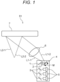
- a display device of a first embodiment (Example 1 of the display device) according to the present technology will be described with reference to Figs. 1 and 2 .
- Fig. 1 is a diagram illustrating a configuration example of the display device of the first embodiment according to the present technology, and specifically, is a diagram illustrating a display device 51.
- the display device 51 includes at least a light source 5, a first hologram (dispersion compensation hologram (dispersion compensation HOE)) 1, and a second hologram (combiner hologram (combiner HOE)) 7.
- the first hologram (dispersion compensation hologram (dispersion compensation HOE)) 1 compensates for dispersion of light emitted from the light source 5 and reflected by a dichroic mirror 3, and diffracts and emits the light as first diffracted light beams L1-1 and L1-2 via a first collimator lens 2 and a MEMS mirror 4 (moving in the direction of arrow M).
- the MEMS mirror 4 also referred to as a scanning mirror
- the first collimator lens 6 collimates the first diffracted light beams L1-1 and L1-2.
- the second hologram (combiner hologram (combiner (HOE)) 7 diffracts the light diffracted with compensated dispersion (first diffracted light beams L1-1 and L1-2) and emits the diffracted light as second diffracted light beams L2-1 and L2-2 in the direction of the user's eye.
- Fig. 2 is a diagram for describing diffraction efficiency in a plane of the first hologram (dispersion compensation hologram) 1 included in the display device (display device 51) of the first embodiment according to the present technology.
- Fig. 2A is a diagram illustrating a configuration example of a distribution of diffraction efficiency in a plane of the dispersion compensation hologram 1, in which a vertical axis (vertical direction in Fig. 2A ) is an adjustment axis of a maximum diffraction efficiency wavelength, and a horizontal axis (horizontal direction in Fig. 2A ) is an adjustment axis of a maximum diffraction efficiency value.
- Fig. 2B is an explanatory diagram for adjusting the diffraction efficiency, in which a vertical axis (vertical direction in Fig. 2B ) indicates the diffraction efficiency and a horizontal axis (horizontal direction in Fig. 2B ) indicates the wavelength.
- Area 1 (high level of diffraction efficiency) illustrated in Fig. 2B corresponds to area 1-A, area 1-B, and area 1-C illustrated in Fig. 2A
- area 2 (medium level of diffraction efficiency) corresponds to area 2-A, area 2-B, and area 2-C illustrated in Fig. 2A
- area 3 low level of diffraction efficiency
- Fig. 2C is an explanatory diagram for adjusting the wavelength of the maximum diffraction efficiency, in which a vertical axis (vertical direction in Fig. 2C ) indicates the diffraction efficiency and a horizontal axis (horizontal direction in Fig. 2C ) indicates the wavelength.
- Area A (short wavelength level) illustrated in Fig. 2C corresponds to area 1-A, area 2-A, and area 3-A illustrated in Fig. 2A
- area B (medium wavelength level) corresponds to area 1-B, area 2-B, and area 3-B illustrated in Fig. 2A
- area C long wavelength level
- the diffraction efficiency is adjusted by changing the position to which light is applied (incident) depending on the luminance and/or the wavelength of light emitted from the light source 5.
- the content described for the display device of the first embodiment (Example 1 of the display device) according to the present technology can be applied to the display devices of the second to fifth embodiments according to the present technology to be described later as long as there is no particular technical inconsistency.
- a display device of a second embodiment (Example 2 of the display device) according to the present technology will be described with reference to Fig. 3 .
- Fig. 3 is a diagram illustrating a configuration example of the display device of the second embodiment according to the present technology, and specifically, is a diagram illustrating a display device 53.
- the display device 53 includes a right-eye display device 53R and a left-eye display device 53L.
- the display device 53R for the right eye includes at least a light source 5R, a first hologram (dispersion compensation hologram (dispersion compensation HOE)) 1R, and a second hologram (combiner hologram (combiner HOE)) 7R.
- the first hologram (dispersion compensation hologram (dispersion compensation (HOE)) 1R compensates for dispersion of light emitted from the light source 5R and reflected by a dichroic mirror 3R, and diffracts and emits the light as first diffracted light beams L1-1R and L1-2R via the first collimator lens 2R and the MEMS mirror 4R.
- the MEMS mirror 4R also referred to as a scanning mirror
- the first collimator lens 6R collimates the first diffracted light beams L1-1R and L1-2R.
- the second hologram (combiner hologram (combiner (HOE)) 7R diffracts the light diffracted with compensated dispersion (first diffracted light beams L1-1R and L1-2R) and emits the diffracted light as second diffracted light beams L2-1R and L2-2R in the direction of the user's eye.
- the display device 53L for the left eye includes at least a light source 5L, a first hologram (dispersion compensation hologram (dispersion compensation HOE)) 1L, and a second hologram (combiner hologram (combiner HOE)) 7L.
- the first hologram (dispersion compensation hologram (dispersion compensation (HOE)) 1L compensates for dispersion of light emitted from the light source 5L and reflected by a dichroic mirror 3L, and diffracts and emits the light as first diffracted light beams L1-1L and L1-2L via the first collimator lens 2L and the MEMS mirror 4L.
- the MEMS mirror 4L also referred to as a scanning mirror
- the first collimator lens 6L collimates the first diffracted light beams L1-1L and L1-2L.
- the second hologram (combiner hologram (combiner (HOE)) 7L diffracts the light diffracted with compensated dispersion (first diffracted light beams L1-1L and L1-2L) and emits the diffracted light as second diffracted light beams L2-1L and L2-2L in the direction of the user's eye.
- the display device 53 it is possible to adjust output light of the second holograms (combiner holograms (combiners (HOE)) 7R and 7L at positions in planes of the first holograms (dispersion compensation holograms (dispersion compensation (HOE)) 1R and 1L to match luminance ratios of both eyes.
- Example 2 of the display device The contents described above for the display device of the second embodiment (Example 2 of the display device) according to the present technology can be applied to the display device of the first embodiment according to the present technology described above and the display devices of the third to fifth embodiments according to the present technology described later, unless there is a particular technical contradiction.
- a display device of a third embodiment (Example 3 of the display device) according to the present technology will be described with reference to Fig. 4 .
- Fig. 4 is a diagram illustrating a configuration example of the display device of the third embodiment according to the present technology, and specifically, is a diagram illustrating a display device 54.
- the display device 54 includes at least the light source 5, the first hologram (dispersion compensation hologram) 1, the second hologram (combiner hologram) 7, a light guide plate 8, and a prism 9.
- the first hologram (dispersion compensation hologram (dispersion compensation HOE)) 1 compensates for dispersion of light emitted from the light source 5 and reflected by the dichroic mirror 3, and diffracts and emits the light as the first diffracted light beams L1-1 and L1-2 via the first collimator lens 2 and the MEMS mirror 4 (moving in the direction of arrow M).
- the MEMS mirror 4 also referred to as a scanning mirror
- the first collimator lens 6 collimates the first diffracted light beams L1-1 and L1-2.
- the first diffracted light beams L1-1 and L1-2 are introduced into the light guide plate 8 via the prism 9, propagate in the light guide plate 8 by total reflection (the first diffracted light beam L1-1 is reflected in the region Q1 and the first diffracted light beam L1-2 is reflected in the region Q2), are emitted to the outside of the light guide plate 8, and are incident on the second hologram (combiner hologram) 7.
- the second hologram (combiner hologram (combiner (HOE)) 7 diffracts the light diffracted with compensated dispersion (first diffracted light beams L1-1 and L1-2) and emits the diffracted light as the second diffracted light beams L2-1 and L2-2 in the direction of the user's eye.
- Example 3 of the display device The contents described above for the display device of the third embodiment (Example 3 of the display device) according to the present technology can be applied to the display devices of the first and second embodiments according to the present technology described above and the display devices of the fourth and fifth embodiments according to the present technology described later, unless there is a particular technical contradiction.
- FIG. 5 is a diagram for describing diffraction efficiency in a plane of a first hologram (dispersion compensation hologram) 15 included in the display device of the fourth embodiment according to the present technology.
- Fig. 5A is a diagram illustrating a configuration example of a distribution of diffraction efficiency in a plane of a dispersion compensation hologram 15A
- Fig. 5B is a diagram illustrating a configuration example of a distribution of diffraction efficiency in a plane of a dispersion compensation hologram 15B
- Fig. 5C is a diagram illustrating a configuration example of a distribution of diffraction efficiency in a plane of a dispersion compensation hologram 15C
- Fig. 5D is a diagram illustrating a configuration example of a distribution of diffraction efficiency in a plane of a dispersion compensation hologram 15D.
- a vertical axis direction (vertical direction in Fig. 5A ) on the left side in the plane of the dispersion compensation hologram 15A is a 1-A region (the above-described area 1 (high intensity) + area A (short wavelength)) and a 3-A region (the above-described area 3 (low intensity) + area A (short wavelength)), and the vertical axis direction (vertical direction in Fig. 5A ) on the right side in the plane of the dispersion compensation hologram 15A is a 2-A region (the above-described area 1 (medium intensity) + area A (short wavelength)) and a 4-A region (area 4 (minimum intensity) + area A (short wave length)).
- a horizontal axis direction (horizontal direction in Fig. 5A ) on the upper side in the plane of the dispersion compensation hologram 15A is the 1-A region (the above-described area 1 (high intensity) + area A (short wavelength)) and the 2-A region (the above-described area 2 (medium intensity) + area A (short wavelength)), and the horizontal axis direction (horizontal direction in Fig. 5A ) on the lower side in the plane of the dispersion compensation hologram 15A is a 3-A region (the above-described area 3 (low intensity) + area A (short wavelength)) and the 4-A region (area 4 (minimum intensity) + area A (short wave length)).
- the vertical axis direction (vertical direction in Fig. 5B ) on the left side in the plane of the dispersion compensation hologram 15B is the 1-A region (the above-described area 1 (high intensity) + area A (short wavelength)) and a 1-C region (the above-described area 1 (high intensity) + area C (long wavelength)), and the vertical axis direction (vertical direction in Fig. 5B ) on the right side in the plane of the dispersion compensation hologram 15B is a 1-B region (the above-described area 1 (medium intensity) + area B (medium wavelength) and a 1-D region (area 1 (high intensity) + area D (longest wavelength)).
- the horizontal axis direction (horizontal direction in Fig. 5B ) on the upper side in the plane of the dispersion compensation hologram 15B is the 1-A region (the above-described area 1 (high intensity) + area A (short wavelength)) and the 1-B region (the above-described area 1 (high intensity) + area B (medium wavelength)), and the horizontal axis direction (horizontal direction in Fig. 5B ) on the lower side in the plane of the dispersion compensation hologram 15B is the 1-C region (the above-described area 1 (high intensity) + area C (long wavelength)) and the 1-D region (area 1 (high intensity) + area D (long wavelength)).
- a region in which the maximum intensity of the diffraction efficiency changes and a region in which the wavelength at which the diffraction efficiency becomes the maximum intensity changes are randomly formed.
- the vertical axis direction (vertical direction in Fig. 5C ) on the left side in the plane of the dispersion compensation hologram 15C is a 2-B region (the above-described area 2 (medium intensity) + area B (medium wavelength)), the 1-B region (the above-described area 1 (high intensity) + area B (medium wavelength)), and the 1-C region (the above-described area 1 (high intensity) + area C (long wavelength)), the vertical axis direction (vertical direction in Fig.
- the 5C in the middle in the plane of the dispersion compensation hologram 15B is a 3-C region (the above-described area 3 (low intensity) + area C (long wavelength)), the 1-A region (the above-described area 1 (high intensity) + area A (short wavelength)), and a 3-B region (the above-described area 3 (low intensity) + area B (medium wavelength)), and the vertical axis direction (vertical direction in Fig.
- the 3-A region (the above-described area 3 (low intensity) + area A (short wavelength)
- a 2-C region (the above-described area 2 (medium intensity) + area C (long wavelength)
- the 2-A region (the above-described area 1 (medium intensity) + area A (short wavelength)).
- the horizontal axis direction (the horizontal direction in Fig. 5C ) on the upper side in the plane of the dispersion compensation hologram 15C is the 2-B region (the above-described area 2 (medium intensity) + area B (medium wavelength)), the 3-C region (the above-described area 3 (low intensity) + area C (long wavelength)), and the 3-A region (the above-described area 3 (low intensity) + area A (short wavelength)), the horizontal axis direction (horizontal direction in Fig.
- the dispersion compensation hologram 15C at the center in the plane of the dispersion compensation hologram 15C is the 1-B region (the above-described area 1 (high intensity) + area B (medium wavelength)), the 1-A region (the above-described area 1 (high intensity) + area A (short wavelength)), and the 2-C region (the above-described area 2 (medium intensity) + area C (long wavelength)), and the horizontal axis direction (horizontal direction in Fig.
- the dispersion compensation hologram 15C on the lower side in the plane of the dispersion compensation hologram 15C is the 1-C region (the above-described area 1 (high intensity) + area C (long wavelength)), the 3-B region (the above-described area 3 (low intensity) + area B (medium wavelength)), and the 2-A region (the above-described area 1 (medium intensity) + area A (short wavelength)) .
- a region in which the maximum intensity of the diffraction efficiency continuously changes is formed in an area on the vertical axis (in the vertical direction of Fig. 15D, the intensity distribution is continuous), and a region in which the wavelength at which the diffraction efficiency becomes the maximum intensity continuously changes is formed in an area on the horizontal axis (the wavelength distribution is continuous in the left-right direction in Fig. 15D).
- a region in which the maximum intensity of the diffraction efficiency discontinuously changes may be formed, and a region in which the wavelength at which the diffraction efficiency becomes the maximum intensity discontinuously changes may be formed.
- a display device of a fifth embodiment (Example 5 of the display device) according to the present technology will be described with reference to Fig. 6 .
- Fig. 6 is a diagram illustrating a configuration example of a display device of a fifth embodiment according to the present technology. Specifically, it is a diagram illustrating a display device 56.
- Fig. 6A is a diagram illustrating the display device 56
- Fig. 6B is an enlarged diagram of a region P6A illustrated in Fig. 6A
- Fig. 6C is an enlarged diagram of the region P6A illustrated in Fig. 6A
- a detection mechanism 60C is an enlarged diagram of the region P6A illustrated in Fig. 6A
- a detection mechanism 60D is an enlarged diagram of the region P6A illustrated in Fig. 6A , and is a diagram illustrating a detection mechanism 60D.
- the display device 56 includes at least the light source 5, the first hologram (dispersion compensation hologram) 1, and the second hologram (combiner hologram) 7.
- the first hologram (dispersion compensation hologram (dispersion compensation HOE)) 1 compensates for dispersion of light emitted from the light source 5 and reflected by the dichroic mirror 3, and diffracts and emits the light as the first diffracted light beams L1-1 and L1-2 via the first collimator lens 2 and the MEMS mirror 4 (moving in the direction of arrow M).
- the MEMS mirror 4 also referred to as a scanning mirror
- the first collimator lens 6 collimates the first diffracted light beams L1-1 and L1-2.
- the second hologram (combiner hologram (combiner (HOE)) 7 diffracts the light diffracted with compensated dispersion (first diffracted light beams L1-1 and L1-2) and emits the diffracted light as the second diffracted light beams L2-1 and L2-2 in the direction of the user's eye.
- the light (for example, red light) emitted from the light source 5R passes through the dichroic mirror 3R and enters a light intensity detector 10B-1
- light (for example, green light) emitted from a light source 5G passes through a dichroic mirror 3G and enters a light intensity detector 10B-2
- light (for example, blue light) emitted from a light source 5B passes through a dichroic mirror 3B and enters a light intensity detector 10B-3
- intensity fluctuations of the light (for example, red light) emitted from the light source 5R, the light (for example, green light) emitted from the light source 5G, and the light (for example, blue light) emitted from the light source 5B can be detected.
- the detection of this intensity variation makes it possible to actively move and adjust the dispersion compensation.
- the light (for example, red light) emitted from the light source 5R is reflected by the dichroic mirror 3R and incident on the first hologram (dispersion compensation hologram) 1, and incident on a light spectral sensitivity detector 10C
- the light (for example, green light) emitted from the light source 5G is reflected by the dichroic mirror 3G and incident on the first hologram (dispersion compensation hologram) 1, and incident on the light spectral sensitivity detector 10C
- the light (for example, blue light) emitted from the light source 5B is reflected by the dichroic mirror 3B and incident on the first hologram (dispersion compensation hologram) 1, and incident on the light spectral sensitivity detector 10C, so that it is possible to detect a variation in light spectral sensitivity (light spectral intensity).
- the dispersion compensation can be actively moved and adjusted.
- a temperature detector 10D-1 is connected to the light source 5R
- a temperature detector 10D-2 is connected to the light source 5G
- a temperature detector 10D-3 is connected to the light source 5B, and temperature fluctuations of the light source 5R, the light source 5G, and the light source 5B can be detected.
- the detection of this temperature variation makes it possible to actively move and adjust the dispersion compensation.
- the present technology can also have the following configurations.
Applications Claiming Priority (2)
| Application Number | Priority Date | Filing Date | Title |
|---|---|---|---|
| JP2021045853 | 2021-03-19 | ||
| PCT/JP2022/005603 WO2022196204A1 (ja) | 2021-03-19 | 2022-02-14 | 表示装置 |
Publications (1)
| Publication Number | Publication Date |
|---|---|
| EP4310580A1 true EP4310580A1 (de) | 2024-01-24 |
Family
ID=83322221
Family Applications (1)
| Application Number | Title | Priority Date | Filing Date |
|---|---|---|---|
| EP22770963.1A Pending EP4310580A1 (de) | 2021-03-19 | 2022-02-14 | Anzeigevorrichtung |
Country Status (3)
| Country | Link |
|---|---|
| EP (1) | EP4310580A1 (de) |
| CN (1) | CN117043662A (de) |
| WO (1) | WO2022196204A1 (de) |
Family Cites Families (10)
| Publication number | Priority date | Publication date | Assignee | Title |
|---|---|---|---|---|
| JP2585717B2 (ja) | 1988-06-03 | 1997-02-26 | キヤノン株式会社 | 表示装置 |
| JPH06202037A (ja) | 1992-12-28 | 1994-07-22 | Canon Inc | ホログラフィックディスプレイ |
| JP3623250B2 (ja) * | 1993-06-23 | 2005-02-23 | オリンパス株式会社 | 映像表示装置 |
| JP2001519928A (ja) * | 1998-01-28 | 2001-10-23 | コーニンクレッカ フィリップス エレクトロニクス エヌ ヴィ | ヘッド搭載型ディスプレイ |
| WO2017047528A1 (ja) * | 2015-09-16 | 2017-03-23 | コニカミノルタ株式会社 | 画像表示装置およびヘッドマウントディスプレイ |
| JP2020514783A (ja) * | 2017-01-26 | 2020-05-21 | ディジレンズ インコーポレイテッド | 均一出力照明を有する導波管 |
| CN114185179A (zh) * | 2017-11-06 | 2022-03-15 | 奇跃公司 | 利用阴影掩模实现可调梯度图案化的方法和系统 |
| WO2019125575A1 (en) * | 2017-12-19 | 2019-06-27 | Akonia Holographics Llc | Optical system with dispersion compensation |
| WO2019185510A1 (de) * | 2018-03-26 | 2019-10-03 | Seereal Technologies S.A. | Anzeigevorrichtung |
| JP2020042212A (ja) * | 2018-09-12 | 2020-03-19 | ソニー株式会社 | 表示装置、表示制御方法及び記録媒体 |
-
2022
- 2022-02-14 EP EP22770963.1A patent/EP4310580A1/de active Pending
- 2022-02-14 WO PCT/JP2022/005603 patent/WO2022196204A1/ja active Application Filing
- 2022-02-14 CN CN202280020791.7A patent/CN117043662A/zh active Pending
Also Published As
| Publication number | Publication date |
|---|---|
| WO2022196204A1 (ja) | 2022-09-22 |
| CN117043662A (zh) | 2023-11-10 |
Similar Documents
| Publication | Publication Date | Title |
|---|---|---|
| JP7446620B2 (ja) | オーバーラップするプロジェクター組立体を有するニアアイディスプレイ | |
| US10048500B2 (en) | Directionally illuminated waveguide arrangement | |
| US11202043B1 (en) | Self-testing display device | |
| JP7185331B2 (ja) | インテグラルイメージング方式のライトフィールドディスプレイ用にライトフィールド画像をレンダリングする方法 | |
| KR102139268B1 (ko) | 눈 투영 시스템 | |
| JP3984907B2 (ja) | 画像観察システム | |
| US9851562B2 (en) | Embedded grating structure | |
| JP5237268B2 (ja) | 表示装置 | |
| JP2019204092A (ja) | 仮想および拡張現実のためのアドレス可能焦点を伴う自由形状光学システムを用いて立体視を表示する方法およびシステム | |
| US20170255012A1 (en) | Head mounted display using spatial light modulator to move the viewing zone | |
| JP6424552B2 (ja) | 画像表示装置 | |
| JP7185303B2 (ja) | インテグラルイメージングおよびリレー光学部品を用いたヘッドマウント・ライトフィールド・ディスプレイ | |
| JP7182796B2 (ja) | インテグラルイメージングおよび導波路プリズムを用いたヘッドマウント・ライトフィールド・ディスプレイ | |
| CN107209390A (zh) | 组合高分辨率窄场显示和中分辨率宽场显示 | |
| JP2020526793A (ja) | 視野を拡大するためのディスプレイデバイス | |
| JP2005070255A (ja) | 虚像表示装置 | |
| GB2268283A (en) | Stereoscopic optical system | |
| EP4310580A1 (de) | Anzeigevorrichtung | |
| US20170010467A1 (en) | Hmpd with near eye projection | |
| US20220163816A1 (en) | Display apparatus for rendering three-dimensional image and method therefor | |
| JP7127415B2 (ja) | 虚像表示装置 | |
| JP3396074B2 (ja) | 映像表示装置 | |
| US20230418034A1 (en) | Anamorphic directional illumination device | |
| JP3469854B2 (ja) | 三次元表示装置 | |
| US11863912B2 (en) | Lighting unit and display with wavelength-selective illumination |
Legal Events
| Date | Code | Title | Description |
|---|---|---|---|
| STAA | Information on the status of an ep patent application or granted ep patent |
Free format text: STATUS: THE INTERNATIONAL PUBLICATION HAS BEEN MADE |
|
| PUAI | Public reference made under article 153(3) epc to a published international application that has entered the european phase |
Free format text: ORIGINAL CODE: 0009012 |
|
| STAA | Information on the status of an ep patent application or granted ep patent |
Free format text: STATUS: REQUEST FOR EXAMINATION WAS MADE |
|
| 17P | Request for examination filed |
Effective date: 20231003 |
|
| AK | Designated contracting states |
Kind code of ref document: A1 Designated state(s): AL AT BE BG CH CY CZ DE DK EE ES FI FR GB GR HR HU IE IS IT LI LT LU LV MC MK MT NL NO PL PT RO RS SE SI SK SM TR |