EP4310550A1 - Informationsverarbeitungsvorrichtung, steuerungsverfahren, programm und speichermedium - Google Patents
Informationsverarbeitungsvorrichtung, steuerungsverfahren, programm und speichermedium Download PDFInfo
- Publication number
- EP4310550A1 EP4310550A1 EP21931426.7A EP21931426A EP4310550A1 EP 4310550 A1 EP4310550 A1 EP 4310550A1 EP 21931426 A EP21931426 A EP 21931426A EP 4310550 A1 EP4310550 A1 EP 4310550A1
- Authority
- EP
- European Patent Office
- Prior art keywords
- water
- ship
- data
- point cloud
- wave
- Prior art date
- Legal status (The legal status is an assumption and is not a legal conclusion. Google has not performed a legal analysis and makes no representation as to the accuracy of the status listed.)
- Pending
Links
- 230000010365 information processing Effects 0.000 title claims abstract description 37
- 238000000034 method Methods 0.000 title claims description 69
- 238000004364 calculation method Methods 0.000 claims abstract description 46
- XLYOFNOQVPJJNP-UHFFFAOYSA-N water Substances O XLYOFNOQVPJJNP-UHFFFAOYSA-N 0.000 claims abstract description 44
- 238000005259 measurement Methods 0.000 claims abstract description 41
- 238000013075 data extraction Methods 0.000 claims abstract description 6
- 238000001514 detection method Methods 0.000 claims description 93
- 238000012545 processing Methods 0.000 claims description 25
- 239000000284 extract Substances 0.000 abstract description 13
- 230000008569 process Effects 0.000 description 46
- 238000010586 diagram Methods 0.000 description 20
- 238000000605 extraction Methods 0.000 description 12
- 230000015654 memory Effects 0.000 description 11
- 238000004088 simulation Methods 0.000 description 11
- 230000004048 modification Effects 0.000 description 8
- 238000012986 modification Methods 0.000 description 8
- 239000011159 matrix material Substances 0.000 description 6
- 238000009826 distribution Methods 0.000 description 5
- 230000006870 function Effects 0.000 description 5
- 230000005484 gravity Effects 0.000 description 5
- 238000011156 evaluation Methods 0.000 description 4
- 238000000513 principal component analysis Methods 0.000 description 4
- 230000009466 transformation Effects 0.000 description 4
- 238000001914 filtration Methods 0.000 description 3
- 238000012935 Averaging Methods 0.000 description 2
- FFBHFFJDDLITSX-UHFFFAOYSA-N benzyl N-[2-hydroxy-4-(3-oxomorpholin-4-yl)phenyl]carbamate Chemical compound OC1=C(NC(=O)OCC2=CC=CC=C2)C=CC(=C1)N1CCOCC1=O FFBHFFJDDLITSX-UHFFFAOYSA-N 0.000 description 2
- 230000008859 change Effects 0.000 description 2
- 238000006243 chemical reaction Methods 0.000 description 2
- 230000002093 peripheral effect Effects 0.000 description 2
- 230000001141 propulsive effect Effects 0.000 description 2
- 238000005070 sampling Methods 0.000 description 2
- 101100228469 Caenorhabditis elegans exp-1 gene Proteins 0.000 description 1
- 230000001133 acceleration Effects 0.000 description 1
- 230000003044 adaptive effect Effects 0.000 description 1
- 238000004422 calculation algorithm Methods 0.000 description 1
- 238000004891 communication Methods 0.000 description 1
- 230000003247 decreasing effect Effects 0.000 description 1
- 230000000694 effects Effects 0.000 description 1
- 230000001678 irradiating effect Effects 0.000 description 1
- 230000007246 mechanism Effects 0.000 description 1
- 239000000203 mixture Substances 0.000 description 1
- 230000004044 response Effects 0.000 description 1
- 230000008685 targeting Effects 0.000 description 1
- 238000012546 transfer Methods 0.000 description 1
Images


Classifications
-
- G—PHYSICS
- G01—MEASURING; TESTING
- G01S—RADIO DIRECTION-FINDING; RADIO NAVIGATION; DETERMINING DISTANCE OR VELOCITY BY USE OF RADIO WAVES; LOCATING OR PRESENCE-DETECTING BY USE OF THE REFLECTION OR RERADIATION OF RADIO WAVES; ANALOGOUS ARRANGEMENTS USING OTHER WAVES
- G01S7/00—Details of systems according to groups G01S13/00, G01S15/00, G01S17/00
- G01S7/48—Details of systems according to groups G01S13/00, G01S15/00, G01S17/00 of systems according to group G01S17/00
- G01S7/4808—Evaluating distance, position or velocity data
-
- G—PHYSICS
- G01—MEASURING; TESTING
- G01S—RADIO DIRECTION-FINDING; RADIO NAVIGATION; DETERMINING DISTANCE OR VELOCITY BY USE OF RADIO WAVES; LOCATING OR PRESENCE-DETECTING BY USE OF THE REFLECTION OR RERADIATION OF RADIO WAVES; ANALOGOUS ARRANGEMENTS USING OTHER WAVES
- G01S17/00—Systems using the reflection or reradiation of electromagnetic waves other than radio waves, e.g. lidar systems
- G01S17/86—Combinations of lidar systems with systems other than lidar, radar or sonar, e.g. with direction finders
-
- G—PHYSICS
- G01—MEASURING; TESTING
- G01S—RADIO DIRECTION-FINDING; RADIO NAVIGATION; DETERMINING DISTANCE OR VELOCITY BY USE OF RADIO WAVES; LOCATING OR PRESENCE-DETECTING BY USE OF THE REFLECTION OR RERADIATION OF RADIO WAVES; ANALOGOUS ARRANGEMENTS USING OTHER WAVES
- G01S17/00—Systems using the reflection or reradiation of electromagnetic waves other than radio waves, e.g. lidar systems
- G01S17/02—Systems using the reflection of electromagnetic waves other than radio waves
- G01S17/04—Systems determining the presence of a target
-
- G—PHYSICS
- G01—MEASURING; TESTING
- G01S—RADIO DIRECTION-FINDING; RADIO NAVIGATION; DETERMINING DISTANCE OR VELOCITY BY USE OF RADIO WAVES; LOCATING OR PRESENCE-DETECTING BY USE OF THE REFLECTION OR RERADIATION OF RADIO WAVES; ANALOGOUS ARRANGEMENTS USING OTHER WAVES
- G01S17/00—Systems using the reflection or reradiation of electromagnetic waves other than radio waves, e.g. lidar systems
- G01S17/02—Systems using the reflection of electromagnetic waves other than radio waves
- G01S17/06—Systems determining position data of a target
- G01S17/08—Systems determining position data of a target for measuring distance only
-
- G—PHYSICS
- G01—MEASURING; TESTING
- G01S—RADIO DIRECTION-FINDING; RADIO NAVIGATION; DETERMINING DISTANCE OR VELOCITY BY USE OF RADIO WAVES; LOCATING OR PRESENCE-DETECTING BY USE OF THE REFLECTION OR RERADIATION OF RADIO WAVES; ANALOGOUS ARRANGEMENTS USING OTHER WAVES
- G01S17/00—Systems using the reflection or reradiation of electromagnetic waves other than radio waves, e.g. lidar systems
- G01S17/88—Lidar systems specially adapted for specific applications
- G01S17/89—Lidar systems specially adapted for specific applications for mapping or imaging
-
- G—PHYSICS
- G01—MEASURING; TESTING
- G01S—RADIO DIRECTION-FINDING; RADIO NAVIGATION; DETERMINING DISTANCE OR VELOCITY BY USE OF RADIO WAVES; LOCATING OR PRESENCE-DETECTING BY USE OF THE REFLECTION OR RERADIATION OF RADIO WAVES; ANALOGOUS ARRANGEMENTS USING OTHER WAVES
- G01S17/00—Systems using the reflection or reradiation of electromagnetic waves other than radio waves, e.g. lidar systems
- G01S17/88—Lidar systems specially adapted for specific applications
- G01S17/93—Lidar systems specially adapted for specific applications for anti-collision purposes
-
- G—PHYSICS
- G01—MEASURING; TESTING
- G01S—RADIO DIRECTION-FINDING; RADIO NAVIGATION; DETERMINING DISTANCE OR VELOCITY BY USE OF RADIO WAVES; LOCATING OR PRESENCE-DETECTING BY USE OF THE REFLECTION OR RERADIATION OF RADIO WAVES; ANALOGOUS ARRANGEMENTS USING OTHER WAVES
- G01S17/00—Systems using the reflection or reradiation of electromagnetic waves other than radio waves, e.g. lidar systems
- G01S17/88—Lidar systems specially adapted for specific applications
- G01S17/95—Lidar systems specially adapted for specific applications for meteorological use
-
- G—PHYSICS
- G01—MEASURING; TESTING
- G01S—RADIO DIRECTION-FINDING; RADIO NAVIGATION; DETERMINING DISTANCE OR VELOCITY BY USE OF RADIO WAVES; LOCATING OR PRESENCE-DETECTING BY USE OF THE REFLECTION OR RERADIATION OF RADIO WAVES; ANALOGOUS ARRANGEMENTS USING OTHER WAVES
- G01S7/00—Details of systems according to groups G01S13/00, G01S15/00, G01S17/00
- G01S7/48—Details of systems according to groups G01S13/00, G01S15/00, G01S17/00 of systems according to group G01S17/00
- G01S7/4802—Details of systems according to groups G01S13/00, G01S15/00, G01S17/00 of systems according to group G01S17/00 using analysis of echo signal for target characterisation; Target signature; Target cross-section
-
- G—PHYSICS
- G01—MEASURING; TESTING
- G01S—RADIO DIRECTION-FINDING; RADIO NAVIGATION; DETERMINING DISTANCE OR VELOCITY BY USE OF RADIO WAVES; LOCATING OR PRESENCE-DETECTING BY USE OF THE REFLECTION OR RERADIATION OF RADIO WAVES; ANALOGOUS ARRANGEMENTS USING OTHER WAVES
- G01S7/00—Details of systems according to groups G01S13/00, G01S15/00, G01S17/00
- G01S7/48—Details of systems according to groups G01S13/00, G01S15/00, G01S17/00 of systems according to group G01S17/00
- G01S7/497—Means for monitoring or calibrating
-
- Y—GENERAL TAGGING OF NEW TECHNOLOGICAL DEVELOPMENTS; GENERAL TAGGING OF CROSS-SECTIONAL TECHNOLOGIES SPANNING OVER SEVERAL SECTIONS OF THE IPC; TECHNICAL SUBJECTS COVERED BY FORMER USPC CROSS-REFERENCE ART COLLECTIONS [XRACs] AND DIGESTS
- Y02—TECHNOLOGIES OR APPLICATIONS FOR MITIGATION OR ADAPTATION AGAINST CLIMATE CHANGE
- Y02A—TECHNOLOGIES FOR ADAPTATION TO CLIMATE CHANGE
- Y02A90/00—Technologies having an indirect contribution to adaptation to climate change
- Y02A90/30—Assessment of water resources
Definitions
- the present disclosure relates to processing of data measured in a ship.
- Patent Document 1 discloses an autonomous movement system, which determines whether or not an object detected in the voxel obtained by dividing the space with a predetermined rule is a stationary object or a movable object, and performs matching of the map information and the measurement data for the voxel in which the stationary object is present.
- Patent Document 2 discloses a scan matching method for performing self-position estimation by collation between the voxel data including an average vector and a covariance matrix of a stationary object for each voxel and the point cloud data outputted by the lidar.
- Patent Document 3 discloses a technique for changing an attitude of a ship, in an automatic berthing device for performing automatic berthing of the ship, so that the light irradiated from the lidar can be reflected by the object around the berthing position and received by the lidar.
- the present disclosure has been made to solve the problems as described above, and a main object thereof is to provide an information processing device capable of estimating the height of the water surface with high accuracy.
- the invention described in claim is an information processing device including: a point cloud data acquisition means configured to acquire point cloud data generated by a measurement device provided on a ship; a water-surface reflection data extraction means configured to extract data obtained by measuring a position which is a predetermined distance away from a shore and which is within a predetermined distance from a measurement position of the measurement device, as a water-surface reflection data measured by reflection at a water surface; and a water-surface height calculation means configured to calculate a water-surface height based on the water-surface reflection data.
- the invention described in claim is a control method executed by a computer, comprising: acquiring point cloud data generated by a measurement device provided on a ship; extracting data obtained by measuring a position which is a predetermined distance away from a shore and which is within a predetermined distance from a measurement position of the measurement device, as a water-surface reflection data measured by reflection at a water surface; and calculating a water-surface height based on the water-surface reflection data.
- the invention described in claim is a program causing a computer to execute processing of: acquiring point cloud data generated by a measurement device provided on a ship; extracting data obtained by measuring a position which is a predetermined distance away from a shore and which is within a predetermined distance from a measurement position of the measurement device, as a water-surface reflection data measured by reflection at a water surface; and calculating a water-surface height based on the water-surface reflection data.
- an information processing device comprising: a point cloud data acquisition means configured to acquire point cloud data generated by a measurement device provided on a ship; a water-surface reflection data extraction means configured to extract data obtained by measuring a position which is a predetermined distance away from a shore and which is within a predetermined distance from a measurement position of the measurement device, as a water-surface reflection data measured by reflection at a water surface; and a water-surface height calculation means configured to calculate a water-surface height based on the water-surface reflection data.
- the point cloud data acquisition means acquires point cloud data generated by a measurement device provided on a ship.
- the water-surface reflection data extraction means extracts data obtained by measuring a position which is a predetermined distance away from a shore and which is within a predetermined distance from a measurement position of the measurement device, as a water-surface reflection data measured by reflection at a water surface.
- the water-surface height calculation means calculates a water-surface height based on the water-surface reflection data.
- the water-surface height can be calculated with high accuracy using the water-surface reflection data.
- the water-surface height calculation means calculates an average of the values of the water-surface reflection data in a height direction as the water-surface height. In another mode, the water-surface height calculation means calculates an average and a variance of the values in the height direction of the water-surface reflection data, and calculates the average as the water-surface height when the variance is smaller than a predetermined value.
- Still another mode of the above information processing device further includes a detection means configured to set a search range based on the measurement position and the water-surface height, and detect an obstacle and a ship-wave based on the point cloud data belonging to the search range.
- the water-surface height can be used to detect obstacles and ship-waves.
- the detection means determines whether or not the point cloud data belonging to the search range forms a linear shape, and detects a linear point cloud data as a ship-wave when the linear point cloud data exists for a predetermined time. Also, the detection means determines whether or not the point cloud data belonging to the search range forms a cluster, and detects a point cloud data forming the cluster as an obstacle when the point cloud data forming the cluster exists for a predetermined time.
- the detection means changes a height range of the search range based on a variance of a value in a height direction of the water-surface reflection data.
- an appropriate search range can be set according to the height of the wave.
- a control method executed by a computer including: acquiring point cloud data generated by a measurement device provided on a ship; extracting data obtained by measuring a position which is a predetermined distance away from a shore and which is within a predetermined distance from a measurement position of the measurement device, as a water-surface reflection data measured by reflection at a water surface; and calculating a water-surface height based on the water-surface reflection data.
- the water-surface height can be calculated with high accuracy using the water-surface reflection data.
- a program causing a computer to execute processing of: acquiring point cloud data generated by a measurement device provided on a ship; extracting data obtained by measuring a position which is a predetermined distance away from a shore and which is within a predetermined distance from a measurement position of the measurement device, as a water-surface reflection data measured by reflection at a water surface; and calculating a water-surface height based on the water-surface reflection data.
- FIG. 1 is a schematic configuration of a driving assistance system according to the present embodiment.
- the driving assistance system includes an information processing device 1 that moves together with a ship serving as a mobile body, and a sensor group 2 mounted on the ship.
- a ship that moves together with the information processing device 1 is also referred to as a "target ship”.
- the information processing device 1 is electrically connected to the sensor group 2, and estimates the position (also referred to as a "self-position") of the target ship in which the information processing device 1 is provided, based on the outputs of various sensors included in the sensor group 2. Then, the information processing device 1 performs driving assistance such as autonomous driving control of the target ship on the basis of the estimation result of the self-position.
- the driving assistance includes berthing assistance such as automatic berthing.
- "berthing” includes not only the case of berthing the target ship to the wharf but also the case of berthing the target ship to a structural body such as a pier.
- the information processing device 1 may be a navigation device provided in the target ship or an electronic control device built in the ship.
- the information processing device 1 stores a map database (DB: DataBase 10) including voxel data "VD".
- the voxel data VD is the data which records the position data of the stationary structures in each voxel.
- the voxel represents a cube (regular lattice) which is the smallest unit of three-dimensional space.
- the voxel data VD includes the data representing the measured point cloud data of the stationary structures in the voxels by the normal distribution. As will be described later, the voxel data is used for scan matching using NDT (Normal Distributions Transform).
- the information processing device 1 performs, for example, estimation of a position on a plane, a height position, a yaw angle, a pitch angle, and a roll angle of the target ship by NDT scan matching.
- the self-position includes the attitude angle such as the yaw angle of the target ship.
- the sensor group 2 includes various external and internal sensors provided on the target ship.
- the sensor group 2 includes a Lidar (Light Detection and Ranging or Laser Illuminated Detection And Ranging) 3, a speed sensor 4 that detects the speed of the target ship, a GPS (Global Positioning Satellite) receiver 5, and an IMU (Inertial Measurement Unit) 6 that measures the acceleration and angular velocity of the target ship in three-axis directions.
- Lidar Light Detection and Ranging or Laser Illuminated Detection And Ranging
- GPS Global Positioning Satellite
- IMU Inertial Measurement Unit
- the Lidar 3 By emitting a pulse laser with respect to a predetermined angular range in the horizontal and vertical directions, the Lidar 3 discretely measures the distance to the object existing in the outside world and generates three-dimensional point cloud data indicating the position of the object.
- the Lidar 3 includes an irradiation unit for irradiating a laser beam while changing the irradiation direction, a light receiving unit for receiving the reflected light (scattered light) of the irradiated laser beam, and an output unit for outputting scan data (a point constituting the point cloud data.
- measurement point a point constituting the point cloud data.
- the measurement point is generated based on the irradiation direction corresponding to the laser beam received by the light receiving unit and the response delay time of the laser beam identified based on the received light signal described above.
- the Lidar 3 is an example of a "measurement device" in the present invention.
- the speed sensor 4 may be, for example, a Doppler based speed meter, or a GNSS based speed meter.
- the sensor group 2 may have a receiver that generates the positioning result of GNSS other than GPS, instead of the GPS receiver 5.
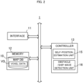
- FIG. 2 is a block diagram illustrating an example of a hardware configuration of the information processing device 1.
- the information processing device 1 mainly includes an interface 11, a memory 12, and a controller 13. Each of these elements is connected to each other through a bus line.
- the interface 11 performs the interface operation related to the transfer of data between the information processing device 1 and the external device.
- the interface 11 acquires the output data from the sensors of the sensor group 2 such as the Lidar 3, the speed sensor 4, the GPS receiver 5, and the IMU 6, and supplies the data to the controllers 13.
- the interface 11 also supplies, for example, the signals related to the control of the target ship generated by the controller 13 to each component of the target ship to control the operation of the target ship.
- the target ship includes a driving source such as an engine or an electric motor, a screw for generating a propulsive force in the traveling direction based on the driving force of the driving source, a thruster for generating a lateral propulsive force based on the driving force of the driving source, and a rudder which is a mechanism for freely setting the traveling direction of the ship.
- a driving source such as an engine or an electric motor
- a screw for generating a propulsive force in the traveling direction based on the driving force of the driving source
- a thruster for generating a lateral propulsive force based on the driving force of the driving source
- a rudder which is a mechanism for freely setting the traveling direction of the ship.
- the interface 11 supplies the control signal generated by the controller 13 to each of these components.
- the interface 11 supplies the control signals generated by the controller 13 to the electronic control device.
- the interface 11 may be a wireless interface such as a network adapter for performing wireless communication, or a hardware interface such as a cable for connecting to an external device. Also, the interface 11 may perform the interface operations with various peripheral devices such as an input device, a display device, a sound output device, and the like.
- the memory 12 may include various volatile and non-volatile memories such as a RAM (Random Access Memory), a ROM (Read Only Memory), a hard disk drive, a flash memory, and the like.
- the memory 12 stores a program for the controller 13 to perform a predetermined processing.
- the program executed by the controller 13 may be stored in a storage medium other than the memory 12.
- the memory 12 also stores a map DB 10 including the voxel data VD.
- the map DB 10 stores, for example, information about berthing locations (including shores, piers) and information about waterways in which ships can move, in addition to the voxel-data VD.
- the map DB 10 may be stored in a storage device external to the information processing device 1, such as a hard disk connected to the information processing device 1 through the interface 11.
- the above storage device may be a server device that communicates with the information processing device 1. Further, the above storage device may be configured by a plurality of devices.
- the map DB 10 may be updated periodically. In this case, for example, the controller 13 receives the partial map information about the area, to which the self-position belongs, from the server device that manages the map information via the interface 11, and reflects it in the map DB 10.
- the memory 12 stores information required for the processing performed by the information processing device 1 in the present embodiment.
- the memory 12 stores information used for setting the size of the down-sampling, which is performed on the point cloud data obtained when the Lidar 3 performs scanning for one period.
- the controller 13 includes one or more processors, such as a CPU (Central Processing Unit), a GPU (Graphics Processing Unit), and a TPU (Tensor Processing Unit, and controls the entire information processing device 1. In this case, the controller 13 performs processing related to the self-position estimation and the driving assistance by executing programs stored in the memory 12.
- processors such as a CPU (Central Processing Unit), a GPU (Graphics Processing Unit), and a TPU (Tensor Processing Unit, and controls the entire information processing device 1.
- the controller 13 performs processing related to the self-position estimation and the driving assistance by executing programs stored in the memory 12.
- controller 13 functionally includes a self-position estimation unit 15, and an obstacle/ship-wave detection unit 16.
- the controller 13 functions as "point cloud data acquisition means”, “water-surface reflection data extraction means”, “water surface height calculation means”, “detection means” and a computer for executing the program.
- the self-position estimation unit 15 estimates the self-position by performing scan matching (NDT scan matching) based on NDT on the basis of the point cloud data based on the output of the Lidar 3 and the voxel data VD corresponding to the voxel to which the point cloud data belongs.
- the point cloud data to be processed by the self-position estimation unit 15 may be the point cloud data generated by the Lidar 3 or may be the point cloud data obtained by after down-sampling the point cloud data.
- the obstacle/ship-wave detection unit 16 detects obstacles and ship-waves around the ship using the point cloud data outputted by the Lidar 3.
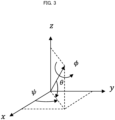
- FIG. 3 is a diagram in which a self-position to be estimated by the self-position estimation unit 15 is represented by three-dimensional orthogonal coordinates.
- the self-position in the plane defined on the three-dimensional orthogonal coordinates of xyz is represented by the coordinates "(x,y,z)", the roll angle " ⁇ ", the pitch angle " ⁇ ”, and the yaw angle (azimuth) " ⁇ " of the target ship.
- the roll angle ⁇ is defined as the rotation angle in which the traveling direction of the target ship is taken as the axis.
- the pitch angle ⁇ is defined as the elevation angle in the traveling direction of the target ship with respect to xy plane
- the yaw angle ⁇ is defined as the angle formed by the traveling direction of the target ship and the x-axis.
- the coordinates (x,y,z) are in the world coordinates indicating the absolute position corresponding to a combination of latitude, longitude, and altitude, or the position expressed by using a predetermined point as the origin, for example. Then, the self-position estimation unit 15 performs the self-position estimation using these x, y, z, ⁇ , ⁇ , and ⁇ as the estimation parameters.
- the voxel data VD includes the data which expressed the measured point cloud data of the stationary structures in each voxel by the normal distribution.
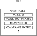
- FIG. 4 shows an example of schematic data structure of the voxel data VD.
- the voxel data VD includes the parameter information for expressing the point clouds in the voxel by a normal distribution.
- the voxel data VD includes the voxel ID, the voxel coordinates, the mean vector, and the covariance matrix, as shown in FIG. 4 .
- the "voxel coordinates" indicate the absolute three-dimensional coordinates of the reference position such as the center position of each voxel.
- each voxel is a cube obtained by dividing the space into lattice shapes. Since the shape and size of the voxel are determined in advance, it is possible to identify the space of each voxel by the voxel coordinates.
- the voxel coordinates may be used as the voxel ID.
- the self-position estimation unit 15 calculates an overall evaluation function value (also referred to as "score value") "E(k)" targeting all the voxels to be matched, which is shown by the following Formula (5).
- the score value E serves as an indicator of the fitness of the matching.
- E n E 1 + E 2 + ⁇ + E M
- the self-position estimation unit 15 calculates the estimation parameter P which maximize the score value E(k) by an arbitrary root finding algorithm such as Newton method.
- the self-position estimation unit 15 calculates the self-position based on the NDT scan matching (also referred to as the "NDT position") "X NDT (k)” by applying the estimated parameter P to the position (also referred to as the "DR position") "X DR (k)” calculated by the dead reckoning at the time k.
- the DR position X DR (k) corresponds to the tentative self-position prior to the calculation of the estimated self-position X ⁇ (k), and is also referred to as the predicted self-position "X"(k)".
- the NDT position X NDT (k) is expressed by the following Formula (6).
- the self-position estimation unit 15 regards the NDT position X NDT (k) as the final estimation result of the self-position at the present processing time k (also referred to as the "estimated self-position") "X ⁇ (k)".
- the obstacle/ship-wave detection unit 16 detects obstacles or ship-waves by using the water-surface height calculated in the processes up to one time before. When there are obstacles near the ship, it is necessary to navigate to avoid collision or contact with the obstacles. Obstacles are, for example, other ships, piles, bridge piers, buoys, nets, garbage, etc. Care should also be taken when navigating the ship in the presence of the ship-waves caused by other ships so that the effects of such waves do not cause significant shaking. Therefore, the obstacle/ship-wave detection unit 16 detects obstacles or ship-waves in the vicinity of the ship using the water-surface height.
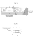
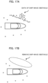
- FIG. 5 is a diagram for explaining the water-surface height viewed from the Lidar 3.
- the ship's waterline position changes according to the number of passengers and the cargo volume. That is, the height to the water surface viewed from the Lidar 3 is changed.
- FIG. 5A when the waterline position of the ship is low, the water-surface position viewed from the Lidar 3 is low.
- FIG. 5B when the waterline position of the ship is high, the water-surface position viewed from the Lidar 3 becomes high. Therefore, as shown in FIG. 5C , by setting the search range having a predetermined width with respect to the water-surface position, it is possible to correctly detect obstacles and ship-waves.
- FIG. 6 is a diagram for explaining the water-surface reflection of the emitted light of the Lidar 3. Some of the emitted light of the Lidar 3 directed downward may be reflected by the water surface and return to the Lidar 3. Now, as shown in FIG. 6A , it is assumed that the Lidars 3 on the ship are emitting the laser light.
- FIG. 6B shows the light received by the Lidars 3 on the ship near the wharf.
- the beams 101 are a portion of the scattered light of the light irradiated directly to the object and then returned to the Lidar 3 and received, without being reflected by the water surface.
- the beams 102 are the light emitted from the lidar 3, reflected by the water surface, and then returned directly back to the Lidar 3 and received.
- the beams 102 are one of the water-surface reflection light (hereinafter, also referred to as "direct water-surface reflection light”).
- the beams 103 are the light emitted from the Lidar 3, whose reflected light by the water surface hit the wharf or the like, a portion of the confused light caused by hitting the wharf is reflected by the water surface again, and then returned back to the Lidar 3 and received.
- the beam 103 are one of the water-surface reflection light (hereinafter, also referred to as "indirect water-surface reflection light”).
- the Lidar 3 cannot recognize that the light is reflected by the water surface.
- the Lidar 3 when receiving the beams 102, the Lidar 3 recognizes as if there is an object at the water surface position. Further, when receiving the beams 103, the Lidar 3 recognizes as if there is an object below the water surface. Therefore, the Lidar 3 that has received the beams 103 will output incorrect point cloud data indicating the position inside the wharf as shown.
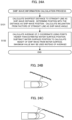
- FIG. 7A and 7B are diagrams illustrating the point cloud data used for estimating the water-surface height (hereinafter, referred to as "water-surface position").
- FIG. 7A is a view of the ship from the rear
- FIG. 7B is a view of the ship from above.
- the beam from the Lidar 3 become substantially perpendicular to the water surface due to the fluctuation of the water surface, and the direct water-surface reflection light like the beams 102 described above is generated.
- the beams from the Lidar 3 are reflected by the shore or the like and the indirect water-surface reflection light like the beams 103 described above is generated.
- the obstacle/ship-wave detection unit 16 acquires a plurality of point cloud data of the direct water-surface reflection light in the vicinity of the ship, and averages their z-coordinate values to estimate the water-surface position. Since the ship is floating on the water, the amount of sinking in the water changes according to the number of passengers and the cargo volume, and the height from the Lidar 3 to the water surface changes. Therefore, by the above method, it is possible to always calculate the distance from the Lidar 3 to the water surface.
- the obstacle/ship-wave detection unit 16 extracts, from the point cloud data outputted by the Lidar 3, the point cloud data measured at the position far from the shore and close to the ship.
- the position far from the shore refers to a position at least a predetermined distance away from the shore.
- the berthing locations including shore and piers
- the shore may be a ground position or structure other than the berthing location.
- the position close to the ship is a position within a predetermined range from the self-position of the ship.
- FIG. 8 is a diagram illustrating a method of detecting an obstacle.
- the obstacle/ship-wave detection unit 16 performs Euclidean clustering processing on the point cloud data at the height near the water-surface position.
- the obstacle/ship-wave detection unit 16 provisionally determines the cluster as an obstacle candidate.
- the obstacle/ship-wave detection unit 16 detects clusters in the same manner at a plurality of time frames, and determines the cluster as some kind of obstacle when the cluster of the same size is detected at each time.
- the water-surface reflection component can also be valuable information from the viewpoint of detection.
- the beams 111 are emitted from the Lidar 3, reflected by the buoy and returned to the Lidar 3.
- the beams 112 are emitted from the Lidar 3, and reflected by the water surface to hit the buoy. A portion of the confused light caused by hitting the buoy is reflected by the water surface again, and is returned to the Lidar 3 and received.
- the number of data directly reflected by the buoy as the beams 111 is small.
- the number of data used for analysis can be increased and utilized for clustering. This improves the performance of the clustering because the number of data subjected to the clustering processing can be increased.
- the obstacle/ship-wave detection unit 16 determines the detected cluster to be an obstacle, it subtracts the water-surface position from the z-coordinate of the highest point of the obstacle to calculate the height Ho of the obstacle coming out of the water surface, as shown in FIG. 8B .
- FIG. 9 is a diagram for explaining a method of detecting the ship-wave.
- the obstacle/ship-wave detection unit 16 performs Hough transform on the point cloud data of the height near the water-surface position, as a point cloud of the two-dimensional plane by ignoring the z-coordinate.
- a "straight-line" is detected by the Hough transform processing, and the obstacle/ship-wave detection unit 16 provisionally determines the straight-line to be a ship-wave candidate.
- the obstacle/ship-wave detection unit 16 similarly performs the straight-line detection in a frame of a plurality of times. When a straight-line having a similar coefficient is detected at each time, the obstacle/ship-wave detection unit 16 determines the straight-line to be the ship-wave.
- the water-surface reflection component when detecting the ship-wave, the water-surface reflection component can also be valuable information from the viewpoint of detection.
- the beams 113 are emitted from the Lidar 3, reflected by the ship-wave and returned to the Lidar 3.
- the beam 114 is emitted from the Lidar 3, and reflected by the water surface to hit the ship-wave. A portion of the confused light caused by hitting the ship-wave is reflected by the water surface again, and returned to the Lidar 3 and received.
- the number of data directly reflected by the ship-wave and return like the beams 113 is small.
- the number of data used for analysis is increased and utilized for the Hough transformation.
- the performance of the Hough transformation is improved.
- the obstacle/ship-wave detection unit 16 After determining the ship-wave using the two-dimensional data as described above, the obstacle/ship-wave detection unit 16 evaluates the z-coordinate of the points which are determined to be a part of the ship-wave once again. Specifically, the obstacle/ship-wave detection unit 16 calculates the average value of the z-coordinates using only the points whose z-coordinate value is higher than the water-surface height, and subtracts the water-surface position from the average value to calculate the height Hw of the ship-wave from the water surface.
- the obstacle/ship-wave detection unit 16 performs the processing in the order of the ship-wave detection ⁇ the obstacle detection ⁇ the water-surface position estimation, thereby to facilitate the subsequent process. Specifically, the obstacle/ship-wave detection unit 16 determines the heights of the ship-wave and the obstacle by using the water-surface position estimated by the water-surface position estimation block 132, and uses them for setting the search range for the point cloud data of the next time.
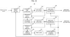
- FIG. 10 is a block diagram showing a functional configuration of the obstacle/ship-wave detection unit 16.
- the obstacle/ship-wave detection unit 16 receives the point cloud data measured by the Lidar 3, and outputs the ship-wave information and the obstacle information.
- the obstacle/ship-wave detection unit 16 includes a search range setting block 121, a straight-line extraction block 122, a ship-wave detection block 123, a ship-wave information calculation block 124, a ship-wave data removal block 125, a Euclidean clustering block 126, an obstacle detection block 127, an obstacle information calculation block 128, an obstacle data removal block 129, an mean/variance calculation block 130, a time filter block 131, and a water-surface position estimation block 132.
- the search range setting block 121 extracts the point cloud data of the direct water-surface reflection light from the inputted point cloud data, and sets the search range of the obstacle and the ship-wave in the height direction.
- the obstacle/ship-wave detection unit 16 detects obstacles and ship-waves by extracting and analyzing the point cloud data belonging to the search range set around the water-surface position as shown in FIG. 5C .
- the search range is increased to avoid it, irrelevant data will enter when the wave is small, and the detection accuracy will decrease.
- the search range setting block 121 calculates the standard deviation of the z-coordinate values of the direct water-surface reflection data obtained in the vicinity of the ship as described above, and sets the search range using the value of the standard deviation. Specifically, the search range setting block 121 estimates the height of the wave (wave height) using the standard deviation of the z-coordinate values of the direct water-surface reflection data, and sets the search range in accordance with the wave height. When the standard deviation of the z-coordinate values of the direct water-surface reflection data is small, it is presumed that the wave height is small as shown in FIG. 11A . In this case, the search range setting block 121 narrows the search range. For example, the search range setting block 121 sets the search range in the vicinity of the average value of the z-coordinate value of the direct water-surface reflection data. Thus, since the mixture of the noise can be reduced, the detection accuracy of the obstacle and ship-wave is improved.
- the search range setting block 121 expands the search range. That is, the search range setting block 121 sets a search range which is wider than the case where the wave height is smaller and which is centered on the average value of the z-coordinate values of the direct water-surface reflection data.
- the search range setting block 121 may set the search range to be a range of ⁇ 3 ⁇ around the average value of the z-coordinate value of the direct water-surface reflection data by using the standard deviation ⁇ of the z-coordinate values of the direct water-surface reflection data.
- the search range setting block 121 outputs the set search range to the straight-line extraction block 122.
- the straight-line extraction block 122 extracts a straight-line from the direct water-surface reflection data measured within the search range around the ship (hereinafter, also referred to as "search data") using Hough transform.
- the straight-line extraction block 122 outputs the extracted straight-line to the ship-wave detection block 123. Since a discretized two-dimensional array is used to detect straight-lines by the Hough transform, the resulting straight-lines are approximate. Therefore, the straight-line extraction block 122 and the ship-wave detection block 123 calculate more accurate straight-lines by the following procedure.
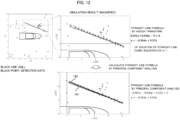
- FIG. 12 shows the result of a simulation for detecting a straight-line in the above procedure.
- the straight-line 141 obtained by the Hough transform is an approximate straight-line, it can be seen that there is a slight deviation from the data.
- the accurate straight-line of the ship-wave can be obtained by extracting data within the linear distance threshold from the straight-line 141 (marked by " ⁇ " in FIG. 12 ) and calculating a straight-line again by the principal component analysis using the extracted data.
- the ship-wave detection block 123 determines the straight-line calculated again as the ship-wave, and outputs the ship-wave data indicating the ship-wave to the ship-wave information calculation block 124 and the ship-wave data removal block 125.
- the ship-wave information calculation block 124 calculates the position, the distance, the angle and the height of the ship-wave based on the formula of the straight-line indicating the ship-wave and the self-position of the ship, and outputs them as the ship-wave information.
- the ship-wave data removal block 125 removes the ship-wave data from the search data measured within the search range around the ship, and outputs it to the Euclidean clustering block 126.
- the Euclidean clustering block 126 performs the Euclidean clustering processing on the inputted search data to detect a cluster of the search data, and outputs the detected cluster to the obstacle detection block 127.
- the distance to all other points is calculated. Then, the points whose obtained distance to other point is shorter than a predetermined value (hereinafter, referred to as "grouping threshold”) are put into the same group. Next, among the groups, a group including the points equal to or more than a predetermined number (hereinafter, referred to as "point-number threshold”) is regarded as a cluster. Since a group including a small number of points may be a noise with high possibility, and is not regarded as a cluster.
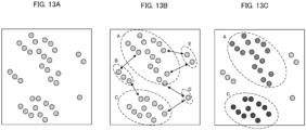
- FIGS. 13A to 13C show an example of Euclidean clustering.
- FIG. 13A shows multiple points subjected to the Euclidean clustering.
- the grouping was performed by calculating the point-to-point distance of each point shown in FIG. 13A and comparing it with the grouping threshold. Since the distance indicated by each arrow in FIG. 13B is greater than the grouping threshold, five groups A to E shown by the dashed lines in FIG. 13B were obtained. Next, the number of points belonging to each group is compared with the point-number threshold (here referred to as "6.") as shown in FIG. 13C , and only the groups A and C including the points of the number larger than the point-number threshold was finally determined as the clusters.
- the point-number threshold here referred to as "6."
- FIGS. 14A and 14B show the simulation results of the Euclidean clustering.
- FIG. 14A shows the simulation result for the case where the ship-wave data remains during the Euclidean clustering.
- the group discrimination is carried out by the grouping threshold in the Euclidean clustering, if the ship-wave data remains, there is a possibility that the obstacle and the ship-wave may be judged as the same cluster.
- the data of the obstacle and the ship-wave wave belong to the same group because the ship-wave and the obstacle are close to each other. Since the number of points of the group is higher than the point-number threshold, they are detected as the same cluster.
- FIG. 14B shows the simulation result when the Euclidean clustering is performed after removing the ship-wave data.
- the ship-wave detection is carried out first, and the Euclidean clustering was carried out after removing the data determined to be the ship-wave data. In this case, the obstacles are correctly detected as the clusters, without being affected by the ship-wave data.
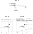
- the Lidar's light beam is outputted radially. Therefore, the farther the data is, the wider the distance between the positions will be. Therefore, as shown in FIG. 15 , the farther the data is, the longer the distance to the adjacent data. Further, even for the object of the same size, the number of the detected points is large if it exists near, and the number of the detected points is small if it exists far. Therefore, in the Euclidean clustering processing, by setting the grouping threshold and the point-number threshold in accordance with the distance value of the data, it is possible to perform the clustering determination with as similar condition as possible, even for a far object from the Lidar.
- FIGS. 16A and 16B show the results of the simulation performed by increasing the grouping threshold as the distance of the data is greater, and decreasing the point-number threshold as the distance to the center of gravity of the group is greater.
- FIG. 16A shows the simulation result in the following case.
- FIG. 16B shows the simulation result in the following case.
- Grouping threshold a ⁇ Data distance
- Point ⁇ number threshold b/ Distance to the center of gravity of the group
- the cluster 2 located far from the ship is detected in addition to the cluster 1 located near the ship in FIG. 16B .
- the cluster 2 although the distance between the data is a value close to 3m, the grouping threshold calculated using the distance from the ship to the data is about 4.5m and the distance is closer than the threshold value. Therefore, the data in the cluster 2 are put into the same group. Also, although the number of data points is 4 points, the point-number threshold calculated using the distance to the center of gravity of the group is about 3.2 and the number of the data points is larger than the threshold. Therefore, those data are determined to be a cluster.
- the grouping threshold calculated using the distance from the ship to the data is a value close to 2.5m and the point-number threshold is about 7.1. Therefore, it can be seen that the cluster 1 does not change significantly compared to the fixed value in FIG. 16A .
- detection failure and erroneous detection of the cluster can be prevented as much as possible, thereby improving the performance of the obstacle detection.
- the obstacle detection block 127 outputs the point cloud data (hereinafter, referred to as "obstacle data") indicating the obstacle detected by the Euclidean clustering to the obstacle information calculation block 128 and the obstacle data removal block 129.
- the obstacle information calculation block 128 calculates the position, the distance, the angle, the size, and the height of the obstacle based on the self-position of the ship, and outputs them as the obstacle information.
- the obstacle data removal block 129 removes the obstacle data from the search data measured within the search range around the ship and outputs the search data to the mean/variance calculation block 130. This is because, when estimating the water-surface position from the direct water-surface reflection data around the ship, the water-surface position cannot be correctly estimated if there are ship-waves or obstacles.
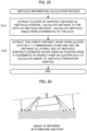
- FIG. 17A shows the direct water-surface reflection data obtained when there are ship-waves or obstacles around the ship.
- the data at the position higher than the water surface, or the indirect water-surface reflection light caused by the obstacle or the ship-wave (e.g., the beams 112 in FIG. 8B , the beam 114 in FIG. 9B , etc.) becomes an error factor in the water-surface position estimation. Therefore, the water-surface position estimation is performed by the ship-wave data removal block 125 and the obstacle data removal block 129 using the search data after removing the ship-waves or the obstacles as shown in FIG. 17B . Specifically, as shown in FIG.
- the ship-wave is detected and removed as shown in the state 2 to create the state 3.
- the obstacle is detected and removed as shown in the state 4 to obtain the direct water-surface reflection data that does not include a ship-wave or an obstacle, as shown in the state 5.
- the mean/variance calculation block 130 calculates the average value and the variance value of the z-coordinate values of the direct water-surface reflection data obtained around the ship, and outputs the values to the time filter block 131.
- the time filter block 131 performs an averaging process or a filtering process of the average value of the z-coordinate values of the inputted direct water-surface reflection data with the past water-surface positions.
- the water-surface position estimation block 132 estimates the water-surface position using the average value of the z-coordinate values after the averaging process or the filtering process and the variance value of the z-coordinate values of the search data.
- the water-surface position estimation block 132 estimates and updates the water-surface position using the average value of the direct water-surface reflection data. On the other hand, when the variance value is equal to or larger than the predetermined value, the water-surface position estimation block 132 does not update the water-surface position and maintains the previous value.
- the "predetermined value” may be a fixed value, a value set based on the average value of the past variance value, e.g., twice the average value of the variance value. Then, the water-surface position estimation block 132 outputs the estimated water-surface position to the search range setting block 121, the ship-wave information calculation block 124 and the obstacle information calculation block 128. Thus, the ship-waves and obstacles are detected, while updating the water-surface position based on the newly obtained direct water-surface reflection data.
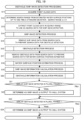
- FIG. 19 is a flowchart of the obstacle/ship-wave detection processing. This processing is realized by the controller shown in FIG. 2 , which executes a program prepared in advance and operates as the elements shown in FIG. 10 .
- the obstacle/ship-wave detection unit 16 acquires the point cloud data measured by the Lidar 3 (step S11).
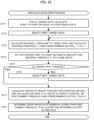
- FIG. 20 is a flowchart of the ship-wave detection process.
- the straight-line extraction block 122 regards each point of the search data obtained from the search range as the two-dimensional data of x- and y-coordinates, by ignoring the z-value (step S101).
- the straight-line extraction block 122 calculates ( ⁇ , ⁇ ) by changing ⁇ in the range of 0 to 180 degrees for all the search points using the following Formula (7) (step S102).
- “ ⁇ " and " ⁇ " are expressed as integers to create a discretized two-dimensional array having ( ⁇ , ⁇ ) as the elements.
- Formula (7) is the formula of the straight-line L represented by using ⁇ and ⁇ , when a perpendicular line is drawn to the straight-line L in FIG. 21 , and the foot of the perpendicular line is expressed as "r”, the distance of the perpendicular line is expressed as " ⁇ ”, and the angle between the perpendicular line and the x-axis is ⁇ .
- the straight-line extraction block 122 examines the number of ( ⁇ , ⁇ ), and extracts a maximum value greater than the predetermined value (step S103). If we extract n ( ⁇ , ⁇ ), we get ( ⁇ 1 , ⁇ 1 ) ⁇ ( ⁇ n , ⁇ n ). Then, the straight-line extraction block 122 substitutes the extracted ( ⁇ 1 , ⁇ 1 ) ⁇ ( ⁇ n , ⁇ n ) into the Expression (7) and generates n straight-lines L 1 ⁇ L n (step S104).
- the ship-wave detection block 123 calculates the distances to the generated n-lines L 1 ⁇ L n for all the search points again, and determines the data whose distance is equal to or smaller than the predetermined distance as the ship-wave data (step S105).
- the ship-wave detection block 123 regards the three-dimensional data including the z-value as the ship-wave data (step S106).
- the ship-wave detection block 123 calculates the formulas of the n straight-lines again, using the extracted ship-wave data, by using the least squares method or the principal component analysis (step S107). Then, the process returns to the main routine of FIG. 19 .
- the ship-wave data removal block 125 removes the ship-wave data from the search data to prepare the search data for obstacle detection (step S15).
- FIG. 22 is a flowchart of the obstacle detection process.
- the Euclidean clustering block 126 calculates, for all the search data, the point-to-point distances to all the other search data (step S111). If the number of the search data is n, then n(n-1) point-to-point distances are calculated.
- the Euclidean clustering block 126 puts the data whose point-to-point distance to the target data is smaller than the grouping threshold T1 into the same group (step S1 14).
- the Euclidean clustering block 126 determines whether or not all of the search data has been targeted (step S1 15). If all the search data has not been targeted (step S115: No), the Euclidean clustering block 126 selects the next target data (step S116) and returns to step S 113.
- the Euclidean clustering block 126 determines, for each group, the group including the data of the number equal to or greater than the point-number threshold T2 as a cluster, and the obstacle detection block 127 determines the cluster as an obstacle (step S118). Then, the process returns to the main routine of FIG. 19 .
- the obstacle data removal block 129 removes the data determined to be the obstacle from the search data to prepare the data for the water-surface position estimation (Step S17).
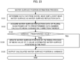
- FIG. 23 is a flowchart of the water-surface position estimation process.
- the mean/variance calculation block 130 determines the data that is far from the shore, close to the ship position, and exists near the water-surface position as the water-surface reflection data (step S121).
- the mean/variance calculation block 130 acquires the water-surface reflection data of the plural scan frames.
- the mean/variance calculation block acquires the predetermined number of data, it calculates the mean and variance values in the z-direction thereof (step S122).
- the mean/variance calculation block 130 determines whether or not the variance value is smaller than a predetermined value (step S123). If the variance value is not smaller than the predetermined value (step S123: No), the process proceeds to step S125. On the other hand, if the variance value is smaller than a predetermined value (step S123: Yes), the time filter block 131 performs the filtering process of the average value of the acquired z values and the estimated water-surface positions in the past, thereby to update the water-surface position (step S124). Next, the water-surface position estimation block 132 outputs the calculated water-surface position and the variance value (step S125). Then, the process returns to the main routine of FIG. 19 .
- FIG. 24A is a flowchart of a ship-wave information calculation process.
- the ship-wave information calculation block 124 calculates the shortest distance to the straight-line detected by the ship-wave detection block 123, and uses the distance as the distance to the ship-wave.
- the ship-wave information calculation block 124 calculates the position with the distance, and uses the position as the position of the ship-wave.
- the ship-wave information calculation block 124 calculates the inclination from the coefficient of the straight-line, and uses the inclination as the angle of the ship-wave (step S131).
- the shortest distance from the ship's self-position to the straight-line is the distance to the foot of the perpendicular line drawn to the straight-line.
- the straight-line detected as the ship-wave is a line segment
- the end point of the data detected as the ship-wave is the shortest distance as shown in FIG. 24C . Therefore, the ship-wave information calculation block 124 checks whether or not the line segment includes the coordinates of the foot of the perpendicular line, and uses the distance to the end point as the shortest distance if the line segment does not include the coordinates of the foot of the perpendicular line.
- the ship-wave information calculation block 124 calculates the average of the z-coordinate values using only the points whose z-value are higher than the estimated water-surface position, and calculates the height of the ship-wave from the water surface using the estimated water-surface position (step S132). Instead of the average value of the z-coordinate values, the maximum value of the z-coordinate values may be used as the height of the ship-wave. Then, the process returns to the main routine of FIG. 19 .
- FIG. 25 is a flowchart illustrating an obstacle information calculation process.
- the obstacle information calculation block 128 extracts the one of the clusters having the shortest distance, among the clusters detected as the obstacles, by using the self-position of the ship as a reference, and determines the position of the obstacle.
- the obstacle information calculation block 128 calculates the distance to the data as the distance to the obstacle.
- the obstacle information calculation block 128 calculates the angle of the obstacle from the coordinates of the data (step S141).
- the obstacle information calculation block 128 extracts two points in the cluster data that are farthest apart in the x-y two-dimensional plane, and determines the distance as the lateral size of the obstacle. In addition, the obstacle information calculation block 128 subtracts the water-surface position from the z-coordinate of the highest point among the cluster data to calculate the height of the obstacle from the water surface (step S142). Then, the process returns to the main routine of FIG. 19 .
- the obstacle/ship-wave detection unit 16 determines whether or not similar ship-waves are detected in a plurality of frames (step S21). When the ship itself or the ship-wave moves, it does not exactly coincide. However, if there is only slight difference in the values calculated in step S19, the obstacle/ship-wave detection unit 16 determines them to be similar ship-waves. If similar ship-waves are not detected (step S21: No), the process proceeds to step S23. On the other hand, if similar ship-waves are detected (step S21: Yes), the ship-wave information calculate block 124 determines the data to be the ship-wave, and outputs the ship-wave information to the hull system (step S22).
- the obstacle/ship-wave detection unit 16 determines whether or not similar obstacles are detected in a plurality of frames (step S23). When the ship itself or the obstacle moves, it does not exactly coincide. However, if there is only slight difference in the values calculated in step S20, the obstacle/ship-wave detection unit 16 determines them to be similar obstacles. If the similar obstacles are not detected (step S23: No), the process ends. On the other hand, if similar obstacles are detected (step S23: Yes), the obstacle information calculation block 128 determines the data to be the obstacle and outputs the obstacle information to the hull system (step S24). Then, the process ends.
- the water-surface position estimation block 132 may process the water-surface reflection data on the starboard side and the water-surface reflection data on the port side separately, and determine the water-surface position on the starboard side and the water-surface position on the port side separately.
- the water-surface position estimation block 132 can estimate the water-surface position without separating the starboard and port sides by applying a coordinate transformation for rotating the roll angle to the water-surface reflection data so that the difference between the average value of the starboard side of the water-surface reflection data and the average value of the port side of the water-surface reflection data becomes small.
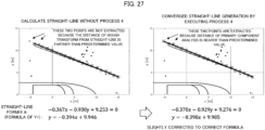
- the straight-line extraction block 122 extracts a straight-line of the ship-wave by the following Processes 1 to 3.
- Process 4 may be added to repeatedly execute Processes 2 and 3 according to the determination result of of Process 4. (Process 4) If the extracted data changes and the formula of the straight-line changes, the process returns to Process 2. When the formula of the straight-line does not change, it is determined to be the straight-line of the ship-wave.
- the graph on the left side of FIG. 27 shows an example in which the straight-line is obtained without carrying out the above-described Process 4.
- the graph on the right side shows an example in which the straight-line generation is converged by carrying out up to Process 4.
Landscapes
- Engineering & Computer Science (AREA)
- Physics & Mathematics (AREA)
- Radar, Positioning & Navigation (AREA)
- Remote Sensing (AREA)
- Computer Networks & Wireless Communication (AREA)
- General Physics & Mathematics (AREA)
- Electromagnetism (AREA)
- Optical Radar Systems And Details Thereof (AREA)
Applications Claiming Priority (1)
| Application Number | Priority Date | Filing Date | Title |
|---|---|---|---|
| PCT/JP2021/010365 WO2022195670A1 (ja) | 2021-03-15 | 2021-03-15 | 情報処理装置、制御方法、プログラム及び記憶媒体 |
Publications (2)
| Publication Number | Publication Date |
|---|---|
| EP4310550A1 true EP4310550A1 (de) | 2024-01-24 |
| EP4310550A4 EP4310550A4 (de) | 2025-01-08 |
Family
ID=83320012
Family Applications (1)
| Application Number | Title | Priority Date | Filing Date |
|---|---|---|---|
| EP21931426.7A Pending EP4310550A4 (de) | 2021-03-15 | 2021-03-15 | Informationsverarbeitungsvorrichtung, steuerungsverfahren, programm und speichermedium |
Country Status (4)
| Country | Link |
|---|---|
| US (1) | US20240175984A1 (de) |
| EP (1) | EP4310550A4 (de) |
| JP (2) | JP7539552B2 (de) |
| WO (1) | WO2022195670A1 (de) |
Families Citing this family (5)
| Publication number | Priority date | Publication date | Assignee | Title |
|---|---|---|---|---|
| EP3758771B1 (de) | 2018-02-28 | 2025-10-01 | NxStage Medical, Inc. | Methoden zur flüssigkeitszubereitung |
| EP4186848B1 (de) * | 2021-11-30 | 2024-05-15 | B&R Industrial Automation GmbH | Trajektorienplanung mit flexibler umplanungsfunktionalität - hindernis |
| WO2024189755A1 (ja) * | 2023-03-14 | 2024-09-19 | 三菱電機株式会社 | 推定装置、推定システムおよび推定方法 |
| CN119429016B (zh) * | 2024-11-29 | 2025-11-14 | 沪东中华造船(集团)有限公司 | 一种用于大线型分段排舷外管的安装方法 |
| CN119763055B (zh) * | 2024-12-19 | 2025-07-18 | 芜湖太航信息技术有限公司 | 一种基于图像识别的船舶承载预判系统 |
Family Cites Families (13)
| Publication number | Priority date | Publication date | Assignee | Title |
|---|---|---|---|---|
| JP4394029B2 (ja) | 2005-04-06 | 2010-01-06 | 三菱電機株式会社 | 目標検出装置 |
| JP4919047B2 (ja) | 2007-05-09 | 2012-04-18 | 株式会社Ihi | 三次元センサのデータ補正装置及び方法 |
| NO332432B1 (no) | 2008-08-12 | 2012-09-17 | Kongsberg Seatex As | System for deteksjon og avbildning av objekter i banen for marine fartoy |
| JP5741833B2 (ja) | 2011-05-10 | 2015-07-01 | 株式会社Ihi | レーザレーダ装置及びレーザレーダ法 |
| WO2013076829A1 (ja) | 2011-11-22 | 2013-05-30 | 株式会社日立製作所 | 自律移動システム |
| JP6258310B2 (ja) | 2013-05-31 | 2018-01-10 | 古野電気株式会社 | 引き波検出装置、レーダ装置、引き波検出方法、及び引き波検出プログラム |
| JP2016206152A (ja) | 2015-04-28 | 2016-12-08 | 古野電気株式会社 | 波浪レーダ装置 |
| JP6785421B2 (ja) | 2016-01-27 | 2020-11-18 | 国立大学法人千葉大学 | 波浪計測装置及び物標探知装置 |
| WO2017204076A1 (ja) | 2016-05-26 | 2017-11-30 | 古野電気株式会社 | 信号処理装置及びレーダ装置 |
| EP3633320A4 (de) | 2017-05-31 | 2021-03-17 | Pioneer Corporation | Ausgabevorrichtung, steuerungsverfahren, programm und speichermedium |
| JP7083081B2 (ja) | 2018-10-10 | 2022-06-10 | ヤンマーパワーテクノロジー株式会社 | 自動着岸装置 |
| CN109917414B (zh) | 2019-03-20 | 2021-03-16 | 北京视酷伟业科技股份有限公司 | 一种基于激光技术的船舶干舷测定方法及系统 |
| CN111239766B (zh) * | 2019-12-27 | 2021-12-07 | 北京航天控制仪器研究所 | 基于激光雷达的水面多目标快速识别跟踪方法 |
-
2021
- 2021-03-15 EP EP21931426.7A patent/EP4310550A4/de active Pending
- 2021-03-15 WO PCT/JP2021/010365 patent/WO2022195670A1/ja not_active Ceased
- 2021-03-15 JP JP2023506395A patent/JP7539552B2/ja active Active
- 2021-03-15 US US18/282,120 patent/US20240175984A1/en active Pending
-
2024
- 2024-08-13 JP JP2024134980A patent/JP2024155952A/ja active Pending
Also Published As
| Publication number | Publication date |
|---|---|
| JP7539552B2 (ja) | 2024-08-23 |
| US20240175984A1 (en) | 2024-05-30 |
| JPWO2022195670A1 (de) | 2022-09-22 |
| JP2024155952A (ja) | 2024-10-31 |
| EP4310550A4 (de) | 2025-01-08 |
| WO2022195670A1 (ja) | 2022-09-22 |
Similar Documents
| Publication | Publication Date | Title |
|---|---|---|
| EP4310550A1 (de) | Informationsverarbeitungsvorrichtung, steuerungsverfahren, programm und speichermedium | |
| JPWO2018221453A1 (ja) | 出力装置、制御方法、プログラム及び記憶媒体 | |
| JP2024177452A (ja) | 情報処理装置、制御方法、プログラム及び記憶媒体 | |
| JP2025039580A (ja) | 情報処理装置、制御方法、プログラム及び記憶媒体 | |
| JP7748811B2 (ja) | 情報処理装置、制御方法、プログラム及び記憶媒体 | |
| JP2025174996A (ja) | 情報処理装置、判定方法、プログラム及び記憶媒体 | |
| JP2025036645A (ja) | 情報処理装置、制御方法、プログラム及び記憶媒体 | |
| JP7549129B2 (ja) | 地図データ構造、記憶装置、情報処理装置、制御方法、プログラム及び記憶媒体 | |
| EP4494999A1 (de) | Informationsverarbeitungsvorrichtung, steuerungsverfahren, programm und speichermedium | |
| KR102469164B1 (ko) | 무인 수상선의 지구물리적 내비게이션 장치 및 방법 | |
| JP7724302B2 (ja) | 情報処理装置、制御方法、プログラム及び記憶媒体 | |
| JP7750661B2 (ja) | 情報処理装置、制御方法、プログラム及び記憶媒体 | |
| JP2025137507A (ja) | 情報処理装置、制御方法、プログラム及び記憶媒体 | |
| Huang et al. | Seafloor obstacle detection by sidescan sonar scanlines for submarine cable construction | |
| JP2025182006A (ja) | 情報処理装置、制御方法、プログラム及び記憶媒体 | |
| JP7658008B2 (ja) | 情報処理装置、制御方法、プログラム及び記憶媒体 | |
| US20250199176A1 (en) | Information processing device, control method, program and storage medium | |
| JP7714429B2 (ja) | 情報処理装置、判定方法、プログラム及び記憶媒体 | |
| US20250189668A1 (en) | Information processing device, control method, program and storage medium | |
| US20250314493A1 (en) | Information processing device, determination method, program, and storage medium | |
| CN119053514A (zh) | 信息处理装置、控制方法、程序及存储介质 | |
| Menozzi et al. | On the development of a framework for underwater localization using all-source data | |
| Beckman | Localization of a Submerged Tow Vehicle (Lost) |
Legal Events
| Date | Code | Title | Description |
|---|---|---|---|
| STAA | Information on the status of an ep patent application or granted ep patent |
Free format text: STATUS: THE INTERNATIONAL PUBLICATION HAS BEEN MADE |
|
| PUAI | Public reference made under article 153(3) epc to a published international application that has entered the european phase |
Free format text: ORIGINAL CODE: 0009012 |
|
| STAA | Information on the status of an ep patent application or granted ep patent |
Free format text: STATUS: REQUEST FOR EXAMINATION WAS MADE |
|
| 17P | Request for examination filed |
Effective date: 20230922 |
|
| AK | Designated contracting states |
Kind code of ref document: A1 Designated state(s): AL AT BE BG CH CY CZ DE DK EE ES FI FR GB GR HR HU IE IS IT LI LT LU LV MC MK MT NL NO PL PT RO RS SE SI SK SM TR |
|
| DAV | Request for validation of the european patent (deleted) | ||
| DAX | Request for extension of the european patent (deleted) | ||
| A4 | Supplementary search report drawn up and despatched |
Effective date: 20241206 |
|
| RIC1 | Information provided on ipc code assigned before grant |
Ipc: G01S 7/497 20060101ALI20241202BHEP Ipc: G01S 17/93 20200101ALI20241202BHEP Ipc: G01S 17/86 20200101ALI20241202BHEP Ipc: G01S 17/08 20060101ALI20241202BHEP Ipc: G01S 17/89 20200101AFI20241202BHEP |